EP4008659B1 - Benutzereingabevorrichtungen - Google Patents
Benutzereingabevorrichtungen Download PDFInfo
- Publication number
- EP4008659B1 EP4008659B1 EP20383051.8A EP20383051A EP4008659B1 EP 4008659 B1 EP4008659 B1 EP 4008659B1 EP 20383051 A EP20383051 A EP 20383051A EP 4008659 B1 EP4008659 B1 EP 4008659B1
- Authority
- EP
- European Patent Office
- Prior art keywords
- input
- regions
- input device
- user input
- user
- Prior art date
- Legal status (The legal status is an assumption and is not a legal conclusion. Google has not performed a legal analysis and makes no representation as to the accuracy of the status listed.)
- Active
Links
Images





Classifications
-
- B—PERFORMING OPERATIONS; TRANSPORTING
- B66—HOISTING; LIFTING; HAULING
- B66B—ELEVATORS; ESCALATORS OR MOVING WALKWAYS
- B66B1/00—Control systems of elevators in general
- B66B1/34—Details, e.g. call counting devices, data transmission from car to control system, devices giving information to the control system
- B66B1/46—Adaptations of switches or switchgear
- B66B1/461—Adaptations of switches or switchgear characterised by their shape or profile
-
- B—PERFORMING OPERATIONS; TRANSPORTING
- B66—HOISTING; LIFTING; HAULING
- B66B—ELEVATORS; ESCALATORS OR MOVING WALKWAYS
- B66B1/00—Control systems of elevators in general
- B66B1/34—Details, e.g. call counting devices, data transmission from car to control system, devices giving information to the control system
- B66B1/46—Adaptations of switches or switchgear
- B66B1/468—Call registering systems
-
- B—PERFORMING OPERATIONS; TRANSPORTING
- B66—HOISTING; LIFTING; HAULING
- B66B—ELEVATORS; ESCALATORS OR MOVING WALKWAYS
- B66B1/00—Control systems of elevators in general
- B66B1/34—Details, e.g. call counting devices, data transmission from car to control system, devices giving information to the control system
- B66B1/46—Adaptations of switches or switchgear
- B66B1/52—Floor selectors
-
- B—PERFORMING OPERATIONS; TRANSPORTING
- B66—HOISTING; LIFTING; HAULING
- B66B—ELEVATORS; ESCALATORS OR MOVING WALKWAYS
- B66B13/00—Doors, gates, or other apparatus controlling access to, or exit from, cages or lift well landings
- B66B13/02—Door or gate operation
- B66B13/14—Control systems or devices
- B66B13/143—Control systems or devices electrical
-
- B—PERFORMING OPERATIONS; TRANSPORTING
- B66—HOISTING; LIFTING; HAULING
- B66B—ELEVATORS; ESCALATORS OR MOVING WALKWAYS
- B66B5/00—Applications of checking, fault-correcting, or safety devices in elevators
- B66B5/02—Applications of checking, fault-correcting, or safety devices in elevators responsive to abnormal operating conditions
-
- G—PHYSICS
- G01—MEASURING; TESTING
- G01S—RADIO DIRECTION-FINDING; RADIO NAVIGATION; DETERMINING DISTANCE OR VELOCITY BY USE OF RADIO WAVES; LOCATING OR PRESENCE-DETECTING BY USE OF THE REFLECTION OR RERADIATION OF RADIO WAVES; ANALOGOUS ARRANGEMENTS USING OTHER WAVES
- G01S17/00—Systems using the reflection or reradiation of electromagnetic waves other than radio waves, e.g. lidar systems
- G01S17/02—Systems using the reflection of electromagnetic waves other than radio waves
- G01S17/06—Systems determining position data of a target
- G01S17/08—Systems determining position data of a target for measuring distance only
-
- G—PHYSICS
- G06—COMPUTING OR CALCULATING; COUNTING
- G06F—ELECTRIC DIGITAL DATA PROCESSING
- G06F3/00—Input arrangements for transferring data to be processed into a form capable of being handled by the computer; Output arrangements for transferring data from processing unit to output unit, e.g. interface arrangements
- G06F3/01—Input arrangements or combined input and output arrangements for interaction between user and computer
- G06F3/03—Arrangements for converting the position or the displacement of a member into a coded form
- G06F3/041—Digitisers, e.g. for touch screens or touch pads, characterised by the transducing means
- G06F3/042—Digitisers, e.g. for touch screens or touch pads, characterised by the transducing means by opto-electronic means
- G06F3/0421—Digitisers, e.g. for touch screens or touch pads, characterised by the transducing means by opto-electronic means by interrupting or reflecting a light beam, e.g. optical touch-screen
-
- B—PERFORMING OPERATIONS; TRANSPORTING
- B66—HOISTING; LIFTING; HAULING
- B66B—ELEVATORS; ESCALATORS OR MOVING WALKWAYS
- B66B2201/00—Aspects of control systems of elevators
- B66B2201/10—Details with respect to the type of call input
- B66B2201/103—Destination call input before entering the elevator car
-
- B—PERFORMING OPERATIONS; TRANSPORTING
- B66—HOISTING; LIFTING; HAULING
- B66B—ELEVATORS; ESCALATORS OR MOVING WALKWAYS
- B66B2201/00—Aspects of control systems of elevators
- B66B2201/40—Details of the change of control mode
- B66B2201/46—Switches or switchgear
- B66B2201/4607—Call registering systems
- B66B2201/4615—Wherein the destination is registered before boarding
-
- B—PERFORMING OPERATIONS; TRANSPORTING
- B66—HOISTING; LIFTING; HAULING
- B66B—ELEVATORS; ESCALATORS OR MOVING WALKWAYS
- B66B2201/00—Aspects of control systems of elevators
- B66B2201/40—Details of the change of control mode
- B66B2201/46—Switches or switchgear
- B66B2201/4607—Call registering systems
- B66B2201/4623—Wherein the destination is registered after boarding
-
- B—PERFORMING OPERATIONS; TRANSPORTING
- B66—HOISTING; LIFTING; HAULING
- B66B—ELEVATORS; ESCALATORS OR MOVING WALKWAYS
- B66B2201/00—Aspects of control systems of elevators
- B66B2201/40—Details of the change of control mode
- B66B2201/46—Switches or switchgear
- B66B2201/4607—Call registering systems
- B66B2201/4638—Wherein the call is registered without making physical contact with the elevator system
Definitions
- This disclosure relates to user input devices for providing an input to an elevator controller of an elevator system.
- Elevator systems typically comprise car operation panels which allow a user to input their destination floor as well as landing panels which allow a user to call an elevator car to their landing. Some landing panels also allow a user to indicate their direction of travel or their destination floor.
- Such car operation panels or landing panels typically comprise a plurality of buttons which a user has to press in order to make their selection. The buttons require physical contact by the user which introduces the possibility of microbes, e.g. bacteria, archaea, protozoa, algae, fungi, viruses etc., being deposited onto the buttons by a user, or being transferred from the buttons onto a user. Certain microbes may cause a user to become ill.
- buttons may be operated by a number of different users of an elevator system, there is a risk that any microbes present on the buttons may be transferred to other users, thus potentially spreading the microbes between the users of the elevator system.
- a large number of users may use a single car operation panel or hall panel and thus the potential for spread of microbes through contact with the car operation panel or landing panel may be significant.
- US 2015/090536 A1 discloses a touch-free control device for an elevator which contains a control panel and at least one distance sensor.
- US 2015/232300 A1 discloses an elevator activation system which comprises an optical sensor or time-of-flight camera positioned near buttons of the elevator and projects an optical curtain over buttons of the elevator.
- JP 2006 021906 A discloses an elevator control panel comprising button devices with infrared devices provided thereon.
- a user input device is provided according to claim 1.
- a user may place an object in any one of the plurality of input regions so as to provide an input command by the user input device.
- the presence of the object in any one of the plurality of input regions is detected by the single touchless sensor and thus the user does not have to come into physical contact with the user input device.
- the user input device of the present disclosure may reduce the spread of microbes.
- the use of a single touchless sensor which is arranged to detect the presence of an object in any of the plurality of input regions, as opposed to a plurality of touchless sensors each arranged to detect the presence of an object in a respective input region, may minimise the number of components required to be capable of determining a user's input command. This may reduce the cost to manufacture the user input device and may also simplify its manufacture and assembly.
- the user may place any suitable object into the plurality of input regions.
- the object which may be placed in the input regions may depend on the size of the input regions.
- the user may, for example, insert a finger into one of the input regions in order to issue an input command.
- the user may insert another object, e.g. a key, into an input region.
- the use of a key may further minimise the chance of depositing microbes on the user input device and minimise the chance of picking up microbes from the user input device.
- the presence of a finger or key may be detected in a touchless manner using the single touchless sensor.
- any other suitable object may be placed into the input regions in order to select an input command.
- the use of a distance sensor may provide a single touchless sensor which is simple to implement on the user input device.
- the distance sensor may determine, i.e. measure, the distance at which an object is present and with knowledge of the distance at which each region is located, it may be possible to determine the input region in which the object is present, and hence determine the intended input command.
- the distance sensor may determine, i.e. measure, the distance at which an object is detected and the controller may then determine the input region in which the object is present. This determination performed by the controller may be based on the known distances of each input region from the distance sensor and the distance measured by the distance sensor.
- the user input device may comprise three input regions each of which corresponds to a destination floor input command.
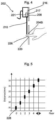
- the first input region, located at 3 cm from the distance sensor may correspond to a third floor input command
- a second input region, located at 5 cm from the distance sensor may correspond to a second floor input command
- a third input region, located at 7 cm from the distance sensor may correspond to a first floor input command.
- the distance sensor When a user places an object, for example, in the second input region, the distance sensor will determine that the object is at 5 cm from the distance sensor. The controller may then take the distance of 5 cm and compare it to the known distances, and determine that a distance of 5 cm corresponds to a second input region which is a second floor input command. This input command may then be used to control an elevator system in an appropriate manner. For example, the input command may be output to a suitable elevator controller. Of course, any number of input regions and associated input commands may be present.
- the known distances of each of the plurality of regions may be stored in the controller, e.g. in a memory thereof, in the form of a look up table, i.e. a table correlating a number of distances with associated input commands.
- the controller may be integrally provided with the distance sensor such that the distance sensor is capable of determining the distance of an object and also capable of determining the input region in which an object is present, and hence the associated input command.
- the distance sensor may then output a determined input command to an elevator controller which then controls the elevator system, e.g. the elevator car, based on the input command.
- the controller may be separate to the distance sensor.
- the controller may be an elevator controller capable of controlling the elevator system.
- the distance sensor may output the distance measured to the controller which may then determine the input region which corresponds to the measured distance.
- the elevator controller may then control the elevator system in an appropriate manner. In either case, the controller may include the known distances to each input region.
- Each input region may be larger than a typical object which may be placed therein.
- the distance determined for an object may have a range of distances for any given input region.
- the known distance for each input region comprises a range of distances. It will therefore be possible to determine the input region in which the object is present, irrespective of its relative position in the input region.
- having the input regions as large as possible may be advantageous in certain instances. For example, where the input regions are at least partially defined by apertures, having the apertures as large as possible, and thus making the input regions as large as possible, may reduce the likelihood of the object coming into contact with the user input device. This may minimise the chance of coming into contact with the user input device and thus reduce the spread of any microbes thereon.
- a range of distances may be stored for each input region.
- a first input region may correspond to distances of 2.5 cm - 3.5 cm from the distance sensor
- a second input region may correspond to distances of 4.5 cm - 5.5 cm from the distance sensor, etc. Accordingly, an object detected at 2.8 cm or 3.2 cm, for example, will be determined to be in the first input region and a corresponding input command will be determined.
- the distance sensor may comprise any suitable arrangement for determining the distance between an object and the distance sensor.
- the distance sensor comprises an emitter configured to emit a beam through the plurality of input regions and a receiver configured to receive the beam reflected by an object placed in one of the plurality of input regions.
- the distance sensor may therefore be a beam-type distance sensor which measures distance based on the emission and subsequent detection of a beam.
- the beam may comprise any electromagnetic beam that is suitable for distance measurement.
- the beam is a light beam, e.g. a laser beam.
- the beam is an infrared beam. Beam-type sensors are typically directional, and thus erroneous measurements from other parts of the user input device may be avoided.
- the beam emitted by the emitter passes through each of the input regions.
- the object may obstruct the beam and a portion of the beam may be reflected back towards the receiver and detected thereon.
- the distance sensor may determine the distance to the object based on a known speed of the beam and the difference in time from emission to detection of the beam.
- a beam-type distance sensor as discussed above, may provide a convenient means for providing touchless detection.
- the beam When there is no object obstructing the beam, the beam may pass through all of the input regions and be directed in a manner such that beam is not reflected back towards the receiver. In this case, the receiver will not detect any reflected beam and thus no distance measurement will be possible.
- the controller may assume that no object is present in any of the input regions and thus conclude that no input command is being entered.
- a portion of the beam may still be reflected back towards the receiver. This may, for example, be due to reflection of the beam from an internal surface within the user input device.
- the controller may be configured to dismiss a measurement corresponding to a reflection from an internal surface within the user input device.
- the beam may pass through all of the input regions and be reflected from an internal surface which is 20 cm back from the distance sensor.
- the controller may be programmed to be aware that a distance measurement of 20 cm does not indicate an input command.
- the input regions may be arranged in any suitable manner such that the single touchless sensor is capable of detecting the presence of an object in any of the plurality of input regions.
- the plurality of input regions are arranged in a straight line.
- the plurality of input regions may be arranged in a vertical straight line. Arranging the plurality of input regions in a straight line may facilitate simple detection with certain types of touchless sensor.
- arranging the plurality of input regions in a straight line may be particularly suitable in examples wherein the single touchless sensor comprises a distance sensor which emits a beam, as the beam may travel in a straight line through each of the plurality of input regions without requiring redirection. This may simplify the design of the user input device.
- the number and/or type of input regions may mean that the input regions cannot be arranged in a single line and thus the beam may not pass through all of the input regions without redirection.
- the plurality of input regions comprises a first subset of input regions and a second subset of input regions, wherein the user input device further comprises a beam director arranged to direct the beam through at least the second subset of input regions.
- the use of a beam director to direct the beam through the second set of input regions may advantageously mean that a single touchless sensor can be used to detect the presence of an object in input regions which are not aligned. This may mean that the user input device may be capable of comprising an increased number of input regions.
- the user input device may further comprise a wall extending behind each aperture which defines the corresponding input region, and wherein the touchless sensor is arranged in the wall.
- the wall may encompass the aperture.
- the wall may be cylindrical in shape and have corresponding dimensions to the aperture.
- the wall may also close a base, i.e. an end, of the input region.
- the wall may have a cylindrical shape with one closed end, i.e. the base, and one open end, defined by the aperture. Closing the base of the input region may limit the extent to which the user can insert an object through the aperture, and thus prevent the user from interfering with components of the user input device.
- the first touchless sensor 316A and the second touchless sensor 316B may be distance sensors and operate in an identical manner to the touchless sensor 216 described above. Accordingly, the user input device 302 may be capable of detecting a user placing an object into the first plurality of input regions 304A-304F as well as detecting a user placing an object into the further plurality of input regions 304G-304L. Whilst not illustrated, each of the touchless sensors 316A, 316B may be connected to an independent or a common controller. The controller may function in a similar manner to the controller 219 described above with reference to Figure 3 .
- Figure 14 shows a side view of focussing on the first input region 602A of the device shown in Figures 12 and 13 .
- the touchless sensor 616A is arranged in a base 623 of the wall 622.
- the base 623 of the wall 622 may be omitted and the touchless sensor 616A may be held in the same position, but by another support structure provided within the user input device 602.
- the wall 622 defines an input region 604A which may be considered to correspond to a recess in the faceplate 608.
- FIG. 14 when a user places an object, e.g. their finger 626, into the input region 604A, its presence may be detected by the touchless sensor 616A.
- the input command corresponding to that input region 604A may then be issued to another controller from the user input device 602, e.g. to an elevator controller, which may then control the elevator system in an appropriate manner.
- Figure 15 illustrates how another object, e.g. a metal object 627 which may for example be a user's key, may be inserted into the input region 604A in order to issue an input command.
- the touchless sensor 616A may specifically be configured to detect the presence of a metal object 627, rather than an object formed from another material.
- any of the user input devices described above may be employed in the elevator system 101 shown in Figure 1 .
- the user input devices may be arranged in the elevator car 103 as car operation panels, or arranged on one or more of the landings 125 as landing panels.
- the input regions in each of the exemplary user input devices described above may be configured to input any suitable input command.
- examples of the present disclosure provide an improved user input device for providing an input to an elevator controller. While specific examples of the disclosure have been described in detail, it will be appreciated by those skilled in the art that the examples described in detail are not limiting on the scope of the claims.
Landscapes
- Engineering & Computer Science (AREA)
- Automation & Control Theory (AREA)
- Computer Networks & Wireless Communication (AREA)
- Physics & Mathematics (AREA)
- General Engineering & Computer Science (AREA)
- General Physics & Mathematics (AREA)
- Theoretical Computer Science (AREA)
- Electromagnetism (AREA)
- Human Computer Interaction (AREA)
- Radar, Positioning & Navigation (AREA)
- Remote Sensing (AREA)
- Elevator Control (AREA)
Claims (12)
- Benutzereingabevorrichtung (202, 302, 402) zum Bereitstellen einer Eingabe an einer Aufzugssteuerung (115), umfassend:eine Vielzahl von Eingabebereichen (204A-204F, 304A-304F, 404A-404L), die jeweils einem anderen Eingabebefehl entspricht; undeinen einzelnen berührungslosen Sensor (216, 316A, 416), der dazu angeordnet ist, das Vorhandensein eines Objekts in einem beliebigen der Vielzahl von Eingabebereichen (204A-204F, 304A-304F, 404A-404L) zu erfassen;dadurch gekennzeichnet, dassder einzelne berührungslose Sensor (216, 316A, 416) hinter einer Frontplatte (208, 308) angeordnet ist und dass sich die Vielzahl von Eingabebereichen (204A-204F, 304A-304F, 404A-404L) hinter der Frontplatte (208, 308) befindet und mindestens teilweise durch eine Vielzahl von Öffnungen (220) innerhalb der Frontplatte (208, 308) definiert ist.
- Benutzereingabevorrichtung (202, 302, 402) nach Anspruch 1, wobei der einzelne berührungslose Sensor einen Abstandssensor (216, 316A, 416) umfasst, der dazu konfiguriert ist, den Abstand zu bestimmen, in dem ein Objekt erfasst wird, und wobei jeder der Vielzahl von Eingabebereichen (204A-204F, 304A-304F, 404A-404L) um einen bekannten Abstand von dem Abstandssensor (216, 316A, 416) beabstandet ist.
- Aufzugssteuerungssystem, umfassend die Benutzereingabevorrichtung (202, 302, 402) nach Anspruch 2 und eine Steuerung (219), wobei die Steuerung (219) dazu konfiguriert ist, basierend auf dem bekannten Abstand jedes der Eingabebereiche (204A-204F, 304A-304F, 404A-404LF) zu dem Abstandssensor (216, 316A, 416) und dem von dem Abstandssensor (216, 316A, 416) bestimmten Abstand den Eingabebereich (204A-204F, 304A-304F, 404A-404L) zu bestimmen, in dem ein Objekt vorhanden ist.
- Benutzereingabevorrichtung (202, 302, 402) oder Aufzugssteuerungssystem nach Anspruch 2 oder 3, wobei der bekannte Abstand jedes Eingabebereichs (204A-204F, 304A-304F, 404A-404L) einen Bereich von Abständen (228) umfasst.
- Benutzereingabevorrichtung (202, 302, 402) oder Aufzugssteuerungssystem nach einem der Ansprüche 2, 3 oder 4, wobei der Abstandssensor (216, 316A, 416) einen Emitter (217), der dazu konfiguriert ist, einen Strahl (210, 310A, 410) durch die Vielzahl von Eingabebereichen (204A-204F, 304A-304F, 404A-404L) zu emittieren, und einen Empfänger (221) umfasst, der dazu konfiguriert ist, den Strahl (210, 310A, 410) zu empfangen, der von einem Objekt (226) reflektiert wird, das in einem der Vielzahl von Eingabebereichen (204A-204F, 304A-304F, 404A-404L) platziert ist.
- Benutzereingabevorrichtung (202, 302, 402) oder Aufzugssteuerungssystem nach einem der vorhergehenden Ansprüche, wobei die Vielzahl von Eingabebereichen (204A-204F, 304A-304F, 404A-404L) in einer geraden Linie angeordnet ist.
- Benutzereingabevorrichtung (402) oder Aufzugssteuersystem nach Anspruch 5, wobei die Vielzahl von Eingabebereichen (404A-404L) eine erste Teilmenge von Eingabebereichen (404A-404F) und eine zweite Teilmenge von Eingabebereichen (404G-404L) umfasst, wobei die Benutzereingabevorrichtung (402) ferner einen Strahlrichter (430) umfasst, der dazu angeordnet ist, den Strahl (410) durch mindestens die zweite Teilmenge von Eingabebereichen (404G-404L) zu richten.
- Benutzereingabevorrichtung (202, 302, 402) nach Anspruch 1 oder Aufzugssteuerungssystem nach Anspruch 3, wobei jede der Öffnungen (220) mindestens eine Wand (222A; 222B) umfasst, die sich hinter der Frontplatte (208) erstreckt und die jeden der Vielzahl von Eingabebereichen (204A-204F, 304A-304F, 404A-404L) teilweise definiert.
- Benutzereingabevorrichtung (202, 302, 402) oder Aufzugssteuerungssystem nach Anspruch 8, wobei die mindestens eine Wand (222A; 222B) mindestens einen mindestens teilweise transparenten Abschnitt (224A; 224B) umfasst, der dazu angeordnet ist, einem Strahl (210, 310A, 410) ein Passieren durch jeden der Vielzahl von Bereichen (204A-204F, 304A-304F, 404A-404L) zu ermöglichen.
- Benutzereingabevorrichtung (302) oder Aufzugssteuerungssystem nach einem der vorhergehenden Ansprüche, wobei die Benutzereingabevorrichtung (302) eine weitere Vielzahl von Eingabebereichen (304G-304L), die jeweils weiteren Eingabebefehlen entspricht, und einen weiteren einzelnen berührungslosen Sensor (316B) umfasst, der dazu angeordnet ist, das Vorhandensein eines Objekts in einem der weiteren Vielzahl von Eingabebereichen (304G-304L) zu erfassen.
- Benutzereingabevorrichtung (202, 302, 402) oder Aufzugssteuerungssystem nach einem der vorhergehenden Ansprüche, wobei die Benutzereingabevorrichtung (202, 302, 402) ein Kabinenbedienfeld zum Einbau in eine Aufzugskabine (103) oder ein Haltbedienfeld zum Einbau in ein Aufzugshalt (125) ist.
- Benutzereingabevorrichtung (202, 302, 402) oder Aufzugssteuersystem nach einem der vorhergehenden Ansprüche, wobei die Vielzahl von Eingabebereichen (204A-204F, 304A-304F, 404A-404L) Bereiche zum Eingeben von mindestens einem der Folgenden umfasst: einen Zieletagenbefehl, einen Türöffnungsbefehl, einen Türschließbefehl, einen Notbetriebsbefehl, einen Alarmbefehl, einen persönlichen Identifikationscode, einen Aufwärtsfahrtbefehl und einen Abwärtsfahrtbefehl.
Priority Applications (3)
| Application Number | Priority Date | Filing Date | Title |
|---|---|---|---|
| EP20383051.8A EP4008659B1 (de) | 2020-12-03 | 2020-12-03 | Benutzereingabevorrichtungen |
| US17/396,169 US20220177267A1 (en) | 2020-12-03 | 2021-08-06 | User input devices |
| CN202110948028.8A CN114604702A (zh) | 2020-12-03 | 2021-08-18 | 用户输入装置 |
Applications Claiming Priority (1)
| Application Number | Priority Date | Filing Date | Title |
|---|---|---|---|
| EP20383051.8A EP4008659B1 (de) | 2020-12-03 | 2020-12-03 | Benutzereingabevorrichtungen |
Publications (2)
| Publication Number | Publication Date |
|---|---|
| EP4008659A1 EP4008659A1 (de) | 2022-06-08 |
| EP4008659B1 true EP4008659B1 (de) | 2025-07-02 |
Family
ID=73834411
Family Applications (1)
| Application Number | Title | Priority Date | Filing Date |
|---|---|---|---|
| EP20383051.8A Active EP4008659B1 (de) | 2020-12-03 | 2020-12-03 | Benutzereingabevorrichtungen |
Country Status (3)
| Country | Link |
|---|---|
| US (1) | US20220177267A1 (de) |
| EP (1) | EP4008659B1 (de) |
| CN (1) | CN114604702A (de) |
Family Cites Families (17)
| Publication number | Priority date | Publication date | Assignee | Title |
|---|---|---|---|---|
| JPS6260786A (ja) * | 1985-09-09 | 1987-03-17 | 三菱電機株式会社 | エレベ−タの操作盤 |
| JP2005263378A (ja) * | 2004-03-17 | 2005-09-29 | Toshiba Elevator Co Ltd | エレベータの登録ボタン |
| JP2006021906A (ja) * | 2004-07-09 | 2006-01-26 | Mitsubishi Electric Corp | エレベータの操作盤 |
| US20080060918A1 (en) * | 2006-09-11 | 2008-03-13 | National Yang-Ming University | Non- contact button system |
| KR20100070551A (ko) * | 2008-12-18 | 2010-06-28 | 윤일식 | 엘리베이터용 비임 스위치 |
| JP2011162307A (ja) * | 2010-02-09 | 2011-08-25 | Mitsubishi Electric Corp | エレベーターの行先階登録装置 |
| KR101242301B1 (ko) * | 2012-05-22 | 2013-03-11 | 윤일식 | 엘리베이터용의 광센서형 층선택 스위치판 및 이를 이용한 엘리베이터의 층선택 방법 |
| TWM475448U (en) * | 2013-10-01 | 2014-04-01 | yan-zhang Chen | Touch-free floating control system |
| US9463955B2 (en) * | 2014-02-14 | 2016-10-11 | Thyssenkrupp Elevator Corporation | Elevator operator interface with virtual activation |
| CN204434001U (zh) * | 2014-12-26 | 2015-07-01 | 上海贝思特电气有限公司 | 红外线感应电梯操作盘 |
| CN206645666U (zh) * | 2017-04-10 | 2017-11-17 | 苏州睿绮电子有限公司 | 电梯用抗菌按键装置 |
| CN111320046A (zh) * | 2020-02-24 | 2020-06-23 | 北方民族大学 | 一种接触与非接触二合一按键及智能电梯 |
| CN111573456A (zh) * | 2020-04-09 | 2020-08-25 | 罗轶 | 电梯公共卫生安全改造方法 |
| EP4137431A4 (de) * | 2020-04-13 | 2024-06-19 | Beijing Tashan Technology Co., Ltd. | Schwebende knopfsensoreinheit und verfahren zur auslösung eines schwebenden knopfs |
| CN111498625A (zh) * | 2020-05-28 | 2020-08-07 | 苏州德奥电梯有限公司 | 一种无接触安全电梯系统 |
| US11148905B1 (en) * | 2020-06-30 | 2021-10-19 | Nouveau National LLC | Handsfree elevator control system |
| CN111977477A (zh) * | 2020-07-21 | 2020-11-24 | 海宁萃智智能机器人有限公司 | 一种将声波用于按键信号无线传输的电梯及其无接触按钮 |
-
2020
- 2020-12-03 EP EP20383051.8A patent/EP4008659B1/de active Active
-
2021
- 2021-08-06 US US17/396,169 patent/US20220177267A1/en not_active Abandoned
- 2021-08-18 CN CN202110948028.8A patent/CN114604702A/zh active Pending
Also Published As
| Publication number | Publication date |
|---|---|
| US20220177267A1 (en) | 2022-06-09 |
| CN114604702A (zh) | 2022-06-10 |
| EP4008659A1 (de) | 2022-06-08 |
Similar Documents
| Publication | Publication Date | Title |
|---|---|---|
| EP3105160B1 (de) | Aufzugsbedienerschnittstelle | |
| KR101456112B1 (ko) | 속도 및 위치 검출 시스템 | |
| JP2013124166A (ja) | エレベータ | |
| EP4201860A1 (de) | Berührungsloses aufzugskommunikationssystem | |
| EP1833747B1 (de) | Aufzugssicherheitssysteme | |
| JP6117714B2 (ja) | エレベータ装置 | |
| EP4008659B1 (de) | Benutzereingabevorrichtungen | |
| KR20230039000A (ko) | 엘리베이터용 비접촉 층수 입력 장치 | |
| KR20100010939U (ko) | 엘리베이터의 손끼임 방지 장치 | |
| JP4896692B2 (ja) | メインロープ異常検出装置およびそれを備えたエレベータ装置 | |
| JP2018111555A (ja) | エレベータの位置検出装置 | |
| US6206143B1 (en) | Elevator landing apparatus | |
| KR20000022575A (ko) | 엘리베이터의 착상 장치 | |
| KR20230007086A (ko) | 음성 인식 엘리베이터 호출 시스템 및 방법 | |
| KR20230170452A (ko) | 자기센서를 이용한 위치 검출 시스템 및 방법 | |
| US20240092610A1 (en) | Method and controller for determining information about a current location of a car in a shaft of an elevator | |
| KR102183191B1 (ko) | 터치리스 파워 버튼 시스템 | |
| JP7449494B2 (ja) | エレベータ | |
| KR20060024109A (ko) | 엘리베이터 카 위치검출장치 | |
| KR102535832B1 (ko) | 엘리베이터용 주의 환기장치 | |
| CN116331972B (zh) | 电梯的操作盘以及电梯的门装置 | |
| JP7124904B2 (ja) | エレベータ | |
| EP4731555A1 (de) | Interaktive paneele für eine aufzugseinheit | |
| JPWO2024134824A5 (de) | ||
| JP6602906B2 (ja) | エレベータ装置 |
Legal Events
| Date | Code | Title | Description |
|---|---|---|---|
| PUAI | Public reference made under article 153(3) epc to a published international application that has entered the european phase |
Free format text: ORIGINAL CODE: 0009012 |
|
| STAA | Information on the status of an ep patent application or granted ep patent |
Free format text: STATUS: THE APPLICATION HAS BEEN PUBLISHED |
|
| AK | Designated contracting states |
Kind code of ref document: A1 Designated state(s): AL AT BE BG CH CY CZ DE DK EE ES FI FR GB GR HR HU IE IS IT LI LT LU LV MC MK MT NL NO PL PT RO RS SE SI SK SM TR |
|
| STAA | Information on the status of an ep patent application or granted ep patent |
Free format text: STATUS: REQUEST FOR EXAMINATION WAS MADE |
|
| 17P | Request for examination filed |
Effective date: 20221118 |
|
| RBV | Designated contracting states (corrected) |
Designated state(s): AL AT BE BG CH CY CZ DE DK EE ES FI FR GB GR HR HU IE IS IT LI LT LU LV MC MK MT NL NO PL PT RO RS SE SI SK SM TR |
|
| STAA | Information on the status of an ep patent application or granted ep patent |
Free format text: STATUS: EXAMINATION IS IN PROGRESS |
|
| 17Q | First examination report despatched |
Effective date: 20231031 |
|
| GRAP | Despatch of communication of intention to grant a patent |
Free format text: ORIGINAL CODE: EPIDOSNIGR1 |
|
| STAA | Information on the status of an ep patent application or granted ep patent |
Free format text: STATUS: GRANT OF PATENT IS INTENDED |
|
| INTG | Intention to grant announced |
Effective date: 20250131 |
|
| GRAS | Grant fee paid |
Free format text: ORIGINAL CODE: EPIDOSNIGR3 |
|
| GRAA | (expected) grant |
Free format text: ORIGINAL CODE: 0009210 |
|
| STAA | Information on the status of an ep patent application or granted ep patent |
Free format text: STATUS: THE PATENT HAS BEEN GRANTED |
|
| AK | Designated contracting states |
Kind code of ref document: B1 Designated state(s): AL AT BE BG CH CY CZ DE DK EE ES FI FR GB GR HR HU IE IS IT LI LT LU LV MC MK MT NL NO PL PT RO RS SE SI SK SM TR |
|
| REG | Reference to a national code |
Ref country code: GB Ref legal event code: FG4D |
|
| REG | Reference to a national code |
Ref country code: CH Ref legal event code: EP |
|
| REG | Reference to a national code |
Ref country code: DE Ref legal event code: R096 Ref document number: 602020053730 Country of ref document: DE |
|
| REG | Reference to a national code |
Ref country code: IE Ref legal event code: FG4D |
|
| REG | Reference to a national code |
Ref country code: NL Ref legal event code: MP Effective date: 20250702 |
|
| PG25 | Lapsed in a contracting state [announced via postgrant information from national office to epo] |
Ref country code: PT Free format text: LAPSE BECAUSE OF FAILURE TO SUBMIT A TRANSLATION OF THE DESCRIPTION OR TO PAY THE FEE WITHIN THE PRESCRIBED TIME-LIMIT Effective date: 20251103 |
|
| PG25 | Lapsed in a contracting state [announced via postgrant information from national office to epo] |
Ref country code: NL Free format text: LAPSE BECAUSE OF FAILURE TO SUBMIT A TRANSLATION OF THE DESCRIPTION OR TO PAY THE FEE WITHIN THE PRESCRIBED TIME-LIMIT Effective date: 20250702 |
|
| REG | Reference to a national code |
Ref country code: AT Ref legal event code: MK05 Ref document number: 1809073 Country of ref document: AT Kind code of ref document: T Effective date: 20250702 |
|
| PG25 | Lapsed in a contracting state [announced via postgrant information from national office to epo] |
Ref country code: IS Free format text: LAPSE BECAUSE OF FAILURE TO SUBMIT A TRANSLATION OF THE DESCRIPTION OR TO PAY THE FEE WITHIN THE PRESCRIBED TIME-LIMIT Effective date: 20251102 |
|
| PG25 | Lapsed in a contracting state [announced via postgrant information from national office to epo] |
Ref country code: NO Free format text: LAPSE BECAUSE OF FAILURE TO SUBMIT A TRANSLATION OF THE DESCRIPTION OR TO PAY THE FEE WITHIN THE PRESCRIBED TIME-LIMIT Effective date: 20251002 |
|
| REG | Reference to a national code |
Ref country code: LT Ref legal event code: MG9D |
|
| PG25 | Lapsed in a contracting state [announced via postgrant information from national office to epo] |
Ref country code: AT Free format text: LAPSE BECAUSE OF FAILURE TO SUBMIT A TRANSLATION OF THE DESCRIPTION OR TO PAY THE FEE WITHIN THE PRESCRIBED TIME-LIMIT Effective date: 20250702 |
|
| PG25 | Lapsed in a contracting state [announced via postgrant information from national office to epo] |
Ref country code: FI Free format text: LAPSE BECAUSE OF FAILURE TO SUBMIT A TRANSLATION OF THE DESCRIPTION OR TO PAY THE FEE WITHIN THE PRESCRIBED TIME-LIMIT Effective date: 20250702 |
|
| PG25 | Lapsed in a contracting state [announced via postgrant information from national office to epo] |
Ref country code: HR Free format text: LAPSE BECAUSE OF FAILURE TO SUBMIT A TRANSLATION OF THE DESCRIPTION OR TO PAY THE FEE WITHIN THE PRESCRIBED TIME-LIMIT Effective date: 20250702 |
|
| PG25 | Lapsed in a contracting state [announced via postgrant information from national office to epo] |
Ref country code: GR Free format text: LAPSE BECAUSE OF FAILURE TO SUBMIT A TRANSLATION OF THE DESCRIPTION OR TO PAY THE FEE WITHIN THE PRESCRIBED TIME-LIMIT Effective date: 20251003 |
|
| PG25 | Lapsed in a contracting state [announced via postgrant information from national office to epo] |
Ref country code: CZ Free format text: LAPSE BECAUSE OF FAILURE TO SUBMIT A TRANSLATION OF THE DESCRIPTION OR TO PAY THE FEE WITHIN THE PRESCRIBED TIME-LIMIT Effective date: 20250702 Ref country code: SE Free format text: LAPSE BECAUSE OF FAILURE TO SUBMIT A TRANSLATION OF THE DESCRIPTION OR TO PAY THE FEE WITHIN THE PRESCRIBED TIME-LIMIT Effective date: 20250702 |
|
| PG25 | Lapsed in a contracting state [announced via postgrant information from national office to epo] |
Ref country code: LV Free format text: LAPSE BECAUSE OF FAILURE TO SUBMIT A TRANSLATION OF THE DESCRIPTION OR TO PAY THE FEE WITHIN THE PRESCRIBED TIME-LIMIT Effective date: 20250702 |
|
| PG25 | Lapsed in a contracting state [announced via postgrant information from national office to epo] |
Ref country code: BG Free format text: LAPSE BECAUSE OF FAILURE TO SUBMIT A TRANSLATION OF THE DESCRIPTION OR TO PAY THE FEE WITHIN THE PRESCRIBED TIME-LIMIT Effective date: 20250702 Ref country code: PL Free format text: LAPSE BECAUSE OF FAILURE TO SUBMIT A TRANSLATION OF THE DESCRIPTION OR TO PAY THE FEE WITHIN THE PRESCRIBED TIME-LIMIT Effective date: 20250702 |
|
| PG25 | Lapsed in a contracting state [announced via postgrant information from national office to epo] |
Ref country code: RS Free format text: LAPSE BECAUSE OF FAILURE TO SUBMIT A TRANSLATION OF THE DESCRIPTION OR TO PAY THE FEE WITHIN THE PRESCRIBED TIME-LIMIT Effective date: 20251002 |
|
| PG25 | Lapsed in a contracting state [announced via postgrant information from national office to epo] |
Ref country code: ES Free format text: LAPSE BECAUSE OF FAILURE TO SUBMIT A TRANSLATION OF THE DESCRIPTION OR TO PAY THE FEE WITHIN THE PRESCRIBED TIME-LIMIT Effective date: 20250702 |
|
| PG25 | Lapsed in a contracting state [announced via postgrant information from national office to epo] |
Ref country code: RO Free format text: LAPSE BECAUSE OF FAILURE TO SUBMIT A TRANSLATION OF THE DESCRIPTION OR TO PAY THE FEE WITHIN THE PRESCRIBED TIME-LIMIT Effective date: 20250702 |
|
| PG25 | Lapsed in a contracting state [announced via postgrant information from national office to epo] |
Ref country code: SM Free format text: LAPSE BECAUSE OF FAILURE TO SUBMIT A TRANSLATION OF THE DESCRIPTION OR TO PAY THE FEE WITHIN THE PRESCRIBED TIME-LIMIT Effective date: 20250702 |
|
| PG25 | Lapsed in a contracting state [announced via postgrant information from national office to epo] |
Ref country code: DK Free format text: LAPSE BECAUSE OF FAILURE TO SUBMIT A TRANSLATION OF THE DESCRIPTION OR TO PAY THE FEE WITHIN THE PRESCRIBED TIME-LIMIT Effective date: 20250702 |
|
| PG25 | Lapsed in a contracting state [announced via postgrant information from national office to epo] |
Ref country code: IT Free format text: LAPSE BECAUSE OF FAILURE TO SUBMIT A TRANSLATION OF THE DESCRIPTION OR TO PAY THE FEE WITHIN THE PRESCRIBED TIME-LIMIT Effective date: 20250702 |
|
| PG25 | Lapsed in a contracting state [announced via postgrant information from national office to epo] |
Ref country code: EE Free format text: LAPSE BECAUSE OF FAILURE TO SUBMIT A TRANSLATION OF THE DESCRIPTION OR TO PAY THE FEE WITHIN THE PRESCRIBED TIME-LIMIT Effective date: 20250702 Ref country code: SK Free format text: LAPSE BECAUSE OF FAILURE TO SUBMIT A TRANSLATION OF THE DESCRIPTION OR TO PAY THE FEE WITHIN THE PRESCRIBED TIME-LIMIT Effective date: 20250702 |