EP4008701A1 - Procédés et matériaux de réparation d'un revêtement barrière thermique d'un composant de turbine à gaz - Google Patents
Procédés et matériaux de réparation d'un revêtement barrière thermique d'un composant de turbine à gaz Download PDFInfo
- Publication number
- EP4008701A1 EP4008701A1 EP22152828.4A EP22152828A EP4008701A1 EP 4008701 A1 EP4008701 A1 EP 4008701A1 EP 22152828 A EP22152828 A EP 22152828A EP 4008701 A1 EP4008701 A1 EP 4008701A1
- Authority
- EP
- European Patent Office
- Prior art keywords
- thermal barrier
- barrier coating
- powder mixture
- surface area
- coating powder
- Prior art date
- Legal status (The legal status is an assumption and is not a legal conclusion. Google has not performed a legal analysis and makes no representation as to the accuracy of the status listed.)
- Pending
Links
Images


Classifications
-
- C—CHEMISTRY; METALLURGY
- C04—CEMENTS; CONCRETE; ARTIFICIAL STONE; CERAMICS; REFRACTORIES
- C04B—LIME, MAGNESIA; SLAG; CEMENTS; COMPOSITIONS THEREOF, e.g. MORTARS, CONCRETE OR LIKE BUILDING MATERIALS; ARTIFICIAL STONE; CERAMICS; REFRACTORIES; TREATMENT OF NATURAL STONE
- C04B35/00—Shaped ceramic products characterised by their composition; Ceramics compositions; Processing powders of inorganic compounds preparatory to the manufacturing of ceramic products
- C04B35/622—Forming processes; Processing powders of inorganic compounds preparatory to the manufacturing of ceramic products
- C04B35/626—Preparing or treating the powders individually or as batches ; preparing or treating macroscopic reinforcing agents for ceramic products, e.g. fibres; mechanical aspects section B
- C04B35/62605—Treating the starting powders individually or as mixtures
- C04B35/62625—Wet mixtures
- C04B35/6263—Wet mixtures characterised by their solids loadings, i.e. the percentage of solids
-
- C—CHEMISTRY; METALLURGY
- C04—CEMENTS; CONCRETE; ARTIFICIAL STONE; CERAMICS; REFRACTORIES
- C04B—LIME, MAGNESIA; SLAG; CEMENTS; COMPOSITIONS THEREOF, e.g. MORTARS, CONCRETE OR LIKE BUILDING MATERIALS; ARTIFICIAL STONE; CERAMICS; REFRACTORIES; TREATMENT OF NATURAL STONE
- C04B35/00—Shaped ceramic products characterised by their composition; Ceramics compositions; Processing powders of inorganic compounds preparatory to the manufacturing of ceramic products
- C04B35/66—Monolithic refractories or refractory mortars, including those whether or not containing clay
-
- C—CHEMISTRY; METALLURGY
- C04—CEMENTS; CONCRETE; ARTIFICIAL STONE; CERAMICS; REFRACTORIES
- C04B—LIME, MAGNESIA; SLAG; CEMENTS; COMPOSITIONS THEREOF, e.g. MORTARS, CONCRETE OR LIKE BUILDING MATERIALS; ARTIFICIAL STONE; CERAMICS; REFRACTORIES; TREATMENT OF NATURAL STONE
- C04B35/00—Shaped ceramic products characterised by their composition; Ceramics compositions; Processing powders of inorganic compounds preparatory to the manufacturing of ceramic products
- C04B35/01—Shaped ceramic products characterised by their composition; Ceramics compositions; Processing powders of inorganic compounds preparatory to the manufacturing of ceramic products based on oxide ceramics
- C04B35/10—Shaped ceramic products characterised by their composition; Ceramics compositions; Processing powders of inorganic compounds preparatory to the manufacturing of ceramic products based on oxide ceramics based on aluminium oxide
-
- C—CHEMISTRY; METALLURGY
- C04—CEMENTS; CONCRETE; ARTIFICIAL STONE; CERAMICS; REFRACTORIES
- C04B—LIME, MAGNESIA; SLAG; CEMENTS; COMPOSITIONS THEREOF, e.g. MORTARS, CONCRETE OR LIKE BUILDING MATERIALS; ARTIFICIAL STONE; CERAMICS; REFRACTORIES; TREATMENT OF NATURAL STONE
- C04B35/00—Shaped ceramic products characterised by their composition; Ceramics compositions; Processing powders of inorganic compounds preparatory to the manufacturing of ceramic products
- C04B35/01—Shaped ceramic products characterised by their composition; Ceramics compositions; Processing powders of inorganic compounds preparatory to the manufacturing of ceramic products based on oxide ceramics
- C04B35/48—Shaped ceramic products characterised by their composition; Ceramics compositions; Processing powders of inorganic compounds preparatory to the manufacturing of ceramic products based on oxide ceramics based on zirconium or hafnium oxides, zirconates, zircon or hafnates
-
- C—CHEMISTRY; METALLURGY
- C04—CEMENTS; CONCRETE; ARTIFICIAL STONE; CERAMICS; REFRACTORIES
- C04B—LIME, MAGNESIA; SLAG; CEMENTS; COMPOSITIONS THEREOF, e.g. MORTARS, CONCRETE OR LIKE BUILDING MATERIALS; ARTIFICIAL STONE; CERAMICS; REFRACTORIES; TREATMENT OF NATURAL STONE
- C04B35/00—Shaped ceramic products characterised by their composition; Ceramics compositions; Processing powders of inorganic compounds preparatory to the manufacturing of ceramic products
- C04B35/01—Shaped ceramic products characterised by their composition; Ceramics compositions; Processing powders of inorganic compounds preparatory to the manufacturing of ceramic products based on oxide ceramics
- C04B35/48—Shaped ceramic products characterised by their composition; Ceramics compositions; Processing powders of inorganic compounds preparatory to the manufacturing of ceramic products based on oxide ceramics based on zirconium or hafnium oxides, zirconates, zircon or hafnates
- C04B35/486—Fine ceramics
-
- C—CHEMISTRY; METALLURGY
- C04—CEMENTS; CONCRETE; ARTIFICIAL STONE; CERAMICS; REFRACTORIES
- C04B—LIME, MAGNESIA; SLAG; CEMENTS; COMPOSITIONS THEREOF, e.g. MORTARS, CONCRETE OR LIKE BUILDING MATERIALS; ARTIFICIAL STONE; CERAMICS; REFRACTORIES; TREATMENT OF NATURAL STONE
- C04B35/00—Shaped ceramic products characterised by their composition; Ceramics compositions; Processing powders of inorganic compounds preparatory to the manufacturing of ceramic products
- C04B35/622—Forming processes; Processing powders of inorganic compounds preparatory to the manufacturing of ceramic products
- C04B35/62222—Forming processes; Processing powders of inorganic compounds preparatory to the manufacturing of ceramic products obtaining ceramic coatings
-
- C—CHEMISTRY; METALLURGY
- C04—CEMENTS; CONCRETE; ARTIFICIAL STONE; CERAMICS; REFRACTORIES
- C04B—LIME, MAGNESIA; SLAG; CEMENTS; COMPOSITIONS THEREOF, e.g. MORTARS, CONCRETE OR LIKE BUILDING MATERIALS; ARTIFICIAL STONE; CERAMICS; REFRACTORIES; TREATMENT OF NATURAL STONE
- C04B35/00—Shaped ceramic products characterised by their composition; Ceramics compositions; Processing powders of inorganic compounds preparatory to the manufacturing of ceramic products
- C04B35/622—Forming processes; Processing powders of inorganic compounds preparatory to the manufacturing of ceramic products
- C04B35/626—Preparing or treating the powders individually or as batches ; preparing or treating macroscopic reinforcing agents for ceramic products, e.g. fibres; mechanical aspects section B
- C04B35/62605—Treating the starting powders individually or as mixtures
- C04B35/62625—Wet mixtures
- C04B35/6264—Mixing media, e.g. organic solvents
-
- C—CHEMISTRY; METALLURGY
- C23—COATING METALLIC MATERIAL; COATING MATERIAL WITH METALLIC MATERIAL; CHEMICAL SURFACE TREATMENT; DIFFUSION TREATMENT OF METALLIC MATERIAL; COATING BY VACUUM EVAPORATION, BY SPUTTERING, BY ION IMPLANTATION OR BY CHEMICAL VAPOUR DEPOSITION, IN GENERAL; INHIBITING CORROSION OF METALLIC MATERIAL OR INCRUSTATION IN GENERAL
- C23C—COATING METALLIC MATERIAL; COATING MATERIAL WITH METALLIC MATERIAL; SURFACE TREATMENT OF METALLIC MATERIAL BY DIFFUSION INTO THE SURFACE, BY CHEMICAL CONVERSION OR SUBSTITUTION; COATING BY VACUUM EVAPORATION, BY SPUTTERING, BY ION IMPLANTATION OR BY CHEMICAL VAPOUR DEPOSITION, IN GENERAL
- C23C18/00—Chemical coating by decomposition of either liquid compounds or solutions of the coating forming compounds, without leaving reaction products of surface material in the coating; Contact plating
- C23C18/02—Chemical coating by decomposition of either liquid compounds or solutions of the coating forming compounds, without leaving reaction products of surface material in the coating; Contact plating by thermal decomposition
- C23C18/06—Coating on selected surface areas, e.g. using masks
-
- C—CHEMISTRY; METALLURGY
- C23—COATING METALLIC MATERIAL; COATING MATERIAL WITH METALLIC MATERIAL; CHEMICAL SURFACE TREATMENT; DIFFUSION TREATMENT OF METALLIC MATERIAL; COATING BY VACUUM EVAPORATION, BY SPUTTERING, BY ION IMPLANTATION OR BY CHEMICAL VAPOUR DEPOSITION, IN GENERAL; INHIBITING CORROSION OF METALLIC MATERIAL OR INCRUSTATION IN GENERAL
- C23C—COATING METALLIC MATERIAL; COATING MATERIAL WITH METALLIC MATERIAL; SURFACE TREATMENT OF METALLIC MATERIAL BY DIFFUSION INTO THE SURFACE, BY CHEMICAL CONVERSION OR SUBSTITUTION; COATING BY VACUUM EVAPORATION, BY SPUTTERING, BY ION IMPLANTATION OR BY CHEMICAL VAPOUR DEPOSITION, IN GENERAL
- C23C18/00—Chemical coating by decomposition of either liquid compounds or solutions of the coating forming compounds, without leaving reaction products of surface material in the coating; Contact plating
- C23C18/02—Chemical coating by decomposition of either liquid compounds or solutions of the coating forming compounds, without leaving reaction products of surface material in the coating; Contact plating by thermal decomposition
- C23C18/12—Chemical coating by decomposition of either liquid compounds or solutions of the coating forming compounds, without leaving reaction products of surface material in the coating; Contact plating by thermal decomposition characterised by the deposition of inorganic material other than metallic material
- C23C18/1204—Chemical coating by decomposition of either liquid compounds or solutions of the coating forming compounds, without leaving reaction products of surface material in the coating; Contact plating by thermal decomposition characterised by the deposition of inorganic material other than metallic material inorganic material, e.g. non-oxide and non-metallic such as sulfides, nitrides based compounds
- C23C18/1208—Oxides, e.g. ceramics
- C23C18/1216—Metal oxides
-
- C—CHEMISTRY; METALLURGY
- C23—COATING METALLIC MATERIAL; COATING MATERIAL WITH METALLIC MATERIAL; CHEMICAL SURFACE TREATMENT; DIFFUSION TREATMENT OF METALLIC MATERIAL; COATING BY VACUUM EVAPORATION, BY SPUTTERING, BY ION IMPLANTATION OR BY CHEMICAL VAPOUR DEPOSITION, IN GENERAL; INHIBITING CORROSION OF METALLIC MATERIAL OR INCRUSTATION IN GENERAL
- C23C—COATING METALLIC MATERIAL; COATING MATERIAL WITH METALLIC MATERIAL; SURFACE TREATMENT OF METALLIC MATERIAL BY DIFFUSION INTO THE SURFACE, BY CHEMICAL CONVERSION OR SUBSTITUTION; COATING BY VACUUM EVAPORATION, BY SPUTTERING, BY ION IMPLANTATION OR BY CHEMICAL VAPOUR DEPOSITION, IN GENERAL
- C23C24/00—Coating starting from inorganic powder
- C23C24/02—Coating starting from inorganic powder by application of pressure only
- C23C24/04—Impact or kinetic deposition of particles
-
- C—CHEMISTRY; METALLURGY
- C23—COATING METALLIC MATERIAL; COATING MATERIAL WITH METALLIC MATERIAL; CHEMICAL SURFACE TREATMENT; DIFFUSION TREATMENT OF METALLIC MATERIAL; COATING BY VACUUM EVAPORATION, BY SPUTTERING, BY ION IMPLANTATION OR BY CHEMICAL VAPOUR DEPOSITION, IN GENERAL; INHIBITING CORROSION OF METALLIC MATERIAL OR INCRUSTATION IN GENERAL
- C23C—COATING METALLIC MATERIAL; COATING MATERIAL WITH METALLIC MATERIAL; SURFACE TREATMENT OF METALLIC MATERIAL BY DIFFUSION INTO THE SURFACE, BY CHEMICAL CONVERSION OR SUBSTITUTION; COATING BY VACUUM EVAPORATION, BY SPUTTERING, BY ION IMPLANTATION OR BY CHEMICAL VAPOUR DEPOSITION, IN GENERAL
- C23C4/00—Coating by spraying the coating material in the molten state, e.g. by flame, plasma or electric discharge
- C23C4/04—Coating by spraying the coating material in the molten state, e.g. by flame, plasma or electric discharge characterised by the coating material
- C23C4/10—Oxides, borides, carbides, nitrides or silicides; Mixtures thereof
- C23C4/11—Oxides
-
- F—MECHANICAL ENGINEERING; LIGHTING; HEATING; WEAPONS; BLASTING
- F01—MACHINES OR ENGINES IN GENERAL; ENGINE PLANTS IN GENERAL; STEAM ENGINES
- F01D—NON-POSITIVE DISPLACEMENT MACHINES OR ENGINES, e.g. STEAM TURBINES
- F01D5/00—Blades; Blade-carrying members; Heating, heat-insulating, cooling or antivibration means on the blades or the members
- F01D5/005—Repairing methods or devices
-
- F—MECHANICAL ENGINEERING; LIGHTING; HEATING; WEAPONS; BLASTING
- F01—MACHINES OR ENGINES IN GENERAL; ENGINE PLANTS IN GENERAL; STEAM ENGINES
- F01D—NON-POSITIVE DISPLACEMENT MACHINES OR ENGINES, e.g. STEAM TURBINES
- F01D5/00—Blades; Blade-carrying members; Heating, heat-insulating, cooling or antivibration means on the blades or the members
- F01D5/12—Blades
- F01D5/28—Selecting particular materials; Particular measures relating thereto; Measures against erosion or corrosion
- F01D5/288—Protective coatings for blades
-
- C—CHEMISTRY; METALLURGY
- C04—CEMENTS; CONCRETE; ARTIFICIAL STONE; CERAMICS; REFRACTORIES
- C04B—LIME, MAGNESIA; SLAG; CEMENTS; COMPOSITIONS THEREOF, e.g. MORTARS, CONCRETE OR LIKE BUILDING MATERIALS; ARTIFICIAL STONE; CERAMICS; REFRACTORIES; TREATMENT OF NATURAL STONE
- C04B2235/00—Aspects relating to ceramic starting mixtures or sintered ceramic products
- C04B2235/02—Composition of constituents of the starting material or of secondary phases of the final product
- C04B2235/30—Constituents and secondary phases not being of a fibrous nature
- C04B2235/32—Metal oxides, mixed metal oxides, or oxide-forming salts thereof, e.g. carbonates, nitrates, (oxy)hydroxides, chlorides
- C04B2235/3205—Alkaline earth oxides or oxide forming salts thereof, e.g. beryllium oxide
- C04B2235/3206—Magnesium oxides or oxide-forming salts thereof
-
- C—CHEMISTRY; METALLURGY
- C04—CEMENTS; CONCRETE; ARTIFICIAL STONE; CERAMICS; REFRACTORIES
- C04B—LIME, MAGNESIA; SLAG; CEMENTS; COMPOSITIONS THEREOF, e.g. MORTARS, CONCRETE OR LIKE BUILDING MATERIALS; ARTIFICIAL STONE; CERAMICS; REFRACTORIES; TREATMENT OF NATURAL STONE
- C04B2235/00—Aspects relating to ceramic starting mixtures or sintered ceramic products
- C04B2235/02—Composition of constituents of the starting material or of secondary phases of the final product
- C04B2235/30—Constituents and secondary phases not being of a fibrous nature
- C04B2235/32—Metal oxides, mixed metal oxides, or oxide-forming salts thereof, e.g. carbonates, nitrates, (oxy)hydroxides, chlorides
- C04B2235/3205—Alkaline earth oxides or oxide forming salts thereof, e.g. beryllium oxide
- C04B2235/3208—Calcium oxide or oxide-forming salts thereof, e.g. lime
-
- C—CHEMISTRY; METALLURGY
- C04—CEMENTS; CONCRETE; ARTIFICIAL STONE; CERAMICS; REFRACTORIES
- C04B—LIME, MAGNESIA; SLAG; CEMENTS; COMPOSITIONS THEREOF, e.g. MORTARS, CONCRETE OR LIKE BUILDING MATERIALS; ARTIFICIAL STONE; CERAMICS; REFRACTORIES; TREATMENT OF NATURAL STONE
- C04B2235/00—Aspects relating to ceramic starting mixtures or sintered ceramic products
- C04B2235/02—Composition of constituents of the starting material or of secondary phases of the final product
- C04B2235/30—Constituents and secondary phases not being of a fibrous nature
- C04B2235/32—Metal oxides, mixed metal oxides, or oxide-forming salts thereof, e.g. carbonates, nitrates, (oxy)hydroxides, chlorides
- C04B2235/3224—Rare earth oxide or oxide forming salts thereof, e.g. scandium oxide
-
- C—CHEMISTRY; METALLURGY
- C04—CEMENTS; CONCRETE; ARTIFICIAL STONE; CERAMICS; REFRACTORIES
- C04B—LIME, MAGNESIA; SLAG; CEMENTS; COMPOSITIONS THEREOF, e.g. MORTARS, CONCRETE OR LIKE BUILDING MATERIALS; ARTIFICIAL STONE; CERAMICS; REFRACTORIES; TREATMENT OF NATURAL STONE
- C04B2235/00—Aspects relating to ceramic starting mixtures or sintered ceramic products
- C04B2235/02—Composition of constituents of the starting material or of secondary phases of the final product
- C04B2235/30—Constituents and secondary phases not being of a fibrous nature
- C04B2235/32—Metal oxides, mixed metal oxides, or oxide-forming salts thereof, e.g. carbonates, nitrates, (oxy)hydroxides, chlorides
- C04B2235/3224—Rare earth oxide or oxide forming salts thereof, e.g. scandium oxide
- C04B2235/3225—Yttrium oxide or oxide-forming salts thereof
-
- C—CHEMISTRY; METALLURGY
- C04—CEMENTS; CONCRETE; ARTIFICIAL STONE; CERAMICS; REFRACTORIES
- C04B—LIME, MAGNESIA; SLAG; CEMENTS; COMPOSITIONS THEREOF, e.g. MORTARS, CONCRETE OR LIKE BUILDING MATERIALS; ARTIFICIAL STONE; CERAMICS; REFRACTORIES; TREATMENT OF NATURAL STONE
- C04B2235/00—Aspects relating to ceramic starting mixtures or sintered ceramic products
- C04B2235/02—Composition of constituents of the starting material or of secondary phases of the final product
- C04B2235/30—Constituents and secondary phases not being of a fibrous nature
- C04B2235/32—Metal oxides, mixed metal oxides, or oxide-forming salts thereof, e.g. carbonates, nitrates, (oxy)hydroxides, chlorides
- C04B2235/3224—Rare earth oxide or oxide forming salts thereof, e.g. scandium oxide
- C04B2235/3227—Lanthanum oxide or oxide-forming salts thereof
-
- C—CHEMISTRY; METALLURGY
- C04—CEMENTS; CONCRETE; ARTIFICIAL STONE; CERAMICS; REFRACTORIES
- C04B—LIME, MAGNESIA; SLAG; CEMENTS; COMPOSITIONS THEREOF, e.g. MORTARS, CONCRETE OR LIKE BUILDING MATERIALS; ARTIFICIAL STONE; CERAMICS; REFRACTORIES; TREATMENT OF NATURAL STONE
- C04B2235/00—Aspects relating to ceramic starting mixtures or sintered ceramic products
- C04B2235/02—Composition of constituents of the starting material or of secondary phases of the final product
- C04B2235/30—Constituents and secondary phases not being of a fibrous nature
- C04B2235/32—Metal oxides, mixed metal oxides, or oxide-forming salts thereof, e.g. carbonates, nitrates, (oxy)hydroxides, chlorides
- C04B2235/3224—Rare earth oxide or oxide forming salts thereof, e.g. scandium oxide
- C04B2235/3229—Cerium oxides or oxide-forming salts thereof
-
- C—CHEMISTRY; METALLURGY
- C04—CEMENTS; CONCRETE; ARTIFICIAL STONE; CERAMICS; REFRACTORIES
- C04B—LIME, MAGNESIA; SLAG; CEMENTS; COMPOSITIONS THEREOF, e.g. MORTARS, CONCRETE OR LIKE BUILDING MATERIALS; ARTIFICIAL STONE; CERAMICS; REFRACTORIES; TREATMENT OF NATURAL STONE
- C04B2235/00—Aspects relating to ceramic starting mixtures or sintered ceramic products
- C04B2235/02—Composition of constituents of the starting material or of secondary phases of the final product
- C04B2235/30—Constituents and secondary phases not being of a fibrous nature
- C04B2235/32—Metal oxides, mixed metal oxides, or oxide-forming salts thereof, e.g. carbonates, nitrates, (oxy)hydroxides, chlorides
- C04B2235/3231—Refractory metal oxides, their mixed metal oxides, or oxide-forming salts thereof
- C04B2235/3244—Zirconium oxides, zirconates, hafnium oxides, hafnates, or oxide-forming salts thereof
- C04B2235/3246—Stabilised zirconias, e.g. YSZ or cerium stabilised zirconia
-
- C—CHEMISTRY; METALLURGY
- C04—CEMENTS; CONCRETE; ARTIFICIAL STONE; CERAMICS; REFRACTORIES
- C04B—LIME, MAGNESIA; SLAG; CEMENTS; COMPOSITIONS THEREOF, e.g. MORTARS, CONCRETE OR LIKE BUILDING MATERIALS; ARTIFICIAL STONE; CERAMICS; REFRACTORIES; TREATMENT OF NATURAL STONE
- C04B2235/00—Aspects relating to ceramic starting mixtures or sintered ceramic products
- C04B2235/02—Composition of constituents of the starting material or of secondary phases of the final product
- C04B2235/30—Constituents and secondary phases not being of a fibrous nature
- C04B2235/32—Metal oxides, mixed metal oxides, or oxide-forming salts thereof, e.g. carbonates, nitrates, (oxy)hydroxides, chlorides
- C04B2235/3286—Gallium oxides, gallates, indium oxides, indates, thallium oxides, thallates or oxide forming salts thereof, e.g. zinc gallate
-
- C—CHEMISTRY; METALLURGY
- C04—CEMENTS; CONCRETE; ARTIFICIAL STONE; CERAMICS; REFRACTORIES
- C04B—LIME, MAGNESIA; SLAG; CEMENTS; COMPOSITIONS THEREOF, e.g. MORTARS, CONCRETE OR LIKE BUILDING MATERIALS; ARTIFICIAL STONE; CERAMICS; REFRACTORIES; TREATMENT OF NATURAL STONE
- C04B2235/00—Aspects relating to ceramic starting mixtures or sintered ceramic products
- C04B2235/02—Composition of constituents of the starting material or of secondary phases of the final product
- C04B2235/50—Constituents or additives of the starting mixture chosen for their shape or used because of their shape or their physical appearance
- C04B2235/54—Particle size related information
- C04B2235/5409—Particle size related information expressed by specific surface values
-
- C—CHEMISTRY; METALLURGY
- C04—CEMENTS; CONCRETE; ARTIFICIAL STONE; CERAMICS; REFRACTORIES
- C04B—LIME, MAGNESIA; SLAG; CEMENTS; COMPOSITIONS THEREOF, e.g. MORTARS, CONCRETE OR LIKE BUILDING MATERIALS; ARTIFICIAL STONE; CERAMICS; REFRACTORIES; TREATMENT OF NATURAL STONE
- C04B2235/00—Aspects relating to ceramic starting mixtures or sintered ceramic products
- C04B2235/02—Composition of constituents of the starting material or of secondary phases of the final product
- C04B2235/50—Constituents or additives of the starting mixture chosen for their shape or used because of their shape or their physical appearance
- C04B2235/54—Particle size related information
- C04B2235/5418—Particle size related information expressed by the size of the particles or aggregates thereof
- C04B2235/5436—Particle size related information expressed by the size of the particles or aggregates thereof micrometer sized, i.e. from 1 to 100 micron
-
- C—CHEMISTRY; METALLURGY
- C04—CEMENTS; CONCRETE; ARTIFICIAL STONE; CERAMICS; REFRACTORIES
- C04B—LIME, MAGNESIA; SLAG; CEMENTS; COMPOSITIONS THEREOF, e.g. MORTARS, CONCRETE OR LIKE BUILDING MATERIALS; ARTIFICIAL STONE; CERAMICS; REFRACTORIES; TREATMENT OF NATURAL STONE
- C04B2235/00—Aspects relating to ceramic starting mixtures or sintered ceramic products
- C04B2235/02—Composition of constituents of the starting material or of secondary phases of the final product
- C04B2235/50—Constituents or additives of the starting mixture chosen for their shape or used because of their shape or their physical appearance
- C04B2235/54—Particle size related information
- C04B2235/5463—Particle size distributions
- C04B2235/5472—Bimodal, multi-modal or multi-fraction
-
- C—CHEMISTRY; METALLURGY
- C04—CEMENTS; CONCRETE; ARTIFICIAL STONE; CERAMICS; REFRACTORIES
- C04B—LIME, MAGNESIA; SLAG; CEMENTS; COMPOSITIONS THEREOF, e.g. MORTARS, CONCRETE OR LIKE BUILDING MATERIALS; ARTIFICIAL STONE; CERAMICS; REFRACTORIES; TREATMENT OF NATURAL STONE
- C04B2235/00—Aspects relating to ceramic starting mixtures or sintered ceramic products
- C04B2235/70—Aspects relating to sintered or melt-casted ceramic products
- C04B2235/96—Properties of ceramic products, e.g. mechanical properties such as strength, toughness, wear resistance
- C04B2235/9607—Thermal properties, e.g. thermal expansion coefficient
-
- F—MECHANICAL ENGINEERING; LIGHTING; HEATING; WEAPONS; BLASTING
- F05—INDEXING SCHEMES RELATING TO ENGINES OR PUMPS IN VARIOUS SUBCLASSES OF CLASSES F01-F04
- F05D—INDEXING SCHEME FOR ASPECTS RELATING TO NON-POSITIVE-DISPLACEMENT MACHINES OR ENGINES, GAS-TURBINES OR JET-PROPULSION PLANTS
- F05D2230/00—Manufacture
- F05D2230/30—Manufacture with deposition of material
- F05D2230/31—Layer deposition
- F05D2230/311—Layer deposition by torch or flame spraying
-
- F—MECHANICAL ENGINEERING; LIGHTING; HEATING; WEAPONS; BLASTING
- F05—INDEXING SCHEMES RELATING TO ENGINES OR PUMPS IN VARIOUS SUBCLASSES OF CLASSES F01-F04
- F05D—INDEXING SCHEME FOR ASPECTS RELATING TO NON-POSITIVE-DISPLACEMENT MACHINES OR ENGINES, GAS-TURBINES OR JET-PROPULSION PLANTS
- F05D2230/00—Manufacture
- F05D2230/90—Coating; Surface treatment
Definitions
- the present subject matter relates generally to methods and materials for repairing a thermal barrier coating of a component of an engine, and in particular a powder mixture and method of applying such powder mixture in situ.
- TBCs thermal barrier coatings
- components such as combustors, high pressure turbine (HPT) blades, vanes and shrouds helps such components to survive higher operating temperatures, increases component durability, and improves engine reliability.
- TBCs are typically formed of a ceramic material and deposited on an environmentally-protective bond coat to form what is termed a TBC system.
- hot section engine components protected by a TBC system can be susceptible to various modes of damage, including erosion, oxidation and corrosion from exposure to the gaseous products of combustion, foreign object damage (FOD), and attack from environmental contaminants.
- the source of environmental contaminants is ambient air, which is drawn in by the engine for cooling and combustion.
- the type of environmental contaminants in ambient air will vary from location to location, but can be of a concern to an aircraft as their purpose is to move from location to location.
- These environmental contaminants are in addition to the corrosive and oxidative contaminants that result from the combustion of fuel. However, all of these contaminants can adhere to the surfaces of the hot section components, including those that are protected with a TBC system.
- TBC loss over the life of the components leaving a thin portion of the TBC, or completely removing a portion of the TBC leaving the underlying component exposed to the operational conditions and potentially damaging such component. In the event such damage occurs, it generally will need to be repaired. A system and/or method for repairing such a TBC would be useful.
- An aspect of the present disclosure is directed to a sprayable thermal barrier coating powder mixture for a gas turbine engine.
- the sprayable thermal barrier coating powder mixture includes: a dry composition having a low surface area ceramic powder having a median particle size distribution greater than 5 microns and less than 50 microns, and a high surface area ceramic powder having a median particle size distribution smaller than 5 microns, wherein the low surface area ceramic powder makes up at least 50% by weight of the dry composition of the sprayable thermal barrier coating powder mixture.
- first, second, and third may be used interchangeably to distinguish one component from another and are not intended to signify location or importance of the individual components.
- forward and aft refer to relative positions within a gas turbine engine or vehicle, and refer to the normal operational attitude of the gas turbine engine or vehicle.
- forward refers to a position closer to an engine inlet and aft refers to a position closer to an engine nozzle or exhaust.
- upstream and downstream refer to the relative direction with respect to fluid flow in a fluid pathway.
- upstream refers to the direction from which the fluid flows
- downstream refers to the direction to which the fluid flows.
- Coupled refers to both direct coupling, fixing, or attaching, as well as indirect coupling, fixing, or attaching through one or more intermediate components or features, unless otherwise specified herein.
- Approximating language is applied to modify any quantitative representation that could permissibly vary without resulting in a change in the basic function to which it is related. Accordingly, a value modified by a term or terms, such as “about”, “approximately”, and “substantially”, are not to be limited to the precise value specified. In at least some instances, the approximating language may correspond to the precision of an instrument for measuring the value, or the precision of the methods or machines for constructing or manufacturing the components and/or systems. For example, the approximating language may refer to being within a 10 percent margin.
- a thermal barrier coating may be damaged or deteriorated throughout its life by, e.g., contaminants, leaving a thin portion of the TBC, or completely removing a portion of the TBC leaving the underlying component exposed to the operational conditions and potentially damaging such component.
- TBC thermal barrier coating
- Such is a fairly time consuming and costly process.
- a sprayable thermal barrier coating powder mixture for a gas turbine engine may be applied in situ, without requiring the component and newly applied thermal barrier coating powder mixture to be separately cured outside of the engine.
- the sprayable thermal barrier coating powder mixture may include: a dry composition having a low surface area ceramic powder having a median particle size distribution greater than 5 microns and less than 50 microns, and a high surface area ceramic powder having a median particle size distribution smaller than 5 microns, wherein the low surface area ceramic powder makes up at least 50% by weight of the dry composition of the sprayable thermal barrier coating powder mixture.
- such a configuration may allow the mixture to define an activation temperature range from around 300 degrees Celsius to around 1200 degrees Celsius, such that the thermal barrier coating mixture may be cured by way of operation of the gas turbine engine.
- an activation temperature range from around 300 degrees Celsius to around 1200 degrees Celsius, such that the thermal barrier coating mixture may be cured by way of operation of the gas turbine engine.
- Such may allow for a quicker and less expensive repair process, as the thermal barrier coating powder mixture may be applied and cured without taking the engine off wing.
- FIG. 1 is a schematic cross-sectional view of a gas turbine engine in accordance with an exemplary embodiment of the present disclosure. More particularly, for the embodiment of FIG. 1 , the gas turbine engine is a high-bypass turbofan jet engine 10, referred to herein as "turbofan engine 10." As shown in FIG. 1 , the turbofan engine 10 defines an axial direction A (extending parallel to a longitudinal centerline 12 provided for reference) and a radial direction R. In general, the turbofan 10 includes a fan section 14 and a core turbine engine 16 disposed downstream from the fan section 14.
- the exemplary core turbine engine 16 depicted generally includes a substantially tubular outer casing 18 that defines an annular inlet 20.
- the outer casing 18 encases, in serial flow relationship, a compressor section including a booster or low pressure (LP) compressor 22 and a high pressure (HP) compressor 24; a combustion section 26; a turbine section including a high pressure (HP) turbine 28 and a low pressure (LP) turbine 30; and a jet exhaust nozzle section 32.
- a high pressure (HP) shaft or spool 34 drivingly connects the HP turbine 28 to the HP compressor 24.
- a low pressure (LP) shaft or spool 36 drivingly connects the LP turbine 30 to the LP compressor 22.
- the fan section 14 includes a variable pitch fan 38 having a plurality of fan blades 40 coupled to a disk 42 in a spaced apart manner.
- the fan blades 40 extend outwardly from disk 42 generally along the radial direction R.
- Each fan blade 40 is rotatable relative to the disk 42 about a pitch axis P by virtue of the fan blades 40 being operatively coupled to a suitable actuation member 44 configured to collectively vary the pitch of the fan blades 40 in unison.
- the fan blades 40, disk 42, and actuation member 44 are together rotatable about the longitudinal axis 12 by LP shaft 36 across an optional power gear box 46.
- the power gear box 46 includes a plurality of gears for stepping down the rotational speed of the LP shaft 36 to a more efficient rotational fan speed.
- the disk 42 is covered by rotatable front nacelle 48 aerodynamically contoured to promote an airflow through the plurality of fan blades 40.
- the exemplary fan section 14 includes an annular fan casing or outer nacelle 50 that circumferentially surrounds the fan 38 and/or at least a portion of the core turbine engine 16. It should be appreciated that the nacelle 50 may be configured to be supported relative to the core turbine engine 16 by a plurality of circumferentially-spaced outlet guide vanes 52. Moreover, a downstream section 54 of the nacelle 50 extends over an outer portion of the core turbine engine 16 so as to define a bypass airflow passage 56 therebetween.
- a volume of air 58 enters the turbofan 10 through an associated inlet 60 of the nacelle 50 and/or fan section 14.
- a first portion of the air 58 as indicated by arrows 62 is directed or routed into the bypass airflow passage 56 and a second portion of the air 58 as indicated by arrow 64 is directed or routed into the LP compressor 22.
- the ratio between the first portion of air 62 and the second portion of air 64 is commonly known as a bypass ratio.
- the pressure of the second portion of air 64 is then increased as it is routed through the high pressure (HP) compressor 24 and into the combustion section 26, where it is mixed with fuel and burned to provide combustion gases 66.
- HP high pressure
- the combustion gases 66 are routed through the HP turbine 28 where a portion of thermal and/or kinetic energy from the combustion gases 66 is extracted via sequential stages of HP turbine stator vanes 68 that are coupled to the outer casing 18 and HP turbine rotor blades 70 that are coupled to the HP shaft or spool 34, thus causing the HP shaft or spool 34 to rotate, thereby supporting operation of the HP compressor 24.
- the combustion gases 66 are then routed through the LP turbine 30 where a second portion of thermal and kinetic energy is extracted from the combustion gases 66 via sequential stages of LP turbine stator vanes 72 that are coupled to the outer casing 18 and LP turbine rotor blades 74 that are coupled to the LP shaft or spool 36, thus causing the LP shaft or spool 36 to rotate, thereby supporting operation of the LP compressor 22 and/or rotation of the fan 38.
- the combustion gases 66 are subsequently routed through the jet exhaust nozzle section 32 of the core turbine engine 16 to provide propulsive thrust. Simultaneously, the pressure of the first portion of air 62 is substantially increased as the first portion of air 62 is routed through the bypass airflow passage 56 before it is exhausted from a fan nozzle exhaust section 76 of the turbofan 10, also providing propulsive thrust.
- the HP turbine 28, the LP turbine 30, and the jet exhaust nozzle section 32 at least partially define a hot gas path 78 for routing the combustion gases 66 through the core turbine engine 16.
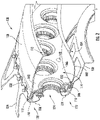
- FIG. 2 a close-up cross-sectional view is provided of the combustion section 26 of the exemplary turbofan engine 10 of FIG. 1 . More particularly, FIG. 2 provides a perspective, cross-sectional view of a combustor assembly 100, which may be positioned in the combustion section 26 of the exemplary turbofan engine 10 of FIG. 1 , in accordance with an exemplary embodiment of the present disclosure.
- the combustor assembly 100 generally includes an inner liner 102 extending between an aft end 104 and a forward end 106 generally along the axial direction A, as well as an outer liner 108 also extending between and aft end 110 and a forward end 112 generally along the axial direction A.
- the inner and outer liners 102, 108 together at least partially define a combustion chamber 114 therebetween.
- the inner and outer liners 102, 108 are each attached to an annular dome. More particularly, the combustor assembly 100 includes an inner annular dome 116 attached to the forward end 106 of the inner liner 102 and an outer annular dome 118 attached to the forward end 112 of the outer liner 108.
- the inner and outer annular domes 116, 118 are shown each including an enclosed surface defining a slot 122 for receipt of the forward ends 106, 112 of the respective inner and outer liners 102, 108, any suitable attachment scheme can be utilized to attach the liners to the respective domes.
- the exemplary combustor assembly 100 is shown including an inner and an outer annular dome, it is to be understood that in other embodiments, the dome may be formed as a single dome construction or any other suitable multi-dome construction (e.g., 3 domes, etc.).
- the combustor assembly 100 further includes a plurality of fuel air mixers 124 spaced along a circumferential direction within the outer dome 118. More particularly, the plurality of fuel air mixers 124 are disposed between the outer dome 118 and the inner dome 116 along the radial direction R. Compressed air from the compressor section of the turbofan engine 10 flows into or through the fuel air mixers 124, where the compressed air is mixed with fuel and ignited to create the combustion gases 66 within the combustion chamber 114.
- the inner and outer domes 116, 118 are configured to assist in providing such a flow of compressed air from the compressor section into or through the fuel air mixers 126.
- the outer dome 118 includes an outer cowl 126 at a forward end 128 and the inner dome 116 similarly includes an inner cowl 130 at a forward end 132.
- the outer cowl 126 and inner cowl 130 may assist in directing the flow of compressed air from the compressor section 26 into or through one or more of the fuel air mixers.
- the inner and outer domes 116, 118 each include attachment portions configured to assist in mounting the combustor assembly 100 within the turbofan engine 10.
- the outer dome 118 includes an attachment extension 134 configured to be mounted to an outer combustor casing (not shown) and the inner dome 116 includes a similar attachment extension 138 configured to attach to an annular support member (not shown) within the turbofan engine 10.
- the inner dome 116 may be formed integrally as a single annular component, and similarly, the outer dome 118 may also be formed integrally as a single annular component. It should be appreciated, however, that in other exemplary embodiments, the inner dome 116 and/or the outer dome 118 may alternatively be formed by one or more components joined in any suitable manner.
- the outer cowl 126 may be formed separately from the outer dome 118 and attached to the forward end 128 of the outer dome 118 using, e.g., a welding process.
- the attachment extension 134 may also be formed separately from the outer dome 118 and attached to the forward end 128 of the outer dome 118 using, e.g., a welding process.
- the inner dome 116 may have a similar configuration.
- the exemplary combustor assembly 100 further includes a plurality of heat shields 142 positioned around each fuel air mixer 124, arranged circumferentially.
- the heat shields 142 are attached to and extend between the outer dome 118 and the inner dome 116.
- the heat shields 142 are configured to protect certain components of the turbofan engine 10 from the relative extreme temperatures of the combustion chamber 114.
- each of the heat shield 142 inner liner 102 and outer liner 104 are exposed to relatively harsh conditions of relatively high temperatures during operation of the gas turbine engine.
- a thermal barrier coating 146 is present at least on the exposed surfaces of one or more of these components.
- the heat shields 142 include a thermal barrier coating 146 for protecting the underlying structure of the heat shields 142.
- the thermal barrier coating 146 may be a ceramic coating, or any other suitable coating.
- the thermal barrier coating 146 may generally include a ceramic thermal barrier material in one or more embodiments.
- suitable ceramic thermal barrier coating materials may include various types of oxides, such as aluminum oxide (“alumina”), hafnium oxide (“hafnia”), or zirconium oxide (“zirconia”), in particular stabilized hafnia or stabilized zirconia, and blends including one or both of these.
- stabilized zirconia examples include without limitation yttria-stabilized zirconia, ceria-stabilized zirconia, calcia-stabilized zirconia, scandiastabilized zirconia, magnesia-stabilized zirconia, india-stabilized zirconia, ytterbiastabilized zirconia, lanthana-stabilized zirconia, gadolinia-stabilized zirconia, as well as mixtures of such stabilized zirconia. Similar stabilized hafnia compositions are known in the art and suitable for use in embodiments described herein.
- the thermal barrier coating 146 may include yttria-stabilized zirconia.
- Suitable yttria-stabilized zirconia may include from about 1 weight percent to about 20 weight percent yttria (based on the combined weight of yttria and zirconia), and more typically from about 3 weight percent to about 10 weight percent yttria.
- An example of yttria-stabilized zirconia thermal barrier coating includes about 7% yttria and about 93% zirconia.
- zirconia may further include one or more of a second metal (e.g., a lanthanide, actinide, or the like) oxide, such as dysprosia, erbia, europia, gadolinia, neodymian, praseodymia, urania, and hafnia, to further reduce thermal conductivity of the thermal barrier coating material.
- the thermal barrier coating material may further include an additional metal oxide, such as titania and/or alumina.
- the thermal barrier coating 146 may be composed of 8YSZ, though higher yttria concentrations may be utilized.
- Suitable ceramic thermal barrier coating materials may also include pyrochlores of general formula A2B2O7 where A is a metal having a valence of 3+ or 2+ (e.g., gadolinium, aluminum, cerium, lanthanum, or yttrium) and B is a metal having a valence of 4+ or 5+ (e.g., hafnium, titanium, cerium, or zirconium) where the sum of the A and B valences is 7.
- Representative materials of this type include gadolinium zirconate, lanthanum titanate, lanthanum zirconate, yttrium zirconate, lanthanum hafnate, cerium hafnate, and lanthanum cerate.
- the thickness of the thermal barrier coating 146 may depend upon the substrate or the component it is deposited on. In some embodiments, the coating 146 has a thickness in a range of from about 25 micrometers ( ⁇ m) to about 2000 ⁇ m. In some embodiments, the coating 146 has a thickness in a range of from about 25 ⁇ m to about 1500 ⁇ m. In some embodiments, the thickness is in a range of from about 25 ⁇ m to about 1000 ⁇ m.
- the thermal barrier coating 146 may wear down or degrade more quickly than other portions of the thermal barrier coating 146.
- the thermal barrier coating 146 includes a worn portion 148 between adjacent fuel air mixers 124.
- the exemplary system 200 shown generally includes a nozzle 202 a mixture line 204 and a pressurized gas line 206.
- the mixture line 204 may provide a sprayable thermal barrier coating powder mixture 208 to the nozzle 202 and the pressurized gas line 206 may provide a flow of pressurized gas (such as a flow of pressurized air).
- the nozzle 202 may mix the flow of sprayable thermal barrier coating powder mixture 208 with the flow of pressurized gas to atomize the flow of sprayable thermal barrier coating powder mixture 208 and apply such thermal barrier coating powder mixture 208 to the worn portion 148 of the thermal barrier coating 146.
- the sprayable thermal barrier coating powder mixture 208 is configured to be applied directly to the worn portion 148 of the thermal barrier coating 146, an exposed portion of the underlying component, or both. More specifically, for the embodiment shown the sprayable thermal barrier coating powder mixture 208 is configured to be applied directly to the worn portion 148 of the thermal barrier coating 146, an exposed portion of the underlying component, or both without any intervening cleaning steps. In such a manner, the sprayable thermal barrier coating powder mixture 208 may be used to form a patch 150 to cover or fill in the worn portion 148 of the thermal barrier coating 146.
- this process may require minimal disassembly of the gas turbine engine components in order to undertake the coating restoration process, and that the coating may be applied to surfaces without requiring any special degreasing, cleaning or oxide removal that is typically required for many "in-shop” type repairs.
- the coating chemistry and the spray process may be engineered to restore coating with oxidized surfaces. This may eliminate the need for any sort of flash bond coat process that may otherwise be undertaken for "in-shop" type repair applications.
- the thermal barrier coating powder mixture 208, and system 200 for applying the same is configured to form a coating having a thickness 210 greater than 2 mils (i.e., thousandths of an inch), such as greater than 4 mils, such as greater than 6 mils, such as greater than 10 mils, such as greater than 15 mils, such as up to about 45 mils, such as up to about 35 mils, such as up to about 25 mils.
- the thermal barrier coating powder mixture 208 may form a repaired portion of the thermal barrier coating 146.
- the thickness 210 refers a maximum thickness of the repaired portion, or rather the maximum thickness of the patch 150.
- a close-up view of a sprayable thermal barrier coating powder mixture 208 is provided as may be utilized in the exemplary system 200 described above with reference to FIG.3 . It will be appreciated, however, that in other embodiments, the sprayable thermal barrier coating powder mixture 208 may instead be utilized with any other suitable system 200 capable of spraying the powder mixture 208 onto a component of a gas turbine engine (such as turbofan engine 10), or any other suitable gas turbine engine, in situ.
- a gas turbine engine such as turbofan engine 10
- the exemplary system 200 described above with reference to FIG.3 is depicted applying the sprayable thermal barrier coating powder mixture 208 to the thermal barrier coating 146 of the heat shield 142 within the combustion section 26 of the gas turbine engine 10
- the sprayable thermal barrier coating powder mixture 208 depicted in FIG.4 may be applied to or otherwise utilized to repair a thermal barrier coating 146 on one or more combustion chamber liners, one or more turbine rotor blades, one or more turbine stator vanes, etc.
- the system 200 for applying such sprayable thermal barrier coating powder mixture 208 may include any other suitable technology for providing the sprayable thermal barrier coating powder mixture 208 to the worn portion 148 of the thermal barrier coating 146.
- the sprayable thermal barrier coating powder mixture 208 generally includes a dry composition having a low surface area ceramic powder 214 and a high surface area ceramic powder 216.
- the term low surface area ceramic powder 214 refers to a ceramic powder having less than or equal to 10 meters squared of surface area per gram, such as less than or equal to 8 meters squared of surface area per gram, such as less than or equal to 5 meters squared of surface area per gram.
- high surface area ceramic powder 216 refers to a ceramic powder having greater than 10 meters squared of surface area per gram, such as greater than or equal to 15 meters squared of surface area per gram, and up to 400 meters squared of surface area per gram, such as up to 4000 meters squared of surface area per gram.
- ceramic powder refers to a powder including one or more refractory oxides, such as one or more alumina, zirconia, hafnia, magnesia, silica, yttria, and combinations thereof.
- the low surface area ceramic powder 214 and high surface area ceramic powder 216 may be formed of a material having substantially the same chemistry has a chemistry of a thermal barrier coating 146 to which is being applied.
- the low surface area ceramic powder 214 and high surface area ceramic powder 216 of the sprayable thermal barrier coating powder mixture 208 utilized may have substantially the same chemistry as the thermal barrier coating 146 being repaired.
- the powders 214, 216 and the thermal barrier coating 216 may each include at least 50% by weight of a common material or component.
- the low surface area ceramic powder 214, the high surface area ceramic powder 216, or both may have different suitable chemistries.
- the low surface area ceramic powder 214 may have a median particle size distribution greater than 5 microns and less than 50 microns, and the high surface area ceramic powder 216 may have a median particle size distribution smaller than 5 microns.
- the low surface area ceramic powder 214 may have a median particle size distribution greater than 8 microns and less than 40 microns, and the high surface area ceramic powder 216 may have a median particle size distribution smaller than 4 microns, such as smaller than 3 microns, such as at least 0.1 microns.
- the high surface area ceramic powder 216 may act as a binder to hold the powder mixture 208 together.
- the low surface area ceramic powder 214 may act as a filler.
- a thicker thermal barrier coating 146 in general a larger low surface area ceramic powder 214 may be used, and by contrast, when it is desired to apply thinner thermal barrier coating 146, in general a smaller low surface area ceramic powder 214 may be used.
- the sprayable thermal barrier coating powder mixture 208 may be configured to be sprayed on to the portion of the thermal barrier coating 146 and/or component to be repaired in situ and cured by exposure to operating temperatures within the gas turbine engine 10. In such a manner, the engine 10 may not need to be taken "off wing" and at least partially disassembled to allow the part being repaired to be put into a separate machine to cure a thermal barrier coating patch 150 applied thereto.
- the sprayable thermal barrier coating powder mixture 208 may include on or more portions that function as binders holding the powder mixture 208 together across a relatively wide temperature range (referred to herein as the "activation temperature range" of the sprayable thermal barrier coating powder mixture 208, described in more detail below).
- the sprayable thermal barrier coating powder mixture 208 may further include at least one binder additive 218 (depicted schematically as a triangle in FIG. 4 solely to distinguish from the high and low surface area ceramic powders 216, 214).
- the at least one binder additive 218 may be an organic binder additive.
- the organic binder additive may be one or more of: film forming polymeric binders such as polyvinyl alcohol, polyethylene oxide, poly ethylene glycol, polyvinylpyrrolidone (PVP), acrylates, acrylamides, and copolymers.
- Inclusion of the organic binder additive may function as a binder for the sprayable thermal barrier coating powder mixture 208 at a temperature range less than 500 degrees Celsius, such as between 100 degrees Celsius and 500 degrees Celsius.
- the at least one binder additive 218 may additionally or alternatively be an inorganic binder additive.
- the inorganic binder additive may be one or more high surface area (>10 m2/g) refractory oxides, such as one or more of alumina, zirconia, hafnia, silica, and yttria.
- Inclusion of the inorganic binder additive may function as a binder for the sprayable thermal barrier coating powder mixture 208 at a temperature range greater than 500 degrees Celsius, such as between 500 degrees Celsius and 1000 degrees Celsius, such as up to 1200 degrees Celsius, such as up to 1500 degrees Celsius.
- the sprayable thermal barrier coating powder mixture 208 such as a dry composition of the sprayable thermal barrier coating powder mixture 208 made up of the low surface area ceramic powder 214, the high surface area ceramic powder 216, and the binder additive(s) 218, if included, may together define an activation temperature range from at least 300 degrees Celsius to 1000 degrees Celsius, such as from 300 degrees Celsius to 1200 degrees, such as from Celsius 300 degrees Celsius to 1500 degrees Celsius.
- the term "activation temperature" for a particular component of the sprayable thermal barrier coating powder mixture 208 may refer to a temperature at which at least a portion of the particular component functions as a binder for other components of the sprayable thermal barrier coating powder mixture 208, and/or to the substrate to which the sprayable thermal barrier coating powder mixture 208 is applied.
- the term activation temperature refers to a temperature at which the component enters the onset of the first stage of sintering. At this temperature (the activation temperature) there is inter-material diffusion that causes "neck formation” or chemical adhesion between particles, such as between ceramic particles.
- chemical adhesion occurs at temperatures significantly below than a temperature of the engine when the engine is at takeoff speeds/ power level.
- activation temperature range refers to a temperature range across which at least a portion of at least one component of the sprayable thermal barrier coating powder mixture 208 functions as a binder for the sprayable thermal barrier coating powder mixture 208.
- the sprayable thermal barrier coating powder mixture 208 defines a cure temperature within or overlapping with the activation temperature range of the sprayable thermal barrier coating powder mixture 208.
- the high surface area ceramic powder 216 of the sprayable thermal barrier coating powder mixture 208 may define a cure temperature at least partially greater than 1000 degrees Celsius and less than an upper bound of the activation temperature range of the sprayable thermal barrier coating powder mixture 208, such as less than 1500 degrees Celsius.
- cure temperature refers to a temperature above which the sprayable thermal barrier coating powder mixture 208 begins to undergo a process whereby the sprayable thermal barrier coating powder mixture 208 begins a material and/or chemical diffusion.
- the sprayable thermal barrier coating powder mixture 208 may be applied to a portion of a thermal barrier coating 146 of a component an engine needing repair at a relatively low temperature, such as at a temperature between 0 degrees Celsius and 50 degrees Celsius.
- the sprayable thermal barrier coating powder mixture 208 may remain together in position on the worn portion 148 of the thermal barrier coating 146 through the temperatures of the engine 10 as the engine 10 starts up. Further, the sprayable thermal barrier coating powder mixture 208 may remain together in position on the worn portion 148 of the thermal barrier coating 146 until the engine 10 is operating at a temperature sufficient to cure the sprayable thermal barrier coating powder mixture 208 in position on the worn portion 148 of the thermal barrier coating 146 as a permanent patch 150 to the thermal barrier coating 146. In such a manner, the sprayable thermal barrier coating powder mixture 208 may be engine curable.
- the binder additive 218 may not make up a large portion of the dry composition of the sprayable thermal barrier coating powder mixture 208 (the "dry composition” referring to all parts of the sprayable thermal barrier coating powder mixture 208 that are in a solid phase).
- the low surface area ceramic powder 214 and high surface area ceramic powder 216 together makeup at least 80% by weight of the dry composition of the sprayable thermal barrier coating powder mixture 208.
- the low surface area ceramic powder 214 and high surface area ceramic powder 216 may together makeup at least 90% by weight of the dry composition of the sprayable thermal barrier coating powder mixture 208, such as at least 95% by weight of the dry composition of the sprayable thermal barrier coating powder mixture 208.
- the resulting thermal barrier coating patch 150 may still be formed substantially of high temperature resistant ceramic materials.
- the low surface area ceramic powder 214 may make up at least 50% by weight of the dry composition of the sprayable thermal barrier coating powder mixture.
- the low surface area ceramic powder 214 may make up at least 60% by weight of the dry composition, such as at least 70% by weight of the dry composition, such as up to 90% by weight of the dry composition.
- the sprayable thermal barrier coating powder mixture 208 is "sprayable.”
- the sprayable thermal barrier coating powder mixture 208 defines a flowability that facilitates it being sprayed with, e.g., a carrier gas, a high pressure gas source, etc.
- the sprayable thermal barrier coating powder mixture 208 may be sprayed to a substrate, such as applied to the worn portion 148 of the thermal barrier coating 146, by atomizing the mixture with a high pressure gas.
- the sprayable thermal barrier coating powder mixture 208 further includes a liquid 220 added to the dry composition to form a slurry for spraying the mixture.
- the liquid may be configured to dry quickly during the application process.
- the liquid may include a low boiling point liquid, such as a liquid alcohol, liquid ethanol, liquid carbon dioxide, etc.
- the low boiling point liquid may define a boiling point less than 100 degrees Celsius, such as less than 50 degrees Celsius, such as less than 0 degrees Celsius, such as greater than absolute 0.
- the liquid 220 added to the dry composition to form the sprayable thermal barrier coating powder mixture 208 may be additionally or alternatively be a high vapor pressure fluid.
- the liquid 220 may define a vapor pressure greater than or equal to 2.3 kPascals (kPa) at 20 degrees Celsius, such as greater than or equal to 4 kPa at 20 degrees Celsius, such as greater than or equal to 5.5 kPa at 20 degrees Celsius, such as up to 1,000 kPa at 20 degrees Celsius.
- a low boiling point liquid/ high vapor pressure fluid may allow for the sprayable thermal barrier coating powder mixture 208 to flow to the nozzle 202 to be applied to the thermal barrier coating 146 or other component, such that the thermal barrier coating 146 or other component may be repaired in situ, but may evaporate relatively quickly to facilitate engine curing of the sprayable thermal barrier coating powder mixture 208.
- the sprayable thermal barrier coating powder mixture 208 may define a solids loading between 30% and 80% (i.e., a percentage by weight of the dry composition portion of the sprayable thermal barrier coating powder mixture 208 to a wet composition portion of the sprayable thermal barrier coating powder mixture 208 - which for the embodiment discussed is the drying agent).
- the sprayable thermal barrier coating powder mixture 208 may define a specific gravity between about 0.8 grams per cubic centimeter and 3 grams per cubic centimeter, such as between about 1 gram per cubic centimeter and 2.7 grams per cubic centimeter.
- a slurry having such a solids loading and specific gravity may reduce a particle settling during a spraying process (including a pumping process), and further may reduce separation, agglomeration, reaction, polymerization etc. Moreover, such a configuration may ensure the slurry/ mixture 208 is pumpable through relatively small tubes, such as through tubes having a diameter less than 0.1 inches, such as less than 0.075 inches, such as less than 0.06 inches (e.g., tube 204).
- the sprayable thermal barrier coating powder mixture 208 may generally be formed in accordance with one or more of the following examples:
- a sprayable thermal barrier coating powder mixture 208 including:
- a sprayable thermal barrier coating powder mixture 208 including:
- the prepared slurry was used to repair laboratory coupons with engine simulated distress.
- the slurries were delivered through tubes to a gas atomized spray nozzle and sprayed using a process that mimics an on-wing configuration setup.
- the repaired samples were cured simulating engine operation and tested to determine coating durability.
- the coupons were tested in two different methods to simulate engine environment.
- the first method was a jet engine thermal shock (JETS) test.
- JETS jet engine thermal shock
- the thermal shock testing simulates the thermal cycling that components experience in the turbine section of aircraft turbomachinery in general operation.
- the second method was a furnace cycle test (FCT).
- FCT furnace cycle test
- the exemplary sprayable thermal barrier coating powder mixture 208 described above is by way of example only.
- the sprayable thermal barrier coating powder mixture 208 may have any other suitable configuration.
- the low surface area ceramic powder 214 may additionally or alternatively be a low surface area ceramic powder precursor.
- the low surface area ceramic powder precursor may be a silicone, a titanium-based composition, or phosphate-based composition that thermally decomposes to form a refractory oxide to be used as the low surface area ceramic powder 214. Such may occur after the sprayable thermal barrier coating powder mixture 208 is applied to a substrate.
- a coating formed using a sprayable thermal barrier coating powder mixture 208 in accordance with one or more of these configurations may result in a coating having a relatively high thermal resistance/ low thermal conductivity, that may attach directly to a component 252 surface without requiring any special degreasing, gleaning, or oxide removal.
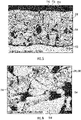
- FIGS. 5 and 6 close-up, cross-sectional views are provided of a repaired coating 250 applied to a surface of an underlying component 252.
- FIG. 5 shows a close-up, cross-sectional view of a repaired coating 250 applied to the surface of an underlying component 252
- FIG. 6 shows a close of view of a portion of the repaired coating 250 of FIG. 5 .
- the repaired coating 250 is formed of a sprayable thermal barrier coating powder mixture 208 in accordance with one or more exemplary aspects of the present disclosure, such as one or more of the exemplary aspects described above.
- the repaired coating 250 includes low surface area ceramic powder 214 and high surface area ceramic powder 216.
- the repaired coating 250 defines a plurality of pores 254, such that it defines a porosity for improved thermal protection/ a decreased thermal conductivity.
- the exemplary coating 250 formed using the sprayable thermal barrier coating powder mixture 208 in accordance with one or more of the above configurations may result in a coating 250 having an engineered porosity that provides a desired amount of thermal protection with a relatively thin restored coating 250.
- a thermal conductivity of the restored coating 250 shown in FIGS. 5 and 6 can be tailored and may be between 0.4 Watts/meters-Kelvin and 2 Watts/meters-Kelvin, each at 1000 degrees C.
- the thermal conductivity of the restored coating 250 shown in FIGS. 5 and 6 can be tailored by modifying the porosity and maximum pore size within the coating 250.
- maximum pore size refers to a greatest cross-wise measurement of a particular pore 254.
- the maximum pore size resulting from the low surface area ceramic powder 214 may be less than or equal to 15 microns, and the maximum pore size resulting from the high surface area ceramic powder 216 may be less than or equal to 1 micron.
- the coating 250 requirements to completely insulate the underlying material may be less than the original coating 250. Thinner coating 250 may result in lower in-plane stresses and allows for engine curing of the coating 250.
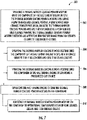
- a method 300 for repairing a thermal barrier coating of a component of a gas turbine engine in situ is provided.
- the method 300 may utilize one or more of the exemplary aspects of a sprayable thermal barrier coating powder mixture described above. Further, the method 300 may be utilized on one or more of the exemplary components or engines described above, or alternatively may be utilized on any other suitable component, engine, or elsewhere.
- the method 300 of FIG. 7 includes at (302) spraying a thermal barrier coating powder mixture onto the component of the gas turbine engine in situ, the thermal barrier coating powder mixture including a low surface area ceramic powder, a low surface area ceramic powder precursor, or both, the thermal barrier coating powder mixture further including a high surface area ceramic powder, the thermal barrier coating powder mixture defining an activation temperature range from 300 degrees Celsius to 1200 degrees Celsius.
- spraying the thermal barrier coating powder mixture onto the component of the gas turbine engine in situ at (302) may include spraying the thermal barrier coating powder mixture onto the component of the gas turbine engine with the component is installed within the gas turbine engine, while the gas turbine engine is substantially assembly (e.g., is at least 80% assembled), while the gas turbine engine is mounted to a vehicle (such as a wing or fuselage of an aircraft), or a combination thereof.
- spraying the thermal barrier coating powder mixture onto the component of the gas turbine engine in situ at (302) includes at (304) spraying the thermal barrier coating powder mixture onto the component of the gas turbine engine in situ to a thickness greater than 2 mils (i.e., thousandths of an inch) and less than 25 mils.
- spraying the thermal barrier coating powder mixture onto the component of the gas turbine engine in situ at (302) includes at (306) spraying the thermal barrier coating powder mixture onto the component of the gas turbine engine in situ using a pressurized gas source.
- spraying the thermal barrier coating powder mixture onto the component of the gas turbine engine in situ at (302) may include atomizing the thermal barrier coating powder mixture.
- the pressurized gas may be any suitable carrier gas, such as an argon or air.
- the method 300 further includes at (308) operating the gas turbine engine to cure the thermal barrier coating powder mixture on the component.
- spraying the thermal barrier coating powder mixture onto the component of the gas turbine engine in situ at (302) may include spraying the thermal barrier coating powder mixture onto the component of the gas turbine engine in situ while the engine in not operating and is at a temperature below, e.g., 100 degrees Celsius, such as below 50 degrees Celsius.
- operating the gas turbine engine to cure the thermal barrier coating powder mixture on the component at (308) may include operating the gas turbine engine to cure the thermal barrier coating powder mixture on the component after spraying the thermal barrier coating powder mixture onto the component of the gas turbine engine in situ at (302).
- operating the gas turbine engine to cure the thermal barrier coating powder mixture on the component at (308) includes at (310) exposing the thermal barrier coating powder mixture on the component to operational temperatures between 1000 degrees Celsius and 1500 degrees Celsius.
- a sprayable thermal barrier coating powder mixture for a gas turbine engine comprising: a dry composition comprising a low surface area ceramic powder having a median particle size distribution greater than 5 microns and less than 50 microns, and a high surface area ceramic powder having a median particle size distribution smaller than 5 microns, wherein the low surface area ceramic powder makes up at least 50% by weight of the dry composition of the sprayable thermal barrier coating powder mixture.
- the dry composition further comprises at least one binder additive, wherein the low surface area ceramic powder, the high surface area ceramic powder, and the at least one binder additive together define an activation temperature range from at least 300 degrees Celsius to 1200 degrees Celsius.
- a method for repairing a thermal barrier coating of a component of a gas turbine engine in situ comprising: spraying a thermal barrier coating powder mixture onto the component of the gas turbine engine in situ, the thermal barrier coating powder mixture comprising a low surface area ceramic powder, a low surface area ceramic powder precursor, or both, the thermal barrier coating powder mixture further comprising a high surface area ceramic powder, the thermal barrier coating powder mixture defining an activation temperature range from 300 degrees Celsius to 1200 degrees Celsius; and operating the gas turbine engine to cure the thermal barrier coating powder mixture on the component.
- operating the gas turbine engine to cure the thermal barrier coating powder mixture on the component comprises exposing the thermal barrier coating powder mixture on the component to operational temperatures between 1000 degrees Celsius and 1500 degrees Celsius.
- spraying the thermal barrier coating powder mixture onto the component of the gas turbine engine in situ comprises spraying the thermal barrier coating powder mixture onto the component of the gas turbine engine in situ to a thickness greater than 2 mils and less than 25 mils.
- spraying the thermal barrier coating powder mixture onto the component of the gas turbine engine in situ comprises spraying the thermal barrier coating powder mixture onto the component of the gas turbine engine in situ using a pressurized gas source.
- spraying the thermal barrier coating powder mixture onto the component of the gas turbine engine in situ comprises spraying the thermal barrier coating powder mixture onto the component of the gas turbine engine in situ through one or more tubes having a diameter less than or equal to 0.06 inches.
- the thermal barrier coating powder mixture further comprises a drying agent to form a slurry, and wherein the drying agent comprises ethanol and a low boiling point liquid.
- the thermal barrier coating powder mixture comprises the low surface area ceramic powder, and wherein the low surface area ceramic powder and high surface area ceramic powder together makeup at least 80% by weight of a dry composition of the sprayable thermal barrier coating powder mixture.
- a sprayable thermal barrier coating powder mixture for a gas turbine engine comprising: a dry composition comprising a low surface area ceramic powder, a low surface area ceramic powder precursor, or both and a high surface area ceramic powder, the dry composition defining an activation temperature range from at least 300 degrees Celsius to 1200 degrees Celsius such that the thermal barrier coating powder mixture is configured to be sprayed on in situ and cured by exposure to operating temperatures within the gas turbine engine.
- the low surface area ceramic powder if included, has less than 5 meters squared of surface area per gram
- the low surface area ceramic powder precursor if included, is configured to form a powder having less than 5 meters squared of surface area per gram
- the high surface area ceramic powder has greater than 10 meters squared of surface area per gram and less than 4,000 meters squared of surface area per gram.
Landscapes
- Chemical & Material Sciences (AREA)
- Engineering & Computer Science (AREA)
- Ceramic Engineering (AREA)
- Materials Engineering (AREA)
- Organic Chemistry (AREA)
- Manufacturing & Machinery (AREA)
- Mechanical Engineering (AREA)
- Structural Engineering (AREA)
- Inorganic Chemistry (AREA)
- Chemical Kinetics & Catalysis (AREA)
- Metallurgy (AREA)
- General Engineering & Computer Science (AREA)
- Physics & Mathematics (AREA)
- Composite Materials (AREA)
- Thermal Sciences (AREA)
- General Chemical & Material Sciences (AREA)
- Plasma & Fusion (AREA)
- Coating By Spraying Or Casting (AREA)
- Turbine Rotor Nozzle Sealing (AREA)
Applications Claiming Priority (3)
| Application Number | Priority Date | Filing Date | Title |
|---|---|---|---|
| IN202011025995 | 2020-06-19 | ||
| US17/313,538 US11655720B2 (en) | 2020-06-19 | 2021-05-06 | Methods and materials for repairing a thermal barrier coating of a gas turbine component |
| EP21175663.0A EP3936491A3 (fr) | 2020-06-19 | 2021-05-25 | Procédés et matériaux de réparation d'un revêtement barrière thermique d'un composant de turbine à gaz |
Related Parent Applications (2)
| Application Number | Title | Priority Date | Filing Date |
|---|---|---|---|
| EP21175663.0A Division EP3936491A3 (fr) | 2020-06-19 | 2021-05-25 | Procédés et matériaux de réparation d'un revêtement barrière thermique d'un composant de turbine à gaz |
| EP21175663.0A Division-Into EP3936491A3 (fr) | 2020-06-19 | 2021-05-25 | Procédés et matériaux de réparation d'un revêtement barrière thermique d'un composant de turbine à gaz |
Publications (1)
| Publication Number | Publication Date |
|---|---|
| EP4008701A1 true EP4008701A1 (fr) | 2022-06-08 |
Family
ID=76098850
Family Applications (2)
| Application Number | Title | Priority Date | Filing Date |
|---|---|---|---|
| EP22152828.4A Pending EP4008701A1 (fr) | 2020-06-19 | 2021-05-25 | Procédés et matériaux de réparation d'un revêtement barrière thermique d'un composant de turbine à gaz |
| EP21175663.0A Pending EP3936491A3 (fr) | 2020-06-19 | 2021-05-25 | Procédés et matériaux de réparation d'un revêtement barrière thermique d'un composant de turbine à gaz |
Family Applications After (1)
| Application Number | Title | Priority Date | Filing Date |
|---|---|---|---|
| EP21175663.0A Pending EP3936491A3 (fr) | 2020-06-19 | 2021-05-25 | Procédés et matériaux de réparation d'un revêtement barrière thermique d'un composant de turbine à gaz |
Country Status (2)
| Country | Link |
|---|---|
| EP (2) | EP4008701A1 (fr) |
| CN (2) | CN119980124A (fr) |
Cited By (1)
| Publication number | Priority date | Publication date | Assignee | Title |
|---|---|---|---|---|
| WO2025116982A3 (fr) * | 2023-07-06 | 2025-10-16 | Rtx Corporation | Atténuation in situ de cmas de moteur à turbine |
Families Citing this family (2)
| Publication number | Priority date | Publication date | Assignee | Title |
|---|---|---|---|---|
| CN117644478B (zh) * | 2024-01-30 | 2024-05-17 | 西安格美金属材料有限公司 | 飞机多级增压喷气发动机的性能提升方法 |
| CN118857760B (zh) * | 2024-09-23 | 2025-01-14 | 国营川西机器厂 | 导向器排气面积测量数据控制方法 |
Citations (5)
| Publication number | Priority date | Publication date | Assignee | Title |
|---|---|---|---|---|
| US6413578B1 (en) * | 2000-10-12 | 2002-07-02 | General Electric Company | Method for repairing a thermal barrier coating and repaired coating formed thereby |
| US20040214938A1 (en) * | 2003-04-22 | 2004-10-28 | Ruud James A. | In-situ method and composition for repairing a thermal barrier coating |
| US6827969B1 (en) * | 2003-12-12 | 2004-12-07 | General Electric Company | Field repairable high temperature smooth wear coating |
| US20050228098A1 (en) * | 2004-04-07 | 2005-10-13 | General Electric Company | Field repairable high temperature smooth wear coating |
| US20180050964A1 (en) * | 2016-08-22 | 2018-02-22 | General Electric Company | Thermal barrier coating repair compositions and methods of use thereof |
Family Cites Families (4)
| Publication number | Priority date | Publication date | Assignee | Title |
|---|---|---|---|---|
| DE19623587A1 (de) * | 1996-06-13 | 1997-12-18 | Dlr Deutsche Forschungsanstalt | Keramische Verdampfermaterialien |
| DE102004036602A1 (de) * | 2004-07-28 | 2006-03-23 | Degussa Ag | Hochgefüllte, wässerige Metalloxid-Dispersion |
| BR112014015249B1 (pt) * | 2011-12-19 | 2021-04-13 | Praxair S.T. Technology, Inc | Composição de pasta fluida aquosa |
| US20190316246A1 (en) * | 2018-04-17 | 2019-10-17 | General Electric Company | Reactive phase spray formulation coatings |
-
2021
- 2021-05-25 EP EP22152828.4A patent/EP4008701A1/fr active Pending
- 2021-05-25 EP EP21175663.0A patent/EP3936491A3/fr active Pending
- 2021-06-18 CN CN202510235954.9A patent/CN119980124A/zh active Pending
- 2021-06-18 CN CN202110680836.0A patent/CN113816750A/zh active Pending
Patent Citations (5)
| Publication number | Priority date | Publication date | Assignee | Title |
|---|---|---|---|---|
| US6413578B1 (en) * | 2000-10-12 | 2002-07-02 | General Electric Company | Method for repairing a thermal barrier coating and repaired coating formed thereby |
| US20040214938A1 (en) * | 2003-04-22 | 2004-10-28 | Ruud James A. | In-situ method and composition for repairing a thermal barrier coating |
| US6827969B1 (en) * | 2003-12-12 | 2004-12-07 | General Electric Company | Field repairable high temperature smooth wear coating |
| US20050228098A1 (en) * | 2004-04-07 | 2005-10-13 | General Electric Company | Field repairable high temperature smooth wear coating |
| US20180050964A1 (en) * | 2016-08-22 | 2018-02-22 | General Electric Company | Thermal barrier coating repair compositions and methods of use thereof |
Non-Patent Citations (1)
| Title |
|---|
| WALDBILLIG D ET AL: "Effect of suspension plasma spraying process parameters on YSZ coating microstructure and permeability", SURFACE AND COATINGS TECHNOLOGY, ELSEVIER, NL, vol. 205, no. 23, 10 June 2011 (2011-06-10), pages 5483 - 5492, XP028248947, ISSN: 0257-8972, [retrieved on 20110617], DOI: 10.1016/J.SURFCOAT.2011.06.019 * |
Cited By (1)
| Publication number | Priority date | Publication date | Assignee | Title |
|---|---|---|---|---|
| WO2025116982A3 (fr) * | 2023-07-06 | 2025-10-16 | Rtx Corporation | Atténuation in situ de cmas de moteur à turbine |
Also Published As
| Publication number | Publication date |
|---|---|
| CN119980124A (zh) | 2025-05-13 |
| EP3936491A3 (fr) | 2022-03-16 |
| EP3936491A2 (fr) | 2022-01-12 |
| CN113816750A (zh) | 2021-12-21 |
Similar Documents
| Publication | Publication Date | Title |
|---|---|---|
| CN110199101B (zh) | 冷却核心燃气涡轮发动机 | |
| JP5802390B2 (ja) | 障壁コーティングを補修する方法 | |
| EP4008701A1 (fr) | Procédés et matériaux de réparation d'un revêtement barrière thermique d'un composant de turbine à gaz | |
| US10196982B2 (en) | Gas turbine engine having a flow control surface with a cooling conduit | |
| CN107043935A (zh) | 修理燃气涡轮构件的热屏蔽涂层的方法和所得的构件 | |
| EP3081764A1 (fr) | Porosité de revêtement variable pour influencer une durabilité de rotor et virole | |
| JP2011507789A (ja) | 障壁コーティング組成物を含むテープ及びこれを含む構成部品 | |
| US11913645B2 (en) | Combustor assembly for a turbine engine | |
| CN106906471A (zh) | 具有改进的隔热涂层系统的燃气涡轮构件 | |
| US11655720B2 (en) | Methods and materials for repairing a thermal barrier coating of a gas turbine component | |
| US20230330700A1 (en) | Thermal barrier coatings | |
| CN107091124B (zh) | 用于在涡轮叶片上同时沉积多个涂层的系统和方法 | |
| US11796176B2 (en) | Combustor assembly for a turbine engine | |
| US11753713B2 (en) | Methods for coating a component | |
| US11724969B2 (en) | Coating for improved surface finish | |
| US11034842B2 (en) | Coating for improved surface finish | |
| EP4261322A1 (fr) | Revêtements formant barrière thermique fissurée verticalement et compositions | |
| EP4253599A1 (fr) | Boue de zircone stabilisée à l'yttrium et ses procédés d'application | |
| US20230312935A1 (en) | Yttria-stabilized zirconia slurry and methods of application thereof | |
| US20250257694A1 (en) | Gas turbine engine | |
| CN116892422A (zh) | 氧化钇稳定的氧化锆浆料及其施加方法 | |
| US11649732B2 (en) | Vane assembly with spring device for biasing mate face seal | |
| US20250073829A1 (en) | System and method of repairing a multi-layer component of an engine | |
| EP4517044A1 (fr) | Système et procédé de réparation d'un composant multicouche d'un moteur | |
| CN107097035A (zh) | 用于使燃气涡轮发动机的有涂层构件复原的系统和方法 |
Legal Events
| Date | Code | Title | Description |
|---|---|---|---|
| PUAI | Public reference made under article 153(3) epc to a published international application that has entered the european phase |
Free format text: ORIGINAL CODE: 0009012 |
|
| STAA | Information on the status of an ep patent application or granted ep patent |
Free format text: STATUS: THE APPLICATION HAS BEEN PUBLISHED |
|
| AC | Divisional application: reference to earlier application |
Ref document number: 3936491 Country of ref document: EP Kind code of ref document: P |
|
| AK | Designated contracting states |
Kind code of ref document: A1 Designated state(s): AL AT BE BG CH CY CZ DE DK EE ES FI FR GB GR HR HU IE IS IT LI LT LU LV MC MK MT NL NO PL PT RO RS SE SI SK SM TR |
|
| STAA | Information on the status of an ep patent application or granted ep patent |
Free format text: STATUS: REQUEST FOR EXAMINATION WAS MADE |
|
| 17P | Request for examination filed |
Effective date: 20221205 |
|
| RBV | Designated contracting states (corrected) |
Designated state(s): AL AT BE BG CH CY CZ DE DK EE ES FI FR GB GR HR HU IE IS IT LI LT LU LV MC MK MT NL NO PL PT RO RS SE SI SK SM TR |
|
| STAA | Information on the status of an ep patent application or granted ep patent |
Free format text: STATUS: EXAMINATION IS IN PROGRESS |
|
| 17Q | First examination report despatched |
Effective date: 20250701 |