EP4008806A1 - Procédés et systèmes de détection de contamination dans des cellules d'électrolyse - Google Patents
Procédés et systèmes de détection de contamination dans des cellules d'électrolyse Download PDFInfo
- Publication number
- EP4008806A1 EP4008806A1 EP21210902.9A EP21210902A EP4008806A1 EP 4008806 A1 EP4008806 A1 EP 4008806A1 EP 21210902 A EP21210902 A EP 21210902A EP 4008806 A1 EP4008806 A1 EP 4008806A1
- Authority
- EP
- European Patent Office
- Prior art keywords
- synthetic
- cell
- time
- contamination
- real
- Prior art date
- Legal status (The legal status is an assumption and is not a legal conclusion. Google has not performed a legal analysis and makes no representation as to the accuracy of the status listed.)
- Granted
Links
Images






Classifications
-
- C—CHEMISTRY; METALLURGY
- C25—ELECTROLYTIC OR ELECTROPHORETIC PROCESSES; APPARATUS THEREFOR
- C25B—ELECTROLYTIC OR ELECTROPHORETIC PROCESSES FOR THE PRODUCTION OF COMPOUNDS OR NON-METALS; APPARATUS THEREFOR
- C25B1/00—Electrolytic production of inorganic compounds or non-metals
- C25B1/01—Products
- C25B1/34—Simultaneous production of alkali metal hydroxides and chlorine, oxyacids or salts of chlorine, e.g. by chlor-alkali electrolysis
- C25B1/46—Simultaneous production of alkali metal hydroxides and chlorine, oxyacids or salts of chlorine, e.g. by chlor-alkali electrolysis in diaphragm cells
-
- C—CHEMISTRY; METALLURGY
- C25—ELECTROLYTIC OR ELECTROPHORETIC PROCESSES; APPARATUS THEREFOR
- C25B—ELECTROLYTIC OR ELECTROPHORETIC PROCESSES FOR THE PRODUCTION OF COMPOUNDS OR NON-METALS; APPARATUS THEREFOR
- C25B15/00—Operating or servicing cells
- C25B15/02—Process control or regulation
- C25B15/023—Measuring, analysing or testing during electrolytic production
-
- C—CHEMISTRY; METALLURGY
- C25—ELECTROLYTIC OR ELECTROPHORETIC PROCESSES; APPARATUS THEREFOR
- C25B—ELECTROLYTIC OR ELECTROPHORETIC PROCESSES FOR THE PRODUCTION OF COMPOUNDS OR NON-METALS; APPARATUS THEREFOR
- C25B15/00—Operating or servicing cells
- C25B15/02—Process control or regulation
- C25B15/023—Measuring, analysing or testing during electrolytic production
- C25B15/025—Measuring, analysing or testing during electrolytic production of electrolyte parameters
- C25B15/029—Concentration
- C25B15/031—Concentration pH
-
- C—CHEMISTRY; METALLURGY
- C25—ELECTROLYTIC OR ELECTROPHORETIC PROCESSES; APPARATUS THEREFOR
- C25B—ELECTROLYTIC OR ELECTROPHORETIC PROCESSES FOR THE PRODUCTION OF COMPOUNDS OR NON-METALS; APPARATUS THEREFOR
- C25B9/00—Cells or assemblies of cells; Constructional parts of cells; Assemblies of constructional parts, e.g. electrode-diaphragm assemblies; Process-related cell features
- C25B9/70—Assemblies comprising two or more cells
-
- G—PHYSICS
- G05—CONTROLLING; REGULATING
- G05B—CONTROL OR REGULATING SYSTEMS IN GENERAL; FUNCTIONAL ELEMENTS OF SUCH SYSTEMS; MONITORING OR TESTING ARRANGEMENTS FOR SUCH SYSTEMS OR ELEMENTS
- G05B23/00—Testing or monitoring of control systems or parts thereof
- G05B23/02—Electric testing or monitoring
- G05B23/0205—Electric testing or monitoring by means of a monitoring system capable of detecting and responding to faults
- G05B23/0218—Electric testing or monitoring by means of a monitoring system capable of detecting and responding to faults characterised by the fault detection method dealing with either existing or incipient faults
- G05B23/0224—Process history based detection method, e.g. whereby history implies the availability of large amounts of data
- G05B23/0227—Qualitative history assessment, whereby the type of data acted upon, e.g. waveforms, images or patterns, is not relevant, e.g. rule based assessment; if-then decisions
- G05B23/0235—Qualitative history assessment, whereby the type of data acted upon, e.g. waveforms, images or patterns, is not relevant, e.g. rule based assessment; if-then decisions based on a comparison with predetermined threshold or range, e.g. "classical methods", carried out during normal operation; threshold adaptation or choice; when or how to compare with the threshold
-
- G—PHYSICS
- G05—CONTROLLING; REGULATING
- G05B—CONTROL OR REGULATING SYSTEMS IN GENERAL; FUNCTIONAL ELEMENTS OF SUCH SYSTEMS; MONITORING OR TESTING ARRANGEMENTS FOR SUCH SYSTEMS OR ELEMENTS
- G05B23/00—Testing or monitoring of control systems or parts thereof
- G05B23/02—Electric testing or monitoring
- G05B23/0205—Electric testing or monitoring by means of a monitoring system capable of detecting and responding to faults
- G05B23/0218—Electric testing or monitoring by means of a monitoring system capable of detecting and responding to faults characterised by the fault detection method dealing with either existing or incipient faults
- G05B23/0224—Process history based detection method, e.g. whereby history implies the availability of large amounts of data
- G05B23/024—Quantitative history assessment, e.g. mathematical relationships between available data; Functions therefor; Principal component analysis [PCA]; Partial least square [PLS]; Statistical classifiers, e.g. Bayesian networks, linear regression or correlation analysis; Neural networks
-
- G—PHYSICS
- G06—COMPUTING OR CALCULATING; COUNTING
- G06F—ELECTRIC DIGITAL DATA PROCESSING
- G06F30/00—Computer-aided design [CAD]
- G06F30/20—Design optimisation, verification or simulation
- G06F30/27—Design optimisation, verification or simulation using machine learning, e.g. artificial intelligence, neural networks, support vector machines [SVM] or training a model
-
- G—PHYSICS
- G06—COMPUTING OR CALCULATING; COUNTING
- G06N—COMPUTING ARRANGEMENTS BASED ON SPECIFIC COMPUTATIONAL MODELS
- G06N3/00—Computing arrangements based on biological models
- G06N3/02—Neural networks
- G06N3/04—Architecture, e.g. interconnection topology
-
- G—PHYSICS
- G06—COMPUTING OR CALCULATING; COUNTING
- G06N—COMPUTING ARRANGEMENTS BASED ON SPECIFIC COMPUTATIONAL MODELS
- G06N3/00—Computing arrangements based on biological models
- G06N3/02—Neural networks
- G06N3/08—Learning methods
-
- G—PHYSICS
- G06—COMPUTING OR CALCULATING; COUNTING
- G06F—ELECTRIC DIGITAL DATA PROCESSING
- G06F2119/00—Details relating to the type or aim of the analysis or the optimisation
- G06F2119/08—Thermal analysis or thermal optimisation
Definitions
- the present disclosure relates generally to electrolysis processes, where a contamination of the feed electrolytes causes a change in cell voltage or efficiency of the electrochemical reaction and more particularly to the real-time detection of membrane, cell separator and electrode poisoning or performance degradation by contaminants as well as any harmful operating conditions in Chlor-Alkali, water electrolysis, fuel cells or any other industrial electrolysis cells.
- Chlor-Alkali consist of decomposing a lower value chemical (e.g. NaCl, KCI, HCI) into a higher value chemical (e.g. NaOH, Cl 2 , KOH) by applying a direct electrical current. This reaction take place in an electrochemical cell. In an industrial setting, several cells are combined in series or parallel to perform the reaction. This combination is called an electrolyzer.
- a lower value chemical e.g. NaCl, KCI, HCI
- a higher value chemical e.g. NaOH, Cl 2 , KOH
- a method for detecting contamination and harmful operating conditions in a cell of an electrolyzer having a plurality of cells comprises recording real-time data from the cells during operation of the electrolyzer; generating synthetic data based on historical data of the electrolyzer and the cells, the synthetic data comprising synthetic cell voltages and synthetic product output flow, synthetic anolyte pH, feed brine pH, or oxygen in chlorine gas concentration of the electrolyzer; determining cell-specific k-factors or U 0 from the historical data; detecting a slow contamination and harmful operating conditions when a difference between the synthetic product flow output, synthetic anolyte pH, feed brine pH, or oxygen in chlorine gas concentration and a real-time product output flow, anolyte pH, feed brine pH, or oxygen in chlorine gas concentration exceeds a first threshold; and detecting a fast contamination and harmful operating conditions when the cell-specific k-factors or U 0 exceed a second threshold and a trend of a difference between the synthetic cell voltages
- detecting the slow contamination or the fast contamination comprises triggering an alarm.
- the synthetic data is determined using predictive models that take into account normal cell degradation based on cell-specific parameters and process data.
- the cell-specific k-factors or U 0 are determined using linear model regression.
- the slow contamination is a slow feed electrolytes contamination of an electrolysis cell
- the fast contamination is a fast feed electrolytes contamination of an electrolysis cell
- the conditional logic rule is triggered when the difference between the synthetic cell voltages and real-time cell voltages exceeds a third threshold.
- the method is triggered when the electrolyzer is newly deployed at a production site or an accuracy of deployed predictive models is lower than a fourth threshold.
- the historical data represents non faulty electrolyzer operation at a stable current load.
- parameters used for generating the synthetic data are estimated using neural networks, nonlinear multivariate techniques, or switching Kalman filters.
- an assembly comprising a plurality of electrolysis cells forming one or more electrolyzers and a fault detection system.
- the fault detection system comprises at least one computing device operatively coupled to the one or more electrolyzers, the at least one computing device comprising at least one processing unit and a non-transitory computer readable medium having stored thereon program instructions.
- the program instructions are executable by the at least one processing unit for recording real-time data from the cells during operation of the one or more electrolyzers; generating synthetic data based on historical data of the one or more electrolyzers and the cells, the synthetic data comprising synthetic cell voltages and synthetic product output flow, synthetic anolyte pH, feed brine pH, or oxygen in chlorine gas concentration of the one or more electrolyzers; determining cell-specific k-factors or U 0 from the historical data; detecting a slow contamination and harmful operating conditions when a difference between the synthetic product output flow, synthetic anolyte pH, feed brine pH, or oxygen in chlorine gas concentration and a real-time product output flow, anolyte pH, feed brine pH, or oxygen in chlorine gas concentration exceeds a first threshold; and detecting a fast contamination and harmful operating conditions when the cell-specific k-factors or U 0 exceed a second threshold and a trend of a difference between the synthetic cell voltages and real-time cell voltages or a derivative of the difference meets or
- detecting the slow contamination or the fast contamination comprises triggering an alarm.
- the synthetic data is determined using predictive models that take into account normal cell degradation based on cell-specific parameters and process data.
- the cell-specific k-factors or U 0 are determined using linear model regression.
- the slow contamination is a slow feed electrolytes contamination of an electrolysis cell
- the fast contamination is a fast feed electrolytes contamination of an electrolysis cell
- the conditional logic rule is triggered when the difference between the synthetic cell voltages and real-time cell voltages exceeds a third threshold.
- the fault detection system is triggered when the one or more electrolyzers are newly deployed at a production site or an accuracy of deployed predictive models is lower than a fourth threshold.
- the historical data represents non faulty electrolyzer operation at a stable current load.
- parameters used for generating the synthetic data are estimated using neural networks, nonlinear multivariate techniques, or switching Kalman filters.
- a treatment process is carried out with the following main steps: saturation, precipitation, clarification, filtration, polishing filtration, ion exchange electrolysis, chlorate decomposition and dechlorination.
- Data recording is used to control the brine purification and the cell operation.
- Final brine purity assessment is made by non-continuous data recording: samples of brine are taken periodically (every 4 hours or more) and combined into a daily composite. This composite is analyzed by the laboratory daily for the following: NaOH content, NaCI content, salt, caustic ratio, NaClO 3 content, Fe content, average temperature, specific gravity at25°C, etc.
- the cell operation is monitored using the continuous (real time) recording of, but not limited to, main rectifier ampere load, each cell voltage, chlorine header pressure, hydrogen header pressure, brine and catholyte flow rates, brine pH, brine and catholyte temperatures, etc.
- Electrolysis cell voltages and caustic product output flow, anolyte pH, feed brine pH, or oxygen in chlorine gas concentration are recorded in real-time.
- Cell-specific synthetic voltages and synthetic product output flow, synthetic anolyte pH, feed brine pH, or oxygen in chlorine gas concentration are constructed.
- the recorded and synthetic data are used to detect "fast contamination” and “slow contamination” and harmful operating conditions, as will be explained in more detail below.
- examples used herein refer to Chlor-Alkali cells, it will be understood that the methods and systems described are applicable to other types of electrolysis cells, such as but not limited to water electrolysis, fuel cells, and the like.
- FIG. 1 is a schematic representation of an example membrane cell 100 used in the Chlor-alkali industry for NaCI electrolysis.
- a cation-exchange membrane 108 separates the anolyte and catholyte compartments.
- Anode compartment 102 is filled with a saturated brine solution (NaCI) while a dilute caustic soda passes through a cathode compartment 103.
- chlorine (Cl 2 ) 104 is generated at a coated (for example Titanium (T i )) anode 105.
- the combination of hydroxide ions 106 with migrated sodium ions 107 across the membrane 108 generates caustic soda (NaOH) and Hydrogen gas 109.
- the membrane selectively stops the migration of hydroxide ions from the cathode 110 to the anode 105.
- the cathode 110 may be nickel with a catalytic coating to reduce the over-potential for hydrogen (H 2 ) build up.
- the membrane is made of perfluoropolymers to withstand the Chlor-alkali harsh conditions, such as the exposition to chlorine, anolyte and caustic solution at high temperatures (90°C) on the anode side, and a perflurocarboxylate layer (COO - ) is on the cathode side.
- the sulfonate layer may be reinforced with PTFE for mechanical strength.
- impurities affect the anode and cathode coating, causing an overvoltage increase, or cumulates in the membrane, increasing its resistance and cell voltage.
- the impurities may lower the current efficiency of the membrane and thus its ability to stop the back-migration of hydroxyl ions to the anode compartment. This may be a result of physical damage caused by precipitation and crystallization of impurities inside the membrane. Impurities precipitate because the environment in the membrane changes from an acidic salt solution (pH 2-4) to a caustic solution (pH 14-15).
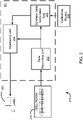
- FIG. 2 there is illustrated an example embodiment of an assembly 210, comprising an electrolyzer cell-room 200 having one or more electrolyzers, where each one of the electrolyzers is composed of a plurality of electrolysis cells connected electrically in series.
- a fault detection system 201 is operatively coupled to the electrolyzers in the cell-room 200.
- the fault detection system 201 is configured to perform real-time data recording through a data recording unit 202. Data is recorded in real-time and provided to a synthetic data generation unit 203 and a monitoring unit 204.
- the monitoring unit 204 is coupled to the synthetic data generation unit 203 to receive synthetic data.
- the monitoring unit 204 is coupled to an interface 205 for displaying results and/or detected faults/alerts.
- data recording unit 202 Although the data recording unit 202, synthetic data generation unit 203, and monitoring unit 204 are illustrated as separate components, it will be understood that this is for illustrative purposes only and that the functionalities provided by each one of these units may be represented by one or more software and/or hardware modules, depending on practical implementation.
- Data recording comprises sampling voltage measurements of the plurality of electrolysis cells during all operation modes of the electrolyzers.
- electrical current powering each electrolyzer of the cell-room 200 is recorded, and sensor data measurements are received.
- the sensor data measurements may include, but are not limited to: electrolyzer catholyte outlet temperature, caustic outlet concentration, H 2 pressure, flow of product, and product output flow of caustic produced by the plurality of electrolyzers.
- Synthetic data generation comprises calculating synthetic cell-specific voltages and synthetic product output flow of caustic, synthetic anolyte pH, feed brine pH, or oxygen in chlorine gas concentration.
- the calculations may be performed using nonlinear predictive models predefined and stored in a calibration device 206, which is illustrated as separate from the fault detection system 201 but in some embodiments may be integrated therewith, in part or in whole.
- single cell k-factors calculated by the calibration device 206 may be input to the fault detection system 201, for example through the synthetic data generation unit 206.
- a k-factor is understood as a slope of a main rectifier electrical current density versus cell electrical voltage.
- the k-factors may be calculated from data used to build the predictive models for the synthetic cell-specific voltages.
- single cell U 0 are calculated by the calibration device 206.
- the U 0 is understood as an intercept of a main rectifier electrical current density versus cell electrical voltage, it can be calculated from data used to build the predictive models for the synthetic cell-specific voltages.
- the interface 205 may be used to display alarms triggered by the fault detection system 201. Based on these alarms, a human operator can take counter measure actions to reduce the impact of the contamination, such us stopping the electrolysis process and/or fixing the filtration process to reduce the impurities levels under the recommended levels.
- the fault detection system 201 detects a slow contamination and harmful operating conditions if the difference between non synthetic and synthetic caustic product output flow exceeds a threshold. Similarly, fast contamination and harmful operating conditions are detected if the cell-specific calculated k-factor exceeds a threshold and if a conditional logic rule based on the difference between the single cell synthetic and real-time voltages is met. In some embodiments, the conditional logic rule is triggered when the difference between the synthetic cell voltages and real-time cell voltages exceeds a threshold.
- conditional logic rules are based on the difference between single cell synthetic voltage and single cell real-time voltage. It will be understood that certain modifications may be made to the example conditional logic rule above while still capturing the essence of fast contamination detection based on the difference between single cell synthetic voltage and single cell real-time voltage. For example, instead of the average of the differences, other aggregations such us the median may be used. The min-max range of the ⁇ short , ⁇ long time period may be replaced by the variance. Another alternative may be to track a smoothed segmentation of a differences trend to detect fast contamination. Segmentation may be calculated by building the derivative of the residuals at time t and ⁇ short , ⁇ long . Other variations may also be applied.
- Graph 300 of Fig. 3A illustrates a difference 302 between synthetic and non-synthetic voltages for a plurality of cells in an operating electrolyzer with an adequate control of contaminant levels.
- Graph 301 of Fig. 3B illustrates a difference 303 between synthetic and non-synthetic voltages for a plurality of cells in an operating electrolyzer where a fast contamination has occurred.
- the trend of the difference 303 is used with the conditional logic rule described above to detect fast contamination.
- a group of cells 304 may be less affected by the contamination due to a different intrinsic membrane design compared to other cells.
- Fig. 4 illustrates a non-limiting example of cell-room slow contamination detection represented by a continuous decrease of the difference between measured and synthetic caustic product output flow, synthetic anolyte pH, feed brine pH, or oxygen in chlorine gas concentration over time.
- threshold 402 When threshold 402 is reached, slow contamination is detected.
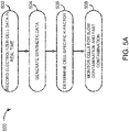
- a flowchart of an example method 500 of operating the fault detection system 201 At step 502, real-time data is recorded from the cells of the cell-room 200 during operation of the electrolyzers.
- synthetic data is generated based on historical data of the electrolyzers and the cells.
- the synthetic data comprises synthetic cell voltages and a synthetic product output flow, synthetic anolyte pH, feed brine pH, or oxygen in chlorine gas concentration of the electrolyzers, i.e. a measure of the produced caustic product output flow, anolyte pH, feed brine pH, or oxygen in chlorine gas concentration.
- cell-specific k-factors or U 0 are determined, which may comprise reading the cell-specific k-factors or U 0 from a memory or from another device, such as the calibration device 206, or calculating them from historical data of the electrolyzer.
- the k-factor or U 0 may be calculated respectively as the slope or the intercept of the linear regression of the main rectifier current density to the single cell corrected voltage, and the single cell corrected voltage is calculated by the linear standardization of the single cell voltage measurement to the electrolyzer catholyte outlet temperature and caustic concentration.
- the cells of the electrolyzers are monitored for slow contamination and fast contamination.
- Slow contamination is detected when a difference between the synthetic product output flow, synthetic anolyte pH, feed brine pH, or oxygen in chlorine gas concentration, and a real-time product output flow, anolyte pH, feed brine pH, or oxygen in chlorine gas concentration exceeds a threshold.
- slow contamination is detected when a difference between real-time product output flow and synthetic product output flow, or a difference between real-time anolyte pH and synthetic anolyte pH, or a difference between real-time feed brine pH and synthetic feed brine pH, or a difference between real-time oxygen in chlorine gas concentration and synthetic oxygen in chlorine gas concentration exceeds the threshold.
- Fast contamination is detected when the cell-specific k-factor exceeds a second threshold and a trend of a difference between the synthetic cell voltages and real-time cell voltages meets the conditional logic rule.
- the method 500 may be repeated any number of times, at random, regular, or predetermined intervals. In some embodiments, the method 500 is performed continuously until at least one fault is detected. Other embodiments may also apply.
- Slow and fast contamination detection are performed on the basis of certain models, which may be determined by the calibration device 206. These models include but are not limited to a model for synthetic voltage and a model for product output flow, anolyte pH, feed brine pH, or oxygen in chlorine gas concentration.
- Fig. 5B there is illustrated a flowchart of an example method 510 used for slow contamination detection, as performed by the calibration device 206 or the fault detection system 201. Step 512 initiates the process of building the caustic product output flow predictive model. The calibration may be triggered, for example, if the system is newly deployed in an industrial production site, or if the accuracy of existing predictive models is lower than a threshold.
- the accuracy of the predictive model is calculated by subtracting the real-time recorded caustic product output flow, anolyte pH, feed brine pH, or oxygen in chlorine gas concentration from the synthetic caustic product output flow, synthetic anolyte pH, feed brine pH, or oxygen in chlorine gas concentration.
- step 514 recently recorded historical data representing non faulty cell-room operation at a stable current load is selected.
- the duration of selected data ranges from 10 to 30 days of operation.
- Selected process data includes but is not limited to: electrolyzers main current rectifier, electrolyzers catholyte outlet temperature, caustic outlet concentration, H 2 pressure, flow of product, and product output flow.
- the synthetic product output flow mathematical function composed of estimated parameters is calculated.
- g is non-linear function
- I is the main rectifier electrical current for each of the electrolyzers in the selected data
- T is catholyte outlet temperature for each of the electrolyzers in the selected data
- NE is the number of electrolyzers
- P H 2 is measured hydrogen pressure in the selected data
- d is a backward time delay.
- the flow of product measured by a product output flow meter is used.
- parameters of function g are estimated using a neuralnetwork model.
- parameters of the function g are estimated using Kalman switching filters or non-linear multivariate regression techniques. The estimated parameters of the function g are stored at step 518.
- Step 522 executes the data selection process for building the synthetic single cell voltage nonlinear predictive model.
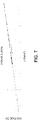
- Fig. 6 depicts a non-limiting example of operation data selected by step 522.
- relevant data for building single cell voltage predictive models is continuously selected during the sequence of electrical current ramp up and stabilization at maximum load during a given time frame, such as 72 hours.
- step 524 single cell synthetic mathematical functions composed of various estimated parameters are executed. Some of these parameters are operation specific, identical for all the cells that perform the electrolysis for the same operating conditions. Some of the parameters are cell-specific parameters.
- v ⁇ volts f I t ⁇ d ... t , T t ⁇ d ... t , CC t ⁇ d ... t
- parameters of function ⁇ are estimated using a neuralnetwork model based on an encoder-decoder, where the decoder is replaced with a predictor - a subnetwork that predicts the cell's voltage.
- a neural encoder is a type of neural architecture whose objective is to take an input vector and reduce its dimensionality to a desired one. It may be paired with a decoder. The decoder receives the output of the encoder and transforms it to minimize an objective function.
- the neural encoder may be used to find features that represent the specificity of the cells at operation cycles and thus the normal degradation.
- the predictor may consider temporal delays of the measurements. The predictor does not use the measured voltage as an input, yet it is still able to predict a different voltage for each cell, despite using the same operating conditions as input. It accomplishes this by taking the output of the encoder as an input, which is unique for each cell. Hence, the voltage prediction is not biased by the cell's measured voltage.
- parameters of the function ⁇ are estimated using Kalman switching filters or non-linear multivariate regression techniques.
- Step 526 stores estimated parameters of the function ⁇ .
- the k-factor is the slope of the linear regression applied on selected data samples from step 522.
- the linear regression is executed on selected single cell voltages corrected to electrolyzer outlet catholyte temperature (C°), caustic outlet concentration (% w/w) and the electrolyzer current density (electrical current divided by cell area) at step 524.
- C° electrolyzer outlet catholyte temperature
- % w/w caustic outlet concentration
- electrolyzer current density electric current divided by cell area
- v is the single cell voltage (volts) from a selected time period
- ref temp is the outlet catholyte temperature operation reference constant in degrees Celsius
- CT is the outlet catholyte temperature operation correction constant
- Temp is the measured catholyte temperature during selected data
- ref conc is the caustic outlet concentration operation reference constant in % w/w
- CC is the caustic outlet concentration correction constant
- Conc is the measured caustic concentration during selected data
- / is the current density in Kilo Amperes per square meters calculated by dividing the electric current by the cell Area.
- methods 510, 520 may, in some embodiments, be performed, in whole or in part, by the fault detection system 201, for example by the synthetic data generation unit 203.
- the calibration device 206 provides the models on which the synthetic data are based and the calculations are performed by the synthetic data generation unit.
- the fault detection method is implemented as follows.
- the calibration device 206 selects historical data to build a predictive model for the synthetic voltage, selects historical data to build a predictive model for the product output flow, anolyte pH, feed brine pH, or oxygen in chlorine gas concentration, builds the predictive model for the synthetic voltage, and calculates k-factors or U 0 from the historical data for building the model for the synthetic voltage.
- the synthetic unit 203 calculates synthetic voltages using the predictive model for the synthetic voltage and calculates the synthetic product output flow using the predictive model for the synthetic product output flow.
- the monitoring unit 204 executes the conditional logic rule for the trends on the differences between the synthetic and real time voltages, calculates the differences between the synthetic and real time product output flow, anolyte pH, feed brine pH, or oxygen in chlorine gas concentration, and monitors the k-factors.
- the monitoring unit 204 issues an alert when the conditional logic rule is met and/or the product output flow difference crosses a threshold and/or the range of k-factors or U 0 exceed a threshold for all cells.
- Fig. 8 is an example embodiment of a computing device 800 for implementing one or more of the methods 500, 510, 520 for detecting contamination in a cell of an electrolyzer having a plurality of cells.
- the fault detection system and/or the calibration device 206 is implemented using one or more computing device 800.
- the computing device 800 comprises a processing unit 801 and a memory 803 which has stored therein computer-executable instructions 802.
- the processing unit 801 may comprise any suitable devices configured to cause a series of steps to be performed such that instructions 802, when executed by the computing device 800 or other programmable apparatus, may cause the functions/acts/steps specified in the methods 500, 510, 520 described herein to be executed.
- the processing unit 801 may comprise, for example, any type of general-purpose microprocessor or microcontroller, a digital signal processing (DSP) processor, a CPU, an integrated circuit, a field programmable gate array (FPGA), a reconfigurable processor, other suitably programmed or programmable logic circuits, or any combination thereof.
- DSP digital signal processing
- FPGA field programmable gate array
- reconfigurable processor other suitably programmed or programmable logic circuits, or any combination thereof.
- the memory 803 may comprise any suitable known or other machine-readable storage medium.
- the memory 803 may comprise a non-transitory computer readable storage medium, for example, but not limited to, an electronic, magnetic, optical, electromagnetic, infrared, or semiconductor system, apparatus, or device, or any suitable combination of the foregoing.
- the memory 803 may include a suitable combination of any type of computer memory that is located either internally or externally to device, for example random-access memory (RAM), read-only memory (ROM), electro-optical memory, magneto-optical memory, erasable programmable read-only memory (EPROM), and electrically erasable programmable read-only memory (EEPROM), Ferroelectric RAM (FRAM) or the like.
- Memory 803 may comprise any storage means (e.g., devices) suitable for retrievably storing machine-readable instructions 802 executable by processing unit 801.
- the methods and systems for detecting contamination in a cell of an electrolyzer having a plurality of cells as described herein may be implemented in a high level procedural or object oriented programming or scripting language, or a combination thereof, to communicate with or assist in the operation of a computer system, for example the computing device 800.
- the methods and systems for detecting contamination in a cell of an electrolyzer having a plurality of cells may be implemented in assembly or machine language.
- the language may be a compiled or interpreted language.
- Program code for implementing the methods and systems for detecting a fault in an electrolyzer may be stored on a storage media or a device, for example a ROM, a magnetic disk, an optical disc, a flash drive, or any other suitable storage media or device.
- the program code may be readable by a general or special-purpose programmable computer for configuring and operating the computer when the storage media or device is read by the computer to perform the procedures described herein.
- Embodiments of the methods and systems for detecting contamination in a cell of an electrolyzer having a plurality of cells may also be considered to be implemented by way of a non-transitory computer-readable storage medium having a computer program stored thereon.
- the computer program may comprise computer-readable instructions which cause a computer, or more specifically the processing unit 801 of the computing device 800, to operate in a specific and predefined manner to perform the functions described herein.
- Computer-executable instructions may be in many forms, including program modules, executed by one or more computers or other devices.
- program modules include routines, programs, objects, components, data structures, etc., that perform tasks or implement particular abstract data types.
- functionality of the program modules may be combined or distributed as desired in various embodiments.
Landscapes
- Engineering & Computer Science (AREA)
- Chemical & Material Sciences (AREA)
- Physics & Mathematics (AREA)
- Materials Engineering (AREA)
- Electrochemistry (AREA)
- Chemical Kinetics & Catalysis (AREA)
- Organic Chemistry (AREA)
- Metallurgy (AREA)
- Automation & Control Theory (AREA)
- Theoretical Computer Science (AREA)
- General Physics & Mathematics (AREA)
- Analytical Chemistry (AREA)
- Evolutionary Computation (AREA)
- Artificial Intelligence (AREA)
- Mathematical Physics (AREA)
- General Engineering & Computer Science (AREA)
- Software Systems (AREA)
- Data Mining & Analysis (AREA)
- Computing Systems (AREA)
- Health & Medical Sciences (AREA)
- Life Sciences & Earth Sciences (AREA)
- Biomedical Technology (AREA)
- Biophysics (AREA)
- Computational Linguistics (AREA)
- Inorganic Chemistry (AREA)
- General Health & Medical Sciences (AREA)
- Molecular Biology (AREA)
- Geometry (AREA)
- Computer Hardware Design (AREA)
- Medical Informatics (AREA)
- Computer Vision & Pattern Recognition (AREA)
- Electrolytic Production Of Non-Metals, Compounds, Apparatuses Therefor (AREA)
- Water Treatment By Electricity Or Magnetism (AREA)
Applications Claiming Priority (1)
| Application Number | Priority Date | Filing Date | Title |
|---|---|---|---|
| US202063119097P | 2020-11-30 | 2020-11-30 |
Publications (3)
| Publication Number | Publication Date |
|---|---|
| EP4008806A1 true EP4008806A1 (fr) | 2022-06-08 |
| EP4008806B1 EP4008806B1 (fr) | 2025-01-01 |
| EP4008806C0 EP4008806C0 (fr) | 2025-01-01 |
Family
ID=78806430
Family Applications (1)
| Application Number | Title | Priority Date | Filing Date |
|---|---|---|---|
| EP21210902.9A Active EP4008806B1 (fr) | 2020-11-30 | 2021-11-26 | Procédés et systèmes de détection de contamination dans des cellules d'électrolyse |
Country Status (7)
| Country | Link |
|---|---|
| US (1) | US12366000B2 (fr) |
| EP (1) | EP4008806B1 (fr) |
| JP (1) | JP7474233B2 (fr) |
| CN (1) | CN114574878A (fr) |
| CA (1) | CA3140533A1 (fr) |
| ES (1) | ES3014389T3 (fr) |
| PL (1) | PL4008806T3 (fr) |
Cited By (2)
| Publication number | Priority date | Publication date | Assignee | Title |
|---|---|---|---|---|
| EP4497849A4 (fr) * | 2022-03-23 | 2025-07-30 | Asahi Chemical Ind | Procédé d'aide au fonctionnement, dispositif d'aide au fonctionnement, système d'aide au fonctionnement et programme d'aide au fonctionnement |
| EP4717796A3 (fr) * | 2024-09-26 | 2026-04-08 | Honeywell International Inc. | Procédés, appareils et produits-programmes informatiques pour diagnostiquer une condition de dégradation dans un électrolyseur |
Families Citing this family (6)
| Publication number | Priority date | Publication date | Assignee | Title |
|---|---|---|---|---|
| EP4372127A4 (fr) * | 2021-07-16 | 2025-06-25 | Asahi Kasei Kabushiki Kaisha | Système d'analyse, procédé d'analyse et programme d'analyse |
| JP7202501B1 (ja) | 2022-09-29 | 2023-01-11 | 旭化成株式会社 | 運転支援装置、運転支援方法および運転支援プログラム |
| AU2023300838A1 (en) * | 2022-06-30 | 2025-01-09 | Asahi Kasei Kabushiki Kaisha | Device and method |
| CN116840310A (zh) * | 2023-05-31 | 2023-10-03 | 蓝星(北京)化工机械有限公司 | 一种检测设备 |
| CN118007188B (zh) * | 2024-02-19 | 2024-08-20 | 太和气体(荆州)有限公司 | 一种基于数据处理的氯气生产自运安全监测系统 |
| CN120366809B (zh) * | 2025-06-27 | 2025-11-11 | 福建浩达智能科技股份有限公司 | 一种节电电解海水制备次氯酸钠的装置和系统 |
Citations (4)
| Publication number | Priority date | Publication date | Assignee | Title |
|---|---|---|---|---|
| EP0136806A2 (fr) * | 1983-09-06 | 1985-04-10 | Olin Corporation | Système de contrôle de cellule chlore-alcali basé sur l'analyse du flux de matière |
| US20070208519A1 (en) * | 2006-02-03 | 2007-09-06 | Michel Veillette | Adaptive method and system of monitoring signals for detecting anomalies |
| EP2226411A1 (fr) * | 2009-03-06 | 2010-09-08 | Recherche 2000 Inc. | Procédé pour garantir et surveiller la sécurité et les performances d'un électrolyseur |
| US20150021193A1 (en) * | 2013-07-17 | 2015-01-22 | Bayer Materialscience Ag | Method and system for monitoring the functionality of electrolysis cells |
Family Cites Families (6)
| Publication number | Priority date | Publication date | Assignee | Title |
|---|---|---|---|---|
| EP1910588B1 (fr) * | 2005-06-16 | 2018-05-16 | Recherche 2000 Inc. | Procédé et système de diagnostic d'un électrolyseur se basant sur un ajustement analytique de courbe et une optimisation d'efficacite |
| US8152987B2 (en) * | 2010-04-02 | 2012-04-10 | Recherche 2000 Inc. | Method for ensuring and monitoring electrolyzer safety and performances |
| JP5770829B2 (ja) | 2010-04-23 | 2015-08-26 | ルシェルシュ 2000 インコーポレイテッド | 電解装置の安全性及び性能を確保し監視する方法 |
| DE102011107935A1 (de) | 2011-07-19 | 2013-01-24 | Thyssenkrupp Uhde Gmbh | Verfahren zur Bestimmung eines sicheren und wirtschaftlichen stromdichteabhängigen Spannungs- und/oder spezifischen Energieverbrauchsbetriebsbereichs |
| CN111491094B (zh) | 2019-01-28 | 2021-08-31 | 北京小米移动软件有限公司 | 摄像模组及终端 |
| EP3851560A1 (fr) * | 2020-01-16 | 2021-07-21 | Recherche 2000 Inc. | Procédés et systèmes pour détecter des défauts dans des électrolyseurs ayant des cellules d'électrolyse |
-
2021
- 2021-11-26 PL PL21210902.9T patent/PL4008806T3/pl unknown
- 2021-11-26 ES ES21210902T patent/ES3014389T3/es active Active
- 2021-11-26 CA CA3140533A patent/CA3140533A1/fr active Pending
- 2021-11-26 EP EP21210902.9A patent/EP4008806B1/fr active Active
- 2021-11-29 US US17/536,166 patent/US12366000B2/en active Active
- 2021-11-30 CN CN202111446970.0A patent/CN114574878A/zh active Pending
- 2021-11-30 JP JP2021194115A patent/JP7474233B2/ja active Active
Patent Citations (4)
| Publication number | Priority date | Publication date | Assignee | Title |
|---|---|---|---|---|
| EP0136806A2 (fr) * | 1983-09-06 | 1985-04-10 | Olin Corporation | Système de contrôle de cellule chlore-alcali basé sur l'analyse du flux de matière |
| US20070208519A1 (en) * | 2006-02-03 | 2007-09-06 | Michel Veillette | Adaptive method and system of monitoring signals for detecting anomalies |
| EP2226411A1 (fr) * | 2009-03-06 | 2010-09-08 | Recherche 2000 Inc. | Procédé pour garantir et surveiller la sécurité et les performances d'un électrolyseur |
| US20150021193A1 (en) * | 2013-07-17 | 2015-01-22 | Bayer Materialscience Ag | Method and system for monitoring the functionality of electrolysis cells |
Non-Patent Citations (1)
| Title |
|---|
| BATISTA LUANA ET AL: "A Multi-Expert System for chlorine electrolyzer monitoring", EXPERT SYSTEMS WITH APPLICATIONS, ELSEVIER, AMSTERDAM, NL, vol. 40, no. 8, 2 January 2013 (2013-01-02), pages 3128 - 3136, XP028982539, ISSN: 0957-4174, DOI: 10.1016/J.ESWA.2012.12.094 * |
Cited By (2)
| Publication number | Priority date | Publication date | Assignee | Title |
|---|---|---|---|---|
| EP4497849A4 (fr) * | 2022-03-23 | 2025-07-30 | Asahi Chemical Ind | Procédé d'aide au fonctionnement, dispositif d'aide au fonctionnement, système d'aide au fonctionnement et programme d'aide au fonctionnement |
| EP4717796A3 (fr) * | 2024-09-26 | 2026-04-08 | Honeywell International Inc. | Procédés, appareils et produits-programmes informatiques pour diagnostiquer une condition de dégradation dans un électrolyseur |
Also Published As
| Publication number | Publication date |
|---|---|
| US20220170170A1 (en) | 2022-06-02 |
| ES3014389T3 (en) | 2025-04-22 |
| US12366000B2 (en) | 2025-07-22 |
| JP7474233B2 (ja) | 2024-04-24 |
| JP2022087079A (ja) | 2022-06-09 |
| EP4008806B1 (fr) | 2025-01-01 |
| CN114574878A (zh) | 2022-06-03 |
| CA3140533A1 (fr) | 2022-05-30 |
| EP4008806C0 (fr) | 2025-01-01 |
| PL4008806T3 (pl) | 2025-04-22 |
Similar Documents
| Publication | Publication Date | Title |
|---|---|---|
| EP4008806B1 (fr) | Procédés et systèmes de détection de contamination dans des cellules d'électrolyse | |
| US12195863B2 (en) | Methods and systems for detecting faults in electrolysers having electrolysis cells | |
| EP2006418B1 (fr) | Optimisation de l'efficacité et détection des dommages de cellules d'électrolyse | |
| EP1979715B1 (fr) | Procédé et système adaptatif de contrôle de signaux pour détecter des anomalies | |
| EP1910588B1 (fr) | Procédé et système de diagnostic d'un électrolyseur se basant sur un ajustement analytique de courbe et une optimisation d'efficacite | |
| US8152987B2 (en) | Method for ensuring and monitoring electrolyzer safety and performances | |
| EP2226411B1 (fr) | Procédé pour garantir et surveiller la sécurité et les performances d'un électrolyseur | |
| US20150021193A1 (en) | Method and system for monitoring the functionality of electrolysis cells | |
| EP2419550B1 (fr) | Procédé et système pour déterminer le rendement de courant d'une unique cellule dans un électrolyseur | |
| CA2794737C (fr) | Procede pour garantir et surveiller la securite et les performances d'un electrolyseur | |
| EP2853888A2 (fr) | Procédé de mesure de chlorure et pH. | |
| HK40053623A (en) | Methods and systems for detecting faults in electrolysers having electrolysis cells | |
| HK40053623B (zh) | 检测具有电解电池的电解装置中的故障的方法和系统 |
Legal Events
| Date | Code | Title | Description |
|---|---|---|---|
| PUAI | Public reference made under article 153(3) epc to a published international application that has entered the european phase |
Free format text: ORIGINAL CODE: 0009012 |
|
| STAA | Information on the status of an ep patent application or granted ep patent |
Free format text: STATUS: REQUEST FOR EXAMINATION WAS MADE |
|
| 17P | Request for examination filed |
Effective date: 20211126 |
|
| AK | Designated contracting states |
Kind code of ref document: A1 Designated state(s): AL AT BE BG CH CY CZ DE DK EE ES FI FR GB GR HR HU IE IS IT LI LT LU LV MC MK MT NL NO PL PT RO RS SE SI SK SM TR |
|
| GRAJ | Information related to disapproval of communication of intention to grant by the applicant or resumption of examination proceedings by the epo deleted |
Free format text: ORIGINAL CODE: EPIDOSDIGR1 |
|
| STAA | Information on the status of an ep patent application or granted ep patent |
Free format text: STATUS: GRANT OF PATENT IS INTENDED |
|
| GRAP | Despatch of communication of intention to grant a patent |
Free format text: ORIGINAL CODE: EPIDOSNIGR1 |
|
| RIC1 | Information provided on ipc code assigned before grant |
Ipc: G05B 23/02 20060101ALI20240607BHEP Ipc: C25B 1/46 20060101ALI20240607BHEP Ipc: C25B 15/031 20210101ALI20240607BHEP Ipc: C25B 15/023 20210101ALI20240607BHEP Ipc: C25B 9/70 20210101AFI20240607BHEP |
|
| INTG | Intention to grant announced |
Effective date: 20240701 |
|
| RIN1 | Information on inventor provided before grant (corrected) |
Inventor name: TREMBLAY, GILLES J. Inventor name: LADEMANN, HELMUT Inventor name: BERRIAH, SAID |
|
| GRAS | Grant fee paid |
Free format text: ORIGINAL CODE: EPIDOSNIGR3 |
|
| GRAA | (expected) grant |
Free format text: ORIGINAL CODE: 0009210 |
|
| STAA | Information on the status of an ep patent application or granted ep patent |
Free format text: STATUS: THE PATENT HAS BEEN GRANTED |
|
| AK | Designated contracting states |
Kind code of ref document: B1 Designated state(s): AL AT BE BG CH CY CZ DE DK EE ES FI FR GB GR HR HU IE IS IT LI LT LU LV MC MK MT NL NO PL PT RO RS SE SI SK SM TR |
|
| REG | Reference to a national code |
Ref country code: GB Ref legal event code: FG4D |
|
| REG | Reference to a national code |
Ref country code: DE Ref legal event code: R096 Ref document number: 602021024210 Country of ref document: DE |
|
| REG | Reference to a national code |
Ref country code: CH Ref legal event code: EP |
|
| REG | Reference to a national code |
Ref country code: IE Ref legal event code: FG4D |
|
| U01 | Request for unitary effect filed |
Effective date: 20250203 |
|
| U07 | Unitary effect registered |
Designated state(s): AT BE BG DE DK EE FI FR IT LT LU LV MT NL PT RO SE SI Effective date: 20250207 |
|
| REG | Reference to a national code |
Ref country code: ES Ref legal event code: FG2A Ref document number: 3014389 Country of ref document: ES Kind code of ref document: T3 Effective date: 20250422 |
|
| PG25 | Lapsed in a contracting state [announced via postgrant information from national office to epo] |
Ref country code: IS Free format text: LAPSE BECAUSE OF FAILURE TO SUBMIT A TRANSLATION OF THE DESCRIPTION OR TO PAY THE FEE WITHIN THE PRESCRIBED TIME-LIMIT Effective date: 20250501 |
|
| PG25 | Lapsed in a contracting state [announced via postgrant information from national office to epo] |
Ref country code: HR Free format text: LAPSE BECAUSE OF FAILURE TO SUBMIT A TRANSLATION OF THE DESCRIPTION OR TO PAY THE FEE WITHIN THE PRESCRIBED TIME-LIMIT Effective date: 20250101 |
|
| PG25 | Lapsed in a contracting state [announced via postgrant information from national office to epo] |
Ref country code: GR Free format text: LAPSE BECAUSE OF FAILURE TO SUBMIT A TRANSLATION OF THE DESCRIPTION OR TO PAY THE FEE WITHIN THE PRESCRIBED TIME-LIMIT Effective date: 20250402 |
|
| PG25 | Lapsed in a contracting state [announced via postgrant information from national office to epo] |
Ref country code: CZ Free format text: LAPSE BECAUSE OF FAILURE TO SUBMIT A TRANSLATION OF THE DESCRIPTION OR TO PAY THE FEE WITHIN THE PRESCRIBED TIME-LIMIT Effective date: 20250101 |
|
| PG25 | Lapsed in a contracting state [announced via postgrant information from national office to epo] |
Ref country code: SM Free format text: LAPSE BECAUSE OF FAILURE TO SUBMIT A TRANSLATION OF THE DESCRIPTION OR TO PAY THE FEE WITHIN THE PRESCRIBED TIME-LIMIT Effective date: 20250101 |
|
| PG25 | Lapsed in a contracting state [announced via postgrant information from national office to epo] |
Ref country code: SK Free format text: LAPSE BECAUSE OF FAILURE TO SUBMIT A TRANSLATION OF THE DESCRIPTION OR TO PAY THE FEE WITHIN THE PRESCRIBED TIME-LIMIT Effective date: 20250101 |
|
| PLBE | No opposition filed within time limit |
Free format text: ORIGINAL CODE: 0009261 |
|
| STAA | Information on the status of an ep patent application or granted ep patent |
Free format text: STATUS: NO OPPOSITION FILED WITHIN TIME LIMIT |
|
| REG | Reference to a national code |
Ref country code: CH Ref legal event code: L10 Free format text: ST27 STATUS EVENT CODE: U-0-0-L10-L00 (AS PROVIDED BY THE NATIONAL OFFICE) Effective date: 20251112 |
|
| REG | Reference to a national code |
Ref country code: CH Ref legal event code: U11 Free format text: ST27 STATUS EVENT CODE: U-0-0-U10-U11 (AS PROVIDED BY THE NATIONAL OFFICE) Effective date: 20251201 |
|
| 26N | No opposition filed |
Effective date: 20251002 |
|
| U20 | Renewal fee for the european patent with unitary effect paid |
Year of fee payment: 5 Effective date: 20251118 |
|
| PGFP | Annual fee paid to national office [announced via postgrant information from national office to epo] |
Ref country code: GB Payment date: 20251113 Year of fee payment: 5 |
|
| PGFP | Annual fee paid to national office [announced via postgrant information from national office to epo] |
Ref country code: NO Payment date: 20251126 Year of fee payment: 5 |
|
| PGFP | Annual fee paid to national office [announced via postgrant information from national office to epo] |
Ref country code: CH Payment date: 20251201 Year of fee payment: 5 |
|
| PGFP | Annual fee paid to national office [announced via postgrant information from national office to epo] |
Ref country code: IE Payment date: 20251126 Year of fee payment: 5 |
|
| PGFP | Annual fee paid to national office [announced via postgrant information from national office to epo] |
Ref country code: PL Payment date: 20251114 Year of fee payment: 5 |
|
| PGFP | Annual fee paid to national office [announced via postgrant information from national office to epo] |
Ref country code: ES Payment date: 20251212 Year of fee payment: 5 |