EP4008807B1 - Verfahren zur überwachung der impedanz eines elektrolyseurs, steuergerät und stromversorgung - Google Patents
Verfahren zur überwachung der impedanz eines elektrolyseurs, steuergerät und stromversorgung Download PDFInfo
- Publication number
- EP4008807B1 EP4008807B1 EP21179371.6A EP21179371A EP4008807B1 EP 4008807 B1 EP4008807 B1 EP 4008807B1 EP 21179371 A EP21179371 A EP 21179371A EP 4008807 B1 EP4008807 B1 EP 4008807B1
- Authority
- EP
- European Patent Office
- Prior art keywords
- power supply
- electric energy
- electrolyzer
- signal
- impedance
- Prior art date
- Legal status (The legal status is an assumption and is not a legal conclusion. Google has not performed a legal analysis and makes no representation as to the accuracy of the status listed.)
- Active
Links
Images

Classifications
-
- C—CHEMISTRY; METALLURGY
- C25—ELECTROLYTIC OR ELECTROPHORETIC PROCESSES; APPARATUS THEREFOR
- C25B—ELECTROLYTIC OR ELECTROPHORETIC PROCESSES FOR THE PRODUCTION OF COMPOUNDS OR NON-METALS; APPARATUS THEREFOR
- C25B15/00—Operating or servicing cells
- C25B15/02—Process control or regulation
- C25B15/023—Measuring, analysing or testing during electrolytic production
-
- G—PHYSICS
- G01—MEASURING; TESTING
- G01R—MEASURING ELECTRIC VARIABLES; MEASURING MAGNETIC VARIABLES
- G01R27/00—Arrangements for measuring resistance, reactance, impedance, or electric characteristics derived therefrom
- G01R27/02—Measuring real or complex resistance, reactance, impedance, or other two-pole characteristics derived therefrom, e.g. time constant
- G01R27/08—Measuring resistance by measuring both voltage and current
-
- C—CHEMISTRY; METALLURGY
- C25—ELECTROLYTIC OR ELECTROPHORETIC PROCESSES; APPARATUS THEREFOR
- C25B—ELECTROLYTIC OR ELECTROPHORETIC PROCESSES FOR THE PRODUCTION OF COMPOUNDS OR NON-METALS; APPARATUS THEREFOR
- C25B15/00—Operating or servicing cells
- C25B15/02—Process control or regulation
-
- G—PHYSICS
- G01—MEASURING; TESTING
- G01R—MEASURING ELECTRIC VARIABLES; MEASURING MAGNETIC VARIABLES
- G01R19/00—Arrangements for measuring currents or voltages or for indicating presence or sign thereof
-
- G—PHYSICS
- G01—MEASURING; TESTING
- G01R—MEASURING ELECTRIC VARIABLES; MEASURING MAGNETIC VARIABLES
- G01R27/00—Arrangements for measuring resistance, reactance, impedance, or electric characteristics derived therefrom
- G01R27/02—Measuring real or complex resistance, reactance, impedance, or other two-pole characteristics derived therefrom, e.g. time constant
- G01R27/16—Measuring impedance of element or network through which a current is passing from another source, e.g. cable, power line
-
- G—PHYSICS
- G05—CONTROLLING; REGULATING
- G05B—CONTROL OR REGULATING SYSTEMS IN GENERAL; FUNCTIONAL ELEMENTS OF SUCH SYSTEMS; MONITORING OR TESTING ARRANGEMENTS FOR SUCH SYSTEMS OR ELEMENTS
- G05B19/00—Program-control systems
- G05B19/02—Program-control systems electric
- G05B19/04—Program control other than numerical control, i.e. in sequence controllers or logic controllers
- G05B19/042—Program control other than numerical control, i.e. in sequence controllers or logic controllers using digital processors
-
- C—CHEMISTRY; METALLURGY
- C25—ELECTROLYTIC OR ELECTROPHORETIC PROCESSES; APPARATUS THEREFOR
- C25B—ELECTROLYTIC OR ELECTROPHORETIC PROCESSES FOR THE PRODUCTION OF COMPOUNDS OR NON-METALS; APPARATUS THEREFOR
- C25B1/00—Electrolytic production of inorganic compounds or non-metals
- C25B1/01—Products
- C25B1/02—Hydrogen or oxygen
Definitions
- the present disclosure relates to the technical field of testing, and in particular to a method for monitoring impedance of an electrolyzer, a controller and a power supply.
- An electrolyzer is a core device for converting electric energy into hydrogen energy. Impedance of the electrolyzer can indicate service life of the electrolyzer to some extent. Generally, the impedance of the electrolyzer increases with the decrease (such as decrease of catalyst activity, coating shedding) of the service life of the electrolyzer. Therefore, it is important to monitor the impedance of the electrolyzer, for maintenance of the electrolyzer.
- WO2021/162553 provides an alternating current (AC) to direct current (DC) converting circuit for a turbine generator, which comprises an active AC/DC converter having an input for receiving alternating current electrical power from a turbine generator and an output for providing direct current electrical power to an electrolysis system for electrolysis of water.
- AC alternating current
- DC direct current
- the AC/DC converter further comprises an oscillator for generating an alternating current auxiliary signal and a summation circuit for adding the alternating current signal to the output of the active AC/DC converter.
- an oscillator for generating an alternating current auxiliary signal
- a summation circuit for adding the alternating current signal to the output of the active AC/DC converter.
- a weak alternating current (if) of frequency (f) is superimposed upon the electrolysis current, the active part (rf) of the impedance which the cell offers to this alternating current is measured, followed by extrapolation to the zero frequency of the function giving the active part (rf) of the impedance as a function of the frequency (f), (rf) thus inclining towards the internal resistance of the cell.
- the invention is applicable to any electrolysis cell and more particularly to cells for the igneous electrolysis of alumina.
- FIG. 1 An equivalent model of the electrolyzer is shown in Figure 1 .
- the impedance of the electrolyzer has a resistive-capacitive characteristic, mainly including a resistive component.
- Figure 2 is a schematic diagram of an impedance spectroscopy curve of the electrolyzer, in which a horizontal axis represents a real part of an impedance value and a vertical axis represents an imaginary part of the impedance value.
- a complete impedance curve can be acquired by acquiring impedance values corresponding to different frequency scanning points are acquired through an impedance scanning signal.
- the operation state and service life of the electrolyzer can be determined from the monitored impedance of the electrolyzer.
- the impedance of the electrolyzer increases with the decrease of the service life of the electrolyzer.
- impedance of a newly produced electrolyzer is shown as the curve 1, then the impedance is changed to the curve 2 after the electrolyzer is used for a time period (for example, 7800 hours), and then the impedance is changed to the curve 3 after the electrolyzer is repaired and maintained.
- the overall impedance curve of the electrolyzer moves to the right of the curve 1 after the electrolyzer is used for a time period, indicating increased impedance.
- the impedance curve substantially coincides with the curve 1 of the impedance of the original electrolyzer, indicating that the impedance returns to the original state.
- a starting point on the left side of the curve indicates the resistive impedance of the electrolyzer.
- a diameter of a curve segment on the right side of the curve indicates the performance of an anode catalyst, and a diameter of a curve segment on the left side of the curve indicates the performance of a cathode catalyst.
- a small diameter indicates a good performance of the catalyst. Therefore, based on the above theory, the impedance, the service life and the maintenance situation of the electrolyzer can be acquired by analyzing the impedance curve.
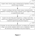
- Figure 3 is a flow chart of a method for monitoring impedance of an electrolyzer according to an embodiment of the present disclosure. The method is applied to a power supply system of an electrolyzer.
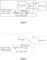
- a power supply system 1 of an electrolyzer includes a power supply 11 and a controller 12.
- the power supply 11 provides electric energy for an electrolyzer 2.
- the controller 12 controls an electric signal outputted by the power supply 11.
- An output end of the power supply 11 is connected with a voltage sensor V and a current sensor A.
- the output end of the power supply 11 may be connected in parallel with the voltage sensor V to form a parallel branch and then the parallel branch is connected in series with the current sensor A.
- the output end of the power supply 11 may be connected in series with the current sensor A to form a series branch and then the series branch is connected in parallel with the voltage sensor V.
- the method for monitoring impedance of an electrolyzer is described with reference to Figure 3 below.
- the method is applied to the controller 12. As shown in Figure 3 , the method includes the following steps S110 to S140.
- step S110 a basic electric energy command and an impedance scanning electric energy command are acquired.
- the basic electric energy command and the impedance scanning electric energy command may be generated by the controller 12, or may be received from outside.
- both the basic electric energy command and the impedance scanning electric energy command are voltage commands.
- the basic electric energy command is used to control the power supply to output a DC voltage signal corresponding to the basic electric energy command.
- the impedance scanning electric energy command is used to control the power supply to output an AC voltage signal corresponding to the impedance scanning electric energy command.
- the method of voltage control is commonly used in the initial commissioning of the electrolyzer to test whether a basic function of the electrolyzer is normal.
- both the basic electric energy command and the impedance scanning electric energy command are current commands.
- the basic electric energy command is used to control the power supply to output a DC current signal corresponding to the basic electric energy command.
- the impedance scanning electric energy command is used to control the power supply to output an AC current signal corresponding to the impedance scanning electric energy command.
- the method of current control is commonly used in the normal operation of the electrolyzer.
- the reason is that a functional relationship exists between a current and gas amount of hydrogen/oxygen produced by the electrolyzer, so that the amount of produced gas can be calculated according to the current value.
- the current command can be changed according to a gas production demand, to regulate the actual gas production.
- the basic electric energy command and the impedance scanning electric energy command are used to control an output power of the power supply.
- the output power is controlled by controlling an output current and/or an output voltage of the power supply.
- step S120 the power supply is controlled to output an expected electric signal according to the basic electric energy command and the impedance scanning electric energy command.
- the expected electric signal includes a DC component signal and AC component signals.
- the DC component signal is used for normal operation of the electrolyzer.
- Frequencies of the AC component signals are preset frequencies in the impedance scanning electric energy command.
- the preset frequencies may include multiple different frequencies.
- step S 130 for each of the preset frequencies, a voltage vector and a current vector outputted by the power supply when outputting the DC component signal and an AC component signal having the preset frequency are acquired.
- the voltage sensor acquires, for each of the preset frequencies, a voltage vector outputted by the power supply 11 when outputting the AC component signal having the preset frequency and transmits the voltage vector to the controller 12.
- the current sensor acquires, for each of the preset frequencies, a current vector outputted by the power supply 11 when outputting the AC component signal having the preset frequency, and transmits the current sensor to the controller 12.
- step S 140 for at least one of the preset frequencies, an impedance value of the electrolyzer corresponding to the preset frequency is calculated according to the outputted voltage vector and the outputted current vector.
- the voltage vector includes a voltage amplitude and a voltage phase.
- the current vector includes a current amplitude and a current phase.
- the impedance value of the electrolyzer is calculated according to the voltage amplitude, the current amplitude and a difference between the voltage phase and the current phase.
- the electrolyzer can be equivalent to a model having resistive-capacitive impedance, mainly including resistive impedance.
- the operating power for the electrolyzer is DC power. Therefore, the electrolyzer under the normal operation condition is considered as a resistor.
- the resistance of the resistor is mainly related to a temperature of the electrolyzer and a current flowing through the electrolyzer. Heat capacity of water and heat capacity of a metal structure of the electrolyzer are two main parts of the heat capacity of the electrolyzer, which are both high so that the temperature changes slowly. Therefore, the temperature is approximately regarded as unchanged in seconds. Therefore, the impedance curve of the electrolyzer can be acquired by regulating the impedance scanning electric energy command, or regulating the impedance scanning electric energy command and the basic electric energy command.
- an AC component signal is added to an electric signal inputted into the electrolyzer, to acquire an impedance value of the electrolyzer.
- a power supply connected with the electrolyzer is controlled to output a DC component signal for the normal operation of the electrolyzer, and according to an impedance scanning electric energy command, the power supply is controlled to output AC component signals used to monitor the impedance of the electrolyzer.
- a voltage vector and a current vector outputted by the power supply are acquired, and the impedance value of the electrolyzer is calculated according to the voltage vector and the current vector.
- the impedance scanning can be performed in a real-time manner during the normal operation of the electrolyzer, to calculate the impedance value of the electrolyzer, so as to evaluate the operation state and the service life of the electrolyzer.
- the above process according to the present disclosure only requires hardware devices of the power supply without extra hardware devices, so that the hardware cost is reduced, and the safety of the process for monitoring the impedance of the electrolyzer is improved.
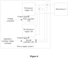
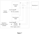
- a power supply system 1 includes a first power supply 110, a second power supply 120, a first controller 130 and a second controller 140.
- An output end of the first power supply 110 is connected in series with an output end of the second power supply 120 to form a series branch, and then the series branch is connected with a power input end of an electrolyzer 2.
- an output end of the power supply system is connected in series with a current sensor A, and the output end of the power supply system is connected in parallel with a voltage sensor V.
- the first controller 130 is configured to acquire a basic electric energy command, and control the first power supply 110 to output an expected DC electric signal according to the basic electric energy command.
- the second controller 140 is configured to acquire an impedance scanning electric energy command, and control the second power supply 120 to output an expected AC electric signal according to the impedance scanning electric energy command.
- the outputted voltage vector acquired by the voltage sensor and the outputted current vector acquired by the current sensor may be transmitted to the first controller 130, so that the first controller calculates an impedance value of the electrolyzer according to the outputted voltage vector and the outputted current vector.
- the second controller 140 receives the outputted voltage vector and the outputted current vector, and calculates the impedance value of the electrolyzer according to the outputted voltage vector and the outputted current vector.
- the functions of the first controller 130 and the second controller 140 may be integrated into one controller, thereby reducing the hardware cost.
- both the basic electric energy command and the impedance scanning electric energy command are voltage commands, that is, the first controller and the second controller are configured to control voltage signals outputted by the power supply system.
- the DC electric signal required for the normal operation of the electrolyzer is provided and controlled according to the actual gas production demand of the electrolyzer by using the first power supply and the first controller.
- the AC electric signals for impedance scanning are provided by using the second power supply and the second controller.
- the second power supply and the second controller are integrated into an impedance monitoring device independent of the first power supply and the first controller.
- the impedance monitoring device only provides the AC component signals for impedance scanning, which does not require a wire embedded in the electrolyzer in advance, or an extra device for measuring an electric signal.
- both the basic electric energy command and the impedance scanning electric energy command are current commands.
- the first controller is configured to control a DC current signal outputted by the first power supply according to the basic electric energy command.
- the second controller is configured to control an AC current signal outputted by the second power supply according to the impedance scanning electric energy command.
- the functions of the first controller and the second controller may be integrated into one controller, thereby reducing the hardware cost.
- the second power supply and the second controller may also be integrated into an independent impedance monitoring device.
- the first power supply and the second power supply can operate independently of each other.
- the second power supply and the second controller may be integrated into an independent impedance monitoring device that can be applied to multiple electrolyzers, which is convenient and universal.
- a controller is further provided according to the present disclosure.
- the controller includes a processor and a memory.
- the memory stores a program executable by the processor.
- the processor is configured to execute the program stored in the memory, to perform the above method for monitoring impedance of an electrolyzer.
- a storage medium for a computer device is further provided according to the present disclosure.
- the storage medium stores a program.
- the program when being executed by the computer device, performs the above method for monitoring impedance of an electrolyzer.
- modules and sub-modules in the device and the terminal according to the embodiments of the present disclosure may be adjusted, divided or removed according to actual requirements.
- the modules or sub-modules described as a separate component may be or may be not separated physically.
- the component displayed as a module or sub-module may be or may be not a physical module or a physical sub-module, that is, may be located at one place or may be distributed on multiple network modules or multiple network sub-modules.
- the object of the solution of the embodiment may be achieved by selecting a part or all of the modules or the sub-modules according to the actual requirements.
- modules or sub-modules in different embodiments of the present disclosure may be integrated into one processing module, or may be separate physical modules or sub-modules respectively.
- two or more modules or sub-modules may be integrated into one module.
- the integrated module or sub-module may be implemented in a form of hardware, or may be implemented in a form of a software functional module or sub-module.
Landscapes
- Chemical & Material Sciences (AREA)
- Engineering & Computer Science (AREA)
- Automation & Control Theory (AREA)
- Chemical Kinetics & Catalysis (AREA)
- Electrochemistry (AREA)
- Materials Engineering (AREA)
- Metallurgy (AREA)
- Organic Chemistry (AREA)
- Physics & Mathematics (AREA)
- General Physics & Mathematics (AREA)
- Analytical Chemistry (AREA)
- Electrolytic Production Of Non-Metals, Compounds, Apparatuses Therefor (AREA)
Claims (8)
- Verfahren zum Überwachen der Impedanz eines Elektrolyseurs, wobei der Elektrolyseur mit einer Leistungsversorgung verbunden ist und das Verfahren Folgendes umfasst:Erfassen (S110) eines Grundelektroenergiebefehls und eines Elektroenergiebefehls zur Impedanzabtastung;Steuern (S120), gemäß dem Grundelektroenergiebefehl und dem Elektroenergiebefehl zur Impedanzabtastung, der Leistungsversorgung, um ein erwartetes elektrisches Signal auszugeben, wobei das erwartete elektrische Signal ein Gleichstrom-Komponentensignal, DC-Komponentensignal, und Wechselstrom-Komponentensignale, AC-Komponentensignale, umfasst, das DC-Komponentensignal für den normalen Betrieb des Elektrolyseurs verwendet wird und Frequenzen der AC-Komponentensignale voreingestellte Frequenzen im Elektroenergiebefehl zur Impedanzabtastung sind;Erfassen (S130), für jede der voreingestellten Frequenzen, eines Spannungsvektors und eines Stromvektors, die von der Leistungsversorgung bei der Ausgabe des DC-Komponentensignals und eines AC-Komponentensignals mit der voreingestellten Frequenz ausgegeben werden; undBerechnen (S140), für jede der voreingestellten Frequenzen, gemäß dem ausgegebenen Spannungsvektor und dem ausgegebenen Stromvektor, eines Impedanzwerts des Elektrolyseurs entsprechend der voreingestellten Frequenz,wobei das Verfahren dadurch gekennzeichnet ist, dass die Leistungsversorgung eine erste Leistungsversorgung und eine zweite Leistungsversorgung umfasst, und das Steuern (S120), gemäß dem Grundelektroenergiebefehl und dem Elektroenergiebefehl zur Impedanzabtastung, der Leistungsversorgung, um ein erwartetes elektrisches Signals auszugeben, Folgendes umfasst:Steuern, gemäß dem Grundelektroenergiebefehl, der ersten Leistungsversorgung, um das DC-Komponentensignal in dem erwarteten elektrischen Signal auszugeben; undSteuern, gemäß dem Elektroenergiebefehl zur Impedanzabtastung, der zweiten Leistungsversorgung, um nacheinander die AC-Komponentensignale mit den jeweils voreingestellten Frequenzen auszugeben.
- Verfahren nach Anspruch 1, wobeider Grundelektroenergiebefehl verwendet wird, um ein DC-Spannungssignal zu steuern, das von der ersten Leistungsversorgung ausgegeben wird, und der Elektroenergiebefehl zur Impedanzabtastung verwendet wird, um ein AC-Spannungssignal zu steuern, das von der zweiten Leistungsversorgung ausgegeben wird; oderder Grundelektroenergiebefehl verwendet wird, um ein DC-Stromsignal zu steuern, das von der ersten Leistungsversorgung ausgegeben wird, und der Elektroenergiebefehl zur Impedanzabtastung verwendet wird, um ein AC-Stromsignal zu steuern, das von der zweiten Leistungsversorgung ausgegeben wird.
- Verfahren nach Anspruch 2, wobei
der Grundelektroenergiebefehl verwendet wird, um ein DC-Leistungssignal zu steuern, das von der ersten Leistungsversorgung ausgegeben wird, und der Elektroenergiebefehl zur Impedanzabtastung verwendet wird, um ein AC-Leistungssignal zu steuern, das von der zweiten Leistungsversorgung ausgegeben wird. - Verfahren nach Anspruch 1, wobei das Erfassen, für jede der voreingestellten Frequenzen, eines Spannungsvektors und eines Stromvektors, die von der Leistungsversorgung bei der Ausgabe des DC-Komponentensignals und eines AC-Komponentensignals mit der voreingestellten Frequenz ausgegeben werden, Folgendes umfasst:Empfangen des Spannungsvektors von einem Spannungssensor, der mit einem Ausgangsende der Leistungsversorgung verbunden ist; undEmpfangen des Stromvektors von einem Stromsensor, der mit dem Ausgangsende der Leistungsversorgung verbunden ist.
- Steuergerät zur Überwachung der Impedanz eines Elektrolyseurs, umfassend:einen Speicher, auf dem ein Programm gespeichert ist; undeinen Prozessor, der dazu konfiguriert ist, das Programm auszuführen, um das Verfahren zum Überwachen der Impedanz eines Elektrolyseurs nach einem der Ansprüche 1 bis 4 durchzuführen.
- Leistungsversorgungssystem (1) für einen Elektrolyseur (2), umfassend:eine Leistungsversorgung (11), wobei ein Ausgangsende der Leistungsversorgung (11) mit einem Spannungssensor und einem Stromsensor verbunden ist und das Ausgangsende der Leistungsversorgung (11) mit einem Leistungseingangsende des Elektrolyseurs verbunden ist; undein Steuergerät (12), das zu Folgendem konfiguriert ist:Erfassen eines Grundelektroenergiebefehls und eines Elektroenergiebefehls zur Impedanzabtastung;Steuern, gemäß dem Grundelektroenergiebefehl und dem Elektroenergiebefehl zur Impedanzabtastung, der Leistungsversorgung (11), um ein erwartetes elektrisches Signal auszugeben, wobei das erwartete elektrische Signal ein Gleichstrom-Komponentensignal, DC-Komponentensignal, und Wechselstrom-Komponentensignale, AC-Komponentensignale, umfasst, das DC-Komponentensignal für den normalen Betrieb des Elektrolyseurs verwendet wird und Frequenzen der AC-Komponentensignale voreingestellte Frequenzen im Elektroenergiebefehl zur Impedanzabtastung sind;Erfassen, für jede der voreingestellten Frequenzen, eines Spannungsvektors und eines Stromvektors, die von der Leistungsversorgung (11) bei der Ausgabe des DC-Komponentensignals und eines AC-Komponentensignals mit der voreingestellten Frequenz ausgegeben werden; undBerechnen, für jede der voreingestellten Frequenzen, gemäß dem ausgegebenen Spannungsvektor und dem ausgegebenen Stromvektor, eines Impedanzwerts des Elektrolyseurs entsprechend der voreingestellten Frequenz,wobei das Leistungsversorgungssystem (1) dadurch gekennzeichnet ist, dass:die Leistungsversorgung (11) eine erste Leistungsversorgung (110) und eine zweite Leistungsversorgung (120) umfasst; unddas Steuergerät (12) zu Folgendem konfiguriert ist:Steuern, gemäß dem Grundelektroenergiebefehl, der ersten Leistungsversorgung (110), um das DC-Komponentensignal in dem erwarteten elektrischen Signal auszugeben; undSteuern, gemäß dem Elektroenergiebefehl zur Impedanzabtastung, der zweiten Leistungsversorgung (120), um nacheinander die AC-Komponentensignale mit den jeweils voreingestellten Frequenzen auszugeben.
- Leistungsversorgungssystem (1) nach Anspruch 6, wobei das Steuergerät (12) ein erstes Steuergerät (130) und ein zweites Steuergerät (140) umfasst, wobei das erste Steuergerät (130) dazu konfiguriert ist, ein DC-Spannungssignal, ein DC-Stromsignal oder ein DC-Leistungssignal, die von der ersten Leistungsversorgung (110) ausgegeben werden, gemäß dem Grundelektroenergiebefehl zu steuern; und das zweite Steuergerät (140) dazu konfiguriert ist, ein AC-Spannungssignal, ein AC-Stromsignal oder ein AC-Leistungssignal, die von der zweiten Leistungsversorgung (120) ausgegeben werden, gemäß dem Elektroenergiebefehl zur Impedanzabtastung zu steuern.
- Leistungsversorgungssystem (1) nach Anspruch 7, wobei die zweite Leistungsversorgung (120) und das zweite Steuergerät in eine Impedanzüberwachungsvorrichtung unabhängig von der ersten Leistungsversorgung (110) und dem ersten Steuergerät integriert sind.
Applications Claiming Priority (1)
| Application Number | Priority Date | Filing Date | Title |
|---|---|---|---|
| CN202011407054.1A CN112782480A (zh) | 2020-12-04 | 2020-12-04 | 一种电解槽阻抗监测方法、控制器及供电电源 |
Publications (3)
| Publication Number | Publication Date |
|---|---|
| EP4008807A1 EP4008807A1 (de) | 2022-06-08 |
| EP4008807B1 true EP4008807B1 (de) | 2023-10-04 |
| EP4008807C0 EP4008807C0 (de) | 2023-10-04 |
Family
ID=75750726
Family Applications (1)
| Application Number | Title | Priority Date | Filing Date |
|---|---|---|---|
| EP21179371.6A Active EP4008807B1 (de) | 2020-12-04 | 2021-06-14 | Verfahren zur überwachung der impedanz eines elektrolyseurs, steuergerät und stromversorgung |
Country Status (3)
| Country | Link |
|---|---|
| US (1) | US20220178037A1 (de) |
| EP (1) | EP4008807B1 (de) |
| CN (1) | CN112782480A (de) |
Families Citing this family (5)
| Publication number | Priority date | Publication date | Assignee | Title |
|---|---|---|---|---|
| CN116791147A (zh) * | 2022-03-15 | 2023-09-22 | 国家能源投资集团有限责任公司 | 电解槽阻抗检测方法、装置和电解水制氢装置 |
| AU2023306752B2 (en) * | 2022-07-15 | 2026-04-09 | Asahi Kasei Kabushiki Kaisha | Operation support device, operation support method and operation support program |
| DE102024207266A1 (de) | 2024-07-31 | 2026-02-05 | Hochschule Bonn-Rhein-Sieg, Körperschaft des öffentlichen Rechts | Vorrichtung zur Beaufschlagung eines Elektrolyseurs mit elektrischer Energie und Messung von zumindest einem Impedanzwert des Elektrolyseurs und Verfahren hierfür |
| CN120294419B (zh) * | 2025-04-22 | 2026-01-30 | 湖北英特利电气有限公司 | 一种考虑动态扰动的电解槽阻抗测量方法及系统 |
| CN120666398A (zh) * | 2025-05-27 | 2025-09-19 | 四川大学 | 一种主动控制的多时间尺度的电解槽阻抗检测方法 |
Family Cites Families (18)
| Publication number | Priority date | Publication date | Assignee | Title |
|---|---|---|---|---|
| RO75812A (ro) * | 1974-06-05 | 1981-02-28 | Aluminium Pechiney,Fr | Procedeu pentru determinarea continua a resistentei interne a unei cuve de electroliza si instalatie pentru aplicarea procedeului |
| EP1730541A2 (de) * | 2004-03-26 | 2006-12-13 | Eaton Power Quality Company | Verfahren zum testen einer elektrochemischen einrichtung |
| JP2008522350A (ja) * | 2004-11-29 | 2008-06-26 | ハイドロジェニクス コーポレイション | 電気化学電池の故障状態を検出し表示するためのシステムおよび方法 |
| CN101221223B (zh) * | 2007-12-27 | 2011-03-16 | 武汉理工大学 | 一种燃料电池堆单片电池内阻与电压在线测试系统 |
| CN104007146B (zh) * | 2014-05-30 | 2016-04-13 | 深圳市赛亿科技开发有限公司 | 电解程度分析方法、控制方法及制取弱碱性水的设备 |
| TWI579575B (zh) * | 2016-03-23 | 2017-04-21 | 高苑科技大學 | Battery health detection method and its circuit |
| CN106324355B (zh) * | 2016-09-19 | 2019-03-01 | 清华大学 | 电化学装置的交流阻抗测试系统及方法 |
| CN107192884B (zh) * | 2017-06-08 | 2019-06-18 | 清华大学 | 一种基于交流阻抗测试的太阳能电池串联电阻的测量方法 |
| CN108107090A (zh) * | 2017-11-09 | 2018-06-01 | 国家电网公司 | 一种固态聚合物电解质水电解池膜电极污染的检测方法 |
| CN108998813A (zh) * | 2018-07-25 | 2018-12-14 | 北方工业大学 | 一种测量铝电解槽阳极电流的系统及方法 |
| CN109212431B (zh) * | 2018-09-19 | 2020-07-28 | 同济大学 | 一种燃料电池阻抗测量系统及方法 |
| JP7093079B2 (ja) * | 2018-10-26 | 2022-06-29 | 三菱重工業株式会社 | 水素及び酸素生成システム並びに水素及び酸素生成方法 |
| CN110231581A (zh) * | 2019-06-10 | 2019-09-13 | 哈尔滨佳云科技有限公司 | 蓄电池内阻测量电路及测量方法 |
| FI129353B (en) * | 2020-01-09 | 2021-12-31 | Lappeenrannan Lahden Teknillinen Yliopisto Lut | System and procedure for estimating the electrical properties of an electrolyser |
| CN111123135B (zh) * | 2020-01-14 | 2022-06-10 | 苏州英威腾电力电子有限公司 | 一种燃料电池内阻的在线辨识方法及系统 |
| AU2021220109B2 (en) * | 2020-02-14 | 2026-02-26 | HyGro Technology B.V. | AC to DC converter for electrolysis |
| TWI891829B (zh) * | 2020-06-26 | 2025-08-01 | 美商歐米恩國際公司 | 交流阻抗頻譜系統及方法 |
| US20220112612A1 (en) * | 2020-10-13 | 2022-04-14 | Analog Devices, Inc. | Parallel configuration of electrolysis cells |
-
2020
- 2020-12-04 CN CN202011407054.1A patent/CN112782480A/zh active Pending
-
2021
- 2021-06-14 EP EP21179371.6A patent/EP4008807B1/de active Active
- 2021-06-22 US US17/355,008 patent/US20220178037A1/en not_active Abandoned
Also Published As
| Publication number | Publication date |
|---|---|
| EP4008807A1 (de) | 2022-06-08 |
| CN112782480A (zh) | 2021-05-11 |
| EP4008807C0 (de) | 2023-10-04 |
| US20220178037A1 (en) | 2022-06-09 |
Similar Documents
| Publication | Publication Date | Title |
|---|---|---|
| EP4008807A1 (de) | Verfahren zur überwachung der impedanz eines elektrolyseurs, steuergerät und stromversorgung | |
| JP5780466B2 (ja) | 電気化学デバイスの具合状態の測定方法 | |
| CN102439471B (zh) | 通过阻抗谱表征电系统的特性的方法 | |
| EP2613164B1 (de) | Vorrichtung zur erzeugung einer verteilten leistung und betriebsverfahren dafür | |
| KR101516419B1 (ko) | 연료전지용 전력변환장치 및 그 제어방법 | |
| KR20120033197A (ko) | 발전기 자동전압 조정장치와 관련 주변설비의 고장진단장치 및 그 진단방법 | |
| US20250093422A1 (en) | A method for quality testing of a battery and a battery formation system | |
| CN218068220U (zh) | 浮动vi源板卡报警装置及系统 | |
| CN117117970A (zh) | 一种变流器的控制方法、装置及储能系统 | |
| CN117129791A (zh) | 一种配网侧电能质量监测装置 | |
| US11315083B2 (en) | Asset management method for substation | |
| EP4553195A1 (de) | Steuerungsvorrichtung für wasserstoffherstellungsvorrichtung, wasserstoffherstellungsanlage, verfahren zur steuerung der wasserstoffherstellungsvorrichtung und steuerungsprogramm für die wasserstoffherstellungsvorrichtung | |
| JP7524565B2 (ja) | 電源装置および電源装置の劣化判定方法 | |
| WO2024094264A3 (en) | Improvements relating to hydrogen electrolysis systems | |
| CN212275908U (zh) | 一种双馈风电机组发电机在线绝缘检测装置 | |
| CN117686117A (zh) | 温升故障诊断方法、装置、存储介质、控制装置及开关柜 | |
| JP2002325462A (ja) | 太陽光発電用電力変換装置 | |
| CN119298117B (zh) | 一种智能反馈调节的三相电源平衡输出方法及系统 | |
| CN121656858A (zh) | 一种宽频多域燃料电池电堆交流阻抗测试方法 | |
| JP2020058179A (ja) | 電力出力装置 | |
| EP4654415A1 (de) | Verfahren zur flackerbeurteilung für ein elektrolysesystem | |
| US20230420983A1 (en) | Method and system of detection of dropped loads resulting from an electrical power quality event | |
| CN118011100A (zh) | 一种开关柜导电回路电阻值在线监测方法、装置及预设的lstm模型 | |
| CN121677944A (zh) | 一种风电机组低压电气部件状态监测方法、装置及系统 | |
| CN121790447A (zh) | 一种基于dc-dc拓扑的燃料电池电堆交流阻抗检测方法 |
Legal Events
| Date | Code | Title | Description |
|---|---|---|---|
| PUAI | Public reference made under article 153(3) epc to a published international application that has entered the european phase |
Free format text: ORIGINAL CODE: 0009012 |
|
| STAA | Information on the status of an ep patent application or granted ep patent |
Free format text: STATUS: REQUEST FOR EXAMINATION WAS MADE |
|
| 17P | Request for examination filed |
Effective date: 20220310 |
|
| AK | Designated contracting states |
Kind code of ref document: A1 Designated state(s): AL AT BE BG CH CY CZ DE DK EE ES FI FR GB GR HR HU IE IS IT LI LT LU LV MC MK MT NL NO PL PT RO RS SE SI SK SM TR |
|
| RAP1 | Party data changed (applicant data changed or rights of an application transferred) |
Owner name: SUNGROW HYDROGEN SCI.&TECH. CO., LTD. |
|
| GRAP | Despatch of communication of intention to grant a patent |
Free format text: ORIGINAL CODE: EPIDOSNIGR1 |
|
| STAA | Information on the status of an ep patent application or granted ep patent |
Free format text: STATUS: GRANT OF PATENT IS INTENDED |
|
| INTG | Intention to grant announced |
Effective date: 20230609 |
|
| GRAS | Grant fee paid |
Free format text: ORIGINAL CODE: EPIDOSNIGR3 |
|
| GRAA | (expected) grant |
Free format text: ORIGINAL CODE: 0009210 |
|
| STAA | Information on the status of an ep patent application or granted ep patent |
Free format text: STATUS: THE PATENT HAS BEEN GRANTED |
|
| AK | Designated contracting states |
Kind code of ref document: B1 Designated state(s): AL AT BE BG CH CY CZ DE DK EE ES FI FR GB GR HR HU IE IS IT LI LT LU LV MC MK MT NL NO PL PT RO RS SE SI SK SM TR |
|
| REG | Reference to a national code |
Ref country code: GB Ref legal event code: FG4D |
|
| REG | Reference to a national code |
Ref country code: CH Ref legal event code: EP |
|
| REG | Reference to a national code |
Ref country code: IE Ref legal event code: FG4D |
|
| REG | Reference to a national code |
Ref country code: DE Ref legal event code: R096 Ref document number: 602021005558 Country of ref document: DE |
|
| U01 | Request for unitary effect filed |
Effective date: 20231019 |
|
| U07 | Unitary effect registered |
Designated state(s): AT BE BG DE DK EE FI FR IT LT LU LV MT NL PT SE SI Effective date: 20231027 |
|
| PG25 | Lapsed in a contracting state [announced via postgrant information from national office to epo] |
Ref country code: GR Free format text: LAPSE BECAUSE OF FAILURE TO SUBMIT A TRANSLATION OF THE DESCRIPTION OR TO PAY THE FEE WITHIN THE PRESCRIBED TIME-LIMIT Effective date: 20240105 |
|
| PG25 | Lapsed in a contracting state [announced via postgrant information from national office to epo] |
Ref country code: IS Free format text: LAPSE BECAUSE OF FAILURE TO SUBMIT A TRANSLATION OF THE DESCRIPTION OR TO PAY THE FEE WITHIN THE PRESCRIBED TIME-LIMIT Effective date: 20240204 |
|
| PG25 | Lapsed in a contracting state [announced via postgrant information from national office to epo] |
Ref country code: ES Free format text: LAPSE BECAUSE OF FAILURE TO SUBMIT A TRANSLATION OF THE DESCRIPTION OR TO PAY THE FEE WITHIN THE PRESCRIBED TIME-LIMIT Effective date: 20231004 |
|
| PG25 | Lapsed in a contracting state [announced via postgrant information from national office to epo] |
Ref country code: IS Free format text: LAPSE BECAUSE OF FAILURE TO SUBMIT A TRANSLATION OF THE DESCRIPTION OR TO PAY THE FEE WITHIN THE PRESCRIBED TIME-LIMIT Effective date: 20240204 Ref country code: GR Free format text: LAPSE BECAUSE OF FAILURE TO SUBMIT A TRANSLATION OF THE DESCRIPTION OR TO PAY THE FEE WITHIN THE PRESCRIBED TIME-LIMIT Effective date: 20240105 Ref country code: ES Free format text: LAPSE BECAUSE OF FAILURE TO SUBMIT A TRANSLATION OF THE DESCRIPTION OR TO PAY THE FEE WITHIN THE PRESCRIBED TIME-LIMIT Effective date: 20231004 |
|
| PG25 | Lapsed in a contracting state [announced via postgrant information from national office to epo] |
Ref country code: RS Free format text: LAPSE BECAUSE OF FAILURE TO SUBMIT A TRANSLATION OF THE DESCRIPTION OR TO PAY THE FEE WITHIN THE PRESCRIBED TIME-LIMIT Effective date: 20231004 Ref country code: PL Free format text: LAPSE BECAUSE OF FAILURE TO SUBMIT A TRANSLATION OF THE DESCRIPTION OR TO PAY THE FEE WITHIN THE PRESCRIBED TIME-LIMIT Effective date: 20231004 Ref country code: NO Free format text: LAPSE BECAUSE OF FAILURE TO SUBMIT A TRANSLATION OF THE DESCRIPTION OR TO PAY THE FEE WITHIN THE PRESCRIBED TIME-LIMIT Effective date: 20240104 Ref country code: HR Free format text: LAPSE BECAUSE OF FAILURE TO SUBMIT A TRANSLATION OF THE DESCRIPTION OR TO PAY THE FEE WITHIN THE PRESCRIBED TIME-LIMIT Effective date: 20231004 |
|
| REG | Reference to a national code |
Ref country code: DE Ref legal event code: R097 Ref document number: 602021005558 Country of ref document: DE |
|
| PG25 | Lapsed in a contracting state [announced via postgrant information from national office to epo] |
Ref country code: CZ Free format text: LAPSE BECAUSE OF FAILURE TO SUBMIT A TRANSLATION OF THE DESCRIPTION OR TO PAY THE FEE WITHIN THE PRESCRIBED TIME-LIMIT Effective date: 20231004 |
|
| PG25 | Lapsed in a contracting state [announced via postgrant information from national office to epo] |
Ref country code: SK Free format text: LAPSE BECAUSE OF FAILURE TO SUBMIT A TRANSLATION OF THE DESCRIPTION OR TO PAY THE FEE WITHIN THE PRESCRIBED TIME-LIMIT Effective date: 20231004 |
|
| PG25 | Lapsed in a contracting state [announced via postgrant information from national office to epo] |
Ref country code: SM Free format text: LAPSE BECAUSE OF FAILURE TO SUBMIT A TRANSLATION OF THE DESCRIPTION OR TO PAY THE FEE WITHIN THE PRESCRIBED TIME-LIMIT Effective date: 20231004 Ref country code: SK Free format text: LAPSE BECAUSE OF FAILURE TO SUBMIT A TRANSLATION OF THE DESCRIPTION OR TO PAY THE FEE WITHIN THE PRESCRIBED TIME-LIMIT Effective date: 20231004 Ref country code: RO Free format text: LAPSE BECAUSE OF FAILURE TO SUBMIT A TRANSLATION OF THE DESCRIPTION OR TO PAY THE FEE WITHIN THE PRESCRIBED TIME-LIMIT Effective date: 20231004 Ref country code: CZ Free format text: LAPSE BECAUSE OF FAILURE TO SUBMIT A TRANSLATION OF THE DESCRIPTION OR TO PAY THE FEE WITHIN THE PRESCRIBED TIME-LIMIT Effective date: 20231004 |
|
| U20 | Renewal fee for the european patent with unitary effect paid |
Year of fee payment: 4 Effective date: 20240628 |
|
| PLBE | No opposition filed within time limit |
Free format text: ORIGINAL CODE: 0009261 |
|
| STAA | Information on the status of an ep patent application or granted ep patent |
Free format text: STATUS: NO OPPOSITION FILED WITHIN TIME LIMIT |
|
| 26N | No opposition filed |
Effective date: 20240705 |
|
| PG25 | Lapsed in a contracting state [announced via postgrant information from national office to epo] |
Ref country code: MC Free format text: LAPSE BECAUSE OF FAILURE TO SUBMIT A TRANSLATION OF THE DESCRIPTION OR TO PAY THE FEE WITHIN THE PRESCRIBED TIME-LIMIT Effective date: 20231004 |
|
| REG | Reference to a national code |
Ref country code: CH Ref legal event code: PL |
|
| PG25 | Lapsed in a contracting state [announced via postgrant information from national office to epo] |
Ref country code: IE Free format text: LAPSE BECAUSE OF NON-PAYMENT OF DUE FEES Effective date: 20240614 |
|
| PG25 | Lapsed in a contracting state [announced via postgrant information from national office to epo] |
Ref country code: CH Free format text: LAPSE BECAUSE OF NON-PAYMENT OF DUE FEES Effective date: 20240630 |
|
| U20 | Renewal fee for the european patent with unitary effect paid |
Year of fee payment: 5 Effective date: 20250630 |
|
| PG25 | Lapsed in a contracting state [announced via postgrant information from national office to epo] |
Ref country code: CY Free format text: LAPSE BECAUSE OF FAILURE TO SUBMIT A TRANSLATION OF THE DESCRIPTION OR TO PAY THE FEE WITHIN THE PRESCRIBED TIME-LIMIT; INVALID AB INITIO Effective date: 20210614 |
|
| GBPC | Gb: european patent ceased through non-payment of renewal fee |
Effective date: 20250614 |
|
| PG25 | Lapsed in a contracting state [announced via postgrant information from national office to epo] |
Ref country code: HU Free format text: LAPSE BECAUSE OF FAILURE TO SUBMIT A TRANSLATION OF THE DESCRIPTION OR TO PAY THE FEE WITHIN THE PRESCRIBED TIME-LIMIT; INVALID AB INITIO Effective date: 20210614 |
|
| PG25 | Lapsed in a contracting state [announced via postgrant information from national office to epo] |
Ref country code: GB Free format text: LAPSE BECAUSE OF NON-PAYMENT OF DUE FEES Effective date: 20250614 |