EP4008842B1 - Engin de chantier - Google Patents
Engin de chantier Download PDFInfo
- Publication number
- EP4008842B1 EP4008842B1 EP20872227.2A EP20872227A EP4008842B1 EP 4008842 B1 EP4008842 B1 EP 4008842B1 EP 20872227 A EP20872227 A EP 20872227A EP 4008842 B1 EP4008842 B1 EP 4008842B1
- Authority
- EP
- European Patent Office
- Prior art keywords
- load
- manipulation
- estimative
- criterion
- bucket
- Prior art date
- Legal status (The legal status is an assumption and is not a legal conclusion. Google has not performed a legal analysis and makes no representation as to the accuracy of the status listed.)
- Active
Links
Images



Classifications
-
- E—FIXED CONSTRUCTIONS
- E02—HYDRAULIC ENGINEERING; FOUNDATIONS; SOIL SHIFTING
- E02F—DREDGING; SOIL-SHIFTING
- E02F3/00—Dredgers; Soil-shifting machines
- E02F3/04—Dredgers; Soil-shifting machines mechanically-driven
- E02F3/28—Dredgers; Soil-shifting machines mechanically-driven with digging tools mounted on a dipper- or bucket-arm, i.e. there is either one arm or a pair of arms, e.g. dippers, buckets
- E02F3/36—Component parts
- E02F3/42—Drives for dippers, buckets, dipper-arms or bucket-arms
- E02F3/43—Control of dipper or bucket position; Control of sequence of drive operations
- E02F3/435—Control of dipper or bucket position; Control of sequence of drive operations for dipper-arms, backhoes or the like
-
- E—FIXED CONSTRUCTIONS
- E02—HYDRAULIC ENGINEERING; FOUNDATIONS; SOIL SHIFTING
- E02F—DREDGING; SOIL-SHIFTING
- E02F9/00—Component parts of dredgers or soil-shifting machines, not restricted to one of the kinds covered by groups E02F3/00 - E02F7/00
- E02F9/26—Indicating devices
- E02F9/264—Sensors and their calibration for indicating the position of the work tool
-
- E—FIXED CONSTRUCTIONS
- E02—HYDRAULIC ENGINEERING; FOUNDATIONS; SOIL SHIFTING
- E02F—DREDGING; SOIL-SHIFTING
- E02F3/00—Dredgers; Soil-shifting machines
- E02F3/04—Dredgers; Soil-shifting machines mechanically-driven
- E02F3/28—Dredgers; Soil-shifting machines mechanically-driven with digging tools mounted on a dipper- or bucket-arm, i.e. there is either one arm or a pair of arms, e.g. dippers, buckets
- E02F3/36—Component parts
- E02F3/42—Drives for dippers, buckets, dipper-arms or bucket-arms
- E02F3/43—Control of dipper or bucket position; Control of sequence of drive operations
- E02F3/435—Control of dipper or bucket position; Control of sequence of drive operations for dipper-arms, backhoes or the like
- E02F3/439—Automatic repositioning of the implement, e.g. automatic dumping, auto-return
Definitions
- the present invention relates to a work machine, such as a hydraulic excavator.
- Each of the hydraulic excavators includes a working device including: a boom; an arm; and a bucket.
- the hydraulic excavator performs a loading work for loading an object of a work, such as soil and sand, to a destination, e.g., a dump truck, on a work site.
- the loading work includes: a holding task (excavation task) of excavating the soil and sand by the backet and holding the excavated soil and sand by the bucket; a carrying task of carrying the soil and sand held by the bucket to a position above the dump truck which is the destination; and a discharge task (soil discharge task) of discharging the soil and sand from the bucket at the position above the dump truck.
- the hydraulic excavator is known to be mounted with a payload function.
- the payload function serves to measure a load of the soil and sand held by the bucket. Operative execution of the payload function in a loading operation to the dump truck by the hydraulic excavator enables calculation of an amount of the soil and sand loaded to the dump truck.
- Patent Literature 1 (i.e. JP 2018 - 188 831 A ) discloses a technology for properly grasping a load of an excavated matter loaded to a dump truck by accurately detecting a loading operation to the dump truck (Paragraph [0005] of Patent Literature 1).
- a hydraulic excavator disclosed in Patent Literature 1 an operation of the hydraulic excavator is determined as the loading operation of loading the excavated matter to the dump truck under the condition that the bucket has moved across a reference height level, and a load value of a load is determined by a loading determination unit (paragraphs [0104] to [0107] of Patent Literature 1).
- the reference height level is set by a user of the hydraulic excavator (paragraph [0044] of Patent Literature 1).
- a height level to which the bucket is raised for loading the soil and sand to the dump truck in the loading work differs depending on a situation of the work site. For instance, a height level difference between the ground where the hydraulic excavator is located and the ground where the dump truck is located in the loading work varies depending on a work site. Besides, a height level difference between a surface of the soil and sand which is an object of a work to be excavated by the bucket in the loading work and the ground where the dump truck is located varies depending on a work site. It is seen from these perspectives that the technology disclosed in Patent Literature 1 requires an operator of the hydraulic excavator to perform a cumbersome setting operation of changing the setting of the reference height level depending on a situation of the work site.
- US 2007/135985 A1 discloses a work machine with the features of the preamble of claim 1 and a method of loading a truck with material using a loader including determining a target load for a final pass. Thereby, a load of the object held by the attachment is acquired, when the load is determined as being excessive, a reduction manipulation is performed, and the resulting load is determined. The tasks may be repeated if required.
- the present invention has an object of providing a work machine which can acquire a load of an object to be discharged from an attachment, such as a bucket, at a position above a destination without a cumbersome setting operation depending on a situation of a work site.
- an attachment such as a bucket
- the work machine includes: a working device which includes an attachment for holding the object; a load acquisition section which acquires a load of the object held by the attachment; an estimative load determination part which determines, based on the load acquired by the load acquisition section, an estimative load of the object estimated to be discharged at the position above the destination in the discharge task when a predetermined estimative load determinative criterion is satisfied; an estimative load update part which updates, based on the load acquired by the load acquisition section after the estimative load is determined, the estimative load when a predetermined estimative load update criterion is satisfied; and a definitive load determination part which determines, when a predetermined definitive load determinative criterion for determining a definitive load of the object to be actually discharged at the position above the destination in the discharge task
- the estimative load determinative criterion includes at least one of a criterion that a predetermined first reduction manipulation is detected in the holding task and a criterion that the first reduction manipulation is detected after the holding task, the first reduction manipulation being for reducing an amount of the object held by the attachment, the estimative load update criterion includes a criterion that a predetermined second reduction manipulation is detected after the estimative load is determined, the second reduction manipulation being for reducing an amount of the object held by the attachment after a completion of the first reduction manipulation, the definitive load determinative criterion includes a criterion that the load acquired by the load acquisition section after the estimative load is determined is equal to or smaller than a predetermined load threshold, and the estimative load update criterion further includes a criterion that a time from the completion of the first reduction manipulation to a start of the second reduction manipulation is equal to or longer than a predetermined time threshold.
- Fig. 1 shows a hydraulic excavator which is an example of a work machine according to an embodiment of the present invention.
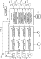
- Fig. 2 is a view showing a configuration of a controller mounted on the hydraulic excavator and a circuit controlled by the controller.
- a hydraulic excavator 10 includes: a lower traveling body 11; an upper slewing body 12 slewably mounted on the lower traveling body 11; a working device 13 mounted on the upper slewing body 12; a plurality of hydraulic actuators; at least one hydraulic pump 21; a pilot pump 22; a plurality of manipulation devices; a plurality of control valves; a plurality of pressure sensors; a posture detection part; and a controller 50.
- the lower traveling body 11 and the upper slewing body 12 constitute a machine body which supports the working device 13.
- the lower traveling body 11 has an unillustrated traveling device causing the hydraulic excavator 10 to travel, and thus can travel on the ground G.
- the upper slewing body 12 has a slewing frame 12A, and an engine room 12B and a cab 12C mounted thereon.
- the engine room 12B accommodates an engine
- the cab 12C has a seat which allows an operator to sit thereon, various manipulation levers, and various manipulation pedals.
- the working device 13 includes a plurality of movable parts which can perform a loading work for loading soil and sand to a dump truck.
- the movable parts include a boom 14, an arm 15, and a bucket 16.
- the soil and sand exemplifies an object of the work
- the dump truck exemplifies a destination
- the bucket 16 exemplifies an attachment.
- the loading work includes: a holding task (excavation task) of excavating the soil and sand and holding the excavated soil and sand by the bucket 16; a carrying task of carrying the soil and sand being held to a position above the dump track; and a discharge task (soil discharge task) of discharging the soil and sand at the position above the dump truck.
- the boom 14 has a proximal end supported on a front portion of the slewing frame 12A tiltably, i.e., rotatably about a horizontal axis, as indicated by arrow A1 in Fig. 1 , and a distal end opposite to the proximal end.
- the arm 15 has a proximal end attached to the distal end of the boom 14 rotatably about a horizontal axis as indicated by arrow A2 in Fig. 1 , and a distal end opposite to the proximal end.
- the bucket 16 is attached to the distal end of the arm 15 rotatably as indicated by arrow A3 in Fig. 1 .
- the hydraulic actuators include a plurality of hydraulic cylinders and a slewing motor 20.
- the hydraulic cylinders include at least one boom cylinder 17 which moves the boom 14, an arm cylinder 18 which moves the arm 15, and a bucket cylinder 19 which moves the bucket 16.
- Fig. 2 illustrates only the singe hydraulic pump 21, the hydraulic excavator 10 may include a plurality of hydraulic pumps.
- the at least one boom cylinder 17 is located between the upper slewing body 12 and the boom 14, and extends or contracts by receiving a supply of a hydraulic fluid discharged from the hydraulic pump 21 to thereby cause the boom 14 to rotate in a rising direction or a lowering direction indicated by the arrow A1.
- the arm cylinder 18 is located between the boom 14 and the arm 15, and extends or contracts by receiving a supply of the hydraulic fluid to thereby rotate the arm 15 in an arm pulling direction or an arm pushing direction indicated by the arrow A2.
- the arm pulling direction is a direction in which the distal end of the arm 15 moves closer to the boom 14, and the arm pushing direction is a direction in which the distal end of the arm 15 moves away from the boom 14.
- the bucket cylinder 19 is located between the arm 15 and the bucket 16, and extends or contracts by receiving a supply of the hydraulic fluid to thereby rotate the bucket 16 in a bucket pulling direction or a bucket pushing direction indicated by the arrow A3.
- the bucket pulling direction is a direction in which an angle ⁇ between a longitudinal direction 15a of the arm 15 shown in Fig. 1 and an edge 16a defining an opening of the bucket 16 decreases
- the bucket pushing direction is a direction in which the angle ⁇ increases.
- the manipulation devices include a boom manipulation device 61, an arm manipulation device 62, a bucket manipulation device 63, and a slewing manipulation device 64.
- the manipulation devices 61 to 64 respectively have manipulation levers 61A to 64A for each receiving a manipulation by the operator.
- Each of the manipulation devices may be constituted by a hydraulic manipulation device or an electric manipulation device.
- One manipulation lever may serve as a plurality of manipulation levers. For instance, a right manipulation lever located in front of the seat, which allows the operator to sit thereon, at a right position thereof may serve as a boom lever when manipulated in a front-rear direction, and serve as a bucket lever when manipulated in a left-right direction.
- a left manipulation lever located in front of the seat at a left position thereof may serve as an arm lever when manipulated in the front-rear direction, and serve as a slewing lever when manipulated in the left-right direction.
- Such lever patterns may be appropriately changed in response to a manipulation instruction from the operator.
- Fig. 2 shows a circuit configuration for the manipulation devices 61 to 64 each constituted by the electric manipulation device.
- the control valves include a boom control valve 41, an arm control valve 42, a bucket control valve 43, a slewing control valve 44, a pair of boom proportional solenoid valves 45, a pair of arm proportional solenoid valves 46, a pair of bucket proportional solenoid valves 47, and a pair of slewing proportional solenoid valves 48.
- a manipulation amount of the manipulation lever 63A is converted to an electric signal (manipulation signal) and the manipulation signal is input to the controller 50.
- the controller 50 inputs an instruction signal (instruction current) corresponding to the manipulation signal to either of the bucket proportional solenoid valves 47 that corresponds to the manipulation direction of the manipulation lever 63A.
- the corresponding bucket proportional solenoid valve 47 reduces a pressure of a pilot oil discharged from the pilot pump 22 in response to the instruction signal, and supplies the reduced pilot pressure to either of the pair of pilot ports of the bucket control valve 43.
- the bucket control valve 43 opens in a direction corresponding to the pilot port to which the pilot pressure is input at a stroke corresponding to the pilot pressure. This results in permitting the hydraulic fluid discharged from the hydraulic pump 21 to flow into a head chamber or a rod chamber of the bucket cylinder 19 at a flow rate corresponding to the stroke.
- Each of the manipulation levers of the remaining manipulation devices 61, 62, 64 is manipulated in the same manner as the case described above, and thus description therefor will be omitted.
- a hydraulic circuit for each manipulation device of a hydraulic type is unillustrated here, such a hydraulic circuit included in the hydraulic excavator 10 acts as described below.
- a pilot primary pressure from the pilot pump is reduced by a remote-control valve of the bucket manipulation device 63 depending on the manipulation amount of the manipulation lever 63A, and the reduced pilot pressure is output from the remote-control valve.
- the output pilot pressure is input to either of the pair of pilot ports of the bucket control valve.
- the bucket control valve opens in a direction corresponding to the pilot port to which the pilot pressure is input at a stroke corresponding to the pilot pressure. This results in permitting the hydraulic fluid discharged from the hydraulic pump to flow into the head chamber or the rod chamber of the bucket cylinder 19 at a flow rate corresponding to the stroke.
- the pressure sensors include a pressure sensor 35 which detects a head pressure of the boom cylinder 17 and a pressure sensor 36 which detects a rod pressure of the boom cylinder 17.
- the posture detection part includes a boom posture detector 31 which can detect a posture of the boom 14, an arm posture detector 32 which can detect a posture of the arm 15, and a bucket posture detector 33 which can detect a posture of the bucket 16.
- each of the posture detectors 31, 32, 33 is composed of, for example, an Inertial Measurement Unit (IMU).
- IMU Inertial Measurement Unit
- the posture of the boom 14, the posture of the arm 15, and the posture of the bucket 16 may be calculated, for example, based on a stroke value of a stroke of each of the boom cylinder 17, the arm cylinder 18, and the bucket cylinder 19 as detected by an unillustrated sensor.
- the posture of the boom 14, the posture of the arm 15, and the posture of the bucket 16 may be calculated, for example, based on a detection value obtained by a position detector utilizing a satellite positioning system, e.g., a GNSS sensor.
- the controller 50 (mechatronic controller) is composed of a computer including, for example, a CPU, a memory, and other elements, and operably has a manipulation determination part 51, a posture calculation part 52, a load calculation part 53, an estimative load determination part 54, an estimative load update part 55, a definitive load determination part 56, and a load information output part 57.
- the manipulation determination part 51 determines whether a manipulation is given to the manipulation lever of each of the manipulation devices 61 to 64.
- each of the manipulation devices 61 to 64 is constituted by the electric manipulation device as shown in Fig. 2
- each of the manipulation devices 61 to 64 inputs, to the controller 50, a manipulation signal corresponding to a manipulation amount given to the corresponding manipulation lever and a manipulation direction.
- the manipulation determination part 51 can determine that the manipulation is given to the corresponding manipulation lever of the manipulation device in response to the input manipulation signal.
- the manipulation determination part 51 can determine that: a boom raising manipulation of extending the boom cylinder 17 or a boom lowering manipulation of contracting the boom cylinder 17 is given to the manipulation lever 61A of the boom manipulation device 61; an arm pulling manipulation of extending the arm cylinder 18 or an arm pushing manipulation of contracting the arm cylinder 18 is given to the manipulation lever 62A of the arm manipulation device 62; a bucket pulling manipulation of extending the bucket cylinder 19 and a bucket pushing manipulation of contracting the bucket cylinder 19 are given to the manipulation lever 63A of the bucket manipulation device 63; and a right slewing manipulation or a left slewing manipulation of slewing the upper slewing body 12 is given to the manipulation lever 64A of the slewing manipulation device 64.
- the manipulation determination part 51 forms a manipulation detection part which can detect a manipulation given to each of the manipulation levers 61A to 64A of the manipulation devices 61 to 64
- the hydraulic excavator 10 includes a plurality of unillustrated pilot pressure sensors each detecting a pilot pressure output from the remote-control valve depending on a manipulation amount given to the corresponding manipulation lever of each of the manipulation devices 61 to 64.
- Each of the pilot pressure sensors inputs, to the controller 50, a manipulation signal corresponding to the detected pilot pressure.
- the manipulation determination part 51 can determine that the manipulation is given to the corresponding manipulation lever of the manipulation device in response to the input manipulation signal.
- the pilot pressure sensors and the manipulation determination part 51 form a manipulation detection part which can detect a manipulation given to each of the manipulation levers 61A to 64A of the manipulation devices 61 to 64.
- the posture calculation part 52 calculates each of the posture of the boom 14, the posture of the arm 15, and the posture of the bucket 16 in response to a posture signal input from the posture detection part.
- the load calculation part 53 calculates a load of the object held by the bucket 16 in the manner which will be described below.
- a way of calculating the load of the object is not limited to the following calculation way, and another known way is adoptable to calculate the load.
- the load calculation part 53 calculates the load of the object held by the bucket 16 by using the following Equation 1.
- M M 1 + M 2 + M 3 + W ⁇ L
- Equation (1) the sign "M” denotes a moment of the boom cylinder 17 around a boom foot pin.
- the sign “M1” denotes a moment of the boom 14 around a boom foot pin.
- the sign “M2” denotes a moment of the arm 15 around a boom foot pin.
- the sign “M3” denotes a moment of the bucket 16 around a boom foot pin.
- the sign “W” denotes a load of an object, such as soil and sand, held by the bucket 16.
- the sign “L” denotes a horizontal distance from the boom foot pin to the proximal end of the bucket 16.
- the moment M is calculated from the head pressure and the rod pressure of the boom cylinder 17.
- the moment M1 is calculated by a product of a distance between a gravity center of the boom 14 and the boom foot pin, and a weight of the boom 14.
- the moment M2 is calculated by a product of a distance between a gravity center of the arm 15 and the boom foot pin, and a weight of the arm 15.
- the moment M3 is calculated by a product of a distance between a gravity center of the bucket 16 and the boom foot pin, and a weight of the bucket.
- a position of the gravity center of the boom 14, a position of the gravity center of the arm 15, and a position of the gravity center of the bucket 16 are calculated, based on information about the posture of the working device 13 detected by the posture detection part.
- the head pressure of the boom cylinder 17 is detected by the pressure sensor 35, and the rod pressure of the boom cylinder 17 is detected by the pressure sensor 36.
- the horizontal distance L is calculated, based on the information about the posture of the working device 13 detected by the posture detection part.
- the posture detection part, the pressure sensors 35, 36, the posture calculation part 52, and the load calculation part 53 form a load acquisition section which acquires the load of the object held by the bucket 16.
- the estimative load determination part 54 determines an estimative load of the object estimated to be discharged at the position above the destination in the discharge task when a predetermined estimative load determinative criterion is satisfied.
- the estimative load determinative criterion includes a criterion that a first reduction manipulation of reducing an amount of the object held by the bucket 16 is detected after the holding task.
- the estimative load determinative criterion may include a criterion that the first reduction manipulation is detected in the carrying task after the holding task.
- each of the bucket pushing manipulation and the arm pushing manipulation is set as the first reduction manipulation in advance.
- the bucket pushing manipulation exemplifies an attachment discharge manipulation.
- Each of the bucket pushing manipulation and the arm pushing manipulation can correspond to a manipulation for executing a discharge amount adjustment and a manipulation for performing the discharge task.
- the discharge amount adjustment includes reducing an amount of soil and sand (object) held by the bucket 16 by discharging, from the bucket 16, a portion of the soil and sand held by the bucket 16, and adjusting the amount (discharge amount) of the object to be discharged at the position above the dump truck after the holding task.
- only one of the bucket pushing manipulation and the arm pushing manipulation may be set as the first reduction manipulation without the other of the manipulations.
- the estimative load determination part 54 determines the estimative load when the manipulation determination part 51 determines at least one of facts that the bucket pushing manipulation is given to the manipulation lever 63A and that the arm pushing manipulation is given to the manipulation lever 62A.
- the determination of the estimative load is made, based on a load acquired by the load acquisition section, at least one of times in a detection of the first reduction manipulation and before the detection of the first reduction manipulation.
- the estimative load determination part 54 may determine, in response to an input of at least one of the manipulation signal corresponding to the bucket pushing manipulation and the manipulation signal corresponding to the arm pushing manipulation to the controller 50, a load of the object (load of the object held by the bucket 16) acquired by the load acquisition section at the input of the at least one of the manipulation signals as the estimative load.
- the estimative load determination part 54 may determine, in response to the input of the at least one of the manipulation signals to the controller 50, a load acquired in a time from a completion of the holding task to the input of the at least one of the manipulation signals to the controller 50 as the estimative load.
- an average value of the plurality of loads may be determined as the estimative load, for example.
- the estimative load update part 55 updates, based on the load acquired by the load acquisition section after the estimative load is determined, the estimative load when a predetermined estimative load update criterion is satisfied.
- the estimative load update criterion includes: a criterion that a second reduction manipulation of reducing an amount of the object held by the bucket 16 is detected after the estimative load is determined; and a criterion that a time from a completion of the first reduction manipulation to a start of the second reduction manipulation is equal to or longer than a predetermined time threshold.
- the second reduction manipulation is the same as the first reduction manipulation.
- each of the bucket pushing manipulation and the arm pushing manipulation is set as the second reduction manipulation in advance.
- only one of the bucket pushing manipulation and the arm pushing manipulation may be set as the second reduction manipulation without the other of the manipulations.
- the estimative load update part 55 updates the estimative load when the manipulation determination part 51 determines at least one of facts that the bucket pushing manipulation is given to the manipulation lever 63A and that the arm pushing manipulation is given to the manipulation lever 62A, and when the time from the completion of the first reduction manipulation to the start of the second reduction manipulation is equal to or longer than the predetermined time threshold.
- the estimative load update part 55 is operative to measure an elapsed time from the completion of the first reduction manipulation to the start of the second reduction manipulation.
- the updating of the estimative load is performed, based on the load acquired by the load acquisition section after the estimative load is determined.
- the estimative load update part 55 may update the estimative load, in response to an input of at least one of the manipulation signal corresponding to the bucket pushing manipulation and the manipulation signal corresponding to the arm pushing manipulation to the controller 50, by revising the estimative load to a load of the object (load of the object held by the bucket 16) acquired by the load acquisition section at the input of the at least one of the manipulation signals.
- the estimative load update part 55 may update the estimative load, in response to the input of the at least one of the manipulation signals to the controller 50, by revising the estimative load to a load acquired in a time from the determination of the estimative load to the input of the at least one of the manipulation signals to the controller 50.
- the estimative load may be updated by revising the estimative load to an average value of the plurality of loads, for example.
- the definitive load determination part 56 determines, when a predetermined definitive load determinative criterion for definitively determining the estimative load as the load of the object is satisfied, the estimative load as a definitive load of the object.
- the definitive load determinative criterion includes a criterion that the load acquired by the load acquisition section after the estimative load is determined is equal to or smaller than a predetermined load threshold.
- the load threshold may be set to, for example, a value larger than zero. Specifically, a large portion of the soil and sand held by the bucket 16 drops from the bucket 16 to the dump truck in response to the bucket pushing manipulation in the discharge task (soil discharge task), but some of the soil and sand adhered to the bucket may occasionally remain at the bucket.
- the load threshold is set to a value larger than zero so that the definitive load determination part 56 can definitively determine the estimative load as the load of the object even in this occasion.
- the load threshold may be set to the value larger than zero in further consideration of the accuracy of the load acquired by the load acquisition section.
- the definitive load determination part 56 determines the estimative load determined by the estimative load determination part 54 as the definitive load at a time when the definitive load determinative criterion is satisfied before the estimative load is updated. In contrast, after the estimative load is determined, the definitive load determination part 56 determines the estimative load updated by the estimative load update part 55 as the definitive load of the object at a time when the definitive load determinative criterion is satisfied after the estimative load is updated. When the updating of the estimative load is repeated a plurality of times, the definitive load determination part 56 determines the latest estimative load updated by the estimative load update part 55 as the definitive load of the object.
- the load information output part 57 outputs information about the determined definitive load to the display device 70.
- the load information output part 57 may output, for example, the load of the soil and sand (object) held by the bucket 16 in the holding task in addition to the information about the definitive load in real time.
- the load information output part 57 may output, in the loading work, a cumulative value of the load of the soil and sand discharged to the dump truck, a target loading amount of the soil and sand to be discharged to the dump truck, and the number of times of the soil discharging to the dump truck.
- the display device 70 displays information, such as information about the input definitive load, thereon.
- the display device 70 may be arranged visibly by the operator in the cab 12C of the hydraulic excavator 10.
- the display device 70 displaying the various kinds of information allows the operator to grasp, in real time, a difference (remaining dischargeable amount of the object) from a target loading amount (loading target) to the dump truck at the time of displaying, and grasp the load of the soil and sand (object) held by the bucket 16 at the time of the displaying.
- the operator manipulates a specific manipulation lever of the corresponding manipulation device for the discharge amount adjustment to thereby drop a portion of the object from the bucket 16 and adjust the load of the object held by the bucket 16. Thereafter, the operator can load the soil and sand (object) in an amount closer to the target loading amount to the dump truck in the discharge task.
- the display device 70 may include a display for a personal computer or a mobile information terminal device located in a place different from the hydraulic excavator 10.
- Fig. 3 is a flowchart showing a control operation to be executed by the controller 50.
- the controller 50 executes the control operation including steps S2 to S7 shown in Fig. 3 in response to an input of a signal indicating a completion of the holding task in the loading work to the controller 50 (step S1).
- the signal indicating the completion of the holding task can cover various aspects depending on a specific content of the holding task, and thus is not particularly limited and covers the following specific examples.
- the loading work includes the holding task (excavation task), the carrying task, and the discharge task (soil discharge task).
- the holding task includes excavating soil and sand, and holding the excavated soil and sand by the bucket 16.
- the operator performs the boom raising manipulation, the arm pulling manipulation, and the bucket pulling manipulation while avoiding the slewing manipulation of slewing the upper slewing body 12.
- the carrying task to be performed subsequently to the holding task includes moving the bucket 16 holding the soil and sand toward a higher position than the dump truck thereabove while slewing the upper slewing body 12, for example, at an angle of around 90° in a plan view so that the bucket 16 reaches right above the dump truck.
- the controller 50 receives an input of a manipulation signal (slewing manipulation signal) indicating a manipulation of the manipulation lever 64A of the slewing manipulation device 64, and then the controller 50 determines that the holding task is completed (step S1).
- a manipulation signal indicating a manipulation of the manipulation lever 64A of the slewing manipulation device 64
- Fig. 4 is a graph showing an exemplary chronological change in a manipulation signal input to the controller 50 in the control operation shown in Fig. 3 and an exemplary chronological change in a load (load value) of the soil and sand (object) held by the bucket 16.
- Fig. 4 shows three pieces of data along their respective time axes (horizontal axes) arranged in the same manner.
- the upper data in Fig. 4 shows a chronological change in a manipulation signal (bucket pushing manipulation signal) of the bucket pushing manipulation given to the manipulation lever 63A of the bucket manipulation device 63 among the manipulation signals input to the controller 50.
- the bucket pushing manipulation is set as both the first reduction manipulation and the second reduction manipulation.
- the middle data in Fig. 4 shows a first pattern.
- the estimative load is determined (at a time point denoted by point A in Fig. 4 ) in response to the bucket pushing manipulation given to the manipulation lever 63A.
- the definitive load is determined when the definitive load determinative criterion is satisfied (at a time point denoted by point B in Fig. 4 ) before the estimative load is updated.
- the lower data in Fig. 4 shows a second pattern.
- the estimative load is determined (at a time point denoted by point C in Fig. 4 ) in response to the bucket pushing manipulation given to the manipulation lever 63A.
- the estimative load is updated (at a time point denoted by point E in Fig. 4 ).
- the definitive load is determined when the definitive load determinative criterion is satisfied (at a time point denoted by point F in Fig. 4 ).
- a total load value of the object to be discharged (soil and sand to be discharged) at the position above the dump truck reaches a target loading amount to the dump truck by repeating the loading work a plurality of times.
- Each of Fig. 5 and Fig. 6 shows an example of the loading work of the soil and sand as performed by the hydraulic excavator 10 and an example of contents displayed on the display device 70 through the control operation.
- Each of Fig. 5 and Fig. 6 further shows an exemplary case where a total load value ("loaded load” in Fig. 5 ) of the object reaches a target loading amount ("loading target" in Fig. 5 ) of 2.0 t under the condition that the loading work has been performed seven times heretofore, and that a discharge task (soil discharge task) in the subsequent eighth loading work will be further performed.
- the item “bucket load” represents a load of an object, such as soil and sand held by the bucket 16, to be calculated by the load calculation part 53.
- the item “loaded load” represents a total load value of the object loaded to a destination, such as the dump truck.
- Fig. 5 shows that the object of 1.94 t has been loaded in the discharge task (soil discharge task) heretofore.
- the item “loading target” represents a target amount of the object to be loaded to the destination, such as the dump truck.
- the item “number of times of loading” represents the number of times of the discharge task (soil discharge task) performed at the destination, such as the dump truck.
- the item “bucket load” is prominently displayed in the right section in Fig. 5 .
- the prominent displaying aims at notifying that loading of the soil and sand (the “bucket load” of 0.15 t) held by the bucket 16 at the destination, such as the dump truck, in a subsequent loading work (the eighth loading work) would exceed the loading target in the situation of the "loaded load” of 1.94 t at the completion of the seventh loading work.
- the prominent displaying is finished when the discharge amount adjustment is executed and the excess state is solved as shown in the lower section in Fig. 6 .
- the item "loaded load” may be prominently displayed as shown in Fig. 6 .
- the prominent displaying may include changing the display of the item in an appealing color, e.g., by flashing the item in red.
- the excess of load may be notified by a warning sound simultaneously, or by a guidance, such as a voice guidance.
- the operator determines, based on information, i.e., information without the prominent displaying, displayed on the display device 70, no necessity of the discharge amount adjustment, and thus performs the manipulation in the manner of the first pattern shown in Fig. 4 .
- the first pattern will be described with reference to the flowchart in Fig. 3 and the graph in Fig. 4 .
- the estimative load determination part 54 of the controller 50 determines whether the estimative load determinative criterion is satisfied (step S2). At the time point denoted by the point A in Fig. 4 , the estimative load determination part 54 determines that, in response to an input of the bucket pushing manipulation signal to the controller 50, the estimative load determinative criterion is satisfied (YES in step S2), and determines, for example, the load held by the bucket 16 and acquired by the load acquisition section at the time point as an estimative load (step S3). In the specific example shown in each of Fig. 4 to Fig. 6 , the estimative load in the seventh loading work is determined to 0.24 t.
- the definitive load determination part 56 determines whether the definitive load determinative criterion is satisfied (step S4). After the estimative load is determined, the definitive load determination part 56 determines that the definitive load determinative criterion is satisfied (YES in step S4) when the load acquired by the load acquisition section is equal to or smaller than the load threshold at the time point denoted by the point B in Fig. 4 , and further determines the estimative load as a definitive load (step S5). In the specific example shown in each of Fig. 4 to Fig. 6 , the definitive load in the seventh loading work is determined to 0.24 t.
- the operator determines, based on information (in the prominent displaying) displayed on the display device 70, the necessity of the discharge amount adjustment, and thus performs the manipulation in the manner of the second pattern shown in Fig. 4 .
- the second pattern will be described with reference to the flowchart in Fig. 3 and the graph in Fig. 4 .
- the estimative load determination part 54 of the controller 50 determines whether the estimative load determinative criterion is satisfied (step S2). At the time point denoted by the point C in Fig. 4 , the estimative load determination part 54 determines that, in response to an input of the bucket pushing manipulation signal to the controller 50, the estimative load determinative criterion is satisfied (YES in step S2), and further determines, for example, the load held by the bucket 16 and acquired by the load acquisition section at the time point as an estimative load (step S3). In the specific example shown in each of Fig. 4 to Fig. 6 , the estimative load in the eighth loading work is determined to 0.15 t.
- the definitive load determination part 56 determines whether the definitive load determinative criterion is satisfied (step S4).
- the load acquired by the load acquisition section in a period from the determination of the estimative load to the time point (denoted by the point E in Fig. 4 ) of a start of a subsequent bucket pushing manipulation is larger than the load threshold. Therefore, the definitive load determination part 56 determines that the definitive load determinative criterion is not satisfied (NO in step S4) and avoids determining the definitive load.
- the estimative load update part 55 determines whether the estimative load update criterion is satisfied (step S6).
- the controller 50 receives an input of a bucket pushing manipulation signal indicating that the subsequent bucket pushing manipulation is started at the time point denoted by the point E in Fig. 4 .
- an elapsed time e.g., 2 seconds in Fig. 4
- an elapsed time is equal to or longer than the time threshold.
- the estimative load update part 55 determines that the estimative load update criterion is satisfied (YES in step S6), and, for example, updates the estimative load by revising the estimative load to the load held by the bucket 16 and acquired by the load acquisition section at the time point (step S7).
- the estimative load in the eighth loading work is updated to 0.05 t.
- the estimative load is updated, based on the load acquired by the load acquisition section after the estimative load is determined.
- the definitive load determination part 56 determines whether the definitive load determinative criterion is satisfied (step S4). After the estimative load is determined (after the estimative load is updated), the definitive load determination part 56 determines that the definitive load determinative criterion is satisfied (YES in step S4) when the estimative load acquired by the load acquisition section is equal to or smaller than the load threshold at the time point denoted by the point F in Fig. 4 , and further determines the estimative load as the definitive load (step S5). In the specific example shown in each of Fig. 4 to Fig. 6 , the definitive load is determined to 0.05 t.
- the present invention should not be limited to the embodiment described above.
- the present invention covers, for example, aspects to be described below.
- the work machine is described as the hydraulic excavator 10 in the embodiment, but is not limited thereto and may be another work machine, e.g., a wheel loader.
- the estimative load update criterion includes a criterion (reduction manipulation criterion) that the second reduction manipulation of reducing the amount of the object held by the bucket 16 is detected after the estimative load is determined, and a criterion (time criterion) that a time from the completion of the first reduction manipulation to the start of the second reduction manipulation is equal to or longer than the predetermined time threshold in the embodiment, but is not limited thereto.
- the estimative load update criterion may include the reduction manipulation criterion and exclude the time criterion.
- the definitive load determinative criterion includes a criterion (load criterion) that the load acquired by the load acquisition section after the estimative load is determined is equal to or smaller than a predetermined load threshold in the embodiment, but is not limited thereto.
- the definitive load determinative criterion may include, for example, a criterion (angle criterion) that an angle of the bucket (e.g., a bucket angle ⁇ shown in Fig. 1 ) in the performing of the bucket pushing manipulation is equal to or larger than a predetermined angle threshold.
- the definitive load determinative criterion may include at least one of the load criterion and the angle criterion.
- the second reduction manipulation is the same as the first reduction manipulation in the embodiment, but is not limited thereto, and may differ from the first reduction manipulation.
- the attachment includes the bucket 16 in the embodiment, but is not limited thereto.
- the attachment may include other attachment, e.g., a fork, and a grapple.
- Each of the fork and the grapple serves as an attachment which can hold an object of a work.
- Each of the fork and the grapple includes a plurality of arms openable and closable to catch and hold the object of the work, like carrying goods and waste woods.
- the work machine 10 includes the estimative load update part 55 and the definitive load determination part 56, but can exclude the estimative load update part 55 and the definitive load determination part 56.
- the estimative load determination part determines the estimative load when the estimative load determinative criterion is satisfied in the carrying task after the completion of the holding task in the embodiment, but is not limited thereto.
- the estimative load determination part may determine the estimative load when the estimative load determinative criterion is satisfied in the holding task.
- the estimative load determinative criterion may be a criterion that the first reduction manipulation is detected in the holding task.
- the estimative load determinative criterion may include a criterion that the first reduction manipulation is detected in at least one of the holding task and the carrying task.
- the load of the object held by the attachment may be calculated, for example, based on a value detected by a sensor, such as a load cell sensor, attached to the attachment.
- the load acquisition section includes the sensor and a load calculation part which calculates, based on the value detected by the sensor, the load of the object.
- a work machine which performs a holding task of holding an object of a work, a carrying task of carrying the object being held to a position above a destination, and a discharge task of discharging the object at the position above the destination.
- the work machine includes: a working device which includes an attachment for holding the object; a load acquisition section which acquires a load of the object held by the attachment; and an estimative load determination part which determines, based on the load acquired by the load acquisition section, an estimative load of the object estimated to be discharged at the position above the destination in the discharge task when a predetermined estimative load determinative criterion is satisfied.
- the estimative load determinative criterion includes at least one of a criterion that a predetermined first reduction manipulation is detected in the holding task and a criterion that the first reduction manipulation is detected after the holding task, the first reduction manipulation being for reducing an amount of the object held by the attachment.
- the estimative load is determined when the estimative load determinative criterion including at least one of the criterion that the first reduction manipulation is detected in the holding task and the criterion that the first reduction manipulation is detected after the holding task is satisfied. Therefore, the estimative load of the object estimated to be discharged from the attachment at the position above the destination is acquirable without a cumbersome setting operation depending on a work site.
- the reduction manipulation includes reducing the amount of soil and sand (which is an example of the object) held by the bucket (which is an example of the attachment) by discharging, from the bucket, a portion of the soil and sand held by the bucket, and adjusting the amount (discharge amount) of the object to be discharged at the position above the dump truck (which is an example of the destination).
- the work machine preferably includes the configuration described below for the reduction manipulation.
- the work machine preferably further includes: an estimative load update part which updates, based on the load acquired by the load acquisition section after the estimative load is determined, the estimative load when a predetermined estimative load update criterion is satisfied; and a definitive load determination part which determines, when a predetermined definitive load determinative criterion for determining a definitive load of the object to be actually discharged at the position above the destination in the discharge task is satisfied, the estimative load as the definitive load.
- the estimative load update criterion preferably includes a criterion that a predetermined second reduction manipulation is detected after the estimative load is determined, the second reduction manipulation being for reducing, after a completion of the first reduction manipulation, an amount of the object held by the attachment.
- the estimative load is updated, based on the load acquired by the load acquisition section after the estimative load is determined. Accordingly, such occurrence of the difference between the estimative load and the load of the object to be actually discharged at the position above the destination is suppressible even when the second reduction manipulation is performed after the estimative load is determined.
- the definitive load determinative criterion may include a criterion that the load acquired by the load acquisition section after the estimative load is determined is equal to or smaller than a predetermined load threshold.
- the discharge task is determined as having been performed when the load reduces to reach a value equal to or smaller than the load threshold, and thus the estimative load can be determined as the definitive load.
- the estimative load update criterion preferably further includes a criterion that a time from the completion of the first reduction manipulation to a start of the second reduction manipulation is equal to or longer than a predetermined time threshold.
- the estimative load update part determines whether to update the estimative load, based on an elapsed time from the completion of the first reduction manipulation to the start of the second reduction manipulation. Specifically, when the elapsed time is equal to or longer than the time threshold, the first reduction manipulation and the second reduction manipulation are intermittent or discontinuous, and thus the first reduction manipulation is considered as a manipulation for adjusting the discharge amount. In this case, updating of the estimative load is necessary.
- the estimative load update part updates the estimative load when the estimative load update criterion including the criterion that the elapsed time is equal to or longer than the time threshold is satisfied.
- the estimative load update part avoids updating the estimative load when the elapsed time does not satisfy the criterion that the elapsed time is equal to or longer than the time threshold.
- updating of the estimative load is appropriately determinable by determination, based on the elapsed time, as to whether to update the estimative load as described above.
- an attachment discharge manipulation is preferably set as the first reduction manipulation, the attachment discharge manipulation being for causing the attachment to discharge at least a portion of the object held by the attachment.
- the attachment discharge manipulation can serve as a manipulation for executing a discharge amount adjustment of adjusting the discharge amount and a manipulation for performing the discharge task. Accordingly, in this aspect, the attachment discharge manipulation set as the first reduction manipulation leads to a more appropriate determination of the estimative load and a more appropriate determination as to whether to update the estimative load.
- the work machine may further include: a machine body which supports the working device.
- the working device may further include: a boom rotatably attached to the machine body; and an arm rotatably attached to a distal end of the boom and having a distal end to which the attachment is attached.
- the attachment may include a bucket.
- An arm pushing manipulation may be further set as the first reduction manipulation, the arm pushing manipulation being for pushing the arm in a direction in which the distal end of the arm moves away from the boom.
- the estimative load determination part may determine the estimative load when at least one of the attachment discharge manipulation and the arm pushing manipulation is detected.
- the arm pushing manipulation can serve as a manipulation for executing the discharge amount adjustment and a manipulation for performing the discharge task.
- the object such as the soil and sand
- each of the attachment discharge manipulation and the arm pushing manipulation is set as the first reduction manipulation.
- the estimative load is determined when at least one of the manipulations is detected. Consequently, determination of the estimative load is more appropriately made.
Landscapes
- Engineering & Computer Science (AREA)
- Mechanical Engineering (AREA)
- Mining & Mineral Resources (AREA)
- Civil Engineering (AREA)
- General Engineering & Computer Science (AREA)
- Structural Engineering (AREA)
- Operation Control Of Excavators (AREA)
- Component Parts Of Construction Machinery (AREA)
Claims (4)
- Machine de travail (10) qui effectue une tâche de tenue de tenir un objet d'un travail, une tâche de transport de transporter l'objet tenu jusqu'à une position au-dessus d'une destination, et une tâche de décharge de décharger l'objet à la position au-dessus de la destination, la machine de travail comprenant :un dispositif de travail (13) qui comporte un accessoire (16) pour tenir l'objet ;une section d'acquisition de charge (53) qui acquiert une charge de l'objet tenu par l'accessoire ; etune partie de détermination de la charge estimative (54) qui détermine, sur la base de la charge acquise par la section d'acquisition de charge (53), une charge estimative de l'objet estimé pour être déchargé à la position au-dessus de la destination dans la tâche de décharge lorsqu'un critère prédéterminé de détermination de la charge estimative est satisfait, caractérisée parune partie de mise à jour de la charge estimative (55) qui met à jour, sur la base de la charge acquise par la section d'acquisition de charge (53) après la détermination de la charge estimative, la charge estimative lorsqu'un critère prédéterminé de mise à jour de la charge estimative est satisfait ;une partie de détermination de la charge définitive (56) qui détermine, lorsqu'un critère prédéterminé de détermination de la charge définitive de l'objet à décharger effectivement à la position au-dessus de la destination dans la tâche de déchargement est satisfait, la charge estimative comme étant la charge définitive, dans laquellele critère de détermination de la charge estimative comporte au moins l'un des critères suivants : un critère selon lequel une première manipulation de réduction prédéterminée est détectée dans la tâche de tenue et un critère selon lequel la première manipulation de réduction est détectée après la tâche de tenue,la première manipulation de réduction étant destinée à réduire une quantité de l'objet tenu par l'accessoire (16),le critère de mise à jour de la charge estimative comporte un critère selon lequel une deuxième manipulation de réduction prédéterminée est détectée après la détermination de la charge estimative,la seconde manipulation de réduction étant destinée à réduire une quantité de l'objet tenu par l'accessoire après l'achèvement de la première manipulation de réduction,le critère de détermination de la charge définitive comporte un critère selon lequel la charge acquise par la section d'acquisition de charge (53) après la détermination de la charge estimative est égale ou inférieure à un seuil de charge prédéterminé, etle critère de mise à jour de la charge estimative comporte en outre un critère selon lequel un temps entre l'achèvement de la première manipulation de réduction et un début de la deuxième manipulation de réduction est égal ou supérieur à un seuil de temps prédéterminé.
- Machine de travail selon la revendication 1, dans laquelle
la deuxième manipulation de réduction est la même que la première manipulation de réduction. - Machine de travail selon la revendication 1 ou 2, dans laquelle
une manipulation de décharge de l'accessoire est définie comme la première manipulation de réduction, la manipulation de décharge de l'accessoire étant destinée à faire en sorte que l'accessoire (16) décharge au moins une partie de l'objet tenu par l'accessoire (16). - Machine de travail selon la revendication 3, comprenant en outre :un corps de machine (11, 12) qui supporte le dispositif de travail (13), dans laquellele dispositif de travail (13) comporte en outre :une flèche (14) attachée de manière rotative au corps de machine (12) ; etun bras (15) attaché de manière rotative à une extrémité distale de la flèche (14) et ayant une extrémité distale à laquelle l'accessoire (16) est attaché,l'accessoire (16) comporte un godet,une manipulation de poussée du bras est également définie comme la première manipulation de réduction, la manipulation de poussée du bras étant destinée à pousser le bras (15) dans une direction dans laquelle l'extrémité distale du bras s'éloigne de la flèche (14), etla partie de détermination de la charge estimative (54) détermine la charge estimative lorsqu'au moins l'une de la manipulation de décharge de l'accessoire et de la manipulation de poussée du bras est détectée.
Applications Claiming Priority (2)
| Application Number | Priority Date | Filing Date | Title |
|---|---|---|---|
| JP2019180424A JP7306201B2 (ja) | 2019-09-30 | 2019-09-30 | 作業機械 |
| PCT/JP2020/033302 WO2021065314A1 (fr) | 2019-09-30 | 2020-09-02 | Engin de chantier |
Publications (3)
| Publication Number | Publication Date |
|---|---|
| EP4008842A1 EP4008842A1 (fr) | 2022-06-08 |
| EP4008842A4 EP4008842A4 (fr) | 2022-11-09 |
| EP4008842B1 true EP4008842B1 (fr) | 2024-07-17 |
Family
ID=75270232
Family Applications (1)
| Application Number | Title | Priority Date | Filing Date |
|---|---|---|---|
| EP20872227.2A Active EP4008842B1 (fr) | 2019-09-30 | 2020-09-02 | Engin de chantier |
Country Status (5)
| Country | Link |
|---|---|
| US (1) | US12523002B2 (fr) |
| EP (1) | EP4008842B1 (fr) |
| JP (1) | JP7306201B2 (fr) |
| CN (1) | CN114341435B (fr) |
| WO (1) | WO2021065314A1 (fr) |
Families Citing this family (3)
| Publication number | Priority date | Publication date | Assignee | Title |
|---|---|---|---|---|
| JP7234891B2 (ja) * | 2019-09-30 | 2023-03-08 | コベルコ建機株式会社 | 作業機械 |
| JP7461265B2 (ja) * | 2020-09-30 | 2024-04-03 | 株式会社小松製作所 | 積込機械の制御システム、積込機械、及び積込機械の制御方法 |
| WO2024189757A1 (fr) * | 2023-03-14 | 2024-09-19 | 株式会社Earthbrain | Dispositif de traitement d'informations pour estimer une quantité de terre dans un godet d'une pelle à partir d'angles de flèche et de bras, pelle, procédé, et programme |
Family Cites Families (22)
| Publication number | Priority date | Publication date | Assignee | Title |
|---|---|---|---|---|
| JPS58162816A (ja) * | 1982-03-23 | 1983-09-27 | Caterpillar Mitsubishi Ltd | 荷役積載重量監視装置 |
| JPH0459572A (ja) | 1990-06-27 | 1992-02-26 | Sharp Corp | 循環式原稿供給装置を備える複写機 |
| JP3787046B2 (ja) * | 1999-09-17 | 2006-06-21 | 日立建機株式会社 | 油圧ショベルの作業量モニタ装置 |
| US6931772B2 (en) * | 2001-10-18 | 2005-08-23 | Hitachi Construction Machinery Co., Ltd. | Hydraulic shovel work amount detection apparatus, work amount detection method, work amount detection result display apparatus |
| AU2005227398B1 (en) | 2005-10-28 | 2006-04-27 | Leica Geosystems Ag | Method and apparatus for determining the loading of a bucket |
| US7627410B2 (en) * | 2005-12-12 | 2009-12-01 | Caterpillar Inc. | Machine payload measurement dial-a-load system |
| CN101467011B (zh) | 2006-04-20 | 2013-04-10 | Cmte开发有限公司 | 有效载荷的估算系统和方法 |
| NZ555187A (en) | 2007-05-15 | 2010-01-29 | Actronic Ltd | Weight estimation for excavator payloads |
| JP2010089633A (ja) | 2008-10-08 | 2010-04-22 | Caterpillar Japan Ltd | 作業量モニタリングシステム |
| JP2012035973A (ja) * | 2010-08-06 | 2012-02-23 | Ohbayashi Corp | 積込量管理システム及び積込量管理方法 |
| JP5529949B2 (ja) * | 2012-11-20 | 2014-06-25 | 株式会社小松製作所 | 作業機械及び作業管理システム |
| US9091586B2 (en) | 2013-03-29 | 2015-07-28 | Caterpillar Inc. | Payload determination system and method |
| JP6042358B2 (ja) * | 2014-01-28 | 2016-12-14 | 日立建機株式会社 | 建設機械における積載重量超過予測装置 |
| US20170113591A1 (en) * | 2015-10-27 | 2017-04-27 | Caterpillar Inc. | System and method for controlling movement of implement |
| JP2018021344A (ja) * | 2016-08-02 | 2018-02-08 | 株式会社小松製作所 | 作業車両の制御システム、制御方法、及び作業車両 |
| US10801177B2 (en) * | 2017-01-23 | 2020-10-13 | Built Robotics Inc. | Excavating earth from a dig site using an excavation vehicle |
| JP6986853B2 (ja) | 2017-04-28 | 2021-12-22 | 株式会社小松製作所 | 作業機械および作業機械の制御方法 |
| JP6868938B2 (ja) | 2017-08-24 | 2021-05-12 | 日立建機株式会社 | 建設機械の荷重計測システム |
| WO2019082397A1 (fr) * | 2017-10-27 | 2019-05-02 | 日立建機株式会社 | Dispositif d'accumulation de quantité de chargement et système d'accumulation de quantité de chargement |
| US20200308803A1 (en) * | 2019-03-25 | 2020-10-01 | Cnh Industrial America Llc | System and method for automatic weight monitoring and control during a material moving operation |
| CN114174596B (zh) * | 2019-09-18 | 2024-03-08 | 住友重机械工业株式会社 | 挖土机 |
| US12032350B2 (en) * | 2020-04-13 | 2024-07-09 | Caterpillar Global Mining Llc | Multi-phase material blend monitoring and control |
-
2019
- 2019-09-30 JP JP2019180424A patent/JP7306201B2/ja active Active
-
2020
- 2020-09-02 US US17/760,883 patent/US12523002B2/en active Active
- 2020-09-02 CN CN202080064649.3A patent/CN114341435B/zh active Active
- 2020-09-02 WO PCT/JP2020/033302 patent/WO2021065314A1/fr not_active Ceased
- 2020-09-02 EP EP20872227.2A patent/EP4008842B1/fr active Active
Also Published As
| Publication number | Publication date |
|---|---|
| JP2021055434A (ja) | 2021-04-08 |
| CN114341435A (zh) | 2022-04-12 |
| WO2021065314A1 (fr) | 2021-04-08 |
| EP4008842A4 (fr) | 2022-11-09 |
| CN114341435B (zh) | 2023-05-23 |
| JP7306201B2 (ja) | 2023-07-11 |
| EP4008842A1 (fr) | 2022-06-08 |
| US20220341123A1 (en) | 2022-10-27 |
| US12523002B2 (en) | 2026-01-13 |
Similar Documents
| Publication | Publication Date | Title |
|---|---|---|
| EP3763886B1 (fr) | Machine de travail | |
| EP3674487B1 (fr) | Engin de chantier | |
| KR102402518B1 (ko) | 작업 기계 | |
| EP4008842B1 (fr) | Engin de chantier | |
| US12000113B2 (en) | Work machine | |
| EP4092201B1 (fr) | Machine de travail | |
| US11408146B2 (en) | Work machine and method for controlling the same | |
| KR20220066157A (ko) | 작업 기계 및 작업 기계의 제어 방법 | |
| EP4012112B1 (fr) | Engin de chantier | |
| CN114599838A (zh) | 作业机械、计量方法、以及包括作业机械的系统 | |
| EP4101997B1 (fr) | Machine de travail | |
| US20240301652A1 (en) | Work machine | |
| JP7452342B2 (ja) | 情報提示装置及び作業機械 | |
| WO2026070388A1 (fr) | Dispositif de calcul de charge et engin de chantier comprenant celui-ci |
Legal Events
| Date | Code | Title | Description |
|---|---|---|---|
| STAA | Information on the status of an ep patent application or granted ep patent |
Free format text: STATUS: THE INTERNATIONAL PUBLICATION HAS BEEN MADE |
|
| PUAI | Public reference made under article 153(3) epc to a published international application that has entered the european phase |
Free format text: ORIGINAL CODE: 0009012 |
|
| STAA | Information on the status of an ep patent application or granted ep patent |
Free format text: STATUS: REQUEST FOR EXAMINATION WAS MADE |
|
| 17P | Request for examination filed |
Effective date: 20220304 |
|
| AK | Designated contracting states |
Kind code of ref document: A1 Designated state(s): AL AT BE BG CH CY CZ DE DK EE ES FI FR GB GR HR HU IE IS IT LI LT LU LV MC MK MT NL NO PL PT RO RS SE SI SK SM TR |
|
| A4 | Supplementary search report drawn up and despatched |
Effective date: 20221010 |
|
| RIC1 | Information provided on ipc code assigned before grant |
Ipc: E02F 9/26 20060101ALI20221004BHEP Ipc: E02F 9/20 20060101AFI20221004BHEP |
|
| DAV | Request for validation of the european patent (deleted) | ||
| DAX | Request for extension of the european patent (deleted) | ||
| GRAP | Despatch of communication of intention to grant a patent |
Free format text: ORIGINAL CODE: EPIDOSNIGR1 |
|
| STAA | Information on the status of an ep patent application or granted ep patent |
Free format text: STATUS: GRANT OF PATENT IS INTENDED |
|
| INTG | Intention to grant announced |
Effective date: 20240307 |
|
| GRAS | Grant fee paid |
Free format text: ORIGINAL CODE: EPIDOSNIGR3 |
|
| GRAA | (expected) grant |
Free format text: ORIGINAL CODE: 0009210 |
|
| STAA | Information on the status of an ep patent application or granted ep patent |
Free format text: STATUS: THE PATENT HAS BEEN GRANTED |
|
| AK | Designated contracting states |
Kind code of ref document: B1 Designated state(s): AL AT BE BG CH CY CZ DE DK EE ES FI FR GB GR HR HU IE IS IT LI LT LU LV MC MK MT NL NO PL PT RO RS SE SI SK SM TR |
|
| REG | Reference to a national code |
Ref country code: CH Ref legal event code: EP |
|
| REG | Reference to a national code |
Ref country code: DE Ref legal event code: R096 Ref document number: 602020034283 Country of ref document: DE |
|
| REG | Reference to a national code |
Ref country code: IE Ref legal event code: FG4D |
|
| REG | Reference to a national code |
Ref country code: LT Ref legal event code: MG9D |
|
| REG | Reference to a national code |
Ref country code: NL Ref legal event code: MP Effective date: 20240717 |
|
| PG25 | Lapsed in a contracting state [announced via postgrant information from national office to epo] |
Ref country code: PT Free format text: LAPSE BECAUSE OF FAILURE TO SUBMIT A TRANSLATION OF THE DESCRIPTION OR TO PAY THE FEE WITHIN THE PRESCRIBED TIME-LIMIT Effective date: 20241118 |
|
| REG | Reference to a national code |
Ref country code: AT Ref legal event code: MK05 Ref document number: 1704253 Country of ref document: AT Kind code of ref document: T Effective date: 20240717 |
|
| PG25 | Lapsed in a contracting state [announced via postgrant information from national office to epo] |
Ref country code: NL Free format text: LAPSE BECAUSE OF FAILURE TO SUBMIT A TRANSLATION OF THE DESCRIPTION OR TO PAY THE FEE WITHIN THE PRESCRIBED TIME-LIMIT Effective date: 20240717 |
|
| PG25 | Lapsed in a contracting state [announced via postgrant information from national office to epo] |
Ref country code: PT Free format text: LAPSE BECAUSE OF FAILURE TO SUBMIT A TRANSLATION OF THE DESCRIPTION OR TO PAY THE FEE WITHIN THE PRESCRIBED TIME-LIMIT Effective date: 20241118 Ref country code: NL Free format text: LAPSE BECAUSE OF FAILURE TO SUBMIT A TRANSLATION OF THE DESCRIPTION OR TO PAY THE FEE WITHIN THE PRESCRIBED TIME-LIMIT Effective date: 20240717 |
|
| PG25 | Lapsed in a contracting state [announced via postgrant information from national office to epo] |
Ref country code: NO Free format text: LAPSE BECAUSE OF FAILURE TO SUBMIT A TRANSLATION OF THE DESCRIPTION OR TO PAY THE FEE WITHIN THE PRESCRIBED TIME-LIMIT Effective date: 20241017 |
|
| PG25 | Lapsed in a contracting state [announced via postgrant information from national office to epo] |
Ref country code: GR Free format text: LAPSE BECAUSE OF FAILURE TO SUBMIT A TRANSLATION OF THE DESCRIPTION OR TO PAY THE FEE WITHIN THE PRESCRIBED TIME-LIMIT Effective date: 20241018 Ref country code: FI Free format text: LAPSE BECAUSE OF FAILURE TO SUBMIT A TRANSLATION OF THE DESCRIPTION OR TO PAY THE FEE WITHIN THE PRESCRIBED TIME-LIMIT Effective date: 20240717 Ref country code: PL Free format text: LAPSE BECAUSE OF FAILURE TO SUBMIT A TRANSLATION OF THE DESCRIPTION OR TO PAY THE FEE WITHIN THE PRESCRIBED TIME-LIMIT Effective date: 20240717 |
|
| PG25 | Lapsed in a contracting state [announced via postgrant information from national office to epo] |
Ref country code: BG Free format text: LAPSE BECAUSE OF FAILURE TO SUBMIT A TRANSLATION OF THE DESCRIPTION OR TO PAY THE FEE WITHIN THE PRESCRIBED TIME-LIMIT Effective date: 20240717 |
|
| PG25 | Lapsed in a contracting state [announced via postgrant information from national office to epo] |
Ref country code: LV Free format text: LAPSE BECAUSE OF FAILURE TO SUBMIT A TRANSLATION OF THE DESCRIPTION OR TO PAY THE FEE WITHIN THE PRESCRIBED TIME-LIMIT Effective date: 20240717 |
|
| PG25 | Lapsed in a contracting state [announced via postgrant information from national office to epo] |
Ref country code: IS Free format text: LAPSE BECAUSE OF FAILURE TO SUBMIT A TRANSLATION OF THE DESCRIPTION OR TO PAY THE FEE WITHIN THE PRESCRIBED TIME-LIMIT Effective date: 20241117 Ref country code: AT Free format text: LAPSE BECAUSE OF FAILURE TO SUBMIT A TRANSLATION OF THE DESCRIPTION OR TO PAY THE FEE WITHIN THE PRESCRIBED TIME-LIMIT Effective date: 20240717 |
|
| PG25 | Lapsed in a contracting state [announced via postgrant information from national office to epo] |
Ref country code: HR Free format text: LAPSE BECAUSE OF FAILURE TO SUBMIT A TRANSLATION OF THE DESCRIPTION OR TO PAY THE FEE WITHIN THE PRESCRIBED TIME-LIMIT Effective date: 20240717 |
|
| PG25 | Lapsed in a contracting state [announced via postgrant information from national office to epo] |
Ref country code: ES Free format text: LAPSE BECAUSE OF FAILURE TO SUBMIT A TRANSLATION OF THE DESCRIPTION OR TO PAY THE FEE WITHIN THE PRESCRIBED TIME-LIMIT Effective date: 20240717 Ref country code: RS Free format text: LAPSE BECAUSE OF FAILURE TO SUBMIT A TRANSLATION OF THE DESCRIPTION OR TO PAY THE FEE WITHIN THE PRESCRIBED TIME-LIMIT Effective date: 20241017 |
|
| PG25 | Lapsed in a contracting state [announced via postgrant information from national office to epo] |
Ref country code: RS Free format text: LAPSE BECAUSE OF FAILURE TO SUBMIT A TRANSLATION OF THE DESCRIPTION OR TO PAY THE FEE WITHIN THE PRESCRIBED TIME-LIMIT Effective date: 20241017 Ref country code: PL Free format text: LAPSE BECAUSE OF FAILURE TO SUBMIT A TRANSLATION OF THE DESCRIPTION OR TO PAY THE FEE WITHIN THE PRESCRIBED TIME-LIMIT Effective date: 20240717 Ref country code: NO Free format text: LAPSE BECAUSE OF FAILURE TO SUBMIT A TRANSLATION OF THE DESCRIPTION OR TO PAY THE FEE WITHIN THE PRESCRIBED TIME-LIMIT Effective date: 20241017 Ref country code: LV Free format text: LAPSE BECAUSE OF FAILURE TO SUBMIT A TRANSLATION OF THE DESCRIPTION OR TO PAY THE FEE WITHIN THE PRESCRIBED TIME-LIMIT Effective date: 20240717 Ref country code: IS Free format text: LAPSE BECAUSE OF FAILURE TO SUBMIT A TRANSLATION OF THE DESCRIPTION OR TO PAY THE FEE WITHIN THE PRESCRIBED TIME-LIMIT Effective date: 20241117 Ref country code: HR Free format text: LAPSE BECAUSE OF FAILURE TO SUBMIT A TRANSLATION OF THE DESCRIPTION OR TO PAY THE FEE WITHIN THE PRESCRIBED TIME-LIMIT Effective date: 20240717 Ref country code: GR Free format text: LAPSE BECAUSE OF FAILURE TO SUBMIT A TRANSLATION OF THE DESCRIPTION OR TO PAY THE FEE WITHIN THE PRESCRIBED TIME-LIMIT Effective date: 20241018 Ref country code: FI Free format text: LAPSE BECAUSE OF FAILURE TO SUBMIT A TRANSLATION OF THE DESCRIPTION OR TO PAY THE FEE WITHIN THE PRESCRIBED TIME-LIMIT Effective date: 20240717 Ref country code: ES Free format text: LAPSE BECAUSE OF FAILURE TO SUBMIT A TRANSLATION OF THE DESCRIPTION OR TO PAY THE FEE WITHIN THE PRESCRIBED TIME-LIMIT Effective date: 20240717 Ref country code: BG Free format text: LAPSE BECAUSE OF FAILURE TO SUBMIT A TRANSLATION OF THE DESCRIPTION OR TO PAY THE FEE WITHIN THE PRESCRIBED TIME-LIMIT Effective date: 20240717 Ref country code: AT Free format text: LAPSE BECAUSE OF FAILURE TO SUBMIT A TRANSLATION OF THE DESCRIPTION OR TO PAY THE FEE WITHIN THE PRESCRIBED TIME-LIMIT Effective date: 20240717 |
|
| PG25 | Lapsed in a contracting state [announced via postgrant information from national office to epo] |
Ref country code: DK Free format text: LAPSE BECAUSE OF FAILURE TO SUBMIT A TRANSLATION OF THE DESCRIPTION OR TO PAY THE FEE WITHIN THE PRESCRIBED TIME-LIMIT Effective date: 20240717 Ref country code: RO Free format text: LAPSE BECAUSE OF FAILURE TO SUBMIT A TRANSLATION OF THE DESCRIPTION OR TO PAY THE FEE WITHIN THE PRESCRIBED TIME-LIMIT Effective date: 20240717 Ref country code: SM Free format text: LAPSE BECAUSE OF FAILURE TO SUBMIT A TRANSLATION OF THE DESCRIPTION OR TO PAY THE FEE WITHIN THE PRESCRIBED TIME-LIMIT Effective date: 20240717 |
|
| REG | Reference to a national code |
Ref country code: DE Ref legal event code: R097 Ref document number: 602020034283 Country of ref document: DE |
|
| PG25 | Lapsed in a contracting state [announced via postgrant information from national office to epo] |
Ref country code: MC Free format text: LAPSE BECAUSE OF FAILURE TO SUBMIT A TRANSLATION OF THE DESCRIPTION OR TO PAY THE FEE WITHIN THE PRESCRIBED TIME-LIMIT Effective date: 20240717 Ref country code: EE Free format text: LAPSE BECAUSE OF FAILURE TO SUBMIT A TRANSLATION OF THE DESCRIPTION OR TO PAY THE FEE WITHIN THE PRESCRIBED TIME-LIMIT Effective date: 20240717 |
|
| PG25 | Lapsed in a contracting state [announced via postgrant information from national office to epo] |
Ref country code: CZ Free format text: LAPSE BECAUSE OF FAILURE TO SUBMIT A TRANSLATION OF THE DESCRIPTION OR TO PAY THE FEE WITHIN THE PRESCRIBED TIME-LIMIT Effective date: 20240717 |
|
| PG25 | Lapsed in a contracting state [announced via postgrant information from national office to epo] |
Ref country code: SK Free format text: LAPSE BECAUSE OF FAILURE TO SUBMIT A TRANSLATION OF THE DESCRIPTION OR TO PAY THE FEE WITHIN THE PRESCRIBED TIME-LIMIT Effective date: 20240717 |
|
| REG | Reference to a national code |
Ref country code: CH Ref legal event code: PL |
|
| PG25 | Lapsed in a contracting state [announced via postgrant information from national office to epo] |
Ref country code: LU Free format text: LAPSE BECAUSE OF NON-PAYMENT OF DUE FEES Effective date: 20240902 |
|
| PLBE | No opposition filed within time limit |
Free format text: ORIGINAL CODE: 0009261 |
|
| STAA | Information on the status of an ep patent application or granted ep patent |
Free format text: STATUS: NO OPPOSITION FILED WITHIN TIME LIMIT |
|
| 26N | No opposition filed |
Effective date: 20250422 |
|
| REG | Reference to a national code |
Ref country code: BE Ref legal event code: MM Effective date: 20240930 |
|
| PG25 | Lapsed in a contracting state [announced via postgrant information from national office to epo] |
Ref country code: BE Free format text: LAPSE BECAUSE OF NON-PAYMENT OF DUE FEES Effective date: 20240930 |
|
| PG25 | Lapsed in a contracting state [announced via postgrant information from national office to epo] |
Ref country code: CH Free format text: LAPSE BECAUSE OF NON-PAYMENT OF DUE FEES Effective date: 20240930 |
|
| PG25 | Lapsed in a contracting state [announced via postgrant information from national office to epo] |
Ref country code: IE Free format text: LAPSE BECAUSE OF NON-PAYMENT OF DUE FEES Effective date: 20240902 |
|
| PG25 | Lapsed in a contracting state [announced via postgrant information from national office to epo] |
Ref country code: SE Free format text: LAPSE BECAUSE OF FAILURE TO SUBMIT A TRANSLATION OF THE DESCRIPTION OR TO PAY THE FEE WITHIN THE PRESCRIBED TIME-LIMIT Effective date: 20240717 |
|
| PGFP | Annual fee paid to national office [announced via postgrant information from national office to epo] |
Ref country code: DE Payment date: 20250730 Year of fee payment: 6 |
|
| PGFP | Annual fee paid to national office [announced via postgrant information from national office to epo] |
Ref country code: GB Payment date: 20250731 Year of fee payment: 6 |
|
| PGFP | Annual fee paid to national office [announced via postgrant information from national office to epo] |
Ref country code: FR Payment date: 20250808 Year of fee payment: 6 |
|
| PG25 | Lapsed in a contracting state [announced via postgrant information from national office to epo] |
Ref country code: IT Free format text: LAPSE BECAUSE OF FAILURE TO SUBMIT A TRANSLATION OF THE DESCRIPTION OR TO PAY THE FEE WITHIN THE PRESCRIBED TIME-LIMIT Effective date: 20240717 Ref country code: CY Free format text: LAPSE BECAUSE OF FAILURE TO SUBMIT A TRANSLATION OF THE DESCRIPTION OR TO PAY THE FEE WITHIN THE PRESCRIBED TIME-LIMIT; INVALID AB INITIO Effective date: 20200902 |
|
| PG25 | Lapsed in a contracting state [announced via postgrant information from national office to epo] |
Ref country code: HU Free format text: LAPSE BECAUSE OF FAILURE TO SUBMIT A TRANSLATION OF THE DESCRIPTION OR TO PAY THE FEE WITHIN THE PRESCRIBED TIME-LIMIT; INVALID AB INITIO Effective date: 20200902 |