EP4008844A1 - Système de protection contre les fuites - Google Patents
Système de protection contre les fuites Download PDFInfo
- Publication number
- EP4008844A1 EP4008844A1 EP21193705.7A EP21193705A EP4008844A1 EP 4008844 A1 EP4008844 A1 EP 4008844A1 EP 21193705 A EP21193705 A EP 21193705A EP 4008844 A1 EP4008844 A1 EP 4008844A1
- Authority
- EP
- European Patent Office
- Prior art keywords
- housing
- arrangement according
- flow
- pressure
- outlet
- Prior art date
- Legal status (The legal status is an assumption and is not a legal conclusion. Google has not performed a legal analysis and makes no representation as to the accuracy of the status listed.)
- Granted
Links
Images






Classifications
-
- E—FIXED CONSTRUCTIONS
- E03—WATER SUPPLY; SEWERAGE
- E03B—INSTALLATIONS OR METHODS FOR OBTAINING, COLLECTING, OR DISTRIBUTING WATER
- E03B7/00—Water main or service pipe systems
- E03B7/07—Arrangement of devices, e.g. filters, flow controls, measuring devices, siphons or valves, in the pipe systems
- E03B7/071—Arrangement of safety devices in domestic pipe systems, e.g. devices for automatic shut-off
-
- B—PERFORMING OPERATIONS; TRANSPORTING
- B01—PHYSICAL OR CHEMICAL PROCESSES OR APPARATUS IN GENERAL
- B01D—SEPARATION
- B01D29/00—Filters with filtering elements stationary during filtration, e.g. pressure or suction filters, not covered by groups B01D24/00 - B01D27/00; Filtering elements therefor
- B01D29/11—Filters with filtering elements stationary during filtration, e.g. pressure or suction filters, not covered by groups B01D24/00 - B01D27/00; Filtering elements therefor with bag, cage, hose, tube, sleeve or like filtering elements
- B01D29/114—Filters with filtering elements stationary during filtration, e.g. pressure or suction filters, not covered by groups B01D24/00 - B01D27/00; Filtering elements therefor with bag, cage, hose, tube, sleeve or like filtering elements arranged for inward flow filtration
-
- B—PERFORMING OPERATIONS; TRANSPORTING
- B01—PHYSICAL OR CHEMICAL PROCESSES OR APPARATUS IN GENERAL
- B01D—SEPARATION
- B01D29/00—Filters with filtering elements stationary during filtration, e.g. pressure or suction filters, not covered by groups B01D24/00 - B01D27/00; Filtering elements therefor
- B01D29/11—Filters with filtering elements stationary during filtration, e.g. pressure or suction filters, not covered by groups B01D24/00 - B01D27/00; Filtering elements therefor with bag, cage, hose, tube, sleeve or like filtering elements
- B01D29/31—Self-supporting filtering elements
- B01D29/33—Self-supporting filtering elements arranged for inward flow filtration
-
- B—PERFORMING OPERATIONS; TRANSPORTING
- B01—PHYSICAL OR CHEMICAL PROCESSES OR APPARATUS IN GENERAL
- B01D—SEPARATION
- B01D35/00—Filtering devices having features not specifically covered by groups B01D24/00 - B01D33/00, or for applications not specifically covered by groups B01D24/00 - B01D33/00; Auxiliary devices for filtration; Filter housing constructions
- B01D35/14—Safety devices specially adapted for filtration; Devices for indicating clogging
- B01D35/147—Bypass or safety valves
-
- B—PERFORMING OPERATIONS; TRANSPORTING
- B01—PHYSICAL OR CHEMICAL PROCESSES OR APPARATUS IN GENERAL
- B01D—SEPARATION
- B01D35/00—Filtering devices having features not specifically covered by groups B01D24/00 - B01D33/00, or for applications not specifically covered by groups B01D24/00 - B01D33/00; Auxiliary devices for filtration; Filter housing constructions
- B01D35/14—Safety devices specially adapted for filtration; Devices for indicating clogging
- B01D35/147—Bypass or safety valves
- B01D35/1475—Pressure relief valves or pressure control valves
-
- E—FIXED CONSTRUCTIONS
- E03—WATER SUPPLY; SEWERAGE
- E03B—INSTALLATIONS OR METHODS FOR OBTAINING, COLLECTING, OR DISTRIBUTING WATER
- E03B7/00—Water main or service pipe systems
- E03B7/07—Arrangement of devices, e.g. filters, flow controls, measuring devices, siphons or valves, in the pipe systems
- E03B7/078—Combined units with different devices; Arrangement of different devices with respect to each other
-
- F—MECHANICAL ENGINEERING; LIGHTING; HEATING; WEAPONS; BLASTING
- F16—ENGINEERING ELEMENTS AND UNITS; GENERAL MEASURES FOR PRODUCING AND MAINTAINING EFFECTIVE FUNCTIONING OF MACHINES OR INSTALLATIONS; THERMAL INSULATION IN GENERAL
- F16K—VALVES; TAPS; COCKS; ACTUATING-FLOATS; DEVICES FOR VENTING OR AERATING
- F16K27/00—Construction of housing; Use of materials therefor
- F16K27/006—Construction of housing; Use of materials therefor of hydrants
-
- F—MECHANICAL ENGINEERING; LIGHTING; HEATING; WEAPONS; BLASTING
- F16—ENGINEERING ELEMENTS AND UNITS; GENERAL MEASURES FOR PRODUCING AND MAINTAINING EFFECTIVE FUNCTIONING OF MACHINES OR INSTALLATIONS; THERMAL INSULATION IN GENERAL
- F16K—VALVES; TAPS; COCKS; ACTUATING-FLOATS; DEVICES FOR VENTING OR AERATING
- F16K31/00—Actuating devices; Operating means; Releasing devices
- F16K31/02—Actuating devices; Operating means; Releasing devices electric; magnetic
- F16K31/04—Actuating devices; Operating means; Releasing devices electric; magnetic using a motor
- F16K31/041—Actuating devices; Operating means; Releasing devices electric; magnetic using a motor for rotating valves
-
- G—PHYSICS
- G01—MEASURING; TESTING
- G01F—MEASURING VOLUME, VOLUME FLOW, MASS FLOW OR LIQUID LEVEL; METERING BY VOLUME
- G01F1/00—Measuring the volume flow or mass flow of fluid or fluent solid material wherein the fluid passes through a meter in a continuous flow
- G01F1/05—Measuring the volume flow or mass flow of fluid or fluent solid material wherein the fluid passes through a meter in a continuous flow by using mechanical effects
- G01F1/10—Measuring the volume flow or mass flow of fluid or fluent solid material wherein the fluid passes through a meter in a continuous flow by using mechanical effects using rotating vanes with axial admission
-
- G—PHYSICS
- G01—MEASURING; TESTING
- G01F—MEASURING VOLUME, VOLUME FLOW, MASS FLOW OR LIQUID LEVEL; METERING BY VOLUME
- G01F1/00—Measuring the volume flow or mass flow of fluid or fluent solid material wherein the fluid passes through a meter in a continuous flow
- G01F1/05—Measuring the volume flow or mass flow of fluid or fluent solid material wherein the fluid passes through a meter in a continuous flow by using mechanical effects
- G01F1/10—Measuring the volume flow or mass flow of fluid or fluent solid material wherein the fluid passes through a meter in a continuous flow by using mechanical effects using rotating vanes with axial admission
- G01F1/12—Adjusting, correcting, or compensating means therefor
-
- G—PHYSICS
- G01—MEASURING; TESTING
- G01M—TESTING STATIC OR DYNAMIC BALANCE OF MACHINES OR STRUCTURES; TESTING OF STRUCTURES OR APPARATUS, NOT OTHERWISE PROVIDED FOR
- G01M3/00—Investigating fluid-tightness of structures
- G01M3/02—Investigating fluid-tightness of structures by using fluid or vacuum
- G01M3/26—Investigating fluid-tightness of structures by using fluid or vacuum by measuring rate of loss or gain of fluid, e.g. by pressure-responsive devices, by flow detectors
- G01M3/28—Investigating fluid-tightness of structures by using fluid or vacuum by measuring rate of loss or gain of fluid, e.g. by pressure-responsive devices, by flow detectors for pipes, cables or tubes; for pipe joints or seals; for valves ; for welds
- G01M3/2807—Investigating fluid-tightness of structures by using fluid or vacuum by measuring rate of loss or gain of fluid, e.g. by pressure-responsive devices, by flow detectors for pipes, cables or tubes; for pipe joints or seals; for valves ; for welds for pipes
-
- B—PERFORMING OPERATIONS; TRANSPORTING
- B01—PHYSICAL OR CHEMICAL PROCESSES OR APPARATUS IN GENERAL
- B01D—SEPARATION
- B01D2201/00—Details relating to filtering apparatus
- B01D2201/30—Filter housing constructions
- B01D2201/301—Details of removable closures, lids, caps, filter heads
- B01D2201/302—Details of removable closures, lids, caps, filter heads having inlet or outlet ports
- B01D2201/303—Details of removable closures, lids, caps, filter heads having inlet or outlet ports not arranged concentrically
-
- B—PERFORMING OPERATIONS; TRANSPORTING
- B01—PHYSICAL OR CHEMICAL PROCESSES OR APPARATUS IN GENERAL
- B01D—SEPARATION
- B01D2201/00—Details relating to filtering apparatus
- B01D2201/40—Special measures for connecting different parts of the filter
- B01D2201/4015—Bayonet connecting means
-
- E—FIXED CONSTRUCTIONS
- E03—WATER SUPPLY; SEWERAGE
- E03B—INSTALLATIONS OR METHODS FOR OBTAINING, COLLECTING, OR DISTRIBUTING WATER
- E03B7/00—Water main or service pipe systems
- E03B7/07—Arrangement of devices, e.g. filters, flow controls, measuring devices, siphons or valves, in the pipe systems
- E03B7/074—Arrangement of water treatment devices
-
- Y—GENERAL TAGGING OF NEW TECHNOLOGICAL DEVELOPMENTS; GENERAL TAGGING OF CROSS-SECTIONAL TECHNOLOGIES SPANNING OVER SEVERAL SECTIONS OF THE IPC; TECHNICAL SUBJECTS COVERED BY FORMER USPC CROSS-REFERENCE ART COLLECTIONS [XRACs] AND DIGESTS
- Y02—TECHNOLOGIES OR APPLICATIONS FOR MITIGATION OR ADAPTATION AGAINST CLIMATE CHANGE
- Y02A—TECHNOLOGIES FOR ADAPTATION TO CLIMATE CHANGE
- Y02A20/00—Water conservation; Efficient water supply; Efficient water use
- Y02A20/15—Leakage reduction or detection in water storage or distribution
Definitions
- Leakage protection arrangements are used to determine atypical and/or undesirable flow conditions in the water installation and to initiate suitable measures. One of these measures is activating the barrier.
- Such a leakage protection arrangement is used in particular in domestic water installations.
- the potable water provided by a supply line to a building or building unit is normally filtered and regulated to an even pressure.
- the flow condition changes. Water flows through the arrangement for a short time.
- Atypical flow conditions are understood to be conditions that do not occur during normal operation.
- An example of such flow conditions is a small leak.
- Such a small leak occurs, for example, due to pitting. If a leak occurs, a small amount of water flows constantly.
- Another example of such atypical flow conditions is a burst water pipe. Then very large amounts of water flow in a very short time.
- Leakage protection means detecting such atypical flow conditions and taking suitable measures. In particular, the shut-off is closed in the event of a leak.
- DE 10 2005 00 009 A1 discloses a filter arrangement which has an integrated leakage protection.
- the arrangement uses a backwash filter and a turbine located immediately before the backwash filter. Every flow of water through the filter is recorded and evaluated by the turbine. The hydraulic conditions at the tap remain unchanged at all times.
- DE 10 2007 026 162 A1 discloses a pressure reducer with flow measuring means. If a leak is detected, the pressure reducer is closed.
- DE 20 2008 003 055 U1 discloses a pressure reducer filter module assembly into which flow sensing means for leakage protection are insertable.
- WO 2014/029699 A1 discloses a leakage protection arrangement which has flanges to which filters, pressure reducers or pressure reducer-filter combinations can be flanged.
- Pressure reducer filter combinations are also known as "Drufi" and provide a pressure reducer cartridge inside a cylindrical filter.
- the known leakage protection arrangements are installed alone or in combination with pressure reducers and/or filters at the domestic water inlet for the drinking water supply.
- filters are used which are located in a cylindrical housing cup which is screwed to the rest of the valve housing.
- a shut-off on the input side for example the main tap in the drinking water input area of the building, is closed off by hand.
- a shut-off must be provided on the outlet side, which is also shut off for maintenance of the filter. The installer will then place a container under the filter and loosen the housing cup. Water that is in the pipe and the fitting then flows into the container. If the barriers are located far from the array, a lot of water will run off. Then the container may not be big enough. A lot of air gets into the installation. If you forget to operate the shut-off before releasing the filter, a lot of water will flow outside.
- the housing cup can only be removed when the barrier is closed.
- the shut-off does not take place through the main tap or another upstream shut-off of the water installation, but directly in front of the filter in the same fitting.
- the invention is based on the knowledge that a leakage arrangement already has its own shut-off, which can also be used for filter maintenance. Accidental removal of the housing cup when the barrier is open is no longer possible. There is little water in the flow path between the shut-off and the filter assembly, further simplifying maintenance.
- a leakage protection arrangement preferably has a control unit with a signal processing device, which is acted upon by the signals from a flow meter, for determining atypical and/or undesired flow conditions in the water installation and for actuating the shut-off.
- a motor can be provided to actuate the barrier.
- the controller may provide a service position where the engine is closed to service the filter. At the same time, the lock is released.
- the flow meter can be provided outside the fitting.
- a compact stand-alone arrangement is achieved if the housing has an inlet and an outlet and the flow meter is arranged in the flow path between the inlet and outlet downstream of the filter.
- the flow meter can in particular be formed by a turbine.
- the speed of the turbine is a measure of the volume of flow that flows through the turbine per unit time. This can be detected in a known manner with a reed contact and transmitted to the signal processing and control unit.
- Every turbine has a starting resistance. In the case of very small flows, caused, for example, by micro-leakage, this starting resistance may not be overcome. Then the turbine does not rotate and the microleakage remains undetected.
- a non-return valve can therefore be arranged in front of the turbine.
- the backflow preventer has its own flow resistance. Only when this flow resistance is overcome does the non-return valve open and allow a flow large enough to overcome the starting resistance of the turbine.
- a bypass can be provided for measuring smaller flow volumes, which directs part of the flow past the non-return valve directly into the area in front of the turbine.
- the bypass is preferably designed in such a way that the partial flow directed from the bypass onto the turbine impinges on a turbine blade with maximum force. Then the turbine is set in rotation even with small flows and the starting resistance is overcome.
- a closing body is therefore preferably provided, which allows a flow through the bypass in the flow direction from the inlet in the direction of the outlet and is pressed against the flow direction into a seat in the event of backflow, so that the backflow through the bypass is blocked.
- a separate valve can be provided for this purpose.
- the closing body is formed by an elastomeric sealing element which rests loosely in a channel outlet or cavity of the bypass opening in the direction of flow.
- the resulting pressure difference presses the elastomeric sealing element in front of the channel outlet or in the cavity of the bypass in such a way that the bypass is closed.
- Backflow of water from the downstream part of the installation is not possible.
- the channel outlet or cavity can in particular have a cross section that widens in the direction of flow. Such a cross section is triangular, for example.
- a pressure reducer is provided on the outlet side.
- the water pressure provided by waterworks can be up to 16 bar.
- the pressure reducer the outlet pressure of the fitting can be regulated to a set value. In the drinking water sector, for example, target values of 3 to 4 bar are common. This protects the installation behind it from overpressure.
- a pressure gauge is provided for detecting and displaying the outlet pressure generated by the pressure reducer. With the The outlet pressure can be read off the pressure gauge and, if necessary, enables the pressure generated on the pressure reducer to be readjusted.
- the manometer is also used to indicate when the housing cup is depressurized and can be removed.
- a piston is provided in particular, which is acted upon on the one hand by the pressure in the housing cup and on the other hand by the outlet pressure and which interrupts the connection between the pressure reducer and the manometer when the pressure in the housing cup is lower than the outlet pressure generated by the pressure reducer. If the connection between the pressure reducer and the manometer is broken, there is no longer any pressure and the manometer shows the pressure "zero". Then the installer knows that the housing cup can be removed.
- the piston serves to transmit the pressure conditions in the housing cup, even if the pressure gauge does not show the pressure in the housing cup during operation, but the outlet pressure.
- a stop formed on the inside of the channel can be provided to limit the piston movement.
- the stop limits the movement of the piston in such a way that the connection between the output area of the pressure reducer and the measuring area of the pressure gauge is interrupted precisely in this position.
- the arrangement is particularly easy to handle if the filter can be connected to the housing via a bayonet catch. With a bayonet lock, the housing cup can be removed and installed with a comparatively small turn.
- the barrier is preferably connected to a movable stop element which, when the barrier is open, engages in a movement required to release the housing cup and which, when the barrier is closed, releases the movement required to release the housing cup. If the housing cup is loosened with a turning movement, for example on a thread or bayonet lock, the stop element forms a stop which interacts with the housing cup in such a way that the rotary movement is prevented. If the barrier is closed, the stop element can be removed from the area of the housing cup. Then the rotary motion required to loosen the housing cup can be performed. In alternative configurations without rotary movement, however, other securing elements can also be locked.
- the stop element can be formed by a non-square, rectangular plate, which is rotated about a common axis via the spindle together with the ball.
- the plate engages in an opening in an edge on the housing cup.
- the ball valve ball is rotated to a shut-off position, the plate is rotated out of the port. This releases the lock.
- the housing cup can have a lockable drain at the lower end. This allows the housing cup and housing parts to be emptied between the shutoffs before it is released.
- FIG. 1 to 3 shows a leakage protection fitting, generally designated 10 .
- the leakage protection fitting is connected to a connection fitting 12 with an inlet 14 and a coaxial outlet 16 ( Fig.3 ) flanged.
- the leakage protection fitting 10 is provided with a flange 18 for this purpose.
- the connection fitting 12 is installed in a pipeline (not shown). Water flows through the inlet 14 into a central channel 20 ( Fig.4 ) in the connection fitting 12. The water flows from the connection fitting 12 through an annular channel 22 arranged around the central channel 20 to the outlet 16.
- the inlet and outlet are directly on the leakage protection fitting, for example 10 are formed or the inlet is connected to the ring channel and the outlet to the central channel.
- the leakage protection fitting 10 has a housing 24 .
- the leakage protection fitting 10 is provided with an upstream shut-off in the form of a ball valve 26 with a ball 28 ( Fig.4 ) Mistake.
- the ball valve 26 is operated by a motor 32 via a spindle 30 .
- the motor 32 is controlled by a control unit 34 .
- a housing cup 38 with a filter explained in more detail below is fastened to a downwardly projecting socket 36 of the housing 24 .
- the filtered water is regulated with a pressure reducer 40 to a regulated outlet pressure.
- a pressure gauge 42 indicates the outlet pressure.
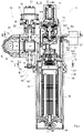
- figure 4 and 5 show the structure of the leakage protection fitting 10 in detail.
- a central channel 44 in the body 24 is aligned with the central channel 20.
- An annular channel 46 in the body 24 is aligned with the annular channel 22.
- the ball 28 of the ball valve 26 controls the flow through the central channel 44.
- figure 4 shows the ball valve 26 in the open position. Water can flow through the ball 28 therethrough.
- the ball 26 is positively connected to the spindle 30 .
- the spindle 30 is connected to the motor 32 .
- the control unit 34 receives signals from a turbine 50 which detects the volume flow through the leakage protection fitting downstream of the filter.
- the control unit 34 is provided with a processor with an evaluation program which determines whether unusual or undesired flow conditions are present. This can be a long-lasting, small current. This indicates micro-leakage. This can be a sudden, very large current. This indicates a broken pipe. When such or other undesirable or unusual flow conditions exist, alarm signals can be generated. Furthermore, a control signal can be sent to the motor 32, with which the ball valve 26 is closed.
- the control unit 34 has an Internet connection or a connection to another network, via which settings on the control unit 34 can be made. For example, a program on a PC with an internet connection or an application on a smartphone can be used for this purpose. The barrier 26 can be operated remotely in this way.
- the barrier 26 can also be actuated directly on the device 10 .
- a button 52 is provided on the controller 34 for this purpose. It goes without saying that another actuation element, such as a touch display, push button, switch or the like, can also be provided.
- actuation element such as a touch display, push button, switch or the like.
- the housing cup 38 is fastened to the outer socket 36.
- the housing cup 38 is made of plastic.
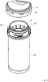
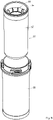
- a cylindrical replacement filter element 58 is provided, which is arranged concentrically in the housing cup 38 .
- the exchange element 58 consists of a water-impermeable inner cup 62 and a sieve element 60 arranged concentrically therein, which is held in the inner cup 62 by ribs 64 . This is in figure 18 and FIG. 19 can be seen clearly.
- figure 4 shows that the inner cup 62 protrudes upwards beyond the edge of the housing cup 38 into the outer socket 36 and is sealed there. So no water can get between the housing cup 38 and the inner cup 62 of the replacement filter element 58 .
- the water is filtered. Inside the screen element 60, the water flows upwards in the direction of the arrows 88 back into the remainder of the housing 24. If the screen element is dirty, it must be replaced and/or cleaned. For such maintenance, the housing cup 38 is removed.
- the housing socket 36 is provided with a plurality of spaced recesses 66 which extend in the circumferential direction at the lower edge of the socket 36 .
- the housing cup 38 has corresponding projections 68 spaced apart. The projections also extend in the circumferential direction on the upper edge of the housing cup 38 .
- the housing cup 38 is inserted into the socket 36 from below. The angle is chosen so that the projections 68 are guided through associated grooves 72 in the inner edge of the socket. this is in figure 9 to recognize.
- the housing cup 38 should only be removed from the rest of the housing 24 when it is ensured that the barrier 26 is properly closed.
- a lock for locking the bayonet catch is provided for this purpose.
- the lock is formed by a plate 74 in the present embodiment.
- the plate 74 has in one Direction 76 larger dimensions than in a second perpendicular direction 78 ( Fig.7 ).
- the short side of the plate is rounded.
- the plate 74 is connected to the ball 28 of the ball valve 26 via a spindle 80 .
- the housing 24 is provided with an opening.
- the spindle 80 is provided with seals and guided downwards from the ball 28 through the opening to the outside. This is in figure 4 clearly visible.
- the plate 74 is secured to the end of the spindle 80 by a small screw 82 from below. In operation, one end of the plate 74 protrudes through the recess 66 of the housing cup 38 into a rounded recess 84 in the projection 68. The radii of curvature of the short side of the plate 74 corresponds to the radius of curvature of the recess 84. This is shown in figure 4 and 7 illustrated.
- the plate 74 can be moved in and out of the recess 84.
- housing cup 38 engages recess 84, housing cup 38 is prevented from rotating. It cannot be removed.
- any other type of locking can be used, such as a pin.
- a magnetic detent or other electronically actuated detent can also be used.
- the attachment is not limited to bayonet locks.
- a conventional thread with a stop or a union nut or the like can also be used. The only important thing is that the lock is coupled with the barrier.
- a pressure relief valve At the lower end of the housing cup 38, a pressure relief valve, generally designated 90, is provided.
- the pressure relief valve 90 is in Figure 11 and Figure 12 shown again in detail. figure 11 shows the pressure relief valve 90 in the closed state and figure 12 in open condition. By opening the Pressure relief valve 90 allows water to be drained before housing cup 38 with replacement filter element 58 is removed for service.
- the housing cup 38 has an opening 92 at the lower end.
- a channel section 94 aligned with the opening is formed on the inside of the bottom of the inner cup 62 .
- the channel section 94 extends into the interior of the screen element 60.
- An outlet body 96 is screwed into the opening 92 in the bottom of the housing cup 38 with an external thread 98.
- the outlet body 96 is tubular in the upper area and extends coaxially through a channel 100 formed by the channel section 94 .
- Two sealing rings 102 seal the outlet body 96 against the inner wall of the channel section 94 .
- the tubular part of the outlet body 96 ends with a floor 102 .
- the duct 100 opens out into a duct 104 of small diameter.
- the channel 104 extends downwards and forms a housing-fixed valve seat of the pressure relief valve 90 at the lower end of the outlet body 96 with a seal 106.
- a depending ring 108 with an external thread is molded to the outlet body 96 around the valve seat.
- a rotary handle 110 is screwed onto the ring 108 .
- the rotary handle is provided with an axial center hole 112 .
- Ribs hold a valve closure body 114 with a transverse bore 116.
- Turning the rotary handle 110 moves the valve closure body 114 up and down. in the in figure 11
- the valve closing body 114 presses into the seal 106 with a projection.
- the valve is then closed and no water can run off downwards. in the in figure 12
- the position shown is the valve closing body a little further down. Water then flows past the valve closing body 114 in the direction of the arrows through the central bore 112 to the outside.
- the pressure relief valve 90 can withstand high pressures.
- the filtered water flows upwards from the filter in the direction of arrows 118 ( Fig.4 ).
- a backflow preventer 120 is arranged in the flow path.
- the backflow preventer 120 and the downstream arranged in the flow path turbine 50 are in the Figures 13 and 14 shown in detail.
- the housing 124 forms a housing inner connection piece 124 that is coaxial with the outer connection piece 36.
- An annular space 126 is formed between the connection piece 36 and the housing inner connection piece 124, which is in communication with the inlet 14 as described above.
- An insert 122 extends from the lower area of the housing inner socket 124 to the sieve element 60.
- the insert part 122 is tubular in sections. It has a downwardly projecting connecting piece 128 into which the upper edge of the sieve element 60 is inserted and sealed with a seal.
- the insert part 122 extends upward into the housing inner socket 124. This is figure 4 and 5 clearly visible.
- An outer threaded edge 130 of the insert part 122 which is L-shaped in cross section, is screwed into the housing inner socket 124 and sealed with a seal.
- the annular space 126 is thus separated from the annular space between the insert part 122 and the inner socket 124 of the housing.
- the insert part 122 forms an inwardly projecting edge 132. This is in figure 13 clearly visible.
- a cartridge-shaped turbine housing 134 sits on the edge, in which the turbine 50 and the backflow preventer 120 upstream of the turbine 50 are arranged.
- a turbine 50 has a starting resistance. In the case of particularly small flow volumes, which are typical for mini-leakage, the starting resistance is not overcome. The flow passes through the turbine 50 without setting it in motion. The backflow preventer 120 is therefore connected upstream, so that only flow volumes that are large enough to open the backflow preventer 120 are directed to the turbine. This ensures that flow volumes are reliably detected from a threshold value determined by the opening resistance of the backflow preventer.
- a bypass is provided for detecting smaller flows which do not readily overcome the starting resistance of the turbine 50 .
- the bypass includes an annular space 140 between the insert part 122 and the turbine housing 134 and a bypass channel 138 which connects the outer space 140 of the turbine housing to the area within the turbine housing 138 between the backflow preventer 120 and the turbine 50 .
- the bypass channel 138 is aligned in such a way that the flow reaches the turbine blade arranged in front of it with maximum force. As a result, the turbine 50 can be set in rotation even with smaller flow volumes.
- the intermediate space between the turbine housing 134 and the insert part 122 is widened between the annular space 140 and the bypass channel 138 .
- the bypass widens, so that an area with a triangular cross section 144 is formed.
- An elastomeric seal member 146 is loosely movable within flared area 144.
- An annular boss 148 on the exterior of turbine housing 134 retains elastomeric seal member 146 in area 144.
- the seal 144 If there is a pressure difference between the filter and the outlet, the seal 144 is pressed into the seat formed by the area 144 . No water can flow back through the bypass 140, 142 and 138 from the outlet.
- the seal 146 acts as a valve closing body for the bypass. In this way, when using a bypass, it is ensured that the turbine 50 rotates even with low flows and a signal is detected. At the same time, however, no water can flow back through the bypass if the filter consisting of the housing cup and filter element is to be removed, for example for maintenance purposes.
- the flow is measured in a known manner using the turbine 50 and a reed contact fixed to the housing.
- the signal from the reed contact is transmitted to the control and evaluation unit and processed there.
- the water flows through the pressure reducer 40 and is regulated to a desired pressure.
- the outlet area 156 of the pressure reducer 40 is connected to the annular channel 46 through which the water flows to the outlet 16 .
- the pressure reducer 40 is in the form of a pressure reducer insert which is inserted into a housing connector 152 which projects upwards.
- a floor 154 separates the outlet area 156 of the pressure reducer 40 from the downstream area of the turbine 50.
- the floor 154 is cup-shaped, with a vertical channel 158 being formed on the side, which in figure 4 is easy to see.
- the water flows via the channel 158 in the direction of the arrows to the inlet area of the pressure reducer 40.
- the pressure in the outlet area 156 of the pressure reducer 40 is recorded with a manometer 42 during operation.
- the pressure gauge 42 is seated on a lateral housing socket 174.
- the pressure is transmitted to the pressure gauge 42 via a horizontal connection 160 between the pressure gauge 42 and the outlet region 156.
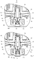
- Figure 15 and 16 show how the installer can see that the filter area within the housing cup 38 is depressurized, so that the housing cup 38 after loosening the Lock can be safely removed and serviced, for example.
- a vertical connection channel 162 is provided between the interior of the filter element 58 and the connection 160 between the pressure gauge 42 and the outlet area 156 of the pressure reducer 40 . This is in figure 4 illustrated.
- the upper end of the connecting channel 162 opens into the channel 160.
- the channel 160 between the outlet region 156 and the manometer 42 runs essentially horizontally and is closed with a plug 170 at the manometer-side end.
- a channel piece 172 connects the connecting channel 162 to the manometer.
- connection channel 162 which in the present exemplary embodiment is on the right in figure 4 runs in the vertical direction, a piston 164 with bone-like thickened ends 166 and 168 is performed.
- the piston is in Figure 15 and Figure 16 shown again in detail.
- the ends 166 and 168 are sealed against the connection channel 162 with gaskets.
- the inlet pressure also prevailing in the filter element 58 is higher than the outlet pressure of the pressure reducer 40 in the outlet area 156.
- the pressure acting on the piston 164 from below is consequently higher than the pressure acting on the piston 164 from above.
- the piston 164 is therefore in an up position during operation. This is in figure 15 shown.
- the upper enlarged end 166 of the piston 164 extends fully into the connection 160.
- the output pressure is therefore, as indicated by the arrows 176, in the area around the enlarged end 166, in the space around the tapered area 178 of the piston 164 and via the channel section 172 on the manometer.
- the lower thickened area 168 of the piston 164 is in the operating position in the area of a narrowing of the connecting channel 162, which also forms a stop. There is no connection to the connecting channel 162. This is blocked in this position of the piston 164.
- the outlet pressure is present on the manometer 42 in the operating position.
- top, bottom, bottom, right and “left” refer exclusively to the accompanying drawings. It is understood that claimed devices may also take a different orientation.
- containing and the term “comprising” mean that further components not mentioned can be provided.
- the term “essentially”, “predominantly” and “predominantly” includes all features that have a property or content in majority, i.e. more than all other components or properties of the feature mentioned, i.e. more than 50% for two components, for example.
Landscapes
- Engineering & Computer Science (AREA)
- Chemical Kinetics & Catalysis (AREA)
- General Engineering & Computer Science (AREA)
- Chemical & Material Sciences (AREA)
- Physics & Mathematics (AREA)
- General Physics & Mathematics (AREA)
- Health & Medical Sciences (AREA)
- Life Sciences & Earth Sciences (AREA)
- Hydrology & Water Resources (AREA)
- Public Health (AREA)
- Water Supply & Treatment (AREA)
- Mechanical Engineering (AREA)
- Fluid Mechanics (AREA)
- Details Of Valves (AREA)
- Safety Valves (AREA)
Applications Claiming Priority (1)
| Application Number | Priority Date | Filing Date | Title |
|---|---|---|---|
| DE202020106989.6U DE202020106989U1 (de) | 2020-12-04 | 2020-12-04 | Leckageschutz-Anordnung |
Publications (3)
| Publication Number | Publication Date |
|---|---|
| EP4008844A1 true EP4008844A1 (fr) | 2022-06-08 |
| EP4008844C0 EP4008844C0 (fr) | 2024-02-21 |
| EP4008844B1 EP4008844B1 (fr) | 2024-02-21 |
Family
ID=77543343
Family Applications (1)
| Application Number | Title | Priority Date | Filing Date |
|---|---|---|---|
| EP21193705.7A Active EP4008844B1 (fr) | 2020-12-04 | 2021-08-30 | Système de protection contre les fuites |
Country Status (2)
| Country | Link |
|---|---|
| EP (1) | EP4008844B1 (fr) |
| DE (1) | DE202020106989U1 (fr) |
Cited By (1)
| Publication number | Priority date | Publication date | Assignee | Title |
|---|---|---|---|---|
| WO2024033518A1 (fr) * | 2022-08-11 | 2024-02-15 | Bwt Holding Gmbh | Débitmètre et système d'installation doté d'un débitmètre |
Citations (7)
| Publication number | Priority date | Publication date | Assignee | Title |
|---|---|---|---|---|
| DE9200219U1 (de) * | 1992-01-10 | 1992-02-27 | Honeywell-Braukmann GmbH, 6950 Mosbach | Filter-Sicherheitskombination |
| DE102005000009A1 (de) | 2005-02-08 | 2006-08-17 | Hans Sasserath & Co. Kg | Filterarmatur mit Strömungszähler |
| DE102007026162A1 (de) | 2006-11-15 | 2008-05-29 | Hans Sasserath & Co. Kg | Absperrvorrichtung |
| DE202008003055U1 (de) | 2008-03-04 | 2008-09-18 | Hans Sasserath & Co Kg | Druckminderer-Filter Anordnung mit Leckageschutz |
| WO2014029699A1 (fr) | 2012-08-20 | 2014-02-27 | Hans Sasserath & Co Kg | Dispositif de protection contre les fuites |
| DE202014102880U1 (de) * | 2014-06-24 | 2015-09-25 | Hans Sasserath Gmbh & Co. Kg | Leckageschutzarmatur |
| EP3637216A1 (fr) * | 2018-10-10 | 2020-04-15 | Hans Sasserath GmbH & Co KG | Dispositif et procédé de régulation de la pression de flux de sortie d'une robinetterie d'eau |
-
2020
- 2020-12-04 DE DE202020106989.6U patent/DE202020106989U1/de active Active
-
2021
- 2021-08-30 EP EP21193705.7A patent/EP4008844B1/fr active Active
Patent Citations (7)
| Publication number | Priority date | Publication date | Assignee | Title |
|---|---|---|---|---|
| DE9200219U1 (de) * | 1992-01-10 | 1992-02-27 | Honeywell-Braukmann GmbH, 6950 Mosbach | Filter-Sicherheitskombination |
| DE102005000009A1 (de) | 2005-02-08 | 2006-08-17 | Hans Sasserath & Co. Kg | Filterarmatur mit Strömungszähler |
| DE102007026162A1 (de) | 2006-11-15 | 2008-05-29 | Hans Sasserath & Co. Kg | Absperrvorrichtung |
| DE202008003055U1 (de) | 2008-03-04 | 2008-09-18 | Hans Sasserath & Co Kg | Druckminderer-Filter Anordnung mit Leckageschutz |
| WO2014029699A1 (fr) | 2012-08-20 | 2014-02-27 | Hans Sasserath & Co Kg | Dispositif de protection contre les fuites |
| DE202014102880U1 (de) * | 2014-06-24 | 2015-09-25 | Hans Sasserath Gmbh & Co. Kg | Leckageschutzarmatur |
| EP3637216A1 (fr) * | 2018-10-10 | 2020-04-15 | Hans Sasserath GmbH & Co KG | Dispositif et procédé de régulation de la pression de flux de sortie d'une robinetterie d'eau |
Cited By (1)
| Publication number | Priority date | Publication date | Assignee | Title |
|---|---|---|---|---|
| WO2024033518A1 (fr) * | 2022-08-11 | 2024-02-15 | Bwt Holding Gmbh | Débitmètre et système d'installation doté d'un débitmètre |
Also Published As
| Publication number | Publication date |
|---|---|
| EP4008844C0 (fr) | 2024-02-21 |
| DE202020106989U1 (de) | 2022-03-07 |
| EP4008844B1 (fr) | 2024-02-21 |
Similar Documents
| Publication | Publication Date | Title |
|---|---|---|
| EP2098646A1 (fr) | Agencement réducteur de pression comportant un filtre avec protection anti-fuites | |
| DE3126507C2 (fr) | ||
| DE69612535T2 (de) | Vorgesteuertes Fluidumventil | |
| EP1681520A2 (fr) | vanne pour de fluide | |
| DE102007051433B3 (de) | Ventilanordnung für Warmwasserbereiter | |
| EP3637216B1 (fr) | Dispositif et procédé de régulation de la pression de flux de sortie d'une robinetterie d'eau | |
| DE102007026162A1 (de) | Absperrvorrichtung | |
| DE202014102880U1 (de) | Leckageschutzarmatur | |
| DE102019104413A1 (de) | Druckmindereranordnung | |
| EP3660620A1 (fr) | Soupape de réduction de pression | |
| DE202013102154U1 (de) | Anordnung zur Durchführung einer Hygienespülung in einer Wasserinstallation | |
| EP3406806B1 (fr) | Dispositif d'armature pourvu d'armature combinée et unité de traitement de l'eau et procédé de préparation de l'eau potable | |
| EP4008844B1 (fr) | Système de protection contre les fuites | |
| DE102005052385B4 (de) | Druckminderer | |
| DE202016103116U1 (de) | Filteranordnung | |
| DE202016101941U1 (de) | Druckmindereranordnung | |
| DE102012102701B3 (de) | Rohrtrenneranordnung | |
| EP0943901B1 (fr) | Raccord pour un dispositif de mesure de débit d'un liquide | |
| DE202015104028U1 (de) | Wasserleckageschutzvorrichtung für Gebäude | |
| DE102007005215B3 (de) | Systemtrenner | |
| DE10211533B4 (de) | Hahnblock | |
| DE202013104285U1 (de) | Systemtrenneranordnung | |
| DE202012101123U1 (de) | Rohrtrenneranordnung | |
| DE202019104544U1 (de) | Druckminderer-Anordnung | |
| EP2644789B1 (fr) | Ensemble modulaire d'un agencement de séparation de tuyaux |
Legal Events
| Date | Code | Title | Description |
|---|---|---|---|
| PUAI | Public reference made under article 153(3) epc to a published international application that has entered the european phase |
Free format text: ORIGINAL CODE: 0009012 |
|
| STAA | Information on the status of an ep patent application or granted ep patent |
Free format text: STATUS: THE APPLICATION HAS BEEN PUBLISHED |
|
| AK | Designated contracting states |
Kind code of ref document: A1 Designated state(s): AL AT BE BG CH CY CZ DE DK EE ES FI FR GB GR HR HU IE IS IT LI LT LU LV MC MK MT NL NO PL PT RO RS SE SI SK SM TR |
|
| STAA | Information on the status of an ep patent application or granted ep patent |
Free format text: STATUS: REQUEST FOR EXAMINATION WAS MADE |
|
| 17P | Request for examination filed |
Effective date: 20220829 |
|
| RBV | Designated contracting states (corrected) |
Designated state(s): AL AT BE BG CH CY CZ DE DK EE ES FI FR GB GR HR HU IE IS IT LI LT LU LV MC MK MT NL NO PL PT RO RS SE SI SK SM TR |
|
| GRAP | Despatch of communication of intention to grant a patent |
Free format text: ORIGINAL CODE: EPIDOSNIGR1 |
|
| STAA | Information on the status of an ep patent application or granted ep patent |
Free format text: STATUS: GRANT OF PATENT IS INTENDED |
|
| RIC1 | Information provided on ipc code assigned before grant |
Ipc: G01F 1/12 20060101ALI20231020BHEP Ipc: B01D 29/33 20060101ALI20231020BHEP Ipc: G01M 3/28 20060101ALI20231020BHEP Ipc: G01F 1/10 20060101ALI20231020BHEP Ipc: F16K 31/04 20060101ALI20231020BHEP Ipc: F16K 27/00 20060101ALI20231020BHEP Ipc: B01D 35/147 20060101ALI20231020BHEP Ipc: B01D 29/11 20060101ALI20231020BHEP Ipc: E03B 7/07 20060101AFI20231020BHEP |
|
| INTG | Intention to grant announced |
Effective date: 20231107 |
|
| GRAS | Grant fee paid |
Free format text: ORIGINAL CODE: EPIDOSNIGR3 |
|
| GRAA | (expected) grant |
Free format text: ORIGINAL CODE: 0009210 |
|
| STAA | Information on the status of an ep patent application or granted ep patent |
Free format text: STATUS: THE PATENT HAS BEEN GRANTED |
|
| AK | Designated contracting states |
Kind code of ref document: B1 Designated state(s): AL AT BE BG CH CY CZ DE DK EE ES FI FR GB GR HR HU IE IS IT LI LT LU LV MC MK MT NL NO PL PT RO RS SE SI SK SM TR |
|
| REG | Reference to a national code |
Ref country code: GB Ref legal event code: FG4D Free format text: NOT ENGLISH |
|
| REG | Reference to a national code |
Ref country code: CH Ref legal event code: EP |
|
| REG | Reference to a national code |
Ref country code: DE Ref legal event code: R096 Ref document number: 502021002742 Country of ref document: DE |
|
| REG | Reference to a national code |
Ref country code: IE Ref legal event code: FG4D Free format text: LANGUAGE OF EP DOCUMENT: GERMAN |
|
| U01 | Request for unitary effect filed |
Effective date: 20240221 |
|
| U07 | Unitary effect registered |
Designated state(s): AT BE BG DE DK EE FI FR IT LT LU LV MT NL PT SE SI Effective date: 20240301 |
|
| REG | Reference to a national code |
Ref country code: LT Ref legal event code: MG9D |
|
| PG25 | Lapsed in a contracting state [announced via postgrant information from national office to epo] |
Ref country code: IS Free format text: LAPSE BECAUSE OF FAILURE TO SUBMIT A TRANSLATION OF THE DESCRIPTION OR TO PAY THE FEE WITHIN THE PRESCRIBED TIME-LIMIT Effective date: 20240621 |
|
| PG25 | Lapsed in a contracting state [announced via postgrant information from national office to epo] |
Ref country code: GR Free format text: LAPSE BECAUSE OF FAILURE TO SUBMIT A TRANSLATION OF THE DESCRIPTION OR TO PAY THE FEE WITHIN THE PRESCRIBED TIME-LIMIT Effective date: 20240522 |
|
| PG25 | Lapsed in a contracting state [announced via postgrant information from national office to epo] |
Ref country code: RS Free format text: LAPSE BECAUSE OF FAILURE TO SUBMIT A TRANSLATION OF THE DESCRIPTION OR TO PAY THE FEE WITHIN THE PRESCRIBED TIME-LIMIT Effective date: 20240521 Ref country code: HR Free format text: LAPSE BECAUSE OF FAILURE TO SUBMIT A TRANSLATION OF THE DESCRIPTION OR TO PAY THE FEE WITHIN THE PRESCRIBED TIME-LIMIT Effective date: 20240221 |
|
| PG25 | Lapsed in a contracting state [announced via postgrant information from national office to epo] |
Ref country code: ES Free format text: LAPSE BECAUSE OF FAILURE TO SUBMIT A TRANSLATION OF THE DESCRIPTION OR TO PAY THE FEE WITHIN THE PRESCRIBED TIME-LIMIT Effective date: 20240221 |
|
| PG25 | Lapsed in a contracting state [announced via postgrant information from national office to epo] |
Ref country code: RS Free format text: LAPSE BECAUSE OF FAILURE TO SUBMIT A TRANSLATION OF THE DESCRIPTION OR TO PAY THE FEE WITHIN THE PRESCRIBED TIME-LIMIT Effective date: 20240521 Ref country code: NO Free format text: LAPSE BECAUSE OF FAILURE TO SUBMIT A TRANSLATION OF THE DESCRIPTION OR TO PAY THE FEE WITHIN THE PRESCRIBED TIME-LIMIT Effective date: 20240521 Ref country code: IS Free format text: LAPSE BECAUSE OF FAILURE TO SUBMIT A TRANSLATION OF THE DESCRIPTION OR TO PAY THE FEE WITHIN THE PRESCRIBED TIME-LIMIT Effective date: 20240621 Ref country code: HR Free format text: LAPSE BECAUSE OF FAILURE TO SUBMIT A TRANSLATION OF THE DESCRIPTION OR TO PAY THE FEE WITHIN THE PRESCRIBED TIME-LIMIT Effective date: 20240221 Ref country code: GR Free format text: LAPSE BECAUSE OF FAILURE TO SUBMIT A TRANSLATION OF THE DESCRIPTION OR TO PAY THE FEE WITHIN THE PRESCRIBED TIME-LIMIT Effective date: 20240522 Ref country code: ES Free format text: LAPSE BECAUSE OF FAILURE TO SUBMIT A TRANSLATION OF THE DESCRIPTION OR TO PAY THE FEE WITHIN THE PRESCRIBED TIME-LIMIT Effective date: 20240221 |
|
| PG25 | Lapsed in a contracting state [announced via postgrant information from national office to epo] |
Ref country code: PL Free format text: LAPSE BECAUSE OF FAILURE TO SUBMIT A TRANSLATION OF THE DESCRIPTION OR TO PAY THE FEE WITHIN THE PRESCRIBED TIME-LIMIT Effective date: 20240221 |
|
| U20 | Renewal fee for the european patent with unitary effect paid |
Year of fee payment: 4 Effective date: 20240716 |
|
| PG25 | Lapsed in a contracting state [announced via postgrant information from national office to epo] |
Ref country code: PL Free format text: LAPSE BECAUSE OF FAILURE TO SUBMIT A TRANSLATION OF THE DESCRIPTION OR TO PAY THE FEE WITHIN THE PRESCRIBED TIME-LIMIT Effective date: 20240221 |
|
| PG25 | Lapsed in a contracting state [announced via postgrant information from national office to epo] |
Ref country code: SM Free format text: LAPSE BECAUSE OF FAILURE TO SUBMIT A TRANSLATION OF THE DESCRIPTION OR TO PAY THE FEE WITHIN THE PRESCRIBED TIME-LIMIT Effective date: 20240221 |
|
| PG25 | Lapsed in a contracting state [announced via postgrant information from national office to epo] |
Ref country code: CZ Free format text: LAPSE BECAUSE OF FAILURE TO SUBMIT A TRANSLATION OF THE DESCRIPTION OR TO PAY THE FEE WITHIN THE PRESCRIBED TIME-LIMIT Effective date: 20240221 |
|
| PG25 | Lapsed in a contracting state [announced via postgrant information from national office to epo] |
Ref country code: SK Free format text: LAPSE BECAUSE OF FAILURE TO SUBMIT A TRANSLATION OF THE DESCRIPTION OR TO PAY THE FEE WITHIN THE PRESCRIBED TIME-LIMIT Effective date: 20240221 |
|
| PG25 | Lapsed in a contracting state [announced via postgrant information from national office to epo] |
Ref country code: SM Free format text: LAPSE BECAUSE OF FAILURE TO SUBMIT A TRANSLATION OF THE DESCRIPTION OR TO PAY THE FEE WITHIN THE PRESCRIBED TIME-LIMIT Effective date: 20240221 Ref country code: SK Free format text: LAPSE BECAUSE OF FAILURE TO SUBMIT A TRANSLATION OF THE DESCRIPTION OR TO PAY THE FEE WITHIN THE PRESCRIBED TIME-LIMIT Effective date: 20240221 Ref country code: RO Free format text: LAPSE BECAUSE OF FAILURE TO SUBMIT A TRANSLATION OF THE DESCRIPTION OR TO PAY THE FEE WITHIN THE PRESCRIBED TIME-LIMIT Effective date: 20240221 Ref country code: CZ Free format text: LAPSE BECAUSE OF FAILURE TO SUBMIT A TRANSLATION OF THE DESCRIPTION OR TO PAY THE FEE WITHIN THE PRESCRIBED TIME-LIMIT Effective date: 20240221 |
|
| REG | Reference to a national code |
Ref country code: DE Ref legal event code: R097 Ref document number: 502021002742 Country of ref document: DE |
|
| PLBE | No opposition filed within time limit |
Free format text: ORIGINAL CODE: 0009261 |
|
| STAA | Information on the status of an ep patent application or granted ep patent |
Free format text: STATUS: NO OPPOSITION FILED WITHIN TIME LIMIT |
|
| 26N | No opposition filed |
Effective date: 20241122 |
|
| PG25 | Lapsed in a contracting state [announced via postgrant information from national office to epo] |
Ref country code: MC Free format text: LAPSE BECAUSE OF FAILURE TO SUBMIT A TRANSLATION OF THE DESCRIPTION OR TO PAY THE FEE WITHIN THE PRESCRIBED TIME-LIMIT Effective date: 20240221 |
|
| PG25 | Lapsed in a contracting state [announced via postgrant information from national office to epo] |
Ref country code: IE Free format text: LAPSE BECAUSE OF NON-PAYMENT OF DUE FEES Effective date: 20240830 |
|
| U20 | Renewal fee for the european patent with unitary effect paid |
Year of fee payment: 5 Effective date: 20250724 |
|
| PGFP | Annual fee paid to national office [announced via postgrant information from national office to epo] |
Ref country code: CH Payment date: 20250901 Year of fee payment: 5 |
|
| PG25 | Lapsed in a contracting state [announced via postgrant information from national office to epo] |
Ref country code: CY Free format text: LAPSE BECAUSE OF FAILURE TO SUBMIT A TRANSLATION OF THE DESCRIPTION OR TO PAY THE FEE WITHIN THE PRESCRIBED TIME-LIMIT; INVALID AB INITIO Effective date: 20210830 |
|
| PG25 | Lapsed in a contracting state [announced via postgrant information from national office to epo] |
Ref country code: HU Free format text: LAPSE BECAUSE OF FAILURE TO SUBMIT A TRANSLATION OF THE DESCRIPTION OR TO PAY THE FEE WITHIN THE PRESCRIBED TIME-LIMIT; INVALID AB INITIO Effective date: 20210830 |