EP4008866B1 - Verfahren zur betriebssteuerung einer motorisierten antriebsvorrichtung eines schiebefensters für ein gebäude, entsprechendes fenster und entsprechende haustechnikanlage - Google Patents
Verfahren zur betriebssteuerung einer motorisierten antriebsvorrichtung eines schiebefensters für ein gebäude, entsprechendes fenster und entsprechende haustechnikanlage Download PDFInfo
- Publication number
- EP4008866B1 EP4008866B1 EP22152194.1A EP22152194A EP4008866B1 EP 4008866 B1 EP4008866 B1 EP 4008866B1 EP 22152194 A EP22152194 A EP 22152194A EP 4008866 B1 EP4008866 B1 EP 4008866B1
- Authority
- EP
- European Patent Office
- Prior art keywords
- relative
- frame
- opening
- sash
- fixed frame
- Prior art date
- Legal status (The legal status is an assumption and is not a legal conclusion. Google has not performed a legal analysis and makes no representation as to the accuracy of the status listed.)
- Active
Links
Images


Classifications
-
- E—FIXED CONSTRUCTIONS
- E05—LOCKS; KEYS; WINDOW OR DOOR FITTINGS; SAFES
- E05F—DEVICES FOR MOVING WINGS INTO OPEN OR CLOSED POSITION; CHECKS FOR WINGS; WING FITTINGS NOT OTHERWISE PROVIDED FOR, CONCERNED WITH THE FUNCTIONING OF THE WING
- E05F15/00—Power-operated mechanisms for wings
- E05F15/60—Power-operated mechanisms for wings using electrical actuators
- E05F15/603—Power-operated mechanisms for wings using electrical actuators using rotary electromotors
- E05F15/632—Power-operated mechanisms for wings using electrical actuators using rotary electromotors for horizontally-sliding wings
- E05F15/643—Power-operated mechanisms for wings using electrical actuators using rotary electromotors for horizontally-sliding wings operated by flexible elongated pulling elements, e.g. belts, chains or cables
-
- E—FIXED CONSTRUCTIONS
- E05—LOCKS; KEYS; WINDOW OR DOOR FITTINGS; SAFES
- E05B—LOCKS; ACCESSORIES THEREFOR; HANDCUFFS
- E05B65/00—Locks or fastenings for special use
- E05B65/08—Locks or fastenings for special use for sliding wings
- E05B65/087—Locks or fastenings for special use for sliding wings the bolts sliding parallel to the wings
- E05B65/0876—Locks or fastenings for special use for sliding wings the bolts sliding parallel to the wings cooperating with the slide guide, e.g. the rail
-
- E—FIXED CONSTRUCTIONS
- E05—LOCKS; KEYS; WINDOW OR DOOR FITTINGS; SAFES
- E05B—LOCKS; ACCESSORIES THEREFOR; HANDCUFFS
- E05B47/00—Operating or controlling locks or other fastening devices by electric or magnetic means
- E05B47/02—Movement of the bolt by electromagnetic means; Adaptation of locks, latches, or parts thereof, for movement of the bolt by electromagnetic means
- E05B47/026—Movement of the bolt by electromagnetic means; Adaptation of locks, latches, or parts thereof, for movement of the bolt by electromagnetic means the bolt moving rectilinearly
-
- E—FIXED CONSTRUCTIONS
- E05—LOCKS; KEYS; WINDOW OR DOOR FITTINGS; SAFES
- E05D—HINGES OR SUSPENSION DEVICES FOR DOORS, WINDOWS OR WINGS
- E05D13/00—Accessories for sliding or lifting wings, e.g. pulleys, safety catches
- E05D13/04—Fasteners specially adapted for holding sliding wings open
-
- E—FIXED CONSTRUCTIONS
- E05—LOCKS; KEYS; WINDOW OR DOOR FITTINGS; SAFES
- E05Y—INDEXING SCHEME ASSOCIATED WITH SUBCLASSES E05D AND E05F, RELATING TO CONSTRUCTION ELEMENTS, ELECTRIC CONTROL, POWER SUPPLY, POWER SIGNAL OR TRANSMISSION, USER INTERFACES, MOUNTING OR COUPLING, DETAILS, ACCESSORIES, AUXILIARY OPERATIONS NOT OTHERWISE PROVIDED FOR, APPLICATION THEREOF
- E05Y2201/00—Constructional elements; Accessories therefor
- E05Y2201/20—Brakes; Disengaging means; Holders; Stops; Valves; Accessories therefor
- E05Y2201/218—Holders
- E05Y2201/22—Locks
-
- E—FIXED CONSTRUCTIONS
- E05—LOCKS; KEYS; WINDOW OR DOOR FITTINGS; SAFES
- E05Y—INDEXING SCHEME ASSOCIATED WITH SUBCLASSES E05D AND E05F, RELATING TO CONSTRUCTION ELEMENTS, ELECTRIC CONTROL, POWER SUPPLY, POWER SIGNAL OR TRANSMISSION, USER INTERFACES, MOUNTING OR COUPLING, DETAILS, ACCESSORIES, AUXILIARY OPERATIONS NOT OTHERWISE PROVIDED FOR, APPLICATION THEREOF
- E05Y2201/00—Constructional elements; Accessories therefor
- E05Y2201/20—Brakes; Disengaging means; Holders; Stops; Valves; Accessories therefor
- E05Y2201/23—Actuation thereof
- E05Y2201/246—Actuation thereof by auxiliary motors, magnets, springs or weights
-
- E—FIXED CONSTRUCTIONS
- E05—LOCKS; KEYS; WINDOW OR DOOR FITTINGS; SAFES
- E05Y—INDEXING SCHEME ASSOCIATED WITH SUBCLASSES E05D AND E05F, RELATING TO CONSTRUCTION ELEMENTS, ELECTRIC CONTROL, POWER SUPPLY, POWER SIGNAL OR TRANSMISSION, USER INTERFACES, MOUNTING OR COUPLING, DETAILS, ACCESSORIES, AUXILIARY OPERATIONS NOT OTHERWISE PROVIDED FOR, APPLICATION THEREOF
- E05Y2201/00—Constructional elements; Accessories therefor
- E05Y2201/40—Motors; Magnets; Springs; Weights; Accessories therefor
- E05Y2201/43—Motors
- E05Y2201/434—Electromotors; Details thereof
-
- E—FIXED CONSTRUCTIONS
- E05—LOCKS; KEYS; WINDOW OR DOOR FITTINGS; SAFES
- E05Y—INDEXING SCHEME ASSOCIATED WITH SUBCLASSES E05D AND E05F, RELATING TO CONSTRUCTION ELEMENTS, ELECTRIC CONTROL, POWER SUPPLY, POWER SIGNAL OR TRANSMISSION, USER INTERFACES, MOUNTING OR COUPLING, DETAILS, ACCESSORIES, AUXILIARY OPERATIONS NOT OTHERWISE PROVIDED FOR, APPLICATION THEREOF
- E05Y2800/00—Details, accessories and auxiliary operations not otherwise provided for
- E05Y2800/40—Physical or chemical protection
- E05Y2800/424—Physical or chemical protection against unintended use, e.g. protection against vandalism or sabotage
- E05Y2800/426—Physical or chemical protection against unintended use, e.g. protection against vandalism or sabotage against unauthorised use, e.g. keys
-
- E—FIXED CONSTRUCTIONS
- E05—LOCKS; KEYS; WINDOW OR DOOR FITTINGS; SAFES
- E05Y—INDEXING SCHEME ASSOCIATED WITH SUBCLASSES E05D AND E05F, RELATING TO CONSTRUCTION ELEMENTS, ELECTRIC CONTROL, POWER SUPPLY, POWER SIGNAL OR TRANSMISSION, USER INTERFACES, MOUNTING OR COUPLING, DETAILS, ACCESSORIES, AUXILIARY OPERATIONS NOT OTHERWISE PROVIDED FOR, APPLICATION THEREOF
- E05Y2800/00—Details, accessories and auxiliary operations not otherwise provided for
- E05Y2800/74—Specific positions
- E05Y2800/75—Specific positions intermediate
-
- E—FIXED CONSTRUCTIONS
- E05—LOCKS; KEYS; WINDOW OR DOOR FITTINGS; SAFES
- E05Y—INDEXING SCHEME ASSOCIATED WITH SUBCLASSES E05D AND E05F, RELATING TO CONSTRUCTION ELEMENTS, ELECTRIC CONTROL, POWER SUPPLY, POWER SIGNAL OR TRANSMISSION, USER INTERFACES, MOUNTING OR COUPLING, DETAILS, ACCESSORIES, AUXILIARY OPERATIONS NOT OTHERWISE PROVIDED FOR, APPLICATION THEREOF
- E05Y2900/00—Application of doors, windows, wings or fittings thereof
- E05Y2900/10—Application of doors, windows, wings or fittings thereof for buildings or parts thereof
- E05Y2900/13—Type of wing
- E05Y2900/148—Windows
Definitions
- the present invention relates to a method for controlling the operation of a motorized drive device for a sliding window for a building, a sliding window for a building associated with such a control method, as well as a home automation installation comprising such a sliding window.
- the present invention relates to the field of windows comprising a motorized drive device setting in motion an opening relative to a fixed frame following a sliding movement, between at least a first position and at least a second position.
- a motorized drive device of such a window comprises an electromechanical actuator.
- the locking device comprises a first subassembly and a second subassembly.
- the first subassembly is fixed to the fixed frame.
- the second subassembly is fixed to the opening leaf.
- the second subassembly comprises a finger movable about an axis of rotation and an elastic return element.
- the elastic return element is configured to bring the movable finger to a rest position.
- the movable finger is configured to cooperate with the first subassembly, during a movement of the opening leaf relative to the fixed frame, so as to be able to lock the opening leaf relative to the fixed frame.
- the first subassembly comprises a rack.
- the movable finger of the second subassembly is configured to cooperate with notches of the rack of the first subassembly.
- the locking device is configured to be able to lock the sash relative to the frame in an open position, a closed position, and a locked ajar position.
- the locked ajar position is disposed between the open position and the closed position of the sash relative to the frame.
- the unlocking of the opening relative to the fixed frame can only be carried out manually by pulling on a chain connected to the movable finger.
- the present invention aims to solve the aforementioned drawbacks.
- the present invention relates to a method for controlling the operation of a motorized drive device for a sliding window for a building, as defined in claim 1.
- the present invention also relates to a sliding window for a building, as defined in claim 8, as well as a home automation installation, as defined in claim 10.
- the first locking device makes it possible to lock the opening relative to the fixed frame in the locked half-open position by means of the motorized drive device.
- the first locking device makes it possible to ensure the ventilation of the building in a secure manner by a half-opening of the opening relative to the fixed frame, in particular by means of simple parts.
- the unlocking of the opening relative to the fixed frame in connection with the first locking device is implemented by means of the motorized drive device configured to generate a movement of the opening relative to the fixed frame passing through the closed and locked position of the opening relative to the fixed frame, by means of the second locking device.
- the electronic control unit of the motorized drive device makes it possible to control the movement of the opening leaf relative to the fixed frame in order to lock the opening leaf relative to the fixed frame in the locked half-open position and to unlock the opening leaf relative to the fixed frame from the locked half-open position.
- the first locking device thus makes it possible to prohibit, or at least delay, an attempted intrusion by an individual.
- Sliding window 2 can also be called sliding bay window.
- the present invention applies to sliding windows and sliding French windows, whether or not equipped with transparent glazing.
- Window 2 comprises at least one opening 3a, 3b and a fixed frame 4.
- window 2 comprises a first opening 3a and a second opening 3b.
- the window 2 also comprises a motorized drive device 5 configured to slide an opening 3a relative to the fixed frame 4.
- the motorized drive device 5 is configured to slide only one of the first and second openings 3a, 3b relative to the fixed frame 4, in particular the first opening 3a.
- the second opening 3b is movable manually, in particular by the action of a user exerting a force on a handle, not shown, of the second opening 3b.
- the second opening 3b is fixed.
- the number of window openings is not limited and may be different, in particular equal to three.
- Each opening 3a, 3b comprises a frame 15.
- Each opening 3a, 3b may also comprise at least one window 16 arranged in the frame 15.
- the number of windows in the opening is not limited and may be different, in particular equal to two or more.
- the frame 15 of each opening 3a, 3b comprises an upper crosspiece 15a, a lower crosspiece, not shown, and first and second lateral uprights 15c, in the assembled configuration of the window 2 relative to the building, as illustrated in Figures 1 to 3 .
- the first side post 15c of the frame 15 of the first opening 3a is the side post 15c located on the right of the first opening 3a. Furthermore, the second side post 15c of the frame 15 of the first opening 3a is the side post 15c located on the left of the first opening 3a.
- the first side upright 15c of the frame 15 of the first opening 3a is opposite the second side upright 15c of the frame 15 of the first opening 3a.
- first side post 15c of the frame 15 of the second opening 3b is the side post 15c located on the right of the second opening 3b.
- second side post 15c of the frame 15 of the second opening 3b is the side post 15c located on the left of the second opening 3b.
- the first side upright 15c of the frame 15 of the second opening 3b is opposite the second side upright 15c of the frame 15 of the second opening 3b.
- the sleeping frame 4 comprises an upper crosspiece 4a, a lower crosspiece, not shown, and first and second side uprights 4c, in the configuration assembly of window 2 relative to the building, as shown in Figures 1 to 3 .
- the first side upright 4c of the sleeping frame 4 is the side upright 4c located on the right of the sleeping frame 4. Furthermore, the second side upright 4c of the sleeping frame 4 is the side upright 4c located on the left of the sleeping frame 4.
- the first side upright 4c of the sleeping frame 4 is opposite the second side upright 4c of the sleeping frame 4.
- the upper crosspiece 4a, the lower crosspiece and the two side uprights 4c of the dormant frame 4 respectively have an inner face and at least one outer face.
- the inner faces of the upper crosspiece 4a, of the lower crosspiece and of the two side uprights 4c of the fixed frame 4 are oriented towards the inside of the window 2 and, in particular, towards an outer edge of the frame 15 of each opening 3a, 3b.
- the outer faces of the upper crosspiece 4a, the lower crosspiece and the two side uprights 4c of the fixed frame 4 are oriented towards the outside of the window 2.
- the window 2 also includes a fitting system, not shown, arranged between the fixed frame 4 and each opening leaf 3a, 3b.
- the fitting system of the window 2 is not shown in the Figures 1 to 3 , so as to make them easier to read.
- the fitting system of the sliding window 2 allows each opening 3a, 3b to slide relative to the fixed frame 4 in a sliding direction D, in the horizontal example, in the assembled configuration of the window 2 relative to the building, as illustrated in Figures 1 to 3 .
- the hardware system comprises a cremone bolt and elements for locking the first opening 3a relative to the fixed frame 4.
- the fitting system is mounted along the first side upright 15c of the frame 15 of the first opening 3a.
- the cremone bolt is arranged inside the first side upright 15c of the frame 15 of the first opening 3a.
- the cremone bolt can also be arranged partly inside the upper crosspiece 15a or the lower crosspiece of the frame 15 of the first opening 3a.
- the cremone bolt comprises at least one rod.
- the cremone bolt also comprises a body.
- the body of the cremone bolt is fixed relative to the first lateral upright 15c of the frame 15 of the first opening 3a.
- the rod is configured to move relative to the body of the cremone bolt.
- the rod is made of several parts connected together, in particular by means of holding elements.
- the movement of the rod of the cremone bolt is implemented along the first lateral upright 15c of the frame 15 of the first opening 3a, in particular in a vertical direction, in the assembled configuration of the window 2 relative to the building.
- the rod of the cremone bolt comprises at least one hook forming a locking element.
- the fixed frame 4, in particular the first lateral upright 4c of the fixed frame 4, comprises at least one striker, not shown.
- Each hook of the rod is configured to cooperate with the aforementioned striker of the fixed frame 4.
- the hooks of the rod, as well as the latches provided in the frame 4, form at least in part the locking elements of the fitting system.
- the first opening 3a is in a so-called locked closed position, which is both closed and locked relative to the frame 4.
- the first opening 3a is in an unlocked position relative to the fixed frame 4, which can also be closed or open.
- the upper crosspiece 4a of the fixed frame 4 comprises a sliding rail 11a to allow sliding of the first opening 3a and a sliding rail, not shown, to allow sliding of the second opening 3b.
- the lower crosspiece of the fixed frame 4 also comprises two sliding rails, respectively for the first opening 3a and the second opening 3b.
- each of the upper 4a and lower crosspieces of the fixed frame 4 comprises a first sliding rail 11a or equivalent for the first opening 3a and a second sliding rail or equivalent for the second opening 3b.
- first and second openings 3a, 3b are configured to move respectively along the first and second sliding rails 11a and the like.
- first and second sliding rails 11a or equivalent are arranged parallel to each other. Furthermore, the first and second sliding rails 11a or equivalent are offset relative to each other according to the thickness of the dormant frame 4.
- the window 2 comprises sliding elements, not shown, allowing the movement of each opening 3a, 3b relative to the fixed frame 4.
- the sliding elements are arranged inside the first and second sliding rails of the lower crosspiece.
- the sliding elements comprise rollers arranged under the first and second openings 3a, 3b.
- the rollers are configured to roll inside the first and second sliding rails of the lower crosspiece.
- a partial or maximum sliding opening position of each opening 3a, 3b relative to the fixed frame 4 corresponds to a ventilation position of the building.
- the motorized drive device 5 makes it possible to automatically move the first opening leaf 3a by sliding relative to the fixed frame 4, in particular between the maximum opening position by sliding the first opening leaf 3a relative to the fixed frame 4 and the closed position of the first opening leaf 3a relative to the fixed frame 4.
- the motorized drive device 5 comprises an electromechanical actuator 6.
- the electromechanical actuator 6 comprises an electric motor 7.
- the electromechanical actuator 6 also comprises an output shaft 8, which is rotatable about an axis of rotation X.
- the axis of rotation X is parallel to the sliding direction D of the first opening 3a relative to the fixed frame 4 and, in the present case, of the second opening 3b relative to the fixed frame 4.
- the electric motor 7 of the electromechanical actuator 6 is of the variable speed type.
- the electric motor 7 is configured to drive the output shaft 8 in rotation according to at least a first rotation speed setpoint and a second rotation speed setpoint, such that the movement of the first opening 3a relative to the fixed frame 4 is implemented either at a first speed or at a second speed, different from the first speed.
- the electric motor 7 is of the brushless type with electronic commutation, also called “BLDC” (acronym for the Anglo-Saxon term BrushLess Direct Current) or “synchronous with permanent magnets”.
- BLDC brushless type with electronic commutation
- the electromechanical actuator 6 is of the reversible type.
- the electromechanical actuator 6 is controlled by an electronic control unit 10 belonging to the motorized drive device 5.
- an electronic control unit 10 makes it possible to determine the position of the first opening 3a by relative to the frame 4, as well as to trigger movements of the first opening 3a relative to the frame 4 by means of the electromechanical actuator 6, autonomously.
- the electronic control unit 10 associated with the electromechanical actuator 6 is configured to detect a movement of the first opening leaf 3a relative to the fixed frame 4 implemented manually and, more particularly, by an element external to the electromechanical actuator 6 acting on the first opening leaf 3a.
- the electromechanical actuator 6 is devoid of a brake, in particular to allow the electromechanical actuator 6 to be reversible.
- the electromechanical actuator 6 is arranged on a part fixed relative to the window 2, in particular relative to the fixed frame 4.
- the electromechanical actuator 6 may also comprise a reduction device, in particular with gears, not shown.
- the electromechanical actuator 6 may also comprise an end-of-travel and/or obstacle detection device, not shown. This detection device may be mechanical or electronic.
- the electric motor 7 and, optionally, the reduction device are arranged inside a casing 17 of the electromechanical actuator 6.
- the electromechanical actuator 6 is of the tubular type.
- the motorized drive device 5 also comprises a flexible element 9.
- the flexible element 9 is driven in movement by the electromechanical actuator 6.
- the flexible element 9 is configured to drive the first opening leaf 3a in movement relative to the fixed frame 4, when the electromechanical actuator 6 is electrically activated.
- the flexible element 9 comprises a first strand 9a and a second strand 9b.
- the flexible element 9 may be of circular section.
- the section of the flexible element is not limiting and may be different, in particular square, rectangular or even oval.
- the flexible element 9 is a cable or a cord.
- the material of the flexible element is not limiting and may be different. In particular, it may be steel.
- the motorized drive device 5 also comprises a drive arm 18.
- the drive arm 18 is, on the one hand, fixed to the first opening 3a and, on the other hand, connected to the flexible element 9.
- the drive arm 18 is configured to secure the flexible element 9 to the first opening 3a.
- the drive arm 18 is connected to the flexible element 9 by means of a shuttle 45.
- the shuttle 45 is fixed to the flexible element 9, in particular to the second strand 9b of the flexible element 9, by means of fixing elements, not shown.
- the fixing elements of the flexible element 9, in particular of the second strand 9b of the flexible element 9, on the shuttle 45 can be of the cable clamp type.
- these fixing elements are screws, for example two in number, configured to be screwed respectively into a screw hole of the shuttle 45, so as to fix the flexible element 9, in particular the second strand 9b of the flexible element 9, by wedging between the head of the screws and a surface of the shuttle 45.
- the drive arm 18 is fixed directly to the first opening 3a.
- the drive arm 18 is connected, on the one hand, to the frame 15 of the first opening 3a and, more particularly, to the first lateral upright 15c of the frame 15 of the first opening 3a and, on the other hand, to the flexible element 9.
- the drive arm 18 is fixed, therefore immobile, relative to the frame 15 of the first opening 3a.
- connection between the drive arm 18 and the frame 15 of the first opening 3a is simplified and makes it possible to minimize the costs of obtaining the window 2.
- the drive arm 18 is arranged in the upper part of the first lateral upright 15c of the frame 15 of the first opening 3a.
- the drive arm 18 is configured to hook onto the flexible element 9 arranged above the sleeping frame 4 and, more particularly, arranged inside a crosspiece 47.
- the drive arm 18 is fixed on an external face of the first lateral upright 15c of the frame 15 of the first opening 3a.
- the drive arm 18 is fixed on a face of the first side upright 15c of the frame 15 of the first opening 3a oriented towards the outside of the window 2, in other words visible to the user.
- the drive arm 18 is assembled with the first opening 3a on the inner side of the frame 15 of the first opening 3a, in the assembled configuration of the window 2 relative to the building.
- the inner side of the frame 15 of the first opening 3a is oriented towards the interior of the building, in the assembled configuration of the window 2 relative to the building.
- the flexible element 9 is connected to the drive arm 18, regardless of the state of the locking elements of the fitting system, i.e. both in the locked state and in the unlocked state of the first opening 3a relative to the fixed frame 4.
- the flexible element 9 is connected to the drive arm 18 permanently, in the assembled configuration of the motorized drive device 5 on the window 2.
- connection between the flexible element 9 and the drive arm 18 is simplified and makes it possible to minimize the costs of obtaining the window 2.
- the drive arm 18 is fixed to the first lateral upright 15c of the frame 15 of the first opening leaf 3a, configured to cooperate with the first lateral upright 4c of the fixed frame 4, when reaching the closed position of the first opening leaf 3a relative to the fixed frame 4.
- the drive arm 18 is fixed to the first lateral upright 15c of the frame 15 of the first opening 3a by means of fixing elements, not shown, in particular removable by means of a tool.
- the fixing elements of the drive arm 18 on the first opening 3a are screw fixing elements.
- the type of fastening elements of the drive arm on the first opening is not limiting and may be different. In particular, they may be elastic snap-fastening fastening elements.
- the drive arm 18 is fixed to the frame 15 of the first opening leaf 3a, following the installation of the first opening leaf 3a inside the fixed frame 4 and, in the present case, also of the second opening leaf 3b inside the fixed frame 4, installation during which the adjustments of the fitting system and the sliding elements are implemented.
- the adjustments of the fitting system and the sliding elements can be implemented manually and conventionally, as for a window without the motorized drive device 5.
- the drive arm 18 is fixed to the frame 15 of the first opening 3a, following the electrical connection of the electromechanical actuator 6, either to a mains power supply network or to a battery.
- the window 2 comprises a covering element.
- the covering element is configured to cover at least the drive arm 18.
- the trim element is configured to cover only the drive arm 18.
- the cladding element is configured to cover the drive arm 18 as well as part or all of the first lateral upright 15c of the frame 15 of the first opening 3a, in particular depending on the height of the frame 15, in the assembled configuration of the window 2 relative to the building.
- the cladding element is fixed relative to the first opening 3a by means of fixing elements, following the assembly of the drive arm 18 on the frame 15 of the first opening 3a.
- the fixing elements of the covering element are configured to cooperate with the drive arm 18 and/or with the first lateral upright 15c of the frame 15 of the first opening 3a.
- the fixing elements of the cladding element relative to the first opening 3a may be, in particular, fixing elements by elastic snap-fastening or by screwing.
- the crosspiece 47 comprises a slide 36. Furthermore, the shuttle 45 is configured to slide inside the slide 36 of the crosspiece 47.
- the motorized drive device 5 comprises a winding pulley 19 of the flexible element 9.
- the winding pulley 19 is driven in rotation by the output shaft 8 of the electromechanical actuator 6.
- a first end of the first strand 9a of the flexible element 9 is connected to a first part of the winding pulley 19.
- a first end of the second strand 9b of the flexible element 9 is connected to a second part of the winding pulley 19.
- first end of each of the first and second strands 9a, 9b of the flexible element 9 is attached respectively to the first part or to the second part of the winding pulley 19 by means of fixing elements 46.
- each of the first and second strands 9a, 9b of the flexible element 9 is respectively fixed directly to the first part or to the second part of the winding pulley 19.
- the fixing elements 46 of the end of each of the first and second strands 9a, 9b of the flexible element 9 are cable clamp type elements.
- these fixing elements 46 are screws, in particular of the self-tapping type, screwing into the winding pulley 19, so as to fix the first and second strands 9a, 9b of the flexible element 9 by wedging between the head of the screws and the winding surface of the flexible element 9 of the winding pulley 19.
- the direction of winding, respectively of unwinding, of the first strand 9a of the flexible element 9 around the first part of the winding pulley 19 is opposite to the direction of winding, respectively of unwinding, of the second strand 9b of the flexible element 9 around the second part of the winding pulley 19.
- the first strand 9a of the flexible element 9 unwinds around the first part of the winding pulley 19, while the second strand 9b of the flexible element 9 winds around the second part of the winding pulley 19.
- the second sliding direction of the first opening 3a relative to the fixed frame 4 is opposite to the first sliding direction.
- the direction of sliding of the first opening 3a relative to the fixed frame 4 is determined as a function of the direction of rotation of the output shaft 8 of the electromechanical actuator 6. Furthermore, the direction of rotation of the winding pulley 19 is determined by the direction of rotation of the output shaft 8 of the electromechanical actuator 6.
- the direction of rotation of the first strand 9a and the second strand 9b of the flexible element 9 around the first and second parts of the winding pulley 19 is a function of the direction of rotation of the output shaft 8 of the electromagnetic actuator 6.
- the direction of rotation of the winding pulley 19 is identical to the direction of rotation of the output shaft 8 of the electromechanical actuator 6.
- Control means of the electromechanical actuator 6 make it possible to control the sliding movement of the first opening 3a relative to the fixed frame 4.
- These control means comprise at least the electronic control unit 10.
- the electronic control unit 10 is configured to operate the electric motor 7 of the electromechanical actuator 6 and, in particular, to enable the supply of electrical energy to the electric motor 7.
- the electronic control unit 10 controls, in particular, the electric motor 7, so as to open or close by sliding the first opening 3a relative to the fixed frame 4.
- the window 2 comprises the electronic control unit 10. More particularly, the electronic control unit 10 is integrated into the motorized drive device 5.
- the motorized drive device 5 is a subassembly pre-assembled before mounting, in the example on the crosspiece 47, which comprises at least the electromechanical actuator 6, the winding pulley 19, the flexible element 9 and the electronic control unit 10.
- the motorized drive device 5 is controlled by a control unit.
- the control unit may be, for example, a local control unit 12.
- the local control unit 12 can be connected by wired or wireless connection to a central control unit 13.
- the central control unit 13 controls the local control unit 12, as well as other similar local control units distributed throughout the building.
- the electronic control unit 10 also comprises a module for receiving orders, in particular radioelectric orders emitted by an order transmitter, such as the local control unit 12 or the central control unit 13, these orders being intended to control the motorized drive device 5.
- the order receiving module can also allow the reception of orders transmitted by wired means.
- the electronic control unit 10, the local control unit 12 and/or the central control unit 13 may be in communication with one or more sensors configured to determine, for example, a temperature, a humidity, a wind speed, a measurement of an indoor or outdoor air quality parameter or even a presence.
- the central control unit 13 can also be in communication with a server 14, so as to control the electromechanical actuator 6 according to data made available remotely via a communication network, in particular an internet network which can be connected to the server 14.
- a communication network in particular an internet network which can be connected to the server 14.
- the electronic control unit 10 can be controlled from the local control unit 12.
- the local control unit 12 is provided with a control keyboard.
- the control keyboard of the local control unit 12 comprises selection elements and, optionally, display elements.
- the selection elements may be push buttons or sensitive keys
- the display elements may be light-emitting diodes, an LCD (acronym for the English expression “Liquid Crystal Display”) or TFT (acronym for the English expression “Thin Film Transistor”) display.
- the selection and display elements may also be produced by means of a touch screen.
- the local control unit 12 may be a fixed or nomadic control point.
- a fixed control point corresponds to a control box intended to be fixed on a facade of a wall of the building, on a face of the frame 15 of the first opening 3a of the window 2 or on one side of the fixed frame 4 of window 2.
- a portable control point corresponds to a remote control.
- the local control unit 12 allows the electronic control unit 10 to be directly controlled according to a selection made by the user.
- the local control unit 12 allows the user to intervene directly on the electromechanical actuator 6 of the motorized drive device 5 via the electronic control unit 10 associated with this motorized drive device 5, or to intervene indirectly on the electromechanical actuator 6 of the motorized drive device 5 via the central control unit 13.
- the motorized drive device 5, in particular the electronic control unit 10, is preferably configured to execute control commands for closing by sliding as well as opening by sliding of the first opening leaf 3a relative to the fixed frame 4, these control commands being able to be issued, in particular, by the local control unit 12 or by the central control unit 13.
- the electronic control unit 10 is thus able to operate the electromechanical actuator 6 of the motorized drive device 5 and, in particular, to enable the supply of electrical energy to the electromechanical actuator 6.
- the electronic control unit 10 is arranged inside the casing 17 of the electromechanical actuator 6.
- the control means of the electromechanical actuator 6 comprise hardware and/or software means.
- the hardware means may include at least one microcontroller.
- the local control unit 12 comprises a sensor measuring at least one parameter of the environment inside the building and integrated into this unit.
- the local control unit 12 can communicate with the central control unit 13, and the central control unit 13 can control the electronic control unit 10 associated with the motorized drive device 5 based on data from the sensor measuring the parameter of the environment inside the building.
- the local control unit 12 can directly control the electronic control unit 10 associated with the motorized drive device 5 based on data coming from the sensor measuring the parameter of the environment inside the building.
- an environmental parameter to inside the building measured by the sensor integrated into the local control unit 12 is the humidity, temperature, carbon dioxide level or the level of a volatile organic compound in the air.
- the activation of the local control unit 12 by the user takes priority over the activation of the central control unit 13, so as to control the closing and opening by sliding of the first opening leaf 3a relative to the fixed frame 4.
- the activation of the local control unit 12 directly controls the electronic control unit 10 associated with the motorized drive device 5 according to a selection made by the user, possibly inhibiting a control order that can be issued by the central control unit 13 or ignoring a value measured by a sensor measuring at least one parameter of the environment inside the building or outside the building, or a presence detection signal inside the building.
- the motorized drive device 5 can be controlled by the user, for example by receiving a control command corresponding to pressing a selection element of the local control unit 12, such as a remote control or a fixed control point.
- the motorized drive device 5 can also be controlled automatically, for example by receiving a control command corresponding to at least one signal from at least one sensor and/or a signal from a clock.
- the sensor and/or the clock can be integrated into the local control unit 12 or the central control unit 13.
- the motorized drive device 5 makes it possible to automatically move the first opening leaf 3a by sliding relative to the fixed frame 4 to a predetermined position, between the closed position and the maximum opening position.
- the sliding movement of the first opening leaf 3a relative to the fixed frame 4 to the predetermined position, in particular partial opening, is implemented following the reception of a control order issued by the local control unit 12, the central control unit 13 or a sensor.
- a sliding movement of the first opening 3 relative to the fixed frame 4 in the sliding direction D is implemented by supplying electrical energy to the electromechanical actuator 6, so as to unwind or wind the first and second strands 9a, 9b of the flexible element 9 around the first and second parts of the winding pulley 19.
- the unwinding or winding of the first and second strands 9a, 9b of the flexible element 9 around the first and second parts of the winding pulley 19 is controlled by the electrical energy supply of the electromechanical actuator 6.
- the electrical energy supply to the electromechanical actuator 6 is controlled by a control order received by the electronic control unit 10 coming from the local control unit 12, from the central control unit 13 or from a sensor.
- the motorized drive device 5, in particular the electromechanical actuator 6, is supplied with electrical energy from a power supply network.
- the electromechanical actuator 6 comprises an electrical power supply cable, not shown, allowing it to be supplied with electrical energy from the mains power supply network.
- the motorized drive device 5, in particular the electromechanical actuator 6, is supplied with electrical energy by means of a battery, not shown.
- the battery can be recharged, for example, by a photovoltaic panel or any other energy recovery system, in particular, of the thermal type.
- the winding pulley 19 and the output shaft 8 of the electromechanical actuator 6 have the same axis of rotation, namely the axis of rotation X.
- the axis of rotation of the winding pulley 19 coincides with the axis of rotation of the output shaft 8 of the electromechanical actuator 6.
- the winding pulley 19 is arranged in the extension of the output shaft 8 of the electromechanical actuator 6 and is driven in rotation about the same axis of rotation X as the output shaft 8 of the electromechanical actuator 6.
- the flexible element 9 forms a loop, called open, between the first end of the first strand 9a, connected to the first part of the winding pulley 19, and the first end of the second strand 9b, connected to the second part of the winding pulley 19.
- first and second strands 9a, 9b of the flexible element 9 are connected to the winding pulley 19 and separated at the first and second parts thereof.
- the electromechanical actuator 6 is fixed to the crosspiece 47 by means of fixing elements 28.
- winding pulley 19 is held on the crosspiece 47 by means of these same fixing elements 28.
- the fixing elements 28 of the electromechanical actuator 6 on the crosspiece 47 comprise supports, in particular fixing brackets.
- these supports are fixed to the crosspiece 47 of the fixed frame 4 by screwing.
- each support of the fixing elements 28 comprises at least one hole 48 for passing a fixing screw.
- each support comprises two holes 48 for passing a fixing screw.
- each fixing screw passing through one of the through holes 48 is screwed into a strip, not shown, held in a groove 49 of the crosspiece 47, in particular in a screw opening provided in the strip.
- the fixing elements 28 of the electromechanical actuator 6 on the crosspiece 47 comprise two supports. A first of these supports is assembled to a first end 6a of the electromechanical actuator 6. A second of these supports is assembled to a second end 6b of the electromechanical actuator 6. The first end 6a of the electromechanical actuator 6 is opposite the second end 6b of the electromechanical actuator 6.
- each support of the fixing elements 28 comprises at least one pin, not shown, configured to cooperate with the groove 49 formed in the crosspiece 47.
- each support comprises two pins.
- each support is oriented and positioned relative to the crosspiece 47.
- the fixing of the electromechanical actuator 6, as well as of the winding pulley 19, on the supports of the fixing elements 28 is implemented by fixing parts, not shown, in particular by screwing.
- the fixing parts of the electromechanical actuator 6, as well as the winding pulley 19, on the supports are elastic snap-fastening elements.
- the flexible element 9 of the motorized drive device 5 extends along the upper crosspiece 4a of the sleeping frame 4 and, more particularly, the crosspiece 47, from the first part of the winding pulley 19 to the second part of the winding pulley 19.
- the crosspiece 47 is fixed to the upper crosspiece 4a of the sleeping frame 4 by means of fixing elements, not shown.
- the elements for fixing the crosspiece 47 to the upper crosspiece 4a of the fixed frame 4 are screw fixing elements.
- the type of fixing elements of the crosspiece on the upper crosspiece of the dormant frame are not limiting and may be different. They may be, in particular, elastic snap-fastening fixing elements.
- the electromechanical actuator 6 is fixed to the upper crosspiece 4a of the fixed frame 4 by means of the fixing elements 28.
- the flexible element 9 extends only at the level of the upper crosspiece 4a of the sleeping frame 4, following at least part of the length V of the crosspiece 47.
- the motorized drive device 5 comprises at least two angle return pulleys 35 spaced apart by a determined spacing along the length V of the crosspiece 47.
- the angle return pulleys 35 are configured to guide the flexible element 9, in particular relative to the winding pulley 19 and the drive arm 18, in particular during a movement of the first opening 3a relative to the fixed frame 4.
- At least one first angle return pulley 35 is arranged on a first side of the electromechanical actuator 6, i.e. on the side of the first end 6a of the electromechanical actuator 6. At least one second angle return pulley 35 is arranged on a second side of the electromechanical actuator 6, i.e. on the side of the second end 6b of the electromechanical actuator 6.
- the motorized drive device 5 comprises a pair of angle return pulleys 35 arranged on the first side of the electromechanical actuator 6 at a distance of the determined spacing from a pair of angle return pulleys 35 arranged on the second side of the electromechanical actuator 6.
- the angle return pulleys 35 arranged on the second side of the electromechanical actuator 6 are hidden by a first locking device 20.
- the number of angle return pulleys is not limiting and can be different.
- Each angle return pulley 35 can be produced, for example, by an idle pulley, in other words mounted freely in rotation, in particular on the upper crosspiece 4a of the sleeping frame 4, or by a fixed pulley, in other words secured to its axis, in particular fixed on the upper crosspiece 4a of the sleeping frame 4.
- Each 35 bevel gear pulley may be a pulley with a grooved wheel, generally called a sheave.
- the electromechanical actuator 6 and the flexible element 9 are arranged inside the crosspiece 47, configured to form a box and arranged above the window 2, in particular extending at least partly above the upper crosspiece 4a of the fixed frame 4.
- the electromechanical actuator 6 and the flexible element 9 are concealed inside the crosspiece 47, so as to guarantee the aesthetic appearance of the sliding window 2.
- winding pulley 19 is arranged inside the crosspiece 47 provided above the window 2.
- the crosspiece 47 may extend partially or completely in front of the fixed frame 4, in the assembled configuration of the window 2 relative to the building. In this case, the crosspiece 47 extends at least partly projecting relative to the fixed frame 4.
- the crosspiece 47 can either be arranged above the upper crosspiece 4a of the fixed frame 4 or arranged opposite the upper crosspiece 4a of the fixed frame 4, that is to say protruding towards the interior of the building, in the assembled configuration of the window 2 relative to the building.
- the crosspiece 47 comprises a cover, not shown, configured to access the motorized drive device 5 and, more particularly, the electromechanical actuator 6 and the flexible element 9, as well as the winding pulley 19.
- the cover makes it possible to carry out a maintenance operation on the motorized drive device 5 and/or a repair operation on the latter.
- the cover extends along the entire length V of the crosspiece 47.
- the hood extends only along a portion of the length V of the crosspiece 47.
- the only opening 3a, among the first and second openings 3a, 3b, which can be driven in sliding by the motorized drive device 5 is an interior opening of the window 2.
- the interior opening 3a is arranged on the interior side relative to the building, in the assembled configuration of the window 2 in the building.
- the flexible element 9 allowing the sliding drive of the first opening leaf 3a relative to the fixed frame 4 is kept inaccessible from outside the building and, more particularly, from the window 2, when the first opening leaf 3a is in the closed position, as shown in FIG. figure 1 , or a safe ventilation position, as shown in figure 2 , relative to the sleeping frame 4.
- the secure ventilation position in other words a locked half-open position, is a position of the first opening leaf 3a relative to the fixed frame 4 in which the first opening leaf 3a is half-open relative to the fixed frame 4 and kept locked by the first locking device 20.
- the locked half-open position is arranged between the open position and the closed position of the first opening leaf 3a relative to the fixed frame 4.
- the locked half-open position is a partially open position of the first opening leaf 3a relative to the fixed frame 4, for which the frame 15 of the first opening leaf 3a is spaced from the fixed frame 4 by a predetermined distance, in particular of the order of a few centimeters.
- the second opening 3b is manually movable, it can be moved by the user independently of the first opening 3a, in particular in the event of a lack of electrical power supply to the motorized drive device 5 or a breakdown of the motorized drive device 5.
- the motorized drive device 5 makes it possible to automatically slide the first opening 3a relative to the fixed frame 4 in the sliding direction D, by winding, respectively by unwinding, the first strand 9a of the flexible element 9 around the first part of the winding pulley 19 and by unwinding, respectively by winding, the second strand 9b of the flexible element 9 around the second part of the winding pulley 19.
- the motorized drive device 5 thus makes it possible to close and open the first opening leaf 3a in a motorized manner relative to the fixed frame 4, by sliding in the sliding direction D.
- the use of the flexible element 9 to move the first opening 3a relative to the fixed frame 4 makes it possible to minimize the costs of obtaining the motorized drive device 5, as well as to minimize the size of the motorized drive device 5, in particular compared to a belt.
- window 2 also includes a second locking device 21 for locking the first opening 3a relative to the fixed frame 4 in the closed position and thus moving it into the locked closed position.
- the window 2 comprises a control device 22 for controlling the second locking device 21, as illustrated in figure 1 .
- the control device 22 is configured, on the one hand, to cooperate with the second locking device 21 and, on the other hand, to be actuated by means of the flexible element 9 and, more particularly by means of the shuttle 45, when the electromechanical actuator 6 is electrically activated.
- the second locking device 21 is part of the previously mentioned fitting system of the window 2.
- the drive arm 18 supports the control device 22.
- the drive arm 18 and the control device 22 form a solid mechanical assembly.
- control device 22 advantageously comprises a drive element 30.
- This drive element 30 is, on the one hand, connected to the shuttle 45 and, on the other hand, mounted in rotation relative to the drive arm 18.
- the drive element 30 has a clearance relative to the drive arm 18 and, more particularly, relative to a casing 38 of the drive arm 18.
- control device 22 comprises a plurality of drive elements 30.
- Each of the drive elements 30 is configured to be connected to the shuttle 45.
- one of the drive elements 30 is connected to the shuttle 45, depending on the positioning of the first locking device 20 relative to the crosspiece 47, in the sliding direction D.
- the trunk formed by the crosspiece 47 and its cover, comprises a slot 24 configured to allow the passage of an upper part of the drive arm 18, during a movement of the drive arm 18 relative to the dormant frame 4 in the sliding direction D, as illustrated in FIG. figure 4 .
- the drive arm 18 can be driven in movement relative to the box, in the assembled configuration of the window 2, while being connected to the drive element 30 of the control device 22.
- the upper portion of the drive arm 18 is configured to move within the slot 24 provided in the trunk.
- a lower portion of the drive arm 18 is arranged outside the trunk.
- the drive arm 18 and the second locking device 21 are arranged in the upper part of the first lateral upright 15c of the frame 15 of the first opening 3a, in the assembled configuration of the window 2 relative to the building.
- the drive arm 18 and the second locking device 21 are arranged as close as possible to the flexible element 9, since the flexible element 9 extends inside the crosspiece 47.
- the second locking device 21 is arranged inside the first lateral upright 15c of the frame 15 of the first opening 3a.
- the second locking device 21 comprises at least one housing, a shaft, commonly called a square, a drive bell and a bolt, not shown.
- the drive bell comprises a housing.
- a first end of the shaft is arranged inside the housing of the drive bell.
- the bolt is configured to cooperate with a hole made in the rod of the cremone bolt.
- the drive bell is rotated inside the housing of the second locking device 21, then the bolt of the second locking device 21 is driven in translation, so as to move the rod of the espagnolette along the lateral upright 15c of the frame 15 of the first opening leaf 3a, in particular in a vertical direction, in the assembled configuration of the window 2 relative to the building.
- control device 22 comprises an actuating mechanism of the second locking device 21 configured to drive the shaft of the second locking device 21 in rotation, when the flexible element 9 is driven by the electromechanical actuator 6.
- the actuating mechanism of the control device 22 is configured to transform the translational movement of the flexible element 9 applied to the drive arm 18 via the shuttle 45, in particular by the drive element, during the electrical activation of the electromechanical actuator 6, into a rotational movement of the shaft of the second locking device 21, when locking or unlocking the first opening 3a relative to the fixed frame 4.
- the actuating mechanism of the control device 22 can be implemented by means of one or more lever arms and/or by one or more pinions.
- the first locking device 20 comprises a movable arm 23 around a first axis of rotation Y1.
- the movable arm 23 is configured to move relative to a fixed part of the window 2 around the first axis of rotation Y1.
- the movable arm 23 is configured to move relative to the crosspiece 47 around the first axis of rotation Y1.
- the movable arm 23 is assembled on the crosspiece 47 by means of an assembly element 25.
- the assembly element 25 comprises an opening 26 inside which a rotation shaft 27 is arranged, so as to allow a rotational movement of the movable arm 23 around the first axis of rotation Y1.
- the movable arm 23 is mounted in rotation relative to the assembly element 25 around the first axis of rotation Y1, by means of a pivot connection.
- the assembly element 25 is fixed to the crosspiece 47 by means of fixing elements, not shown.
- the assembly element 25 is configured to fix the first locking device 20 on a fixed part of the window 2, in particular the crosspiece 47.
- the fixing elements of the assembly element 25 on the crosspiece 47 comprise positioning elements inside the groove 49 of the crosspiece 47, such as, for example, guide pins, as well as fixing screws.
- Each fixing screw is configured to pass through a through hole provided in the crosspiece 47 and to screw into a fixing hole of the assembly element 25.
- the type of fastening elements of the assembly element on the crosspiece is not limiting and may be different. These may include, in particular, elastic snap-fastening elements.
- the first locking device 20 rests on the crosspiece 47. And, more particularly, a wall of the assembly element 25 of the first locking device 20 rests on a wall of the crosspiece 47.
- the assembly element 25 of the first locking device 20 is produced in the form of a stirrup.
- the first locking device 20 comprises a first elastic return element, not shown, arranged between the movable arm 23 and the assembly element 25.
- the first elastic return element makes it possible to ensure that the movable arm 23 is maintained in a rest position relative to the assembly element 25 and, more particularly, relative to the crosspiece 47.
- the first elastic return element is a spring, in particular of the pin type.
- the type of elastic return element between the movable arm and the assembly element is not limiting and may be different. It may be, in particular, a torsion spring, for example with spirals.
- the first elastic return element is located on the same axis of rotation Y1 as that of the movable arm 23.
- the movable arm 23 bears against a stop, not shown, of the assembly element 25.
- the movable arm 23 is configured to move relative to the sleeping frame 4 around the first axis of rotation Y1 and, more particularly, relative to the upper crosspiece 4a of the sleeping frame 4.
- the drive arm 18 is configured to cooperate with the movable arm 23 of the first locking device 20.
- the shuttle 45 is also configured to cooperate with the movable arm 23 of the first locking device 20.
- the movable arm 23 is configured to hold the drive arm 18 and, more particularly, the casing 38 of the drive arm 18, between the locked half-open position and the closed position of the first opening leaf 3a relative to the fixed frame 4, following the crossing of the locked half-open position, during a movement of the first opening leaf 3a relative to the fixed frame 4 from an open position to the closed position.
- the first locking device 20 comprises a release device 29 of the movable arm 23 relative to the drive arm 18.
- the release device 29 is configured to be activated, following the locking of the first opening 3a relative to the fixed frame 4 in the closed position, by means of the second locking device 21.
- the first locking device 20 makes it possible to lock the first opening 3a relative to the fixed frame 4 in the locked half-open position, by means of the motorized drive device 5.
- the first locking device 20 makes it possible to ensure the ventilation of the building in a secure manner by a half-opening of the first opening 3a relative to the fixed frame 4, in particular by means of simple parts.
- the unlocking of the first opening leaf 3a relative to the fixed frame 4 in connection with the first locking device 20 is implemented by means of the motorized drive device 5 configured to generate a movement of the first opening leaf 3a relative to the fixed frame 4 passing through the closed and locked position of the first opening leaf 3a relative to the fixed frame 4, by means of the second locking device 21.
- the electronic control unit 10 of the motorized drive device 5 makes it possible to control the movement of the first opening leaf 3a relative to the fixed frame 4 in order to lock the first opening leaf 3a relative to the fixed frame 4 in the locked half-open position and to unlock the first opening leaf 3a relative to the fixed frame 4 from the locked half-open position.
- the first locking device 20 thus makes it possible to prohibit, or at least delay, an attempted intrusion by an individual.
- the release device 29 is configured to be activated by means of the drive arm 18 and, more particularly, of the shuttle 45, in particular a ramp 40 of the shuttle 45, during a movement of the first opening leaf 3a relative to the fixed frame 4 from the closed position and, more particularly, the locked closed position to an open position of the first opening leaf 3a relative to the fixed frame 4.
- the activation of the release device 29, in particular by the shuttle 45, during a movement of the first opening 3a relative to the fixed frame 4 from the closed position to an open position of the first opening 3a relative to the fixed frame 4, makes it possible to release the drive arm 18 relative to the movable arm 23 of the first locking device 20.
- the drive arm 18 is unlocked relative to the movable arm 23 of the first locking device 20 and the first opening leaf 3a can be moved relative to the frame 4 beyond the locked half-open position, following the direction of movement of the first opening leaf 3a relative to the frame 4 from the closed position to an open position.
- the movable arm 23 comprises a stop 31.
- This stop 31 of the movable arm 23 is configured to limit the travel of the drive arm 18, following the crossing of this stop 31 corresponding to a maximum locked half-open position, during a movement of the first opening 3a relative to the fixed frame 4 from an open position to the closed position.
- the stop 31 of the movable arm 23 makes it possible to ensure that the first opening leaf 3a is held in position relative to the fixed frame 4 in the locked half-open position.
- the stop 31 of the movable arm 23 makes it possible to block the drive arm 18 and therefore to guarantee locking in the locked half-open position, where the pressing of the drive arm 18 against the stop 31 of the movable arm 23 corresponds to the maximum half-opening of the first opening 3a relative to the fixed frame 4.
- the drive arm 18, in particular a wall 18a of the drive arm 18, is configured to cooperate with a free end 23a of the movable arm 23, during a movement of the first opening leaf 3a relative to the fixed frame 4, in the direction of movement from an open position to the closed position of the first opening leaf 3a relative to the fixed frame 4.
- the drive arm 18 makes it possible to ensure that the free end 23a of the movable arm 23 is kept in contact with it, during a movement of the first opening leaf 3a relative to the fixed frame 4, in the direction of movement from an open position to the closed position of the first opening leaf 3a relative to the fixed frame 4.
- the free end 23a of the movable arm 23 is the part of the movable arm 23 comprising the stop 31.
- the movable arm 23 comprises a ramp 39 configured to cooperate with the drive arm 18 and, more particularly, with the wall 18a of the drive arm 18, in other words with the casing 38 of the drive arm 18.
- the release device 29 comprises a cam 32 movable about a second axis of rotation Y2. Furthermore, the cam 32 is configured to be moved relative to the movable arm 23.
- the cam 32 is assembled on the movable arm 23.
- the movable arm 23 comprises an opening, not shown, inside which is arranged a rotation shaft 33, so as to allow a rotational movement of the cam 32 around the second rotation shaft Y2.
- the cam 32 is mounted in rotation relative to the movable arm 23 by means of a pivot connection.
- the first locking device 20 comprises a second elastic return element 34 arranged between the movable arm 23 and the cam 32.
- the second elastic return element 34 makes it possible to ensure that the cam 32 is maintained in a rest position relative to the movable arm 23.
- the second elastic return element 34 is a spring, in particular of the pin type.
- the type of elastic return element between the movable arm and the cam is not limiting and may be different. It may be, in particular, a torsion spring, for example with spirals.
- the second elastic return element 34 is located on the same axis of rotation Y2 as that of the cam 32.
- the cam 32 bears against a support stop, not shown, of the movable arm 23.
- the ramp 40 of the shuttle 45 is configured to cooperate with the cam 32, during a movement of the first opening leaf 3a relative to the fixed frame 4, both in the direction of movement from an open position to the closed position of the first opening leaf 3a relative to the fixed frame 4 and in the direction of movement from the closed position to an open position of the first opening leaf 3a relative to the fixed frame 4.
- the ramp 40 of the shuttle 45 makes it possible to guarantee that the release device 29 remains in contact with the cam 32, during a movement of the first opening leaf 3a relative to the fixed frame 4, regardless of the direction of movement of the first opening leaf 3a relative to the fixed frame 4.
- ramp 40 is integrated into shuttle 45.
- the ramp 40 of the shuttle 45 makes it possible to avoid the drive arm 18 coming into contact with the movable arm 23 of the first unlocking device 20, during the unlocking the first locking device 20.
- the shuttle 45 in particular the ramp 40 of the shuttle 45, is brought into contact with the cam 32.
- the movement of the shuttle 45 by means of the motorized drive device 5 makes it possible to push the movable arm 23, against the force exerted by the second elastic return element 34, so as to disengage the stop 31 of the movable arm 23 relative to the drive arm 18.
- the first locking device 20 is unlocked and the first opening leaf 3a can be moved relative to the frame 4 to an open position located beyond the locked half-open position, by means of the motorized drive device 5.
- the release device 29 and, more particularly, the cam 32 of the release device 29 is in contact with the shuttle 45 and, more particularly, with the ramp 40 of the shuttle 45.
- the motorized drive device 5 drives the first opening leaf 3a relative to the fixed frame 4 in a translational movement, as illustrated by an arrow F2, in the sliding direction D, in particular on the figure 12 .
- the first opening leaf 3a is in the locked closed position relative to the fixed frame 4.
- the release device 29 and, more particularly, the cam 32 of the release device 29 is no longer in contact with the shuttle 45 and, more particularly, with the ramp 40 of the shuttle 45, as illustrated in FIG. figure 5 .
- the release device 29 is activated, in other words brought back in a rest position, in particular by means of the second elastic return element 34.
- the locking of the first opening 3a relative to the fixed frame 4 in the closed position, by means of the second locking device 21, is implemented, in particular, by means of the flexible element 9, the shuttle 45 and the control device 22, as described above.
- the first locking device 20 also comprises an adjustment device 50 for the position of the release device 29 relative to the movable arm 23.
- the adjustment device 50 makes it possible to compensate for uncertainties in the positioning of the first locking device 20 relative to the crosspiece 47 and the fixed frame 4.
- the adjustment device 50 makes it possible to take into account dispersions of dimensions and positioning of the first locking device 20 and, more particularly, of the movable arm 23 and of the release device 29 relative to the shuttle 45 and to the sleeping frame 4.
- the release device 29 comprises the cam 32, movable around a second axis of rotation Y2', not shown, and the second elastic return element 34, in a manner similar to the first embodiment.
- the adjustment device 50 makes it possible to adjust the contact length between the release device 29 and, more particularly, the cam 32 and the shuttle 45.
- the adjustment device 50 comprises a plate 51.
- the plate 51 is adjustable in position relative to the movable arm 23, in a direction of movement, in particular in the sliding direction D.
- the cam 32 is assembled on the plate 51.
- the adjustment device 50 of the first locking device 20 makes it possible to adjust the position of the release device 29 and, more particularly, of the cam 32 relative to the movable arm 23, following a translational movement.
- the plate 51 comprises an opening, not shown, inside which the rotation shaft 33 is arranged, so as to allow a rotational movement of the cam 32 around the second rotation shaft Y2'.
- the cam 32 is mounted in rotation relative to the plate 51 and, more particularly, relative to the movable arm 23 by means of a pivot connection.
- the second elastic return element 34 is arranged between the plate 51 and the cam 32.
- the second elastic return element 34 makes it possible to ensure that the cam 32 is maintained in a rest position relative to the plate 51 and, more particularly, relative to the movable arm 23.
- the second elastic return element 34 is a spring, in particular of the pin type.
- the type of elastic return element between the plate and the cam is not limiting and may be different. It may be, in particular, a torsion spring, for example with spirals.
- the second elastic return element 34 is located on the same axis of rotation Y2' as that of the cam 32.
- the cam 32 bears against a support stop, not shown, of the plate 51.
- the plate 51 comprises a groove, not shown, configured to cooperate with a rib 53 formed in the movable arm 23, so as to move the plate 51 relative to the movable arm 23, following a translational movement.
- the adjustment device 50 comprising at least the plate 51 and the cam 32, can be moved relative to the movable arm 23, by means of a sliding connection.
- the adjustment device 50 also comprises at least one fixing element 54 of the plate 51 relative to the movable arm 23.
- the fixing element 54 of the plate 51 relative to the movable arm 23 is a fixing screw.
- the fixing element 54 is configured to pass through a passage opening 52 provided in the plate 51 and to bear against a wall of the movable arm 23, in particular a face of the groove 53.
- the maintenance in position of the plate 51 relative to the movable arm 23 is implemented by applying pressure between the plate 51 and the movable arm 23, by means of the fixing element 54, which here is a pressure screw.
- the passage opening 52 of the plate 51 is oblong in shape.
- the adjustment device 50 is implemented by means of the movable arm 23 which is telescopic, that is to say that the movable arm 23 comprises a first part and a second part, the first and second parts of the movable arm 23 being configured to slide relative to each other, in particular in the sliding direction D.
- the adjustment device 50 is implemented by means of the assembly element 25 connecting the movable arm 23 to the crosspiece 47, which can be moved inside the groove 49 of the crosspiece 47, in particular in the sliding direction D, and be held in position relative to the crosspiece 47 by means of a fixing element, in particular a pressure screw bearing against the crosspiece 47.
- the shuttle 45 comprises a device for adjusting the position of the ramp 40 relative to a body of the shuttle 45.
- the device for adjusting the ramp 40 relative to the body of the shuttle 45 makes it possible to compensate for uncertainties in the positioning of the first locking device 20 relative to the crosspiece 47 and the sleeping frame 4.
- the device for adjusting the ramp 40 relative to the body of the shuttle 45 makes it possible to take into account dispersions of dimensions and positioning of the first locking device 20 and, more particularly, of the movable arm 23 and of the release device 29 relative to the shuttle 45 and to the sleeping frame 4.
- the device for adjusting the ramp 40 relative to the body of the shuttle 45 makes it possible to adjust the contact length between the release device 29 and, more particularly, the cam 32 and the ramp 40 of the shuttle 45.
- the device for adjusting the position of the ramp 40 relative to the body of the shuttle 45 comprises a slide, so as to move the ramp 40 by sliding relative to the body of the shuttle 45, in particular in the sliding direction D, and at least one fixing element, in particular a pressure screw, so as to maintain the ramp 40 in position relative to the body of the shuttle 45.
- control device 22 according to the fourth embodiment.
- control device 22 comprises a device for adjusting the position of the drive element 30 relative to the drive arm 18.
- the device for adjusting the drive element 30 relative to the drive arm 18 makes it possible to compensate for uncertainties in the positioning of the first locking device 20 relative to the crosspiece 47 and the sleeping frame 4.
- the device for adjusting the drive element 30 relative to the drive arm 18 makes it possible to take into account dispersions in the dimensions and positioning of the first locking device 20 and, more particularly, of the movable arm 23 and of the release device 29 relative to the shuttle 45 and the sleeping frame 4.
- the device for adjusting the drive element 30 relative to the drive arm 18 makes it possible to adjust the contact length between the release device 29 and, more particularly, the cam 32 and the shuttle 45.
- the device for adjusting the position of the drive element 30 relative to the drive arm 18 comprises a slide, so as to move the drive element 30 by sliding relative to an element of the control device 22, in particular in the sliding direction D, and at least one fixing element, in particular a pressure screw, so as to hold the drive element 30 in position relative to the element of the control device 22.
- the method for controlling the operation of the motorized drive device 5 comprises a first control step, so as to position the first opening 3a relative to the fixed frame 4 in the locked half-open position.
- the first control step is implemented by sending a control command to the electronic control unit 10 of the motorized drive device 5, in particular by means of one of the local 12 or central 13 control units or even a sensor.
- the first control step can thus be implemented manually, in particular by the user, or automatically.
- the method comprises a first step of moving the first opening leaf 3a relative to the fixed frame 4 from the closed position to an open position, in which the shuttle 45 is positioned beyond the first locking device 20 in the sliding direction D of the first opening leaf 3a relative to the fixed frame 4.
- the drive arm 18, in particular the drive element 30 of the control device 22 is also positioned beyond the first locking device 20 in the sliding direction D of the first opening leaf 3a relative to the fixed frame 4.
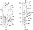
- the direction of movement of the first opening 3a relative to the fixed frame 4, during the first movement step is illustrated by the arrow F1 at Figures 5 to 7 .
- the first step of moving the first opening 3a relative to the fixed frame 4 is implemented by the electrical activation of the electromechanical actuator 6.
- the drive arm 18 When the first opening 3a is in the closed position relative to the fixed frame 4, the drive arm 18 is arranged inside a recess 37 of the first locking device 20, as illustrated in figure 5 .
- the recess 37 of the first locking device 20 is defined at a first end by the stop 31 of the movable arm 23 and at a second end by the assembly element 25 and, more particularly, by a stop 41 of the assembly element 25.
- the first end of the recess 37 is opposite the second end thereof.
- the shuttle 45 in particular the ramp 40 of the shuttle 45, is moved by means of the flexible element 9 and bears on the cam 32.
- the cam 32 is held in position by means of the aforementioned support stop, between the cam 32 and the movable arm 23.
- the cam 32 is stationary, around the axis of rotation Y2, during this movement of the first opening 3a relative to the fixed frame 4 from the closed position to the open position.
- the movable arm 23 is moved relative to the assembly element 25 and, more particularly, relative to the crosspiece 47 by a rotational movement R1 around the first axis of rotation Y1, as illustrated in figures 6 And 7 .
- the rotational movement R1 of the movable arm 23 relative to the assembly element 25 is implemented against the force of the first elastic return element arranged at the level of the first axis of rotation Y1.
- the method comprises a second step of moving the first opening leaf 3a relative to the fixed frame 4 from the open position to the locked half-open position of the first opening leaf 3a relative to the fixed frame 4.
- the locked half-open position of the first opening 3a relative to the fixed frame 4 corresponds to the position where the drive arm 18 is positioned inside the recess 37 of the first locking device 20.
- a so-called maximum locked half-open position of the first opening 3a relative to the fixed frame 4 corresponds to the drive arm 18 resting against the stop 31 of the movable arm 23, as illustrated in figure 10 .
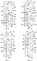
- the direction of movement of the first opening 3a relative to the fixed frame 4, during the second movement step is illustrated by the arrow F2 at figures 9 to 10 .
- the second step of moving the first opening 3a relative to the fixed frame 4 is implemented by the electrical activation of the electromechanical actuator 6.
- the support of the drive arm 18 against the stop 31 of the movable arm 23 makes it possible to prevent the movement of the first opening leaf 3a relative to the fixed frame 4 towards an open position of the first opening leaf 3a relative to the fixed frame 4.
- the movable arm 23, in particular the free end 23a of the movable arm 23, is moved relative to the assembly element 25 and, more particularly, relative to the crosspiece 47, in other words relative to a fixed part of the window 2, initially by a first rotational movement R1 about the first axis of rotation Y1, as illustrated in FIG. figure 9 , and, in a second step, by a second rotational movement R3 around the first axis of rotation Y1, as illustrated in figure 10 .
- the first rotational movement R1 around the first axis of rotation Y1 of the movable arm 23 is opposite to the second rotational movement R3 around the first axis of rotation Y1 of the movable arm 23.
- the first rotational movement R1 of the movable arm 23 relative to the assembly element 25 is implemented against the force of the first elastic return element arranged at the first axis of rotation Y1. Furthermore, the second rotational movement R3 about the first axis of rotation Y1 of the movable arm 23 relative to the assembly element 25 is implemented by the force exerted by the first elastic return element arranged at the first axis of rotation Y1.
- the movable arm 23 is moved into its rest position relative to the assembly element 25 and, more particularly, relative to the crosspiece 47 by the second rotational movement R3 around the first axis of rotation Y1, as illustrated in FIG. figure 10 .
- the cam 32 is moved relative to the movable arm 23 by a rotational movement R2 around the second axis of rotation Y2, as illustrated in figure 9 .
- the cam 32 is movable in rotation about the axis of rotation Y2 during this movement of the first opening leaf 3a relative to the fixed frame 4 from the open position to the locked half-open position of the first opening leaf 3a relative to the fixed frame 4.
- the second moving step may comprise a first sub-step of moving the first opening leaf 3a relative to the fixed frame 4 from the open position to a position where the drive arm 18 is located inside the recess 37 of the first locking device 20, then a second sub-step of moving the first opening leaf 3a relative to the fixed frame 4 from the position where the drive arm 18 is located inside the recess 37 of the first locking device 20 to the maximum locked half-open position of the first opening leaf 3a relative to the fixed frame 4.
- the direction of movement of the first opening leaf 3a relative to the fixed frame 4, during the first additional movement step corresponds to that of the arrow F2. Furthermore, the direction of movement of the first opening leaf 3a relative to the fixed frame 4, during the second additional movement step, corresponds to that of the arrow F1.
- the second movement step only comprises moving the first opening leaf 3a relative to the fixed frame 4 from the open position to the locked half-open position of the first opening leaf 3a relative to the fixed frame 4.
- the method comprises a step of stopping the first opening leaf 3a relative to the fixed frame 4 in the locked half-open position of the first opening leaf 3a relative to the fixed frame 4, as illustrated in figure 10 or to the figure 11 .
- step of stopping the first opening 3a relative to the fixed frame 4 is implemented by the electrical deactivation of the electromechanical actuator 6.
- the steps of the control method described above are implemented automatically by the motorized drive device 5 and, more particularly, by the electronic control unit 10, so as to reach the locked half-open position of the first opening 3a relative to the fixed frame 4.
- the method comprises a second control step, so as to deactivate the first locking device 20.
- the second control step is implemented by sending a control command to the electronic control unit 10 of the motorized drive device 5, in particular by means of one of the local 12 or central 13 control units or even a sensor.
- the second control step can thus be implemented manually, in particular by the user, or automatically.
- the method comprises a third step of moving the first opening 3a relative to the fixed frame 4 from the locked half-open position to the locked closed position.
- the direction of movement of the first opening 3a relative to the fixed frame 4, during the third movement step is illustrated by the arrow F2 at Figures 11 and 12 .
- the third step of moving the first opening 3a relative to the fixed frame 4 is implemented by the electrical activation of the electromechanical actuator 6.
- the deactivation of the first locking device 20 is implemented when the shuttle 45 is positioned inside the recess 37 of the first locking device 20 and, more particularly, when the cam 32 is moved to its rest position relative to the movable arm 23 by a rotational movement R4 around the second axis of rotation Y2, as illustrated in FIG. figure 5 .
- the deactivation of the first locking device 20 is put in operation only when the shuttle 45 is in the position corresponding to the locked closed position of the first opening 3a relative to the fixed frame 4.
- the movement of the cam 32 into its rest position relative to the movable arm 23 by the rotational movement R4 around the second axis of rotation Y2 is configured to be implemented only when the shuttle 45 is in the position corresponding to the locked closed position of the first opening 3a relative to the fixed frame 4.
- the first locking device 20 is configured to hold the first opening leaf 3a in a half-open position locked relative to the fixed frame 4, that is to say that the first locking device 20 is configured to prevent manual opening of the first opening leaf 3a relative to the fixed frame 4, in other words the drive arm 18 is retained inside the recess 37 of the first locking device 20 by the stop 31 of the movable arm 23.
- the control device 22 housed in the drive arm 18 activates the second locking device 21, in particular by tilting the drive element 30 inside the drive arm 18, so as to unlock the second locking device 21.
- the first opening 3a returns to its initial position relative to the fixed frame 4, as well as the movable arm 23 relative to the assembly element 25 and, more particularly, to the crosspiece 47, as well as the cam 32 relative to the movable arm 23, as prior to the first displacement step.
- the cam 32 when the first opening 3a is in the closed position locked relative to the sleeping frame 4, the cam 32 is in its rest position, in other words the cam 32 is no longer in contact with the shuttle 45, in particular the ramp 40 of the shuttle 45.
- the method comprises a step of monitoring the position of the first opening leaf 3a relative to the fixed frame 4.
- the monitoring step makes it possible to detect a movement of the first opening 3a relative to the fixed frame 4.
- the monitoring step is implemented by at least one position detection sensor of an output shaft of the electric motor 7 of the electromechanical actuator 6.
- the output shaft of the electric motor 7 of the electromechanical actuator 6 is driven in rotation through the motorized drive device 5.
- the movement of the first opening 3a relative to the fixed frame 4 is determined by the position detection sensor of the output shaft of the electric motor 7.
- the position detection sensor of the output shaft of the electric motor 7 is a Hall effect sensor.
- the monitoring step is implemented by at least one sensor for detecting the position of an output shaft of the electromechanical actuator 6.
- the monitoring step is implemented by at least one sensor for detecting the position of the first opening 3a relative to the fixed frame 4.
- position detection sensors are not limiting and may be different. They may include, in particular, one or more optical sensors.
- the monitoring step is implemented through the electronic control unit 10 of the motorized drive device 5.
- the method comprises a step of determining an attempted intrusion.
- the step of determining an intrusion attempt is inhibited.
- the movement of the first opening 3a relative to the fixed frame 4 detected during the monitoring step is considered to be a movement implemented voluntarily by a user.
- the monitoring step makes it possible to determine whether the movement of the first opening 3a relative to the fixed frame 4 is implemented manually.
- an attempted intrusion is determined in the case where the length of the movement of the first opening 3a relative to the fixed frame 4 is greater than a predetermined threshold value M during a predetermined period of time T.
- an attempted intrusion is determined in the case where the length of the displacement of the first opening 3a relative to the fixed frame 4 is greater than one centimeter over a period of time of one minute.
- the step of determining an attempted intrusion is implemented through the electronic control unit 10 of the motorized drive device 5.
- the method comprises a fourth step of moving the first opening 3a relative to the fixed frame 4 from the locked half-open position to the locked closed position.
- the direction of movement of the first opening 3a relative to the fixed frame 4, during the fourth movement step corresponds to that of the arrow F2.
- the fourth step of moving the first opening 3a relative to the fixed frame 4 is implemented by the electrical activation of the electromechanical actuator 6.
- This fourth movement step is implemented in a similar manner to the third movement step.
- the fourth step of the control method is implemented automatically by the motorized drive device 5 and, more particularly, by the electronic control unit 10, so as to place the first opening 3a relative to the fixed frame 4 in the closed position, itself locked by the second locking device 21.
- the window 2 and, more particularly, the building is protected against attempted intrusion by closing the first opening 3a relative to the fixed frame 4 by means of the motorized drive device 5.
- the method Prior to the fourth displacement step, the method comprises a step of waking up the electromechanical actuator 6 from a standby state.
- the method can also comprise a step of transmitting information to an alarm system, not shown.
- the alarm system can trigger a siren, so as to emit an audible signal, emit a notification to at least one mobile terminal, for example to a smartphone, so as to inform one or more users, and/or emit a notification to the central control unit, so as to command the closing of the screen of each concealment device, for example of each shutter.
- the first locking device makes it possible to lock the opening relative to the fixed frame in the locked half-open position by means of the motorized drive device.
- the first locking device makes it possible to ensure the ventilation of the building in a secure manner by a half-opening of the opening relative to the fixed frame, in particular by means of simple parts.
- the unlocking of the opening relative to the fixed frame in connection with the first locking device is implemented by means of the motorized drive device configured to generate a movement of the opening relative to the fixed frame passing through the closed and locked position of the opening relative to the fixed frame by means of the second locking device.
- the electronic control unit of the motorized drive device makes it possible to control the movement of the opening leaf relative to the fixed frame in order to lock the opening leaf relative to the fixed frame in the locked half-open position and to unlock the opening leaf relative to the fixed frame from the locked half-open position.
- the first locking device thus makes it possible to prohibit, or at least delay, an attempted intrusion by an individual.
- the motorized drive device 5 can be configured to slide several openings 3a, 3b by means of the flexible element 9, in the same direction of movement or in an opposite direction of movement.
- the electric motor 7 of the electromechanical actuator 6 may be of the asynchronous or direct current type.
Landscapes
- Power-Operated Mechanisms For Wings (AREA)
Claims (10)
- Steuerverfahren im Betrieb einer motorisierten Antriebsvorrichtung (5) eines Schiebefensters (2) für ein Gebäude,das Schiebefenster (2) umfassend:- einen Zargenrahmen (4),- mindestens einen Flügel (3a, 3b), und- eine erste Vorrichtung (20) zum Verriegeln des Flügels (3a) in Bezug auf den Zargenrahmen (4) in einer verriegelten Spaltstellung, wobei die verriegelte Spaltstellung zwischen einer offenen Stellung und einer geschlossenen Stellung des Flügels (3a) in Bezug auf den Zargenrahmen (4) angeordnet ist, die erste Verriegelungsvorrichtung (20) umfassend einen Arm (23), der um eine Drehachse (Y1) beweglich ist,dadurch gekennzeichnet, dass das Fenster (2) auch Folgendes umfasst:- eine motorisierte Antriebsvorrichtung (5), die konfiguriert ist, um den Flügel (3a) in Bezug auf die Einfassung (4) kippend zu bewegen, und- eine zweite Verriegelungsvorrichtung (21), die den Flügel (3a) in Bezug auf den Zargenrahmen (4) in der geschlossenen Stellung verriegelt und dadurch den Flügel (3a) in eine verriegelte geschlossene Stellung überführt,dadurch gekennzeichnet, dass die motorisierte Antriebsvorrichtung (5) Folgendes umfasst:- eine elektronische Steuereinheit (10),- einen elektromechanischen Stellantrieb (6), der elektromechanische Stellantrieb (6) umfassend mindestens einen Elektromotor (7),- ein flexibles Element (9), wobei das flexible Element (9) konfiguriert ist, um den Flügel (3a) in Bezug auf den Zargenrahmen (4) in Bewegung zu versetzen, wenn der elektromechanische Stellantrieb (6) elektrisch aktiviert wird, und- einen Antriebsarm (18), wobei der Antriebsarm (18) einerseits mit dem Flügel (3a) und andererseits mit dem flexiblen Element (9) verbunden ist,dass der Antriebsarm (18) mit dem beweglichen Arm (23) der ersten Verriegelungsvorrichtung (20) zusammenwirkt,dass der bewegliche Arm (23) den Antriebsarm (18) zwischen der verriegelten Spaltstellung und der geschlossenen Stellung des Flügels (3a) in Bezug auf den Zargenrahmen (4) hält, nach Überschreiten der verriegelten Spaltposition bei einer Bewegung des Flügels (3a) in Bezug auf die Einfassung (4) aus der verriegelten Spaltposition in die verriegelte Spaltposition. aus einer offenen Position in die geschlossene Position, implementiert durch die elektrische Aktivierung des elektromechanischen Stellantriebs (6), unddass die erste Verriegelungsvorrichtung (20) eine Freigabevorrichtung (29) des beweglichen Arms (23) in Bezug auf den Antriebsarm (18) umfasst, wobei die Freigabevorrichtung (29) nach Verriegeln des Flügels (3a) in Bezug auf den Zargenrahmen (4) in der geschlossenen Stellung mittels der zweiten Verriegelungsvorrichtung (21) aktiviert wird,und dass das Verfahren mindestens Folgendes umfasst:- einen Schritt eines Bewegens des Flügels (3a) in Bezug auf den Zargenrahmen (4) aus einer offenen Stellung in die verriegelte Spaltstellung des Flügels (3a) in Bezug auf den Zargenrahmen (4), implementiert durch die elektrische Aktivierung des elektromechanischen Aktuators (6),- nach Erreichen der verriegelten Spaltstellung des Flügels (3a) in Bezug auf den Zargenrahmen (4), einen Schritt eines Überwachens der Stellung des Flügels (3a) in Bezug auf den Zargenrahmen (4),- nach einer Erfassung einer Bewegung des Flügels (3a) in Bezug auf den Zargenrahmen (4) während des Überwachungsschritts, einen Schritt zur Bestimmung eines Einbruchsversuchs, und- in dem Fall, dass in dem Schritt zum Bestimmen eines Einbruchsversuchs ein Einbruchsversuch bestimmt wurde, einen weiteren Schritt eines Bewegens des Flügels (3a) in Bezug auf den Zargenrahmen (4) aus der verriegelten Spaltstellung in die verriegelte Schließstellung.
- Verfahren zur Steuerung im Betrieb einer motorisierten Antriebsvorrichtung (5) eines Schiebefensters (2) für ein Gebäude nach Anspruch 1, dadurch gekennzeichnet dass in dem Fall, dass ein Steuerbefehl von einer Steuereinheit (12, 13) oder einem Sensor ausgegeben wird, der Schritt des Bestimmens eines Einbruchsversuchs gesperrt wird.
- Verfahren zum Steuern im Betrieb einer motorisierten Antriebsvorrichtung (5) eines Schiebefensters (2) für ein Gebäude nach Anspruch 1 oder nach Anspruch 2, dadurch gekennzeichnet, dass ein Einbruchsversuch in dem Fall bestimmt wird, dass die Länge der Bewegung des Flügels (3a) in Bezug auf den Zargenrahmen (4) während einer vorbestimmten Zeitdauer (T) größer ist als ein vorbestimmter Schwellenwert (M).
- Verfahren zur Steuerung im Betrieb einer motorisierten Antriebsvorrichtung (5) eines Schiebefensters (2) für ein Gebäude nach einem der Ansprüche 1 bis 3, dadurch gekennzeichnet, dass der andere Bewegungsschritt automatisch durch die motorisierte Antriebsvorrichtung (5) durchgeführt wird, sodass der Flügel (3a) in Bezug auf den Zargenrahmen (4) in der geschlossenen Stellung angeordnet wird, die ihrerseits durch die zweite Verriegelungsvorrichtung (21) verriegelt wird.
- Verfahren zur Steuerung im Betrieb einer motorisierten Antriebsvorrichtung (5) eines Schiebefensters (2) für ein Gebäude nach einem der Ansprüche 1 bis 4, dadurch gekennzeichnet, dass in dem Fall, dass in dem Schritt eines Bestimmens eines Einbruchsversuchs ein Einbruchsversuch bestimmt wurde, das Verfahren einen Schritt eines Übermittelns einer Information an ein Alarmsystem umfasst.
- Steuerverfahren im Betrieb einer motorisierten Antriebsvorrichtung (5) eines Schiebefensters (2) für ein Gebäude nach Anspruch 5, dadurch gekennzeichnet, dass in dem Fall, dass in dem Schritt eines Bestimmens eines Einbruchsversuchs ein Einbruchsversuch bestimmt wurde, das Alarmsystem eine Sirene auslöst, um ein akustisches Signal auszugeben, eine Benachrichtigung an mindestens ein mobiles Endgerät sendet, um einen oder mehrere Benutzer zu informieren, und/oder eine Benachrichtigung an eine zentrale Steuereinheit sendet, um das Schließen eines Verdunkelungsvorrichtungsschirms zu befehlen.
- Verfahren zur Steuerung im Betrieb einer motorisierten Antriebsvorrichtung (5) eines Schiebefensters (2) für ein Gebäude nach einem der Ansprüche 1 bis 6, dadurch gekennzeichnet, dass das Verfahren vor dem anderen Schritt eines Bewegens einen Schritt eines Aufweckens des elektromechanischen Stellantriebs (6) aus einem Wachzustand umfasst.
- Schiebefenster (2) für ein Gebäude, das Schiebefenster (2) umfassend:- einen Zargenrahmen (4),- mindestens einen Flügel (3a, 3b), und- eine erste Vorrichtung (20) zum Verriegeln des Flügels (3a) in Bezug auf den Zargenrahmen (4) in einer verriegelten Spaltstellung, wobei die verriegelte Spaltstellung zwischen einer offenen Stellung und einer geschlossenen Stellung des Flügels (3a) in Bezug auf den Zargenrahmen (4) angeordnet ist, die erste Verriegelungsvorrichtung (20) umfassend einen Arm (23), der um eine Drehachse (Y1) beweglich ist,dadurch gekennzeichnet, dass das Fenster (2) auch Folgendes umfasst:- eine motorisierte Antriebsvorrichtung (5), die konfiguriert ist, um den Flügel (3a) in Bezug auf die Einfassung (4) kippend zu bewegen, und- eine zweite Vorrichtung (21) zum Verriegeln des Flügels (3a) in Bezug auf den Zargenrahmen (4) in der geschlossenen Stellung,dadurch gekennzeichnet, dass die motorisierte Antriebsvorrichtung (5) Folgendes umfasst:- eine elektronische Steuereinheit (10),- einen elektromechanischen Stellantrieb (6), der elektromechanische Stellantrieb (6) umfassend mindestens einen Elektromotor (7),- ein flexibles Element (9), wobei das flexible Element (9) konfiguriert ist, um den Flügel (3a) in Bezug auf den Zargenrahmen (4) in Bewegung zu versetzen, wenn der elektromechanische Stellantrieb (6) elektrisch aktiviert wird, und- einen Antriebsarm (18), wobei der Antriebsarm (18) einerseits mit dem Flügel (3a) und andererseits mit dem flexiblen Element (9) verbunden ist,dass der Antriebsarm (18) mit dem beweglichen Arm (23) der ersten Verriegelungsvorrichtung (20) zusammenwirkt,dass der bewegliche Arm (23) den Antriebsarm (18) zwischen der verriegelten Spaltstellung und der geschlossenen Stellung des Flügels (3a) in Bezug auf den Zargenrahmen (4) hält, nach Überschreiten der verriegelten Spaltposition bei einer Bewegung des Flügels (3a) in Bezug auf die Einfassung (4) aus der verriegelten Spaltposition in die verriegelte Spaltposition. aus einer offenen Position in die geschlossene Position, implementiert durch die elektrische Aktivierung des elektromechanischen Stellantriebs (6), unddass die erste Verriegelungsvorrichtung (20) eine Freigabevorrichtung (29) des beweglichen Arms (23) in Bezug auf den Antriebsarm (18) umfasst, wobei die Freigabevorrichtung (29) nach Verriegeln des Flügels (3a) in Bezug auf den Zargenrahmen (4) in der geschlossenen Stellung mittels der zweiten Verriegelungsvorrichtung (21) aktiviert wird,und dass die elektronische Steuereinheit (10) konfiguriert ist, um die Schritte des Verfahrens gemäß einem der Ansprüche 1 bis 7 durchzuführen.
- Schiebefenster (2) für ein Gebäude nach Anspruch 8, dadurch gekennzeichnet, dass der elektromechanische Stellantrieb (6) vom reversiblen Typ ist.
- Hausautomationsanlage, dadurch gekennzeichnet, dass die Anlage ein Schiebefenster (2) nach Anspruch 8 oder Anspruch 9 umfasst.
Applications Claiming Priority (3)
| Application Number | Priority Date | Filing Date | Title |
|---|---|---|---|
| FR1756731A FR3069007B1 (fr) | 2017-07-17 | 2017-07-17 | Fenetre coulissante pour un batiment et installation domotique comprenant une telle fenetre, ainsi que procede de commande associe |
| PCT/EP2018/069285 WO2019016147A1 (fr) | 2017-07-17 | 2018-07-16 | Fenêtre coulissante pour un bâtiment et installation domotique comprenant une telle fenêtre coulissante, ainsi que procédé de commande associé |
| EP18737936.7A EP3655606B1 (de) | 2017-07-17 | 2018-07-16 | Schiebefenster für eine gebäude- und heimautomatisierungsanlage mit einem solchen schiebefenster und zugehöriges steuerungsverfahren |
Related Parent Applications (2)
| Application Number | Title | Priority Date | Filing Date |
|---|---|---|---|
| EP18737936.7A Division EP3655606B1 (de) | 2017-07-17 | 2018-07-16 | Schiebefenster für eine gebäude- und heimautomatisierungsanlage mit einem solchen schiebefenster und zugehöriges steuerungsverfahren |
| EP18737936.7A Division-Into EP3655606B1 (de) | 2017-07-17 | 2018-07-16 | Schiebefenster für eine gebäude- und heimautomatisierungsanlage mit einem solchen schiebefenster und zugehöriges steuerungsverfahren |
Publications (2)
| Publication Number | Publication Date |
|---|---|
| EP4008866A1 EP4008866A1 (de) | 2022-06-08 |
| EP4008866B1 true EP4008866B1 (de) | 2024-08-14 |
Family
ID=60080975
Family Applications (2)
| Application Number | Title | Priority Date | Filing Date |
|---|---|---|---|
| EP18737936.7A Active EP3655606B1 (de) | 2017-07-17 | 2018-07-16 | Schiebefenster für eine gebäude- und heimautomatisierungsanlage mit einem solchen schiebefenster und zugehöriges steuerungsverfahren |
| EP22152194.1A Active EP4008866B1 (de) | 2017-07-17 | 2018-07-16 | Verfahren zur betriebssteuerung einer motorisierten antriebsvorrichtung eines schiebefensters für ein gebäude, entsprechendes fenster und entsprechende haustechnikanlage |
Family Applications Before (1)
| Application Number | Title | Priority Date | Filing Date |
|---|---|---|---|
| EP18737936.7A Active EP3655606B1 (de) | 2017-07-17 | 2018-07-16 | Schiebefenster für eine gebäude- und heimautomatisierungsanlage mit einem solchen schiebefenster und zugehöriges steuerungsverfahren |
Country Status (3)
| Country | Link |
|---|---|
| EP (2) | EP3655606B1 (de) |
| FR (1) | FR3069007B1 (de) |
| WO (1) | WO2019016147A1 (de) |
Families Citing this family (1)
| Publication number | Priority date | Publication date | Assignee | Title |
|---|---|---|---|---|
| FR3101904B1 (fr) | 2019-10-09 | 2021-10-29 | Somfy Activites Sa | Procédé de commande en fonctionnement d’un dispositif d’entraînement motorisé d’une fenêtre coulissante pour un bâtiment, fenêtre et installation domotique associées |
Family Cites Families (3)
| Publication number | Priority date | Publication date | Assignee | Title |
|---|---|---|---|---|
| US3352586A (en) * | 1965-09-20 | 1967-11-14 | Paulyne Hakanson M | Locking device for sliding windows and doors |
| JP2006194065A (ja) * | 2004-12-17 | 2006-07-27 | Hamada Kousyou Co Ltd | 窓(扉、戸等の開閉手段を含む)のロック及び/又は開閉を自動制御する窓の自動開閉システム |
| KR20090098240A (ko) * | 2008-03-13 | 2009-09-17 | (주) 중앙디자인 | 창문 개폐장치 |
-
2017
- 2017-07-17 FR FR1756731A patent/FR3069007B1/fr active Active
-
2018
- 2018-07-16 EP EP18737936.7A patent/EP3655606B1/de active Active
- 2018-07-16 EP EP22152194.1A patent/EP4008866B1/de active Active
- 2018-07-16 WO PCT/EP2018/069285 patent/WO2019016147A1/fr not_active Ceased
Also Published As
| Publication number | Publication date |
|---|---|
| EP3655606A1 (de) | 2020-05-27 |
| FR3069007B1 (fr) | 2019-08-23 |
| FR3069007A1 (fr) | 2019-01-18 |
| EP4008866A1 (de) | 2022-06-08 |
| EP3655606B1 (de) | 2026-04-29 |
| WO2019016147A1 (fr) | 2019-01-24 |
Similar Documents
| Publication | Publication Date | Title |
|---|---|---|
| EP3722547B1 (de) | Motorisierte antriebsvorrichtung, entsprechendes schiebefenster für ein gebäude und entsprechende haustechnikanlage | |
| EP3571368B1 (de) | Schiebefenster für ein gebäude, heimautomatisierungsanlage mit solch einem schiebefenster und verfahren zur steuerung des betriebs einer motorisierten antriebsvorrichtung für solch ein fenster | |
| EP3510227B1 (de) | Schiebefenster für ein gebäude- und heimautomationssystem mit solch einem schiebefenster | |
| EP3530857B1 (de) | Betriebssteuerungsverfahren einer motorisierten antriebsvorrichtung eines fensters für ein gebäude, entsprechendes fenster und entsprechende haustechnikanlage | |
| FR3069008A1 (fr) | Fenetre coulissante pour un batiment et installation domotique comprenant une telle fenetre coulissante, ainsi que procede de commande associe | |
| EP3216963B1 (de) | Dreh-kippfenster für ein gebäude, und hausanlage, die ein solches dreh-kippfenster umfasst | |
| EP3655606B1 (de) | Schiebefenster für eine gebäude- und heimautomatisierungsanlage mit einem solchen schiebefenster und zugehöriges steuerungsverfahren | |
| EP3529439B1 (de) | Verfahren zur steuerung des betriebs einer motorisierten antriebsvorrichtung eines schiebefensters für ein gebäude | |
| EP3333349B1 (de) | Dreh-kippfenster für ein gebäude, hausanlage, die ein solches dreh-kippfenster umfasst, und betriebssteuerungsverfahren einer motorisierten antriebsvorrichtung für ein solches fenster | |
| EP3190253B1 (de) | Dreh-kippfenster für ein gebäude, und hausanlage, die ein solches dreh-kippfenster umfasst | |
| EP3805503B1 (de) | Verfahren zur steuerung der funktion eines motorischen antriebs eines gebäudeschiebefensteres, in verbindung mit einem fenster und einem hausautomationssystem | |
| EP3517721B1 (de) | Schiebefenster für ein gebäude, und heimtechnikanlage, die ein solches schiebefenster umfasst | |
| EP3805492B1 (de) | Verfahren zur steuerung der funktion eines motorischen antriebs eines gebäudeschiebefensteres, in verbindung mit einem fenster und einem hausautomationssystem | |
| EP4116535B1 (de) | Verfahren zur betriebssteuerung einer motorisierten antriebsvorrichtung eines schiebefensters für ein gebäude, entsprechendes fenster und entsprechende haustechnikanlage | |
| EP3805505A1 (de) | Verfahren zur steuerung der funktion eines motorischen antriebs eines gebäudeschiebefensteres, in verbindung mit einem fenster und einem hausautomationssystem | |
| FR3079259A1 (fr) | Fenetre coulissante pour un batiment et installation domotique comprenant une telle fenetre coulissante | |
| FR3095000A1 (fr) | Dispositif d’entraînement motorisé, fenêtre coulissante pour un bâtiment et installation domotique associées | |
| FR3139592A1 (fr) | Dispositif d’entraînement motorisé d’un dispositif d’occultation et dispositif d’occultation associé |
Legal Events
| Date | Code | Title | Description |
|---|---|---|---|
| PUAI | Public reference made under article 153(3) epc to a published international application that has entered the european phase |
Free format text: ORIGINAL CODE: 0009012 |
|
| STAA | Information on the status of an ep patent application or granted ep patent |
Free format text: STATUS: THE APPLICATION HAS BEEN PUBLISHED |
|
| AC | Divisional application: reference to earlier application |
Ref document number: 3655606 Country of ref document: EP Kind code of ref document: P |
|
| AK | Designated contracting states |
Kind code of ref document: A1 Designated state(s): AL AT BE BG CH CY CZ DE DK EE ES FI FR GB GR HR HU IE IS IT LI LT LU LV MC MK MT NL NO PL PT RO RS SE SI SK SM TR |
|
| STAA | Information on the status of an ep patent application or granted ep patent |
Free format text: STATUS: REQUEST FOR EXAMINATION WAS MADE |
|
| 17P | Request for examination filed |
Effective date: 20221124 |
|
| RBV | Designated contracting states (corrected) |
Designated state(s): AL AT BE BG CH CY CZ DE DK EE ES FI FR GB GR HR HU IE IS IT LI LT LU LV MC MK MT NL NO PL PT RO RS SE SI SK SM TR |
|
| GRAP | Despatch of communication of intention to grant a patent |
Free format text: ORIGINAL CODE: EPIDOSNIGR1 |
|
| STAA | Information on the status of an ep patent application or granted ep patent |
Free format text: STATUS: GRANT OF PATENT IS INTENDED |
|
| INTG | Intention to grant announced |
Effective date: 20240402 |
|
| GRAS | Grant fee paid |
Free format text: ORIGINAL CODE: EPIDOSNIGR3 |
|
| GRAA | (expected) grant |
Free format text: ORIGINAL CODE: 0009210 |
|
| STAA | Information on the status of an ep patent application or granted ep patent |
Free format text: STATUS: THE PATENT HAS BEEN GRANTED |
|
| AC | Divisional application: reference to earlier application |
Ref document number: 3655606 Country of ref document: EP Kind code of ref document: P |
|
| AK | Designated contracting states |
Kind code of ref document: B1 Designated state(s): AL AT BE BG CH CY CZ DE DK EE ES FI FR GB GR HR HU IE IS IT LI LT LU LV MC MK MT NL NO PL PT RO RS SE SI SK SM TR |
|
| REG | Reference to a national code |
Ref country code: GB Ref legal event code: FG4D Free format text: NOT ENGLISH |
|
| RIN1 | Information on inventor provided before grant (corrected) |
Inventor name: BUFFLIER, NADEGE Inventor name: HOFF, LAURENT Inventor name: EICHLER, MICKAEL Inventor name: CRON, JULIEN Inventor name: BEAU, STEPHANE Inventor name: CAVAREC, PIERRE-EMMANUEL |
|
| REG | Reference to a national code |
Ref country code: CH Ref legal event code: EP |
|
| REG | Reference to a national code |
Ref country code: DE Ref legal event code: R096 Ref document number: 602018073269 Country of ref document: DE |
|
| REG | Reference to a national code |
Ref country code: IE Ref legal event code: FG4D Free format text: LANGUAGE OF EP DOCUMENT: FRENCH |
|
| REG | Reference to a national code |
Ref country code: LT Ref legal event code: MG9D |
|
| REG | Reference to a national code |
Ref country code: NL Ref legal event code: MP Effective date: 20240814 |
|
| PG25 | Lapsed in a contracting state [announced via postgrant information from national office to epo] |
Ref country code: NO Free format text: LAPSE BECAUSE OF FAILURE TO SUBMIT A TRANSLATION OF THE DESCRIPTION OR TO PAY THE FEE WITHIN THE PRESCRIBED TIME-LIMIT Effective date: 20241114 |
|
| REG | Reference to a national code |
Ref country code: AT Ref legal event code: MK05 Ref document number: 1713446 Country of ref document: AT Kind code of ref document: T Effective date: 20240814 |
|
| PG25 | Lapsed in a contracting state [announced via postgrant information from national office to epo] |
Ref country code: FI Free format text: LAPSE BECAUSE OF FAILURE TO SUBMIT A TRANSLATION OF THE DESCRIPTION OR TO PAY THE FEE WITHIN THE PRESCRIBED TIME-LIMIT Effective date: 20240814 Ref country code: GR Free format text: LAPSE BECAUSE OF FAILURE TO SUBMIT A TRANSLATION OF THE DESCRIPTION OR TO PAY THE FEE WITHIN THE PRESCRIBED TIME-LIMIT Effective date: 20241115 Ref country code: NL Free format text: LAPSE BECAUSE OF FAILURE TO SUBMIT A TRANSLATION OF THE DESCRIPTION OR TO PAY THE FEE WITHIN THE PRESCRIBED TIME-LIMIT Effective date: 20240814 Ref country code: PT Free format text: LAPSE BECAUSE OF FAILURE TO SUBMIT A TRANSLATION OF THE DESCRIPTION OR TO PAY THE FEE WITHIN THE PRESCRIBED TIME-LIMIT Effective date: 20241216 Ref country code: PL Free format text: LAPSE BECAUSE OF FAILURE TO SUBMIT A TRANSLATION OF THE DESCRIPTION OR TO PAY THE FEE WITHIN THE PRESCRIBED TIME-LIMIT Effective date: 20240814 |
|
| PG25 | Lapsed in a contracting state [announced via postgrant information from national office to epo] |
Ref country code: BG Free format text: LAPSE BECAUSE OF FAILURE TO SUBMIT A TRANSLATION OF THE DESCRIPTION OR TO PAY THE FEE WITHIN THE PRESCRIBED TIME-LIMIT Effective date: 20240814 |
|
| PG25 | Lapsed in a contracting state [announced via postgrant information from national office to epo] |
Ref country code: LV Free format text: LAPSE BECAUSE OF FAILURE TO SUBMIT A TRANSLATION OF THE DESCRIPTION OR TO PAY THE FEE WITHIN THE PRESCRIBED TIME-LIMIT Effective date: 20240814 |
|
| PG25 | Lapsed in a contracting state [announced via postgrant information from national office to epo] |
Ref country code: IS Free format text: LAPSE BECAUSE OF FAILURE TO SUBMIT A TRANSLATION OF THE DESCRIPTION OR TO PAY THE FEE WITHIN THE PRESCRIBED TIME-LIMIT Effective date: 20241214 Ref country code: AT Free format text: LAPSE BECAUSE OF FAILURE TO SUBMIT A TRANSLATION OF THE DESCRIPTION OR TO PAY THE FEE WITHIN THE PRESCRIBED TIME-LIMIT Effective date: 20240814 |
|
| PG25 | Lapsed in a contracting state [announced via postgrant information from national office to epo] |
Ref country code: HR Free format text: LAPSE BECAUSE OF FAILURE TO SUBMIT A TRANSLATION OF THE DESCRIPTION OR TO PAY THE FEE WITHIN THE PRESCRIBED TIME-LIMIT Effective date: 20240814 |
|
| PG25 | Lapsed in a contracting state [announced via postgrant information from national office to epo] |
Ref country code: RS Free format text: LAPSE BECAUSE OF FAILURE TO SUBMIT A TRANSLATION OF THE DESCRIPTION OR TO PAY THE FEE WITHIN THE PRESCRIBED TIME-LIMIT Effective date: 20241114 Ref country code: ES Free format text: LAPSE BECAUSE OF FAILURE TO SUBMIT A TRANSLATION OF THE DESCRIPTION OR TO PAY THE FEE WITHIN THE PRESCRIBED TIME-LIMIT Effective date: 20240814 |
|
| PG25 | Lapsed in a contracting state [announced via postgrant information from national office to epo] |
Ref country code: RS Free format text: LAPSE BECAUSE OF FAILURE TO SUBMIT A TRANSLATION OF THE DESCRIPTION OR TO PAY THE FEE WITHIN THE PRESCRIBED TIME-LIMIT Effective date: 20241114 Ref country code: PT Free format text: LAPSE BECAUSE OF FAILURE TO SUBMIT A TRANSLATION OF THE DESCRIPTION OR TO PAY THE FEE WITHIN THE PRESCRIBED TIME-LIMIT Effective date: 20241216 Ref country code: PL Free format text: LAPSE BECAUSE OF FAILURE TO SUBMIT A TRANSLATION OF THE DESCRIPTION OR TO PAY THE FEE WITHIN THE PRESCRIBED TIME-LIMIT Effective date: 20240814 Ref country code: NO Free format text: LAPSE BECAUSE OF FAILURE TO SUBMIT A TRANSLATION OF THE DESCRIPTION OR TO PAY THE FEE WITHIN THE PRESCRIBED TIME-LIMIT Effective date: 20241114 Ref country code: NL Free format text: LAPSE BECAUSE OF FAILURE TO SUBMIT A TRANSLATION OF THE DESCRIPTION OR TO PAY THE FEE WITHIN THE PRESCRIBED TIME-LIMIT Effective date: 20240814 Ref country code: LV Free format text: LAPSE BECAUSE OF FAILURE TO SUBMIT A TRANSLATION OF THE DESCRIPTION OR TO PAY THE FEE WITHIN THE PRESCRIBED TIME-LIMIT Effective date: 20240814 Ref country code: IS Free format text: LAPSE BECAUSE OF FAILURE TO SUBMIT A TRANSLATION OF THE DESCRIPTION OR TO PAY THE FEE WITHIN THE PRESCRIBED TIME-LIMIT Effective date: 20241214 Ref country code: HR Free format text: LAPSE BECAUSE OF FAILURE TO SUBMIT A TRANSLATION OF THE DESCRIPTION OR TO PAY THE FEE WITHIN THE PRESCRIBED TIME-LIMIT Effective date: 20240814 Ref country code: GR Free format text: LAPSE BECAUSE OF FAILURE TO SUBMIT A TRANSLATION OF THE DESCRIPTION OR TO PAY THE FEE WITHIN THE PRESCRIBED TIME-LIMIT Effective date: 20241115 Ref country code: FI Free format text: LAPSE BECAUSE OF FAILURE TO SUBMIT A TRANSLATION OF THE DESCRIPTION OR TO PAY THE FEE WITHIN THE PRESCRIBED TIME-LIMIT Effective date: 20240814 Ref country code: ES Free format text: LAPSE BECAUSE OF FAILURE TO SUBMIT A TRANSLATION OF THE DESCRIPTION OR TO PAY THE FEE WITHIN THE PRESCRIBED TIME-LIMIT Effective date: 20240814 Ref country code: BG Free format text: LAPSE BECAUSE OF FAILURE TO SUBMIT A TRANSLATION OF THE DESCRIPTION OR TO PAY THE FEE WITHIN THE PRESCRIBED TIME-LIMIT Effective date: 20240814 Ref country code: AT Free format text: LAPSE BECAUSE OF FAILURE TO SUBMIT A TRANSLATION OF THE DESCRIPTION OR TO PAY THE FEE WITHIN THE PRESCRIBED TIME-LIMIT Effective date: 20240814 |
|
| PG25 | Lapsed in a contracting state [announced via postgrant information from national office to epo] |
Ref country code: RO Free format text: LAPSE BECAUSE OF FAILURE TO SUBMIT A TRANSLATION OF THE DESCRIPTION OR TO PAY THE FEE WITHIN THE PRESCRIBED TIME-LIMIT Effective date: 20240814 Ref country code: SM Free format text: LAPSE BECAUSE OF FAILURE TO SUBMIT A TRANSLATION OF THE DESCRIPTION OR TO PAY THE FEE WITHIN THE PRESCRIBED TIME-LIMIT Effective date: 20240814 Ref country code: DK Free format text: LAPSE BECAUSE OF FAILURE TO SUBMIT A TRANSLATION OF THE DESCRIPTION OR TO PAY THE FEE WITHIN THE PRESCRIBED TIME-LIMIT Effective date: 20240814 |
|
| PG25 | Lapsed in a contracting state [announced via postgrant information from national office to epo] |
Ref country code: EE Free format text: LAPSE BECAUSE OF FAILURE TO SUBMIT A TRANSLATION OF THE DESCRIPTION OR TO PAY THE FEE WITHIN THE PRESCRIBED TIME-LIMIT Effective date: 20240814 |
|
| PG25 | Lapsed in a contracting state [announced via postgrant information from national office to epo] |
Ref country code: CZ Free format text: LAPSE BECAUSE OF FAILURE TO SUBMIT A TRANSLATION OF THE DESCRIPTION OR TO PAY THE FEE WITHIN THE PRESCRIBED TIME-LIMIT Effective date: 20240814 |
|
| PG25 | Lapsed in a contracting state [announced via postgrant information from national office to epo] |
Ref country code: SK Free format text: LAPSE BECAUSE OF FAILURE TO SUBMIT A TRANSLATION OF THE DESCRIPTION OR TO PAY THE FEE WITHIN THE PRESCRIBED TIME-LIMIT Effective date: 20240814 Ref country code: IT Free format text: LAPSE BECAUSE OF FAILURE TO SUBMIT A TRANSLATION OF THE DESCRIPTION OR TO PAY THE FEE WITHIN THE PRESCRIBED TIME-LIMIT Effective date: 20240814 |
|
| REG | Reference to a national code |
Ref country code: DE Ref legal event code: R097 Ref document number: 602018073269 Country of ref document: DE |
|
| PLBE | No opposition filed within time limit |
Free format text: ORIGINAL CODE: 0009261 |
|
| STAA | Information on the status of an ep patent application or granted ep patent |
Free format text: STATUS: NO OPPOSITION FILED WITHIN TIME LIMIT |
|
| PGFP | Annual fee paid to national office [announced via postgrant information from national office to epo] |
Ref country code: FR Payment date: 20250616 Year of fee payment: 8 |
|
| 26N | No opposition filed |
Effective date: 20250515 |
|
| PG25 | Lapsed in a contracting state [announced via postgrant information from national office to epo] |
Ref country code: SE Free format text: LAPSE BECAUSE OF FAILURE TO SUBMIT A TRANSLATION OF THE DESCRIPTION OR TO PAY THE FEE WITHIN THE PRESCRIBED TIME-LIMIT Effective date: 20240814 |
|
| PGFP | Annual fee paid to national office [announced via postgrant information from national office to epo] |
Ref country code: DE Payment date: 20250711 Year of fee payment: 8 |
|
| REG | Reference to a national code |
Ref country code: CH Ref legal event code: H13 Free format text: ST27 STATUS EVENT CODE: U-0-0-H10-H13 (AS PROVIDED BY THE NATIONAL OFFICE) Effective date: 20260224 |
|
| PG25 | Lapsed in a contracting state [announced via postgrant information from national office to epo] |
Ref country code: LU Free format text: LAPSE BECAUSE OF NON-PAYMENT OF DUE FEES Effective date: 20250716 |
|
| GBPC | Gb: european patent ceased through non-payment of renewal fee |
Effective date: 20250716 |
|
| REG | Reference to a national code |
Ref country code: BE Ref legal event code: MM Effective date: 20250731 |
|
| PG25 | Lapsed in a contracting state [announced via postgrant information from national office to epo] |
Ref country code: GB Free format text: LAPSE BECAUSE OF NON-PAYMENT OF DUE FEES Effective date: 20250716 |
|
| PG25 | Lapsed in a contracting state [announced via postgrant information from national office to epo] |
Ref country code: BE Free format text: LAPSE BECAUSE OF NON-PAYMENT OF DUE FEES Effective date: 20250731 |
|
| PG25 | Lapsed in a contracting state [announced via postgrant information from national office to epo] |
Ref country code: CH Free format text: LAPSE BECAUSE OF NON-PAYMENT OF DUE FEES Effective date: 20250731 |