EP4008868B1 - Loquet magnétique pour fixer un élément de fermeture à charnière à un support - Google Patents
Loquet magnétique pour fixer un élément de fermeture à charnière à un support Download PDFInfo
- Publication number
- EP4008868B1 EP4008868B1 EP21212386.3A EP21212386A EP4008868B1 EP 4008868 B1 EP4008868 B1 EP 4008868B1 EP 21212386 A EP21212386 A EP 21212386A EP 4008868 B1 EP4008868 B1 EP 4008868B1
- Authority
- EP
- European Patent Office
- Prior art keywords
- housing
- latch bolt
- latch
- magnetic
- assembly
- Prior art date
- Legal status (The legal status is an assumption and is not a legal conclusion. Google has not performed a legal analysis and makes no representation as to the accuracy of the status listed.)
- Active
Links
Images











Classifications
-
- E—FIXED CONSTRUCTIONS
- E05—LOCKS; KEYS; WINDOW OR DOOR FITTINGS; SAFES
- E05C—BOLTS OR FASTENING DEVICES FOR WINGS, SPECIALLY FOR DOORS OR WINDOWS
- E05C19/00—Other devices specially designed for securing wings, e.g. with suction cups
- E05C19/16—Devices holding the wing by magnetic or electromagnetic attraction
- E05C19/163—Devices holding the wing by magnetic or electromagnetic attraction a movable bolt being held in the striker by a permanent magnet
-
- E—FIXED CONSTRUCTIONS
- E05—LOCKS; KEYS; WINDOW OR DOOR FITTINGS; SAFES
- E05B—LOCKS; ACCESSORIES THEREFOR; HANDCUFFS
- E05B63/00—Locks or fastenings with special structural characteristics
- E05B63/04—Locks or fastenings with special structural characteristics for alternative use on the right-hand or left-hand side of wings
-
- E—FIXED CONSTRUCTIONS
- E05—LOCKS; KEYS; WINDOW OR DOOR FITTINGS; SAFES
- E05B—LOCKS; ACCESSORIES THEREFOR; HANDCUFFS
- E05B65/00—Locks or fastenings for special use
- E05B65/0007—Locks or fastenings for special use for gates
-
- E—FIXED CONSTRUCTIONS
- E05—LOCKS; KEYS; WINDOW OR DOOR FITTINGS; SAFES
- E05C—BOLTS OR FASTENING DEVICES FOR WINGS, SPECIALLY FOR DOORS OR WINDOWS
- E05C1/00—Fastening devices with bolts moving rectilinearly
- E05C1/004—Fastening devices with bolts moving rectilinearly parallel to the surface on which the fastener is mounted
- E05C1/006—Fastening devices with bolts moving rectilinearly parallel to the surface on which the fastener is mounted parallel to the wing edge
-
- E—FIXED CONSTRUCTIONS
- E05—LOCKS; KEYS; WINDOW OR DOOR FITTINGS; SAFES
- E05C—BOLTS OR FASTENING DEVICES FOR WINGS, SPECIALLY FOR DOORS OR WINDOWS
- E05C1/00—Fastening devices with bolts moving rectilinearly
- E05C1/08—Fastening devices with bolts moving rectilinearly with latching action
- E05C1/12—Fastening devices with bolts moving rectilinearly with latching action with operating handle or equivalent member moving otherwise than rigidly with the latch
- E05C1/16—Fastening devices with bolts moving rectilinearly with latching action with operating handle or equivalent member moving otherwise than rigidly with the latch the handle or member moving essentially in a plane substantially parallel to the wing or frame
- E05C1/166—Fastening devices with bolts moving rectilinearly with latching action with operating handle or equivalent member moving otherwise than rigidly with the latch the handle or member moving essentially in a plane substantially parallel to the wing or frame with sliding handle
-
- E—FIXED CONSTRUCTIONS
- E05—LOCKS; KEYS; WINDOW OR DOOR FITTINGS; SAFES
- E05C—BOLTS OR FASTENING DEVICES FOR WINGS, SPECIALLY FOR DOORS OR WINDOWS
- E05C19/00—Other devices specially designed for securing wings, e.g. with suction cups
- E05C19/16—Devices holding the wing by magnetic or electromagnetic attraction
- E05C19/166—Devices holding the wing by magnetic or electromagnetic attraction electromagnetic
- E05C19/168—Devices holding the wing by magnetic or electromagnetic attraction electromagnetic a movable bolt being electromagnetically held in the striker by electromagnetic attraction
Definitions
- the present invention relates to a magnetic latch for fastening a hinged closure member to a support.
- a magnetic latch assembly comprises a latch bolt assembly configured to be mounted to one of the hinged closure member and the support and a magnet keeper assembly configured to be mounted to the other one of the hinged closure member and the support.
- the magnetic latch assembly can be mounted on various types of closure members, in particular a door or a gate.
- closure members in particular a door or a gate.
- Most of these regulations specify a minimum height for the safety gates, a minimum height at which the actuator for opening the closure member are to be located, and/or required minimal and/or maximal force required to actuate the actuator.
- a common way to meet these requirements is by mounting the latch bolt assembly in an upright position on top of the gate with the actuator on the upper side of the latch bolt assembly.
- the actuator is typically a knob that has to be pulled upwards in order to open the closure member.
- a first kind of known magnetic latch assembly for a hinged closure system comprises a latch bolt assembly and a magnet assembly.
- the magnet assembly is mounted on the fixed support of the closure system and the latch bolt assembly is mounted on the moveable closure member of the closure system.
- the latch bolt assembly comprises a horizontal latch bolt that is moveable between an latching position where it may engage the magnet assembly to fasten the closure member and a retracted position where it is retracted within the latch bolt assembly so that the closure member may be opened.
- a compression spring is disposed around the latch bolt in order to bias the latch bolt to the retracted position.
- the magnet assembly has a vertical housing with an actuation handle provided on top of the housing and a magnet being positioned near the bottom of the housing.
- the magnet is coupled to the actuation handle by an elongate bar.
- the magnet is moveable between an upper position where the magnet cannot sufficiently attract the latch bolt to pull its towards its latching position and a lower position where the magnet can engage the latch bolt to pull its towards its latching position.
- a compression spring is provided to urge the magnet towards its lower position. Pulling the actuation handle upwards in turn pulls the magnet towards its upper position against the force of the compression spring.
- the latch bolt is attracted by the magnet within the magnet assembly, which magnet is in its lower position, and is displaced to its latching position against the force of the compression spring thus engaging the magnet assembly and fastening the closure member.
- the magnet When actuating the handle, the magnet is moved to its upper position thus increasing the distance between the magnet and the latch bolt and decreasing the magnetic attraction so that the compression spring pulls the latch bolt to its retracted position to open the closure member.
- Such assemblies are disclosed in AU 2009/251007 A1 , AU 2013/206766 A1 , 2014/203446 A1 , AU 2016/201778 A1 , and AU 2018/256525 A1 .
- AU 2013/206766 A1 further discloses that safety may be improved by having an actuation handle that may only be pulled upwards after a central area within the handle has been depressed. More specifically, depressing the central handle area causes a pawl to be horizontally displaced thereby allowing an upwards movement of the elongate bar. Additional safety measures are also disclosed in AU 2014/203446 A1 where the actuation handle requires a rotational motion followed by an upwards pulling motion in order to move the magnet towards its upper, i.e. disengaged, position.
- a downside of such improved safety measures is that the opening requires a series of complicated motions which may be difficult for a user to execute.
- AU 2016/201778 A1 and AU 2018/256525 A1 further disclose that the latch bolt assembly is provided with a key cylinder that may be used to lock the latch bolt.
- the main purpose of the key cylinder is to lock the latch bar in its latching position such that the closure member cannot be opened by the magnet assembly.
- a downside of these locking mechanism is that the latch bolt mechanism is positioned quite low and may be in reach of children. Moreover, the locking mechanism is used to lock the latch bar in its latching position. This may pose a danger in case a user locks the locking mechanism while the gate is opened as this may prevent the latch bolt from entering the keeper and thus leave the gate unfastened.
- knob may be difficult to lift. More specifically, the force required to lift the knob in combination with the height at which the knob is positioned may make it difficult for a user (in particular a user of low height) to unfasten the closure member.
- the magnet and the latch bolt are unlocked in a sideways fashion. More specifically, the magnet is pulled sideways with respect to the direction in which the latch bolt is attracted thereto. Such sideways motion typically requires a smaller force when compared to moving the latch bolt in the opposite direction of the magnetic attraction. This small force also means that the knob may be more easily lifted which may be a safety concern as children may be able to lift the knob.
- a second kind of magnetic latch assembly for a hinged closure system comprises a magnet assembly mounted on the closure member and a latch bolt assembly mounted on the fixed post.
- the magnet assembly includes a striker that is fixed to the closure member and has a free end which partially extends beyond the closure member towards the support.
- the striker acts as a stop against the fixed post with a magnet being provided in the free end thereof.
- the latch bolt assembly includes a vertically oriented latch bolt moveable between an latching position and a retracted position with a compression spring urging the latch bolt to its retracted position and with the magnet pulling the latch bolt to its latching position to fasten the closure member.
- a pull knob is provided on the latch bolt assembly and is connected to the latch bolt via a link bar to allow the latch bolt to be pulled into its retracted position against the force of the magnet to open the closure member.
- a key cylinder is provided on the latch bolt assembly to allow to lock the latch bolt in its latching position. More specifically, the key cylinder is positioned besides the link bar and rotation of the cylinder causes the cylinder to interlock with a groove provided in the link bar.
- Such assemblies are disclosed in WO 92/03631 A1 , WO 03/067004 A1 , US 2005/210938 A1 , WO 2014/127413 A1 , WO 2014/127398 A1 , and WO 2014/127399 A1 .
- WO 03/067004 A1 additionally discloses a second operating mechanism which is separate from the pull knob and its associated key cylinder.
- the second operating mechanism is positioned at a lower height and includes a front and/or a rear push button, each of which allows to open the closure member.
- At least the front push button i.e. the side of the closure member on the outside of the gated area
- a key cylinder, keypad or the like that prevents operating the push button when locked.
- a multi-component latch arm is disclosed.
- the latch arm includes a lower link with a mounting plate at the bottom. The compression spring engages the mounting plate on one end and the latch bolt at the other end.
- the latch arm also includes an upper link that is slideably engaged with the lower link. Depressing either push button or pulling the knob at the top causes the upper link to move upwards thereby pulling the lower link upwards causing the latch bolt to be retracted. More specifically, the push buttons cause a grooved plate to move horizontally with the upper link being guided in the grooves which are under an angle of 45° thus transferring the horizontal movement of the plate into a vertical movement of the upper link.
- WO 03/067004 A1 additionally discloses the use of L-shaped mounting brackets to mount the latch bolt assembly to the support.
- Each L-shaped mounting bracket has a plurality of openings positioned above one another such that the latch bolt assembly housing may be positioned at a fixed number of different vertical positions with respect to the housing.
- Bolts are placed transversely through the housing and the L-shaped mounting brackets to fix the housing to the L-shaped mounting brackets.
- a downside of the mounting assembly is that height adjustments require removing the housing from the closure system and reattaching it at a different height. This is a time-consuming operation as all transverse bolts need to be unfastened and fastened again.
- US 2005/210938 A1 discloses that the link bar extends from the knob and is placed through an opening in a top side of a link, the link being formed by a beam-shaped frame.
- the latch bolt extends upwards with its upper end being placed through an opening in the bottom side of the link and the compression spring engages the latch bolt and the bottom side of the link.
- the link has a sufficient vertical height such that the knob can be fully depressed and the latch bolt fully retracted while the ends of the link bar and the latch bolt do not engage.
- the link and link bar may also be substituted by a flexible element. In either embodiment, the knob falls back down due to gravity after being released independently from the operation of the compression spring and the latch bolt.
- WO 2014/127399 A1 discloses that the vertically oriented housing of the latch bolt assembly may be provided with means enabling to mount latch accessories onto the housing.
- the outside of the housing is provided with front and rear coupling portions.
- the front coupling portion allows mounting latch accessories, while the back coupling portion acts as a mounting section to mount the latch bolt assembly on the fixed support of the closure system.
- Latch accessories may include a replaceable cover, a decorative banner, electronic sensors (e.g. an alarm when the closure member is being opened), or alternative operating means (e.g. a door handle).
- the door handle is attached to a lever arm that extends horizontally towards the link bar.
- the link bar is provided with projections that engage with the lever arm. Actuation of the door handle causes a rotation of the lever arm which in turn results in an upwards motion of the link bar thus retracting the latch bolt.
- WO 2014/127399 A1 discloses a magnetic latch according to the preamble of claim 1.
- WO 2014/127398 A1 relates to the key cylinder positioned near the knob, which key cylinder may prevent movement of the link bar.
- the key cylinder is positioned adjacent the link bar but in a horizontal configuration.
- Rotation of the key cylinder i.e. actuating the key cylinder by turning the key
- the first lock member is provided with a single external screw thread that engages a corresponding groove provided on a second lock member.
- the second lock member is provided with a lip and the knob is provided with a corresponding groove.
- a downside of this locking mechanism is that the locking mechanism is used to lock the latch bar in its latching position. This may pose a danger in case a user locks the locking mechanism while the gate is opened as this may prevent the latch bolt from entering the keeper and thus leave the gate unfastened.
- a drawback of the second kind of magnetic latch assemblies is that a person who wants to open the gate has to have both hands free as he has to pull the bolt of the latching device with one of his hands upward and at the same time he has to open the gate with his other hand.
- a further drawback of this known latching device is that the keeper assembly has to be positioned perfectly underneath the latch bolt in order to be able to draw the latch bolt by magnetic attraction into the retaining element. Consequently, when the gate sags or otherwise moves somewhat, the distance between the permanent magnet and the latch bolt will become immediately so great that the magnetic attraction will no longer be able to attract the latch bolt against the tension of the compression spring and the gate will thus no longer be latched. A regular check-up and adjustment of the mutual position of the keeper assembly and of the latch bolt assembly is thus required.
- EP 1657383 B1 discloses a pool safety lock.
- the lock is mounted on a hinged closure member and a corresponding keeper is provided on the fixed support.
- the lock comprises a slideable latch bolt with a latch bolt spring urging the latch bolt into its latching position.
- the latch bolt is mounted on a frame and has transverse projections that are guided in grooves of the frame.
- a turning handle is provided on top of the latch bolt assembly and is connected to the latch bolt via a rotatable link bar to allow the latch bolt to be pulled into its retracted position against the force of the latch bolt spring.
- the lower end of the rotatable link bar is provided with a plastic moulded component which engages a lever.
- the lever has a fixed top and its bottom engages the latch bolt.
- a rotation of the plastic moulded component pushes the lever thereby retracting the latch bolt.
- a locking mechanism is also disclosed in EP 1657383 B1 .
- the locking mechanism comprises a key cylinder which is provided on the latch bolt assembly to allow to lock the latch bolt in its latching position.
- the rotatable link bar has a square cross-section with a circular groove.
- the locking mechanism comprises a U-shaped bracket having a square opening in its bottom and two upstanding legs. The rotatable link bar is positioned through the U-shaped bracket with the groove being positioned in the square opening.
- One leg of the U-shaped bracket has an opening that cooperates with the key cylinder.
- a rotation of the key cylinder pushes the U-shaped bracket downwards thus causing the square opening to be positioned around the square cross-section of the rotatable link bar and preventing its rotation.
- a downside of this pool lock is that the closing may be unreliable. More specifically, since the latch bolt is urged into its extended position, a sufficient closure motion is required in order for the closure member to slam shut with a sufficient force such that the latch bolt is depressed by the slanted surface of the striker.
- Another drawback of the pool lock is that the key cylinder is placed adjacent the link bar and knob so the latch bolt assembly becomes rather bulky. Moreover, the latch bolt is guided in a frame between its retracted and its extended position. This guidance causes friction which further hampers the reliable closing of the pool lock.
- An electromechnical latch assembly with a housing which is split into two parts, wherein the part is rotatable with respect to the other part of the housing between a first rotational position in which the latch bolt assembly is operable for a right-handed closure member and a second rotational position in which the latch bolt assembly is operable for a left-handed closure member is disclosed in GB 2 439 477 A and relies on an electric motor to operate a spring biased latching pawl.
- the present invention relates to a magnetic latch for fastening a closure member to a support
- the magnetic latch comprising a latch bolt assembly configured to be mounted to one of the closure member and the support and a keeper assembly configured to be mounted to the other one of the closure member and the support, the keeper assembly comprising a first magnetic element and the latch bolt assembly comprising: a first elongated housing extending along a vertical direction, the first housing having a front side and a rear side and being configured to be mounted with its rear side facing said one of the closure member and the support; a second housing connected to and positioned underneath the first housing, the second housing have a side face, wherein the second housing is rotatable with respect to the first housing around the vertical direction between a first rotational position in which the latch bolt assembly is operable for a right-handed closure member and a second rotational position in which the latch bolt assembly is operable for a left-handed closure member; a latch bolt mounted in the second housing and being moveable between a latching position and a re
- the different rotational positions of the second (i.e. lower) housing allow using a horizontally moveable latch bolt while retaining a symmetrical placement on the closure system (i.e. the combination of the support and the closure member) irrespective of the handedness of the closure member. More specifically, for a right-handed closure member, the second housing is used in the first rotational position, while, for a left -handed closure member, the second housing is used in the second rotational position.
- one of the first housing and the second housing comprises a shaft extending in the vertical direction and having an end face, the other one of the first housing and the second housing comprising a corresponding hollow part which is rotatably mounted on the shaft.
- the shaft and corresponding hollow part provide for a secure and stable placement of the housings with respect to one another, in particular by reducing possible tilting motions.
- said corresponding hollow part comprises an inner collar having an abutment surface
- the latch bolt assembly further comprises a fixation element mounted on the end face of the shaft and axially engaging the abutment surface in the vertical direction.
- the second housing comprises a further abutment surface, said hollow part comprising an end face which axially engages the further abutment surface.
- the inner collar comprises two opposing abutment surfaces with the end face of the shaft engaging one of said two opposing abutment surfaces in the vertical direction and the fixation element engaging the other one. The inner collar together with the end face of the shaft and the fixation element thus prevent the second housing from moving vertically with respect to the first housing.
- the fixation element may be formed by one or multiple elements and may include a bolt, a screw, a clip, etc. Moreover, the end face of the hollow part and the further abutment surface or the inner collar with two opposing abutment surfaces and the shaft end face avoid any possible vertical shifts between the housings.
- one of the first housing and the second housing comprises a first stop and a second stop
- the other one of the first housing and the second housing comprising a protrusion which engages the first stop when the second housing is in its first rotational position and which engages the second stop when the second housing is in its second rotational position.
- the inner collar provides the stops.
- the protrusion comprises the fixation element and more preferably the protrusion further comprises a vertically extending protrusion, the fixation element engaging the first stop and the vertically extending protrusion engaging the second stop.
- Using the inner collar additionally as the stops is beneficial as it reduces the number of components required and generally simplifies the design. The same applies when using the fixation element for multiple functions.
- the second housing comprises two opposing sides adjacent the side face, the two opposing sides being symmetrical to one another.
- the opposing sides form the front and rear side of the second (lower) housing. Having them symmetrical is beneficial as the roles of these sides are reversed with one another depending on the rotational position of the second housing.
- each of said opposing sides comprises identical coupling means (e.g. a guide, rail or the like), the latch bolt assembly preferably further comprising a stop mounted, using the coupling means, to a first one of said two opposing sides when the second housing is in its first rotational position and to a second one of said two opposing sides when the second housing is in its second rotational position.
- Having identical coupling means on the opposing sides is beneficial as this allows mounting (or coupling) a same component to either side depending on the rotational position of the second housing, thus reducing the required number of components.
- the stop is suitable for a closure system irrespective of the handedness.
- further coupling means are provided on the rear side of the first housing, which further coupling means are continuous with said coupling means on the opposing sides of the second housing. Having continuous further coupling means is beneficial as this allows the latch bolt assembly to be slid onto mounting brackets on the closure system.
- the latch assembly further comprises a releasable fixation member to fix the second housing to the first housing in either one of its first and its second rotational position. This avoids any accidental rotation of the second housing with respect to the first housing.
- the second housing is rotatable with respect to the first housing around the vertical direction between the first rotational position and the second rotational position over an angle comprised between 140° and 220° and particularly between 170° and 190°, which angle is most particularly about 180°.
- a rotation angle of about 180° is preferred because this enables the latch bolt to be parallel to the front/rear side of the second housing, other angles are also possible.
- the latch bolt assembly comprises a latch bolt biasing member arranged to urge the latch bolt into its retracted position.
- the latch bolt is thus retracted when the closure member is unfastened thus providing a reliable closing of the closure member even in cases when the closure member is only partially opened where it could occur that the closure member is not closing fast enough to ensure the extended latch bolt to be depressed when striking an inclined surface on the support.
- the latch bolt operating mechanism comprises: a vertically extending link rod mounted in the first housing and having a lower end, the vertically extending link rod being slideable in the vertical direction from a rest position to an actuated position upon actuation of the actuator; a sliding cam connected to the lower end of the link rod and being moveable by a translational motion in a vertical direction from a first position to a second position; and a follower lever pivotally connected to the second housing and connected to the latch bolt, the sliding cam engaging the follower lever to move the follower lever from a rest position to an actuated position upon actuation of the actuator thereby sliding the latch bolt from its latching position to its retracted position, wherein the sliding cam is rotatable with respect to the link rod around the vertical direction, in particular over an angle comprised between 140° and 220° and more particularly between 170° and 190°, which angle is most particularly about 180°.
- the sliding cam is a convenient way of transforming the vertical sliding motion of the link rod into a horizontal motion of the actuator
- the vertically extending link rod comprises a lower end and the sliding cam comprises a chamber having a top opening through which the link rod extends, the lower end being disposed within the chamber and engaging the chamber in the vertical direction.
- the chamber forms a convenient way to connect the sliding cam to the link rod such that there is no or only minimal vertical leeway, while allowing the 180° rotation desired for the second housing.
- the present invention also relates to a method of mounting the latch bolt assembly of the magnetic latch onto one of the closure member and the support, the method comprising: rotating the second housing into one of its first and its second rotational position; fixing the second housing in said one of its first and its second rotational position, in particular by fastening a releasable fixation member; mounting the first elongated housing and/or the second housing to said one of the closure member and the support; and optionally, fixing a stop to the front side of the second housing.
- This method has the same advantages as the magnetic latch of the present invention described above.
- Figure 1 shows a perspective view of a first embodiment of a magnetic latch assembly 1 mounted on a closure system, which does not from part of the claimed invention.
- the closure system comprises a closure member 2 that is hinged on a first support 3 and that may be fastened to a second support 4 by means of the magnetic latch assembly 1.
- the closure member 2 is formed by a gate and the supports 3, 4 are formed by fixed posts, but it will be readily appreciated that the magnetic latch assembly 1 is also suitable for other kinds of closure members (e.g. a sliding closure member, a door, etc.) and/or supports.
- the support may be formed by a closure member in case the magnetic latch assembly 1 is used on a double gate.
- the magnetic latch assembly 1 generally comprises a latch bolt assembly 5 and a magnetic keeper assembly 6 as shown in figure 2 .
- the latch bolt assembly 5 is mounted on the support 4 and the magnetic keeper assembly 6 is mounted on the closure member 2, but it will be readily appreciated that these may be reversed.
- the latch bolt assembly 5 comprises a vertically oriented elongated housing 7 with a pull knob 8 protruding from the top thereof.
- the housing 7 is mounted on the closure member 2 using two L-shaped mounting brackets 9.
- the height of the housing 7 with respect to the mounting brackets 9 is adjustable in order to vertically align the latch bolt assembly 5 mounted on the support 4 to the magnetic keeper assembly 6 mounted on the closure member 2.
- an L-shaped bracket 10 having one leg 11 fastened to the bottom of the housing using screws 12 (see figure 3A ) and a second leg 13 which is located opposite the magnetic keeper assembly 6 and to which the bottom L-shaped mounting bracket 9 is fastened.
- the L-shaped bracket 10 is open at both sides in order to engage with the magnetic keeper assembly 6 on either side such that the latch bolt assembly 5 is operable for both right-handed and left-handed closure members 2 without any modifications.
- the elongated housing 7 may be regarded as a frame on which the various components of the latch bolt assembly are mounted. The operation of the latch bolt assembly 5 will be described in more detail by reference to figures 3A to 8C .
- the magnetic keeper assembly 6 will be described in more detail by reference to figures 9A to 9C .
- FIGS 3A and 3B show the latch bolt assembly 5 in its latched position, i.e. where the closure member 2 is fastened to the support 4.
- the latch bolt assembly 5 comprises a latch bolt 14 at its bottom. More specifically, the latch bolt 14 extends through the first leg 11 of the L-shaped bracket 10 and is moveable in the vertical direction 15 between an extended position (shown in figures 3A and 3B ) and a retracted position (shown in figures 4A to 5B ).
- the latch bolt 14, at its upper end 14a is fixedly connected to a slideable coupler 15, in particular to the lower end 16A thereof, in particular by a transversely positioned pin 16.
- the latch bolt 14 is provided with a circumferential groove (best shown in figure 3A ) and the transversely positioned pin 16 (e.g. a rivet) partially engages part of this circumferential groove.
- a latch bolt spring 17 is positioned between the coupler 15 and the top side of the L-shaped bracket 10.
- the latch bolt spring 17 is a compression spring which urges the upper end of the latch bolt 14 upwards, i.e. away from the top side of the L-shaped bracket 10. As such, the latch bolt 14 is urged by the latch bolt spring 17 towards the retracted position.
- the magnetic keeper assembly 6 is shown in an exploded view in figure 9A and comprises a keep 18 which houses a magnet 19, in particular a permanent magnet, although it will be readily appreciated that an electromagnet is also feasible.
- the keep 18 has an elongated part 20 on its side in order to allow the keep 18 to be mounted on the closure member 2 by means of an L-shaped mounting bracket 21. More specifically, the L-shaped mounting bracket 21 is mounted to the closure member 2 and a horizontal guide 22 is mounted directly on the L-shaped mounting bracket 21 (and fixed thereto by means of screw 30) with the elongated part 20 of the keep 18 being mounted on the horizontal guide 22.
- a setting screw 23 and corresponding setting nut 24 are provided in order to horizontally adjust the position between the keep 18 and the horizontal guide 22.
- the setting nut 24 is positioned on one side within a corresponding hole 27 on the horizontal guide and with the other side in a horizontal groove 28 in the elongated part 20.
- the setting nut 24 is provided with an internal screw thread corresponding to that of the setting screw 23.
- a rotation of the setting screw 23 causes the setting nut 24 to slide along the length of the setting screw 23 (as best shown in figure 9C ) thus causing the keep 18 to slide horizontally with respect to the horizontal guide 22 that is fixedly positioned on the closure member 2.
- a curved washer 25 may be provided between the setting screw 23 and the setting nut 24.
- a cover 26 is provided in order to finish the magnetic keeper assembly 6.
- the latch bolt 14 is manufactured from a ferromagnetic material, preferably iron.
- the latch bolt 14 is in its latching position, it, in particular its lower end 14b, is kept by the keep 18, in particular in the latch bolt receiving area 29, the magnetic keeper assembly 6 in order to fasten the closure member 2 to the support 4. More specifically, when the latch bolt 14 is in its latched position in the keeper 18, the bottom part of the latch bolt 14, when attempting to open the closure member 2, pushes against the bounding wall 31 of the latch bolt receiving area 29.
- the latch bolt assembly 5 is generally provided with a latch bolt operating mechanism which allows to retract the latch bolt 14 against the force of the magnet 19 in order to unfasten the closure member 2 with respect to the support 4.
- the latch bolt operating mechanism comprises a frame 32 that is fixed to the housing 7, the knob 8 at the top of the housing 7, an upper link rod 33 connected to a lower link rod 34 by a lever 35.
- the upper link rod 33 comprises a top part 36 and a bottom part 37 connected by a horizontal plate 39 such that these parts 36, 37 are located in a different position when viewed in the depth direction 38 (see figure 3B ) of the latch bolt assembly 5.
- the reasons as to why the upper link rod 33 is so split will be described below with reference to figures 6 to 8C .
- the top part 36 of the upper link rod 33 has an upper end 36a on which the knob 8 is fixed and a lower end 36b that is fixed on the horizontal plate 39.
- the bottom part 37 of the upper link rod 33 has an upper end 37a that is fixed on the horizontal plate 39 and a lower end 37b that is connected to the lever 35.
- the knob 8 is fixed to the upper end 36a of the upper link rod 33 by an angular snap-fit joint.
- the angular snap-fit joint is best shown in figure 3B .
- the angular snap-fit joint comprises a chamber within the knob 8, which chamber has a larger cross-section at the top and a smaller cross-section at the bottom.
- the upper end 36a of the upper link rod 33 has a corresponding locally thicker part.
- the lever 35 has a first end 35a, a central part 35b, and a second end 35c.
- the lower end 37b of the bottom part 37 of the upper link rod 33 is connected to the first end 35a of the lever 35 by means of a pin 40 transversely placed extending through openings (not shown) in the lower end 37b of the bottom part 37 of the upper link rod 33 and the first end 35a of the lever 35.
- the frame 32 has a vertically oriented protrusion 41 which has a upper end 41a fixed to the frame 32 and a lower end 41b which is connected to the second end 35c of the lever 35 by means of a pin 42 transversely placed extending through an opening (not shown) in the lower end 41b of the protrusion 41 and through an elongated opening 43 in the second end 35c of the lever 35.
- the central part 35b of the lever 35 also has an elongated opening 44 used for connecting the upper end 34a of the lower link rod 34 to the lever 35 by means of a pin 45 transversely placed extending through an opening (not shown) in the upper end 34a of the lower link rod 34 and through the elongated opening 44.
- the lever 35 is rotatable about its second end 35c between a rest position (shown in figures 3A, 3B , 5A and 5B ) and an actuated position (shown in figures 4A and 4B ). More specifically, the first end 35a of the lever 35 is able to rotate, in particular over an angle of about 90°, with respect to the transverse pin 42 around the width direction 46 (indicated in figure 3A ).
- the elongated openings 43, 44 allow the upper link bar 33 and the lower link bar 34 to remain vertically oriented during the rotation of the lever 35 as the lever 35 can slide in the depth direction 38 with respect to the lower end 37b of the upper link bar 33 and the upper end 34a of the lower link bar 34, which sliding motion would not be possible in case the openings 43, 44 were circular.
- the lower link rod 34 has a lower end 34b that engages the slideable coupler 15. More specifically, the upper end 16B of the coupler 15 has an opening (not shown) through which the lower link rod 34 extends. The lower end 34b of the lower link rod 34 is so shaped that it cannot pass through the opening in the upper end 16B of the coupler 15 as best in figure 3B .
- the coupler 15 has a vertically oriented groove 47 and the lower end 34b is guided in this groove 47. The coupler 15 is slideable between a lower position (shown in figures 3A and 3B ) and an upper position (shows in figures 4A to 5B ).
- the lower position of the coupler 15 corresponds to the latched position of the latch bolt 14 and the upper position of the coupler 15 corresponds to the retracted position of the latch bolt 14 because the upper end 14a of the latch bolt 14 is fixed to the lower end 16A of the coupler 15 as described above.
- the coupler 15 further has an opening 48 adjacent the groove 47, which opening 48 allows to place the coupler 15 on the lower end 34b of the lower link rod 34.
- FIGs 3A and 3B show the latch bolt 14 in its latching position due to the magnetic attraction from the magnet 19 in the magnetic keep assembly 6.
- the knob 8 When a user desires to open the closure member 2, the user pulls the knob 8 upwards from its rest position to its actuated position as shown in figures 4A and 4B .
- the upwards movement of the knob 8 causes the upper link rod 33 to move upwards (i.e. the upper link rod 33 undergoes an upwards translational motion) thereby rotating the first end 35a of the lever 35 in a first rotational direction 49 and pulling the lower link rod 34 upwards (i.e. the lower link rod 34 undergoes an upwards translational motion).
- the upper link rod 33 undergoes a downwards translational motion) thereby rotating the first end 35a of the lever 35 in a second rotational direction 50 (which is opposite to the first rotational direction 49) and pushing the lower link rod 34 downwards (i.e. the lower link rod 34 undergoes a downwards translational motion). Since the lower end 34b of the lower link rod 34 is free to slide within the groove 47 in the coupler 15, the coupler 15 is not affected by the motion of the lower link rod 34. Rather, the coupler 15 remains in its upper position due to the latch bolt spring 17 thus keeping the latch bolt 14 in its retracted state.
- the closure member 2 is again closed (either due to the user or due to the provision of self-closing means, e.g.
- the magnet 19 again attracts the latch bolt 14 thus pulling the latch bolt 14 and the coupler 15 downwards (i.e. the latch bolt 14 and the coupler 15 undergo a downwards translational motion) against the latch bolt spring 17 to the configuration shown in figures 3A and 3B .
- the force required to unfasten the closure member 2 is effectively determined by the magnetic field strength H of the magnet 19, the shape of the latch bolt 14 and the configuration of the lever 35.
- Increasing the magnetic field strength H increases the force exerted on the latch bolt 14.
- a likewise effect may be achieved by increasing the volume of the latch bolt 14 as this also increases the magnet force exerted thereon.
- a higher attraction force is beneficial as this allows to attract the latch bolt 14 from greater distances thus allowing more leeway between the support 4 and the closure member 2.
- a downside of a higher attraction force is that the user has to exert a higher force on the knob 8 in order to retract the latch bolt 14.
- the lever 35 alleviates this effect since it causes a force reduction between the lower link rod 34 and the upper link rod 33.
- the lever 35 is a second-order lever with the upper link 33 being the effort and the lower link 34 being the load and the transverse pin 42 forming the fulcrum.
- the magnet 19 is a neodymium magnet with 22 kg of retaining force and a height and diameter of 25 mm.
- the magnet 19 exerts an attraction force on the latch bolt 14 (which latch bolt 14 has a diameter of 12 mm in the illustrated embodiment, but other diameters are possible) between 65 and 70 N and the lever 35 reduces the force such that the knob 8 can be lifted by applying a pulling force between 30 and 40 N.
- the force required to pull the knob 8 is between 15 and 60 N, preferably between 20 and 50 N, and more preferably between 25 and 45 N.
- the magnetic attraction force exerted on the latch bolt 14 is preferably as large as possible and may generally be between 40 and 150 N, preferably between 50 and 100 N and more preferably between 60 and 90 N. This allows to attract the latch bolt 14 from distances exceeding 10 mm thus allowing more leeway between the support 4 and the closure member 2.
- the latch bolt assembly 5 is also provided with a key cylinder 51 that allows to lock the closure member 2 in its fastened position with respect to the support 4.
- the key cylinder 51 is part of a locking mechanism that prohibits movement operation of the latch bolt operating mechanism.
- the locking mechanism will be described with respect to figures 6 to 8C .
- the key cylinder 51 is a Euro-cylinder corresponding to standard DIN 18252/2006 (as shown in figures 3B , 4B and 5B ) which may be operated from either side of the closure member 2 and has a single rotary driving bit 52 centrally positioned with respect to the key cylinder 52.
- other kinds of key cylinder 51 e.g. a key-in-knob cylinder
- the key cylinder 51 is fixed to the frame 32 by a transversely positioned bolt 103 shown in figures 8A to 8C .
- the key cylinder 51 is placed centrally with respect to the housing 7 of the latch bolt assembly 5. This central placement is possible due to the specific shape of the upper link rod 33. More specifically, the bottom part 37 of the upper link rod 33 has two parallel legs 37c, 37d with a groove 53 provided therebetween. The key cylinder 51 extends through this groove 53 and the groove 53 is substantially elongated to allow the bottom part 37 of the upper link rod 33 to slide with respect to the frame 32 as required for the normal operation of the latch bolt operating mechanism described above. Furthermore, the bottom part 37 of the upper link rod 33 is positioned more closely to the frame 32 with respect to the top part 36 of the upper link rod 33.
- the locking mechanism comprises a pawl locking member 54 that is mounted on the frame 32 by a transverse pin 55 that is placed through an opening 56 in the frame 32, an opening 57 in the pawl locking member 54 and into a hole (not shown) provided in the frame 32.
- the pin 55 forms a pivot around which the pawl locking member 54 is rotatable between a first position (shown in figures 7A and 8A ) and a second position (shown in figures 7B, 7C , 8B and 8C ).
- the pawl locking member 54 is guided between its two positions by means of a curved slot 66 and a cooperating pin 67 (shown in figure 8B ).
- the pin 67 is fixed to the frame 32 and movement of the pawl locking member 54 beyond its two positions is prevented as the pin 67 engages the ends of the slot 66.
- the bottom part of the pawl locking member 54 has a groove 58 formed by two sidewalls 58a, 58b in a shape corresponding to that of the rotary driving bit 52.
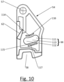
- the shape of the slot 66 is best illustrated in figure 10 which shows a front view of the pawl locking member 54.
- the groove 66 has a specific shape with a narrower central part 113 and larger (compared to the central part 113) end regions 111, 112.
- the narrower central part 113 is caused by inwardly positioned ridges 114, 115. Besides these ridges 114, 115, there is provided a groove or opening 116, 117 in the pawl locking member 54.
- the groove or opening 116, 117 may be formed by a local weakening of the pawl locking member 54 in order to allow the ridges 114, 115 to be displaced outwards due to the pin 67 moving between the end regions 111, 112 upon actuation of the key cylinder 51.
- the ridges 114, 115 are resilient and urge the pin 67 to either one of the end regions 111, 112. As such, the specific shape forms a bi-stable pawl locking member 54.
- the locking mechanism further comprises a pawl 59 that is mounted on the pawl locking member 54. More specifically, the pawl 59 has an opening 60 with the pin 55 also being placed through this opening 60 to mount the pawl 59 to the pawl locking member 54 and the frame 32.
- the pin 55 thus also forms a pivot around which the pawl 59 is able to rotate between a rest position with respect to the pawl locking member 54 (shown in figures 7A, 7C , 8A and 8C ) and a displaced position with respect to the pawl locking member 54 (shown in figures 7B and 8B ).
- the pawl locking member 54 is provided with an abutment 62 which defines the rest position of the pawl 59, i.e.
- a spring 61 is disposed between the pawl locking member 54 and the pawl 59 in order to urge the pawl 59 into its rest position with respect to the pawl locking member 54, i.e. pushing the pawl 59 against the abutment 62.
- the spring 61 is a torsion spring having a first end 61a that engages the pawl locking member 54 and a second end 61b that engages the pawl 59.
- the pawl 59 further comprises an abutment surface 63 against which the top surface 64 of the horizontal plate 39 (which is part of the upper link rod 33) may abut.
- the locking mechanism operates in the following way.
- the pawl 59 is in its rest position with respect to the pawl locking member 54 which itself is located in its first position.
- the abutment surface 63 of the pawl 59 is positioned next to the top surface 64 of the horizontal plate 39 which is part of the upper link rod 33.
- the pawl 59 is in its retracted position and normal operation (i.e. an upwards translation upon pulling the knob 8) of the upper link member 33 is possible as shown in figures 7A and 8A .
- the first position of the pawl locking member 54 is also referred to as the locking position since the pawl 59 is locked in its retracted position with respect to the upper link member 33 and normal operation is allowed.
- Actuating the key cylinder 51 causes a rotation of the rotary driving bit 52 in a locking direction 65 (indicated in figure 8A ) and causes the pawl locking member 54 to be rotated towards its second position.
- the pawl 59 remains stationary with respect to the pawl locking member 54 and thus remains in its rest position.
- the abutment surface 63 of the pawl 59 is positioned above the top surface 64 of the horizontal plate 39 which is part of the upper link rod 33. As such, the pawl 59 is in its extended position and normal operation (i.e.
- the main advantage of the pawl 59 and the pawl locking member 54 is to avoid blocking the knob 8 in the actuated (i.e. upwards) position when the key cylinder 51 is actuated while the knob 8 is kept upwards by the user as illustrated in figures 7B and 8B . More specifically, in case the knob 8 is pulled upwards (i.e. the upper link rod 33 is in an upwards position) and the key cylinder 51 is actuated to move the pawl locking member 54 to its second position, a pawl that is fixed on the pawl locking member 54 would prevent the knob 8 being pulled downwards by gravity to its rest position.
- the downwards motion of the knob 8 and the upper link rod 33 i.e. the horizontal plate 39
- the spring 61 pushes the pawl 59 against the abutment surface 62 on the pawl locking member 54 to its locking position illustrated in figures 7C and 8C .
- the second position of the pawl locking member 54 is also referred to as the release position since the pawl 59 is released and is free to be moved from its extended to its retracted position by the downwards motion of the knob 8.
- the spring 61 may be interposed between the pawl 59 and the frame 62, the pawl 59 and/or the pawl locking member 54 may undergo a translational motion instead of a rotary motion, the pawl 59 and the pawl locking member 54 may be mounted on different rotational axes, the pawl 59 may engage another part of the upper link rod 33, etc.
- the magnetic roles of the latch bolt 14 and the magnet 19 are reversed.
- the latch bolt 14 is a permanent magnet and element 19 is made from a ferromagnetic material (e.g. iron).
- the operation of the magnetic latch assembly 1 remains unaffected because the latch bolt 14 will still be attracted to the element 19 as this is fixedly positioned within the keeper assembly 6.
- the latch bolt 14 and the magnet 19 are permanent magnets and/or electromagnets.
- the latch bolt 14, coupler 15 and latch bolt spring 17 are replaced by a magnetic element fixed to the lower end 34a of the lower link rod 34.
- the keeper assembly 6 is replaced by a latch bolt assembly having a horizontally oriented latch bolt that is biased towards its retracted position and is attracted by the magnetic element fixed to the lower end 34a.
- Such embodiments are disclosed in AU 2009/251007 A1 , AU 2013/206766 A1 , 2014/203446 A1 , AU 2016/201778 A1 , and AU 2018/256525 A1 .
- latch bolt assembly 5 may also be reversed, i.e. the latch bolt assembly 5 may be mounted on the closure member 2 and the keeper assembly 6 on the support 4.
- a second embodiment of a magnetic latch assembly 1' which forms part of the claimed invention will be described with reference to figures 11A to 18 .
- Elements in the magnetic latch assembly 1' will be indicated with the same reference numbers as corresponding elements in the magnetic latch assembly 1.
- the magnetic latch assembly 1' is mounted on a closure system.
- the closure system comprises a closure member 2 that is hinged on a first support 3 and that may be fastened to a second support 4 by means of the magnetic latch assembly 1.
- the closure member 2 is formed by a gate and the supports 3, 4 are formed by fixed 1', but it will be readily appreciated that the magnetic latch assembly 1' is also suitable for other kinds of closure members (e.g. a sliding closure member, a door, etc.) and/or supports.
- the support may be formed by a closure member in case the magnetic latch assembly 1' is used on a double gate.
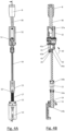
- the magnetic latch assembly 1' generally comprises a latch bolt assembly 5 and a magnetic keeper assembly 6 as shown in figures 11A and 11B .
- the latch bolt assembly 5 is mounted on the closure member 2 and the magnetic keeper assembly 6 is mounted on the support 4, but it will be readily appreciated that these may be reversed.
- the latch bolt assembly 5 comprises a vertically oriented elongated housing 7 with a pull knob 8 protruding from the top thereof.
- the major difference between the magnetic latch assemblies 1, 1' are the components in the bottom part of the housing 7 and underneath the housing 7. More specifically, the magnetic latch assemblies 1, 1' are identical for all upper components in the housing 7, i.e. ell components from the knob 8 downwards to and including the lower link rod 34 are identical and will not be described again.
- the magnetic latch assembly 1 had a vertically oriented latch bolt 14 protruding from the bottom of the housing 7 and an L-shaped bracket 10 underneath the elongated housing 7, the magnetic latch assembly 1' is provided with a second housing 70 underneath the elongated housing 7 in which a horizontally oriented latch bolt 14 is placed.
- the latch bolt 14 is moveable along a horizontal translational motion between a retracted position (shown in figure 14A ) and a latching position (shown in figure 14B ) in which the latch bolt 14 protrudes from the side wall 72 of the housing 70.
- the elongated housing 7 and the bottom housing 70 together may be regarded as a frame on which the various components of the latch bolt assembly are mounted.
- the magnetic latch assembly 1' Due to the horizontal placement of the latch bolt 14, the magnetic latch assembly 1' has different configurations for a right-handed closure member 2 (shown in figures 11A and 12A ) and for a left-handed closure member 2 (shown in figures 11B and 12B ). More specifically, the elongated housing 70 is always fixed in the same position with respect to the closure member 2, while the lower housing 70 together with its internal components is rotatable over 180° about the vertical direction 15 with respect to the elongated housing 7 as described in more detail below by reference to figures 16 to 18 . In this way, the side wall 72 from which the latch bolt 14 protrudes in its latched state is differently positioned with respect to the elongated housing 7 depending on the handedness of the closure member 2. The lower housing 70 positioning is done prior to mounting the latch bolt assembly 5 on the closure member 2.
- the latch bolt assembly 5 is mounted on the closure member 2 as best illustrated in figures 12A and 12B .
- the latch bolt assembly 5 is mounted on the closure member 2 by means of an upper L-shaped mounting bracket 73 and a lower L-shaped mounting bracket 74.
- the L-shaped mounting brackets 73, 74 have a first leg 73a, 74a that is fixed by a bolt 75 to the side of the closure member 2 and a second leg 73b, 74b on which two guide rails 76 are provided.
- the frame 7, 70 has corresponding guides that fit in the guide rails 76 to allow mounting the latch bolt assembly 5 by sliding it along the vertical direction 15.
- the elongated housing 7 is provided with corresponding guides 112 (shown in figures 17A and 17B ) in its rear wall, while the housing 70 has corresponding guides 77 on both its front and rear side (i.e. the front and rear side are symmetrical), which sides change positions depending on the handedness of the closure member 2.
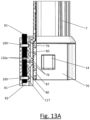
- the second leg 74b of the lower L-shaped bracket 74 is provided with two projections 78 that fit into one of a set of parallel grooves 79 provided on the housing 70. This is shown in detail in figures 13A and 19 .
- the projections 78 are mounted on arms 80 that form part of a fixation element 118 that is fixed to the second leg 74b of the L-shaped bracket 74. More specifically, the fixation element 118 fits in the guides 76 on the second leg 74b of the L-shaped bracket 74 so that the fixation element 118 is fixed in the horizontal plane (i.e. the width direction 46 and the depth direction 38) with respect to the L-shaped bracket 74.
- a vertical displacement of the fixation element 118 with respect to the L-shaped bracket 74 is avoided by the square nut elements 100 which are inserted through corresponding openings 119 in the second leg 74b into corresponding grooves (best shown in figure 13A ) in the fixation element 118.
- a through-hole 82 that extends in the vertical direction 15 is present between the fixation element 118 and the second leg 74b of the L-shaped bracket 74 the L-shaped bracket 74.
- Two set screws 81 are provided in the through-hole 82 which extend through a corresponding square nut element 100, each set screw 81 being individually adjustable (e.g. by using a hex key or the like).
- the L-shaped bracket 74 is usually made from metal (e.g.
- fixation element 118 is usually injection moulded from a polymeric material (e.g. polyamide, in particular fibre-reinforced polyamide, or the like).
- polymeric material e.g. polyamide, in particular fibre-reinforced polyamide, or the like.
- the square nut elements 118 also ensure that any vertical forces exerted on the fixation element 118 (i.e. on the projections 78) are directly transmitted to the metal L-shaped bracket 74.
- each protrusion 78 interlocks with a groove from the parallel grooves 79 thus preventing a further vertical motion of the housing 70 with respect to the lower L-shaped bracket 74.
- the vertical position of the latch bolt assembly 5 with respect to the closure member 2 is fixed.
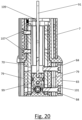
- the vertical position of the latch bolt assembly 5 with respect to the closure member 2 may be adjusted by loosening (one or both of) the set screws 81 and moving the frame 7, 70 before again fastening the set screws 81. Due to the different possible rotational positions of the lower housing 70 with respect to the elongated housing 7, grooves 79 are provided on both sides of the lower housing 70 as shown in figure 20 .
- the use of two set screws 81 and two projections 78 is beneficial as it allows to operate the adjustment mechanism from either the upper side or the lower side of the lower L-shaped bracket 74.
- This is particularly advantageous since the lower L-shaped bracket 74 is mounted in two different vertical orientations depending on the handedness of the closure member 2 since the first leg 74a of the lower L-shaped bracket 74 is to be positioned between the closure member 2 and the support 4.
- the latch bolt assembly 5 is placed on the L-shaped brackets 73, 74, it is very difficult to reach and rotate the upper set screw 81.
- only one of the set screws 81 i.e.
- the lower one is rotated to cause the protrusions 78 to engage the grooves 79.
- the use of two projections 78 provides a stronger connection when compared to a single projection 78.
- Two arms 80 is also beneficial as this results in a latch bolt assembly 5 that is always hanging from one arm (i.e. the upper one) and pushing on the other arm (i.e. the lower one), while, in case of only a single arm, the latch bolt assembly 5 is either hanging or pushing depending on the orientation.
- the arms 80 may be prone to elongation or compression which could result in a shift in height.
- a stop is provided to limit movement of the set screws 81. More specifically, of the two set screws 81, one is stationary and the other one is being rotated to fix the height (which one depends on the vertical orientation of the L-shaped bracket 74). As such, the stationary set screw will act as a stop for the rotatable set screw as the opposing end faces 126a engage one another. Another advantage of this is that, as the end faces 126a engage one another, a further rotation of one of the set screws 81 urges the nut elements 100 away from one another causing them to be very robustly locked into the openings 119.
- the fixation element 118 is integrally formed with the L-shaped bracket 74.
- such an element is not easily injection moulded.
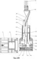
- Figure 13B illustrates a variation of the height adjustment mechanism shown in figure 13A . More specifically, the two set screws are replaced by means of a single elongated partially threaded rod 81 which is rotatable from either end 81a, 81b (e.g. by means of a hex key or the like). The upper end 81b of the threaded rod 81 is accessible via opening 82.
- the fixation element 118 further comprises a stop 127 near its top which prevents the threaded rod 81 from being rotated too far (the stop could also be formed by an additional bolt, pin or the like to fix the threaded rod in its position after rotation).
- the threaded rod 81 is connected to the L-shaped bracket 74 by means of a single rectangular nut 100.
- the two arms are replaced by a single continuous arm 80 which is fixed to the fixation element 118 at both ends and has a single central protrusion 79.
- the continuous arm 80 is flexible and can be bent away from the L-shaped bracket 74.
- the threaded rod comprises a central area 126 with a decreased diameter which corresponds to the location of the protrusion 79. B rotating the threaded rod 81, the decreased diameter part 126 moves upwards so that the lower wall 126a engages the protrusion urging the protrusion towards the grooves 79.
- the housing 70 is also provided with a stop 83 that is mounted on the front side of the housing 70.
- the stop 83 includes guides 85 corresponding to the guides 77 on the housing 70, which guides 77 are used to engage the lower L-shaped bracket 74.
- the stop 83 is slid upwards and is fixed by means of bolts 84 that extend through openings 86 in the stop 83 and fit in holes 87 in the housing 70.
- the puller 88 and is moveable by a vertical translational motion between a rest position (shown in figures 14A and 14C ) and an actuated position (shown in figure 14B ). These positions are directly related to the position of the knob 8, i.e. when the knob 8 is in its rest position, the puller 88 is in its rest position and vice versa.
- the puller 88 has a bevelled surface 89, the function of which is described below.
- the latch bolt 14 is positioned horizontally and is moveable between a retracted position (shown in figures 14B and 14C ) and a latching position (shown in figure 14A ).
- a latch bolt spring 17 is positioned between the housing 70 and the latch bolt 14 in order to urge the latch bolt 14 towards its retracted position.
- the inner end 14a of the latch bolt 14 is provided with a protrusion 90 which engages one end of the latch bolt spring 17.
- On the protrusion 90 there is provided a guiding pin 104 around which the latch bolt spring 17 is positioned. This guiding pin 104 prevents the latch bolt spring 17 from buckling.
- the latch bolt spring 17 is thus a compression spring in the illustrated embodiment.
- the keeper assembly 6 is provided with a magnet 19 which magnetically attracts the latch bolt 14 to move the latch bolt 14 against the latch bolt spring 17 towards its latching position.
- the latch bolt 14 is mounted to (more specifically suspended from) the housing 70 by means of two levers, namely an operation lever 91 and a support lever 92.
- the operation lever 91 is pivotally connected to the housing 70 in a central area 91a by a transversely positioned pin 93 and is pivotally connected at its lower end 91b to the latch bolt 14 by another transversely positioned pin 94.
- the support lever 92 is fastened in a similar way at its upper end 92a to the frame by pin 95 and at its lower end 92b to the latch bolt 14 by pin 96. No other guiding and/or support means are required for the latch bolt 14, such that the latch bolt 14 is able to move with nearly no friction.
- the upper end 91c of the operation lever 91 is provided with a transverse pin 97 which engages the puller 88, in particular the bevelled surface 89 thereof.
- the levers 91, 92 are rotatable about their respective pivot pins 93, 95 between a first position (in which the latch bolt 14 is in its retracted position) and a second position (in which the latch bolt 14 is in its latching position). It will be readily appreciated that the levers 91, 92 may also be used as a latch bolt biasing means instead of and/or additional to the latch bolt spring 17. More specifically, the levers 91, 92 may be designed in order to automatically return to their rest position in which the latch bolt 14 is in its retracted state. As shown in figures 14A to 14C , the latch bolt 14 does not engage the housing 70 in the vertical direction, thus reducing friction.
- plastic rings 105, 106 are disposed between the levers 91, 92 and the latch bolt 14. More specifically, a plastic ring 105 is disposed between the transverse pin 94 and the latch bolt core 101 and a plastic ring 106 is disposed between the transverse pin 96 and the latch bolt core 101.
- the latch bolt core 101 (indicated in figure 15 ) could be made from a plastic material.
- the latch bolt 14 has a ferromagnetic element 98 that may be attracted by the magnet 19.
- the ferromagnetic element 98 is preferably located as near to the magnet 19 as possible and is therefore located at the front 14b of the latch bolt 14.
- a protective surface coating (not shown) is applied to the ferromagnetic element 98 in order to avoid oxidization of the ferromagnetic element 98.
- such coatings are easily damaged due to friction.
- the ferromagnetic element 98 is flanked by two protective plates 99 that are made from stainless steel or other suitable materials. This avoids sideways damage to the ferromagnetic element 98 in case a sideways force is exerted on the closure member 2 when the latch bolt 14 is in its latched position.
- Figure 15 further illustrates that the latch bolt 14, at least the protective plates 99, slide along the housing 70.
- the housing 70 has a central hole (not indicated) in which the latch bolt 14 is suspended. This is beneficial in case the latch bolt 14 is in its latching position within the keeper assembly 6 and a user attempts to force open the closure member 2. More specifically, trying to open the closure member 2 causes the latch bolt 14 to be pushed against the keeper assembly 6 in the width direction (i.e. downwards in figure 15 ). This sideways force on the latch bolt 14 is then directly transferred (via the protective plates 99) to the housing 70 thus avoiding that the force would be exerted on the levers 91, 92.
- the latch bolt 14 has a rectangular (in particular square) cross section and is disposed in a square opening in the housing 70. In this way, a rotation of the latch bolt 14 around its longitudinal axis is prevented or at least the forces associated therewith are transferred directly to the housing 70 and are not exerted on the levers 91, 92.
- no coupler 15 is present in the magnetic latch assembly 1'.
- the same functionality i.e. allowing the knob 8 to be in its rest position with the latch bolt 14 in its retracted position
- the puller 88 does not engage the operation lever 91 or the support lever 92 irrespective of the position of the puller 88.
- the puller 88 is free to move from its actuated state (shown in figure 14B ) to its rest state (shown in figure 14C ) without engaging the levers 91, 92.
- FIG. 14A shows the latch bolt 14 in its latching position due to the magnetic attraction from the magnet 19 in the magnetic keep assembly 6.
- the user pulls the knob 8 upwards from its rest position to its actuated position thereby pulling (through the upper and lower link rods 33, 34) the puller 88 upwards from its rest position to its actuated position.
- the bevelled surface 89 engages the pin 97 thereby pushing the upper end 91c of the operation lever 91 in the width direction 46 in a first sense and likewise pushing the lower end 91b of the operation lever 91 in the width direction 46 in a second sense which is opposite to the first sense.
- the operation lever 91 acts as a seesaw about its central fixed pivot 93 and the puller 88 with the bevelled surface 89 acts as a sliding cam with the upper end 91c of the operation lever 91 being the cam follower.
- This pulls the latch bolt 14 into its retracted position i.e. the latch bolt 14 undergoes a horizontal translational motion
- the closure member 2 is unfastened and the user may open the closure member 2 and the knob 8 may be let go. Gravity will cause the knob 8 and the puller 88 to fall downwards to their rest position as shown in figure 14C .
- the latch bolt 14 remains in its retracted position due to the latch bolt spring 17 and the pin 97 does not engage the bevelled surface 89.
- the inclination of the bevelled surface determines the force required to operate the puller 88. More specifically, the larger the inclination (with respect to the vertical direction 15), the more force a user will have to exert when pulling the actuator 8 upwards. However, the travel path is shorter. A smaller inclination has the opposite effect, i.e. a longer travel path with a decreased force to be exerted.
- the operation lever 91 acts as a first-order lever with the pin 93 forming the fixed pivot, the puller 88 being the effort and the latch bolt 14 being the load.
- the operation lever 91 may pivot about its upper end (like the support lever 83) with the puller 88 engaging a central part of the operation lever.
- the operation lever 91 may also be a third-order lever.
- the operation lever 91 may also be a second-order lever.
- a first-order lever is preferred since this allows a flexible adaptation between force-reduction or force-magnification depending on the magnetic attraction and the desired actuation force.
- the first-order lever also allows varying the displacement by the angle made between the first leg 91d and the second leg 91e of the operation lever 91 additional to variations possible by the lengths of the legs 91d, 91e.
- the operation lever 91 and the support lever 92 also limit the horizontal motion of the latch bolt 14. More specifically, in the latching position of the latch bolt 14 (see figure 14A ), the lower arm 91e of the operation lever 91 abuts against the housing 70, while, in the retracted position of the latch bolt 14 (see figures 14B and 14C ), the support lever 92 abuts against the housing 70.
- the distance between the pivot points 93, 95 of the levers 91, 92 is substantially the same as the distance between the latch bolt engagement locations 94, 96.
- the levers 91, 92 are connected to the latch bolt 14 at different locations along the length of the latch bolt 14. The distance between these locations is preferably as large as possible to increase stability.
- the levers 91, 92 are bent away from one another.
- Figures 16 to 18 illustrate more details on the coupling between the puller 88 and the lower link rod 34 and on the coupling between the housings 7, 70.
- the elongated housing 70 is always fixed in the same position with respect to the closure member 2, while the lower housing 70 together with its internal components is rotatable over 180° about the vertical direction 15 with respect to the elongated housing 7.
- one or more (two in the illustrated embodiment) screws 107 are screwed through the housing 7 and the housing 70 (in particular the shaft 108) as best shown in figure 20 thereby preventing rotation of the lower housing 70.
- the latch assembly 5 is mounted to the closure system, in particular by sliding it downwards from above the L-shaped brackets 73, 74 with the guides 76 of the brackets 73, 74 engaging the guides 77, 112 on the housings 70, 7, which guides 77, 112 are thus preferably continuous with one another.
- the top side 108 of the lower housing 70 forms a substantially cylindrical shaft 111 about which the elongated housing 7 is positioned.
- a fixation bolt 109 is fixed to the top of the shaft 108.
- the elongated housing 7 comprises an inner collar 110 against which the shaft 108 abuts on one side and the head of the fixation bolt 109 on the other. More specifically, the inner collar 110 has a top side 113 and a bottom side 114 (both indicated in figure 14C ).
- the shaft 108 (which is part of the housing 70) abuts against the bottom side 114 of the inner collar 110 as shown in figure 14C , while the fixation bolt 109 abuts against the top side 113 of the inner collar 110 as shown in figures 17A and 17B .
- the fixation bolt 109 ensures that the housing 70 is fixed with respect to the elongated housing 7 in the vertical direction 15 thus avoiding that these elements 7, 70 are detached from one another.
- the top of the shaft 111 is also provide with a vertical protrusion 115 adj acent the fixation bolt 109.
- the inner collar 110 extends over about 270° of the elongated housing 7 thus limiting the motion of the fixation bolt 109 and the vertical protrusion 115, i.e. of the lower housing 70. More specifically, in a first orientation shown in figure 17A , the fixation bolt 109 engages a first abutment 110a which forms one end of the inner collar 110, while, in second orientation shown in figure 17B , the vertical protrusion 115 engages a second abutment 110b which forms another end of the inner collar 110.
- the vertical protrusion 115 is not present and the fixation bolt 109 abuts against both ends of the inner collar 110 depending on the orientation of the housing 70.
- the puller 88 rotates together with the housing 70, the puller 88 is also rotatable about the lower link rod 34 since the lower link rod 34 is fixed to the elongated housing 7. This is best shown in figure 18 where the top part 88a of the puller 88 is rotatable about the bottom part 34b of the lower link rod 34.
- An assembly opening 116 is provided in the top part 88a of the puller 88 to allow assembly of the lower link rod 34 and the puller 88.
- the magnet 19 in the magnet latch assembly 1' is identical to that in the magnet latch assembly 1 and similar forces are exerted on the latch bolt 14 with similar forces being required in order to lift the knob 8.
- the magnetic roles of the latch bolt 14 and the magnet 19 are reversed.
- the latch bolt 14 is a permanent magnet and element 19 is made from a ferromagnetic material (e.g. iron).
- the operation of the magnetic latch assembly 1 remains unaffected because the latch bolt 14 will still be attracted to the element 19 as this is fixedly positioned within the keeper assembly 6.
- latch bolt 14 and the magnet 19 are permanent magnets and/or electromagnets.
- the position of the latch bolt assembly 5 and the keeper assembly 6 may also be reversed, i.e. the latch bolt assembly 5 may be mounted on the closure member 2 and the keeper assembly 6 on the support 4.
- the latch bolt 14 and the magnet 19 are oriented in such a way that the attraction force is in the same orientation as the unlocking movement. More specifically, in the magnetic latch 1, the latch bolt 14 is vertically attracted to the magnet 19 and is unfastened by moving the latch bolt 14 upwards in the vertical direction. While, in the magnetic latch 1', the latch bolt 14 is horizontally attracted to the magnet 19 and is unfastened by moving the latch bolt 14 away in the horizontal direction.
- the low-friction latch bolt 14 (i.e. the latch bolt 14 mounted to the housing 70 by means of two levers 91, 92) may also be used in less complex magnetic latch assemblies.
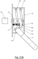
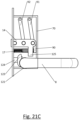
- An example of such a magnetic latch bolt assembly embodiment is illustrated in figures 21A to 21C .
- the magnetic latch bolt assembly comprises a housing 70 in which a latch bolt 14 is suspended by means of two levers 91, 92. More specifically, the levers 91, 92 are pivotally connected to the frame by transverse pins 93, 95 and to the latch bolt 14 by transverse pins 94, 96.
- a latch bolt spring 17 i.e. a compression spring
- a guiding pin 104 is provided for preventing buckling of the latch bolt spring 17.
- the latch bolt spring 17 urges the latch bolt 14 towards its unlatching position (shown in figure 21C ).
- the latch bolt assembly further comprises a follower 121 designed to cooperate with a spindle (not shown) which is connected to a door handle 8 or the like, i.e. an actuator.
- the follower 121 includes a rotary driving bit 123 which engages the latch bolt 14, in particular a protrusion 125 thereon.
- a biasing member biases the follower 121 towards its rest position shown in figure 21C where the rotary driving bit 123 engages a stop 124 provided on the frame 70, although other means are known to limit movement of the follower 121.
- the latch bolt 14 In the rest position of the magnetic latch bolt assembly (shown in figure 21C ), the latch bolt 14 is retracted due to the latch bolt spring 17.
- the door handle 8 i.e. the actuator
- the latch bolt 14 When the closure member on which the magnetic latch bolt assembly is mounted is closed, the latch bolt 14 is attracted by magnet 19 towards its projecting position (shown in figure 21A ). The roles of the magnetic elements 14, 19 may naturally be reversed.
- actuating the door handle 8 i.e. the actuator
- the actuator may also be in the form of a push-bar or panic-bar.
- a main advantage of this kind of magnetic latch assembly is that there is no need to have a latch bolt with an inclined front surface which, when closing a closure member into which or on which the latch bolt assembly is mounted, cooperates with a striker (not shown) to move the latch bolt 14 to the retracted position.
- a striker not shown
- the closure member has to close with a sufficiently large force. In the present embodiment, this is no longer required as the rest position of the latch bolt is the retracted position thus always allowing the closure member to be closed even with a minimal closing speed.
- This latch bolt assembly also illustrates that the levers 91, 92 are not necessarily part of the latch bolt operating mechanism.
- the levers 91, 92 may be used solely for suspending the latch bolt, while the operating mechanism is distinct therefrom.
- the operation lever 91 in the magnetic latch 1' in a non-illustrated embodiment, does not necessarily form part of the latch bolt operating mechanism and a different construction is possible where the puller 88 directly or indirectly engages the latch bolt 14 without required in the operation lever 91.
Landscapes
- Engineering & Computer Science (AREA)
- Mechanical Engineering (AREA)
- Physics & Mathematics (AREA)
- Electromagnetism (AREA)
- Structural Engineering (AREA)
- Lock And Its Accessories (AREA)
Claims (15)
- Loquet magnétique (1') pour fixer un élément de fermeture à un support, le loquet magnétique comprenant un ensemble de pêne demi-tour (5) configuré pour être monté sur un élément de fermeture (2) et le support (4) et un ensemble gâche (6) configuré pour être monté sur l'autre élément parmi l'élément de fermeture et le support, l'ensemble gâche comprenant un premier élément magnétique (19) et l'ensemble de pêne demi-tour comprenant :- un premier boîtier allongé (7) s'étendant le long d'une direction verticale (15), le premier boîtier ayant un côté avant et un côté arrière et étant configuré pour être monté avec son côté arrière faisant face audit un élément parmi l'élément de fermeture et le support ;- un pêne demi-tour (14) pouvant être déplacé entre une position de verrouillage et une position rétractée, le pêne demi-tour comprenant un second élément magnétique (98), dans lequel le premier élément magnétique et le second élément magnétique sont configurés pour s'attirer magnétiquement l'un l'autre afin de déplacer le pêne demi-tour dans sa position de verrouillage ; et- un mécanisme de fonctionnement de pêne demi-tour comprenant un actionneur (8) monté sur le dessus du premier boîtier, le mécanisme de fonctionnement de pêne demi-tour étant configuré pour, sur actionnement de l'actionneur, déplacer le pêne demi-tour de sa position de verrouillage à sa position rétractée contre l'attraction magnétique entre ledit premier et ledit second élément magnétique,caractérisé en ce que l'ensemble de pêne demi-tour comprend en outre un second boîtier (70) relié au premier boîtier et positionné sous celui-ci, le second boîtier ayant une face latérale, dans lequel le second boîtier pouvant tourner par rapport au premier boîtier autour de la direction verticale entre une première position de rotation dans laquelle l'ensemble de pêne demi-tour est utilisable pour un élément de fermeture à droite et une seconde position de rotation dans laquelle l'ensemble de pêne demi-tour est utilisable pour un élément de fermeture à gauche, le pêne demi-tour est monté dans le second boîtier et peut être déplacé entre sa position de verrouillage et sa position rétractée le long d'une direction horizontale, dans lequel le pêne demi-tour en position de verrouillage s'étendant à partir de la face latérale du second boîtier.
- Loquet magnétique selon la revendication 1, caractérisé en ce qu'un élément parmi le premier boîtier et le second boîtier comprend un arbre (108) s'étendant dans la direction verticale et ayant une face d'extrémité, l'autre élément parmi le premier boîtier et le second boîtier comprenant une partie creuse correspondante qui est montée de manière rotative sur l'arbre.
- Loquet magnétique selon la revendication 2, caractérisé en ce que ladite partie creuse correspondante comprend un collier intérieur (110) ayant une surface de butée (113), l'ensemble de pêne demi-tour comprenant en outre un élément de fixation (109) monté sur la face d'extrémité de l'arbre et s'engageant axialement dans la direction verticale sur la surface de butée.
- Loquet magnétique selon la revendication 2 ou 3, caractérisé en ce que le second boîtier comprend une autre surface de butée, ladite partie creuse comprenant une face d'extrémité qui s'engage axialement dans l'autre surface de butée.
- Loquet magnétique selon l'une quelconque des revendications précédentes, caractérisé en ce qu'un élément parmi le premier boîtier et le second boîtier comprend un premier arrêt (110a) et un second arrêt (110b), l'autre élément parmi le premier boîtier et le second boîtier comprenant une saillie (115) qui s'engage dans le premier arrêt lorsque le second boîtier est dans sa première position de rotation et qui s'engage dans le second arrêt lorsque le second boîtier est dans sa seconde position de rotation.
- Loquet magnétique selon l'une quelconque des revendications précédentes, caractérisé en ce que le second boîtier comprend deux faces opposées adjacentes à la face latérale, les deux faces opposées étant symétriques l'une par rapport à l'autre.
- Loquet magnétique selon la revendication 6, caractérisé en ce que chacun de ces côtés opposés comprend des moyens de couplage identiques (77)
- Loquet magnétique selon la revendication 7, caractérisé en ce que l'ensemble de pêne demi-tour comprend en outre un arrêt (83) monté, à l'aide des moyens de couplage, sur un premier desdits deux côtés opposés lorsque le second boîtier est dans sa première position de rotation et sur un second desdits deux côtés opposés lorsque le second boîtier est dans sa seconde position de rotation.
- Loquet magnétique selon la revendication 7 ou 8, caractérisé en ce que d'autres moyens de couplage (121) sont pourvus sur la face arrière du premier boîtier, lesquels moyens de couplage supplémentaires sont continus avec lesdits moyens de couplage sur les côtés opposés du second boîtier.
- Loquet magnétique selon l'une quelconque des revendications 7 à 9, caractérisé en ce que les moyens de couplage et/ou les moyens de couplage supplémentaires comprennent un guide configuré pour être monté sur un élément de montage correspondant sur ledit élément parmi l'élément de fermeture et le support.
- Loquet magnétique selon l'une quelconque des revendications précédentes, caractérisé en ce que l'ensemble de loquet comprend en outre un élément de fixation amovible (107) pour fixer le second boîtier au premier boîtier dans l'une ou l'autre de sa première et sa seconde position de rotation.
- Loquet magnétique selon l'une quelconque des revendications précédentes, caractérisé en ce que le second boîtier est rotatif par rapport au premier boîtier autour de la direction verticale entre la première position de rotation et la seconde position de rotation sur un angle compris entre 140° et 220° et notamment entre 170° et 190°, cet angle étant plus particulièrement de l'ordre de 180°.
- Loquet magnétique selon l'une quelconque des revendications précédentes, caractérisé en ce que le mécanisme de fonctionnement de pêne demi-tour comprend :- une tige de liaison (34) s'étendant verticalement, montée dans le premier boîtier et ayant une extrémité inférieure (34b), la tige de liaison s'étendant verticalement pouvant coulisser dans la direction verticale d'une position de repos à une position actionnée lors de l'actionnement de l'actionneur ;- une came coulissante (88) reliée à l'extrémité inférieure de la tige de liaison et pouvant être déplacée par un mouvement de translation dans une direction verticale (15) d'une première position à une seconde position ; et- un levier suiveur (91) relié de manière pivotante au second boîtier et connecté au pêne demi-tour, la came coulissante s'engageant dans le levier suiveur pour déplacer le levier suiveur d'une position de repos à une position actionnée lors de l'actionnement de l'actionneur, faisant ainsi glisser le pêne demi-tour de sa position de verrouillage à sa position rétractée,dans lequel la came coulissante est rotative par rapport à la tige de liaison autour de la direction verticale, en particulier sur un angle compris entre 140° et 220° et plus particulièrement entre 170° et 190°, cet angle étant plus particulièrement d'environ 180°.
- Loquet magnétique selon l'une quelconque des revendications précédentes, caractérisé en ce que l'ensemble de pêne demi-tour comprend un élément de sollicitation de pêne demi-tour (17) conçu pour pousser le pêne demi-tour dans sa position rétractée.
- Procédé de montage de l'ensemble de pêne demi-tour du loquet magnétique selon l'une quelconque des revendications précédentes sur un élément parmi l'élément de fermeture et le support, le procédé comprenant:- faire tourner le second boîtier dans sa première et sa seconde position de rotation ;- fixer le second boîtier dans ladite une position parmi sa première et sa seconde position de rotation, notamment en fixant un élément de fixation amovible ;- monter le premier boîtier allongé et/ou le second boîtier sur ledit un élément parmi l'élément de fermeture et le support ; et- éventuellement, fixer un arrêt sur la face avant du second boîtier.
Applications Claiming Priority (1)
| Application Number | Priority Date | Filing Date | Title |
|---|---|---|---|
| EP20211973.1A EP4008867A1 (fr) | 2020-12-04 | 2020-12-04 | Loquet magnétique pour fixer un élément de fermeture à charnière à un support |
Publications (3)
| Publication Number | Publication Date |
|---|---|
| EP4008868A1 EP4008868A1 (fr) | 2022-06-08 |
| EP4008868C0 EP4008868C0 (fr) | 2023-11-08 |
| EP4008868B1 true EP4008868B1 (fr) | 2023-11-08 |
Family
ID=73726710
Family Applications (2)
| Application Number | Title | Priority Date | Filing Date |
|---|---|---|---|
| EP20211973.1A Withdrawn EP4008867A1 (fr) | 2020-12-04 | 2020-12-04 | Loquet magnétique pour fixer un élément de fermeture à charnière à un support |
| EP21212386.3A Active EP4008868B1 (fr) | 2020-12-04 | 2021-12-03 | Loquet magnétique pour fixer un élément de fermeture à charnière à un support |
Family Applications Before (1)
| Application Number | Title | Priority Date | Filing Date |
|---|---|---|---|
| EP20211973.1A Withdrawn EP4008867A1 (fr) | 2020-12-04 | 2020-12-04 | Loquet magnétique pour fixer un élément de fermeture à charnière à un support |
Country Status (3)
| Country | Link |
|---|---|
| US (1) | US11795744B2 (fr) |
| EP (2) | EP4008867A1 (fr) |
| AU (1) | AU2021277755A1 (fr) |
Families Citing this family (4)
| Publication number | Priority date | Publication date | Assignee | Title |
|---|---|---|---|---|
| CN212394434U (zh) * | 2019-11-23 | 2021-01-26 | 中童(厦门)婴童智能家居有限公司 | 一种应用于游戏床上的升降装置 |
| PL3995658T3 (pl) * | 2020-11-06 | 2024-03-18 | Locinox | Zatrzask magnetyczny do mocowania zawiasowego członu zamykającego do wspornika |
| US20230275444A1 (en) * | 2022-02-25 | 2023-08-31 | Milwaukee Electric Tool Corporation | Magnet coupling assembly |
| USD1114590S1 (en) * | 2023-05-30 | 2026-02-24 | D & D Group Pty Ltd | Latch actuator |
Family Cites Families (28)
| Publication number | Priority date | Publication date | Assignee | Title |
|---|---|---|---|---|
| US3736016A (en) * | 1971-12-06 | 1973-05-29 | C G Garvey | Lock guard for trailer doors |
| US5362116A (en) * | 1990-08-13 | 1994-11-08 | David Doyle | Self latching magnetic latching device |
| US5133581A (en) * | 1991-08-26 | 1992-07-28 | Von Duprin, Inc. | Electromagnetic lock assembly |
| AUPS039102A0 (en) | 2002-02-08 | 2002-02-28 | D & D Group Pty Limited | Improved magnetic latching device |
| US9790708B2 (en) * | 2004-02-24 | 2017-10-17 | D & D Group Pty. Ltd. | Magnetic latch |
| CN1661189B (zh) * | 2004-02-24 | 2010-12-15 | D&D集团有限公司 | 自闭锁磁性闭锁机构 |
| US20050210938A1 (en) | 2004-03-24 | 2005-09-29 | David Doyle | Developments for magnetic latches |
| US7044511B2 (en) * | 2004-04-12 | 2006-05-16 | Nationwide Industries | Magnetic latch system |
| EP1657382A1 (fr) | 2004-11-15 | 2006-05-17 | Joseph Talpe | Dispositif à verrouillage automatique pour verrouiller un elément de fermeture à charnière |
| GB2439477B (en) * | 2005-05-29 | 2008-09-10 | Southco | Electromechanical push to close latch |
| NL1033780C2 (nl) * | 2007-04-27 | 2008-10-28 | Lips Nederland B V | Slot. |
| US8256806B2 (en) * | 2009-03-24 | 2012-09-04 | Nationwide Industries, Inc. | Dual cam magnetic latch system |
| AU2009251007A1 (en) * | 2009-12-18 | 2011-07-07 | Audrius Macernis | Latch |
| WO2011088496A1 (fr) * | 2010-01-22 | 2011-07-28 | Stuart John Andrews | Ensemble de verrouillage |
| US8376421B2 (en) * | 2010-02-08 | 2013-02-19 | Nationwide Industries, Inc. | Magnetic gate latch device |
| EP2476831B1 (fr) * | 2011-01-12 | 2014-03-26 | Joseph Talpe | Dispositif de verrouillage à pêne coulissant |
| PL2749720T3 (pl) * | 2012-12-27 | 2018-10-31 | Joseph Talpe | Elektryczne urządzenie ryglujące z zabezpieczonym przed uszkodzeniem odblokowywaniem awaryjnym |
| US9455188B2 (en) | 2013-01-18 | 2016-09-27 | Globalfoundries Inc. | Through silicon via device having low stress, thin film gaps and methods for forming the same |
| AU2013202689B2 (en) | 2013-02-20 | 2016-09-15 | D & D Technologies Pty Ltd | Latching Assembly |
| AU2013202619B2 (en) | 2013-02-20 | 2017-06-22 | D & D Technologies Pty Ltd | Sensor Configuration for a Latching Assembly |
| AU2013202672A1 (en) | 2013-02-20 | 2014-09-04 | D & D Group Pty Ltd | Latch assembly |
| AU2013206766B2 (en) | 2013-07-09 | 2015-07-09 | Safetech IP Pty Ltd | Improved safety, self-latching, magnetic gate latch device |
| US11131122B2 (en) * | 2013-07-09 | 2021-09-28 | Audrius Macernis | Safety, self-latching, magnetic gate latch device |
| AU2014203446B2 (en) | 2014-06-24 | 2016-07-07 | Safetech IP Pty Ltd | Improved safety, self-latching, magnetic gate latch device |
| US20160060924A1 (en) * | 2014-09-03 | 2016-03-03 | Manjit Singh | Magnetic gate latch |
| AU2016201778B2 (en) | 2016-03-21 | 2018-11-08 | Safetech IP Pty Ltd | Self-latching anti-lock latch device |
| US10641021B2 (en) * | 2016-09-30 | 2020-05-05 | Barrette Outdoor Living, Inc. | Magnetic safety gate latch |
| AU2018256525B2 (en) | 2018-09-27 | 2025-09-11 | Safetech IP Pty Ltd | Latches |
-
2020
- 2020-12-04 EP EP20211973.1A patent/EP4008867A1/fr not_active Withdrawn
-
2021
- 2021-12-03 EP EP21212386.3A patent/EP4008868B1/fr active Active
- 2021-12-03 AU AU2021277755A patent/AU2021277755A1/en not_active Abandoned
- 2021-12-03 US US17/541,460 patent/US11795744B2/en active Active
Also Published As
| Publication number | Publication date |
|---|---|
| EP4008868A1 (fr) | 2022-06-08 |
| US11795744B2 (en) | 2023-10-24 |
| AU2021277755A1 (en) | 2022-06-23 |
| EP4008868C0 (fr) | 2023-11-08 |
| EP4008867A1 (fr) | 2022-06-08 |
| US20220178182A1 (en) | 2022-06-09 |
Similar Documents
| Publication | Publication Date | Title |
|---|---|---|
| EP4008868B1 (fr) | Loquet magnétique pour fixer un élément de fermeture à charnière à un support | |
| EP3995658B1 (fr) | Loquet magnétique pour fixer un élément de fermeture à charnière à un support | |
| EP3995659A1 (fr) | Loquet magnétique pour fixer un élément de fermeture à charnière à un support | |
| US5906403A (en) | Multipoint lock for sliding patio door | |
| US20050210938A1 (en) | Developments for magnetic latches | |
| CA3052497A1 (fr) | Ensemble verrou a pene dormant a deploiement automatique | |
| US12203302B2 (en) | Magnetic latch for fastening a hinged closure member to a support | |
| EP3109381B1 (fr) | Gâche électrique | |
| EP1788169B1 (fr) | Gâche électrique | |
| NZ538074A (en) | Door locking mechanism | |
| AU2021221527A1 (en) | Magnetic Door Latch and Lock Mechanisms | |
| EP4008860A1 (fr) | Ensemble de montage | |
| US8827324B2 (en) | Multi-point lock assembly | |
| KR200452304Y1 (ko) | 고정후크가 마련된 도어록 장치 | |
| KR100875296B1 (ko) | 모티스 락용 래치 볼트 및 이를 구비한 모티스 락 | |
| AU2023222946B2 (en) | Lock with securable retainer for sliding panels and installation method | |
| JP7589990B2 (ja) | 扉開閉装置 | |
| KR200419785Y1 (ko) | 미닫이문의 잠금장치 | |
| AU2019200209B2 (en) | Lock box | |
| WO1994028276A1 (fr) | Pene de verrouillage automatique | |
| AU701778B2 (en) | Lock for sliding door | |
| AU701778C (en) | Lock for sliding door | |
| AU2005201178A1 (en) | Developments for magnetic latches |
Legal Events
| Date | Code | Title | Description |
|---|---|---|---|
| PUAI | Public reference made under article 153(3) epc to a published international application that has entered the european phase |
Free format text: ORIGINAL CODE: 0009012 |
|
| STAA | Information on the status of an ep patent application or granted ep patent |
Free format text: STATUS: THE APPLICATION HAS BEEN PUBLISHED |
|
| AK | Designated contracting states |
Kind code of ref document: A1 Designated state(s): AL AT BE BG CH CY CZ DE DK EE ES FI FR GB GR HR HU IE IS IT LI LT LU LV MC MK MT NL NO PL PT RO RS SE SI SK SM TR |
|
| STAA | Information on the status of an ep patent application or granted ep patent |
Free format text: STATUS: REQUEST FOR EXAMINATION WAS MADE |
|
| 17P | Request for examination filed |
Effective date: 20221206 |
|
| RBV | Designated contracting states (corrected) |
Designated state(s): AL AT BE BG CH CY CZ DE DK EE ES FI FR GB GR HR HU IE IS IT LI LT LU LV MC MK MT NL NO PL PT RO RS SE SI SK SM TR |
|
| RIC1 | Information provided on ipc code assigned before grant |
Ipc: E05B 65/00 20060101ALI20230419BHEP Ipc: E05B 63/04 20060101ALI20230419BHEP Ipc: E05C 19/16 20060101AFI20230419BHEP |
|
| GRAP | Despatch of communication of intention to grant a patent |
Free format text: ORIGINAL CODE: EPIDOSNIGR1 |
|
| STAA | Information on the status of an ep patent application or granted ep patent |
Free format text: STATUS: GRANT OF PATENT IS INTENDED |
|
| INTG | Intention to grant announced |
Effective date: 20230605 |
|
| GRAS | Grant fee paid |
Free format text: ORIGINAL CODE: EPIDOSNIGR3 |
|
| GRAA | (expected) grant |
Free format text: ORIGINAL CODE: 0009210 |
|
| STAA | Information on the status of an ep patent application or granted ep patent |
Free format text: STATUS: THE PATENT HAS BEEN GRANTED |
|
| AK | Designated contracting states |
Kind code of ref document: B1 Designated state(s): AL AT BE BG CH CY CZ DE DK EE ES FI FR GB GR HR HU IE IS IT LI LT LU LV MC MK MT NL NO PL PT RO RS SE SI SK SM TR |
|
| REG | Reference to a national code |
Ref country code: GB Ref legal event code: FG4D |
|
| REG | Reference to a national code |
Ref country code: CH Ref legal event code: EP |
|
| REG | Reference to a national code |
Ref country code: DE Ref legal event code: R096 Ref document number: 602021006633 Country of ref document: DE |
|
| REG | Reference to a national code |
Ref country code: IE Ref legal event code: FG4D |
|
| U01 | Request for unitary effect filed |
Effective date: 20231205 |
|
| U07 | Unitary effect registered |
Designated state(s): AT BE BG DE DK EE FI FR IT LT LU LV MT NL PT SE SI Effective date: 20231212 |
|
| U20 | Renewal fee for the european patent with unitary effect paid |
Year of fee payment: 3 Effective date: 20231229 |
|
| PG25 | Lapsed in a contracting state [announced via postgrant information from national office to epo] |
Ref country code: GR Free format text: LAPSE BECAUSE OF FAILURE TO SUBMIT A TRANSLATION OF THE DESCRIPTION OR TO PAY THE FEE WITHIN THE PRESCRIBED TIME-LIMIT Effective date: 20240209 |
|
| PG25 | Lapsed in a contracting state [announced via postgrant information from national office to epo] |
Ref country code: IS Free format text: LAPSE BECAUSE OF FAILURE TO SUBMIT A TRANSLATION OF THE DESCRIPTION OR TO PAY THE FEE WITHIN THE PRESCRIBED TIME-LIMIT Effective date: 20240308 |
|
| PG25 | Lapsed in a contracting state [announced via postgrant information from national office to epo] |
Ref country code: ES Free format text: LAPSE BECAUSE OF FAILURE TO SUBMIT A TRANSLATION OF THE DESCRIPTION OR TO PAY THE FEE WITHIN THE PRESCRIBED TIME-LIMIT Effective date: 20231108 |
|
| PG25 | Lapsed in a contracting state [announced via postgrant information from national office to epo] |
Ref country code: IS Free format text: LAPSE BECAUSE OF FAILURE TO SUBMIT A TRANSLATION OF THE DESCRIPTION OR TO PAY THE FEE WITHIN THE PRESCRIBED TIME-LIMIT Effective date: 20240308 Ref country code: GR Free format text: LAPSE BECAUSE OF FAILURE TO SUBMIT A TRANSLATION OF THE DESCRIPTION OR TO PAY THE FEE WITHIN THE PRESCRIBED TIME-LIMIT Effective date: 20240209 Ref country code: ES Free format text: LAPSE BECAUSE OF FAILURE TO SUBMIT A TRANSLATION OF THE DESCRIPTION OR TO PAY THE FEE WITHIN THE PRESCRIBED TIME-LIMIT Effective date: 20231108 |
|
| PG25 | Lapsed in a contracting state [announced via postgrant information from national office to epo] |
Ref country code: RS Free format text: LAPSE BECAUSE OF FAILURE TO SUBMIT A TRANSLATION OF THE DESCRIPTION OR TO PAY THE FEE WITHIN THE PRESCRIBED TIME-LIMIT Effective date: 20231108 Ref country code: PL Free format text: LAPSE BECAUSE OF FAILURE TO SUBMIT A TRANSLATION OF THE DESCRIPTION OR TO PAY THE FEE WITHIN THE PRESCRIBED TIME-LIMIT Effective date: 20231108 Ref country code: NO Free format text: LAPSE BECAUSE OF FAILURE TO SUBMIT A TRANSLATION OF THE DESCRIPTION OR TO PAY THE FEE WITHIN THE PRESCRIBED TIME-LIMIT Effective date: 20240208 Ref country code: HR Free format text: LAPSE BECAUSE OF FAILURE TO SUBMIT A TRANSLATION OF THE DESCRIPTION OR TO PAY THE FEE WITHIN THE PRESCRIBED TIME-LIMIT Effective date: 20231108 |
|
| PG25 | Lapsed in a contracting state [announced via postgrant information from national office to epo] |
Ref country code: CZ Free format text: LAPSE BECAUSE OF FAILURE TO SUBMIT A TRANSLATION OF THE DESCRIPTION OR TO PAY THE FEE WITHIN THE PRESCRIBED TIME-LIMIT Effective date: 20231108 |
|
| PG25 | Lapsed in a contracting state [announced via postgrant information from national office to epo] |
Ref country code: SK Free format text: LAPSE BECAUSE OF FAILURE TO SUBMIT A TRANSLATION OF THE DESCRIPTION OR TO PAY THE FEE WITHIN THE PRESCRIBED TIME-LIMIT Effective date: 20231108 |
|
| PG25 | Lapsed in a contracting state [announced via postgrant information from national office to epo] |
Ref country code: SM Free format text: LAPSE BECAUSE OF FAILURE TO SUBMIT A TRANSLATION OF THE DESCRIPTION OR TO PAY THE FEE WITHIN THE PRESCRIBED TIME-LIMIT Effective date: 20231108 Ref country code: SK Free format text: LAPSE BECAUSE OF FAILURE TO SUBMIT A TRANSLATION OF THE DESCRIPTION OR TO PAY THE FEE WITHIN THE PRESCRIBED TIME-LIMIT Effective date: 20231108 Ref country code: RO Free format text: LAPSE BECAUSE OF FAILURE TO SUBMIT A TRANSLATION OF THE DESCRIPTION OR TO PAY THE FEE WITHIN THE PRESCRIBED TIME-LIMIT Effective date: 20231108 Ref country code: CZ Free format text: LAPSE BECAUSE OF FAILURE TO SUBMIT A TRANSLATION OF THE DESCRIPTION OR TO PAY THE FEE WITHIN THE PRESCRIBED TIME-LIMIT Effective date: 20231108 |
|
| REG | Reference to a national code |
Ref country code: DE Ref legal event code: R097 Ref document number: 602021006633 Country of ref document: DE |
|
| PG25 | Lapsed in a contracting state [announced via postgrant information from national office to epo] |
Ref country code: MC Free format text: LAPSE BECAUSE OF FAILURE TO SUBMIT A TRANSLATION OF THE DESCRIPTION OR TO PAY THE FEE WITHIN THE PRESCRIBED TIME-LIMIT Effective date: 20231108 |
|
| PG25 | Lapsed in a contracting state [announced via postgrant information from national office to epo] |
Ref country code: MC Free format text: LAPSE BECAUSE OF FAILURE TO SUBMIT A TRANSLATION OF THE DESCRIPTION OR TO PAY THE FEE WITHIN THE PRESCRIBED TIME-LIMIT Effective date: 20231108 |
|
| PLBE | No opposition filed within time limit |
Free format text: ORIGINAL CODE: 0009261 |
|
| STAA | Information on the status of an ep patent application or granted ep patent |
Free format text: STATUS: NO OPPOSITION FILED WITHIN TIME LIMIT |
|
| REG | Reference to a national code |
Ref country code: IE Ref legal event code: MM4A |
|
| PG25 | Lapsed in a contracting state [announced via postgrant information from national office to epo] |
Ref country code: IE Free format text: LAPSE BECAUSE OF NON-PAYMENT OF DUE FEES Effective date: 20231203 |
|
| 26N | No opposition filed |
Effective date: 20240809 |
|
| PG25 | Lapsed in a contracting state [announced via postgrant information from national office to epo] |
Ref country code: IE Free format text: LAPSE BECAUSE OF NON-PAYMENT OF DUE FEES Effective date: 20231203 |
|
| U20 | Renewal fee for the european patent with unitary effect paid |
Year of fee payment: 4 Effective date: 20241120 |
|
| PG25 | Lapsed in a contracting state [announced via postgrant information from national office to epo] |
Ref country code: CY Free format text: LAPSE BECAUSE OF FAILURE TO SUBMIT A TRANSLATION OF THE DESCRIPTION OR TO PAY THE FEE WITHIN THE PRESCRIBED TIME-LIMIT; INVALID AB INITIO Effective date: 20211203 |
|
| REG | Reference to a national code |
Ref country code: CH Ref legal event code: PL |
|
| PG25 | Lapsed in a contracting state [announced via postgrant information from national office to epo] |
Ref country code: CH Free format text: LAPSE BECAUSE OF NON-PAYMENT OF DUE FEES Effective date: 20241231 |
|
| PG25 | Lapsed in a contracting state [announced via postgrant information from national office to epo] |
Ref country code: TR Free format text: LAPSE BECAUSE OF FAILURE TO SUBMIT A TRANSLATION OF THE DESCRIPTION OR TO PAY THE FEE WITHIN THE PRESCRIBED TIME-LIMIT Effective date: 20231108 |
|
| U20 | Renewal fee for the european patent with unitary effect paid |
Year of fee payment: 5 Effective date: 20251119 |
|
| PGFP | Annual fee paid to national office [announced via postgrant information from national office to epo] |
Ref country code: GB Payment date: 20251223 Year of fee payment: 5 |