EP4008888B1 - Procédé de commande de moteur à combustion interne et dispositif de commande de moteur à combustion interne - Google Patents
Procédé de commande de moteur à combustion interne et dispositif de commande de moteur à combustion interne Download PDFInfo
- Publication number
- EP4008888B1 EP4008888B1 EP19940204.1A EP19940204A EP4008888B1 EP 4008888 B1 EP4008888 B1 EP 4008888B1 EP 19940204 A EP19940204 A EP 19940204A EP 4008888 B1 EP4008888 B1 EP 4008888B1
- Authority
- EP
- European Patent Office
- Prior art keywords
- internal combustion
- combustion engine
- fuel ratio
- nox
- air
- Prior art date
- Legal status (The legal status is an assumption and is not a legal conclusion. Google has not performed a legal analysis and makes no representation as to the accuracy of the status listed.)
- Active
Links
Images


Classifications
-
- F—MECHANICAL ENGINEERING; LIGHTING; HEATING; WEAPONS; BLASTING
- F02—COMBUSTION ENGINES; HOT-GAS OR COMBUSTION-PRODUCT ENGINE PLANTS
- F02D—CONTROLLING COMBUSTION ENGINES
- F02D41/00—Electrical control of supply of combustible mixture or its constituents
- F02D41/02—Circuit arrangements for generating control signals
- F02D41/14—Introducing closed-loop corrections
- F02D41/1438—Introducing closed-loop corrections using means for determining characteristics of the combustion gases; Sensors therefor
- F02D41/1444—Introducing closed-loop corrections using means for determining characteristics of the combustion gases; Sensors therefor characterised by the characteristics of the combustion gases
- F02D41/146—Introducing closed-loop corrections using means for determining characteristics of the combustion gases; Sensors therefor characterised by the characteristics of the combustion gases the characteristics being an NOx content or concentration
-
- F—MECHANICAL ENGINEERING; LIGHTING; HEATING; WEAPONS; BLASTING
- F02—COMBUSTION ENGINES; HOT-GAS OR COMBUSTION-PRODUCT ENGINE PLANTS
- F02D—CONTROLLING COMBUSTION ENGINES
- F02D41/00—Electrical control of supply of combustible mixture or its constituents
- F02D41/02—Circuit arrangements for generating control signals
- F02D41/021—Introducing corrections for particular conditions exterior to the engine
- F02D41/0235—Introducing corrections for particular conditions exterior to the engine in relation with the state of the exhaust gas treating apparatus
- F02D41/027—Introducing corrections for particular conditions exterior to the engine in relation with the state of the exhaust gas treating apparatus to purge or regenerate the exhaust gas treating apparatus
- F02D41/0275—Introducing corrections for particular conditions exterior to the engine in relation with the state of the exhaust gas treating apparatus to purge or regenerate the exhaust gas treating apparatus the exhaust gas treating apparatus being a NOx trap or adsorbent
-
- B—PERFORMING OPERATIONS; TRANSPORTING
- B60—VEHICLES IN GENERAL
- B60L—PROPULSION OF ELECTRICALLY-PROPELLED VEHICLES; SUPPLYING ELECTRIC POWER FOR AUXILIARY EQUIPMENT OF ELECTRICALLY-PROPELLED VEHICLES; ELECTRODYNAMIC BRAKE SYSTEMS FOR VEHICLES IN GENERAL; MAGNETIC SUSPENSION OR LEVITATION FOR VEHICLES; MONITORING OPERATING VARIABLES OF ELECTRICALLY-PROPELLED VEHICLES; ELECTRIC SAFETY DEVICES FOR ELECTRICALLY-PROPELLED VEHICLES
- B60L50/00—Electric propulsion with power supplied within the vehicle
- B60L50/10—Electric propulsion with power supplied within the vehicle using propulsion power supplied by engine-driven generators, e.g. generators driven by combustion engines
- B60L50/16—Electric propulsion with power supplied within the vehicle using propulsion power supplied by engine-driven generators, e.g. generators driven by combustion engines with provision for separate direct mechanical propulsion
-
- B—PERFORMING OPERATIONS; TRANSPORTING
- B60—VEHICLES IN GENERAL
- B60W—CONJOINT CONTROL OF VEHICLE SUB-UNITS OF DIFFERENT TYPE OR DIFFERENT FUNCTION; CONTROL SYSTEMS SPECIALLY ADAPTED FOR HYBRID VEHICLES; ROAD VEHICLE DRIVE CONTROL SYSTEMS FOR PURPOSES NOT RELATED TO THE CONTROL OF A PARTICULAR SUB-UNIT
- B60W10/00—Conjoint control of vehicle sub-units of different type or different function
- B60W10/04—Conjoint control of vehicle sub-units of different type or different function including control of propulsion units
- B60W10/06—Conjoint control of vehicle sub-units of different type or different function including control of propulsion units including control of combustion engines
-
- B—PERFORMING OPERATIONS; TRANSPORTING
- B60—VEHICLES IN GENERAL
- B60W—CONJOINT CONTROL OF VEHICLE SUB-UNITS OF DIFFERENT TYPE OR DIFFERENT FUNCTION; CONTROL SYSTEMS SPECIALLY ADAPTED FOR HYBRID VEHICLES; ROAD VEHICLE DRIVE CONTROL SYSTEMS FOR PURPOSES NOT RELATED TO THE CONTROL OF A PARTICULAR SUB-UNIT
- B60W10/00—Conjoint control of vehicle sub-units of different type or different function
- B60W10/04—Conjoint control of vehicle sub-units of different type or different function including control of propulsion units
- B60W10/08—Conjoint control of vehicle sub-units of different type or different function including control of propulsion units including control of electric propulsion units, e.g. motors or generators
-
- B—PERFORMING OPERATIONS; TRANSPORTING
- B60—VEHICLES IN GENERAL
- B60W—CONJOINT CONTROL OF VEHICLE SUB-UNITS OF DIFFERENT TYPE OR DIFFERENT FUNCTION; CONTROL SYSTEMS SPECIALLY ADAPTED FOR HYBRID VEHICLES; ROAD VEHICLE DRIVE CONTROL SYSTEMS FOR PURPOSES NOT RELATED TO THE CONTROL OF A PARTICULAR SUB-UNIT
- B60W20/00—Control systems specially adapted for hybrid vehicles
- B60W20/10—Controlling the power contribution of each of the prime movers to meet required power demand
- B60W20/15—Control strategies specially adapted for achieving a particular effect
- B60W20/16—Control strategies specially adapted for achieving a particular effect for reducing engine exhaust emissions
-
- F—MECHANICAL ENGINEERING; LIGHTING; HEATING; WEAPONS; BLASTING
- F01—MACHINES OR ENGINES IN GENERAL; ENGINE PLANTS IN GENERAL; STEAM ENGINES
- F01N—GAS-FLOW SILENCERS OR EXHAUST APPARATUS FOR MACHINES OR ENGINES IN GENERAL; GAS-FLOW SILENCERS OR EXHAUST APPARATUS FOR INTERNAL-COMBUSTION ENGINES
- F01N3/00—Exhaust or silencing apparatus having means for purifying, rendering innocuous, or otherwise treating exhaust
- F01N3/08—Exhaust or silencing apparatus having means for purifying, rendering innocuous, or otherwise treating exhaust for rendering innocuous
- F01N3/10—Exhaust or silencing apparatus having means for purifying, rendering innocuous, or otherwise treating exhaust for rendering innocuous by thermal or catalytic conversion of noxious components of exhaust
- F01N3/18—Exhaust or silencing apparatus having means for purifying, rendering innocuous, or otherwise treating exhaust for rendering innocuous by thermal or catalytic conversion of noxious components of exhaust characterised by methods of operation; Control
- F01N3/20—Exhaust or silencing apparatus having means for purifying, rendering innocuous, or otherwise treating exhaust for rendering innocuous by thermal or catalytic conversion of noxious components of exhaust characterised by methods of operation; Control specially adapted for catalytic conversion
-
- F—MECHANICAL ENGINEERING; LIGHTING; HEATING; WEAPONS; BLASTING
- F02—COMBUSTION ENGINES; HOT-GAS OR COMBUSTION-PRODUCT ENGINE PLANTS
- F02D—CONTROLLING COMBUSTION ENGINES
- F02D29/00—Controlling engines, such controlling being peculiar to the devices driven thereby, the devices being other than parts or accessories essential to engine operation, e.g. controlling of engines by signals external thereto
- F02D29/02—Controlling engines, such controlling being peculiar to the devices driven thereby, the devices being other than parts or accessories essential to engine operation, e.g. controlling of engines by signals external thereto peculiar to engines driving vehicles; peculiar to engines driving variable pitch propellers
-
- F—MECHANICAL ENGINEERING; LIGHTING; HEATING; WEAPONS; BLASTING
- F02—COMBUSTION ENGINES; HOT-GAS OR COMBUSTION-PRODUCT ENGINE PLANTS
- F02D—CONTROLLING COMBUSTION ENGINES
- F02D41/00—Electrical control of supply of combustible mixture or its constituents
- F02D41/02—Circuit arrangements for generating control signals
- F02D41/04—Introducing corrections for particular operating conditions
- F02D41/042—Introducing corrections for particular operating conditions for stopping the engine
-
- F—MECHANICAL ENGINEERING; LIGHTING; HEATING; WEAPONS; BLASTING
- F02—COMBUSTION ENGINES; HOT-GAS OR COMBUSTION-PRODUCT ENGINE PLANTS
- F02N—STARTING OF COMBUSTION ENGINES; STARTING AIDS FOR SUCH ENGINES, NOT OTHERWISE PROVIDED FOR
- F02N11/00—Starting of engines by means of electric motors
- F02N11/08—Circuits specially adapted for starting of engines
- F02N11/0814—Circuits specially adapted for starting of engines comprising means for controlling automatic idle-start-stop
- F02N11/0818—Conditions for starting or stopping the engine or for deactivating the idle-start-stop mode
- F02N11/0829—Conditions for starting or stopping the engine or for deactivating the idle-start-stop mode related to special engine control, e.g. giving priority to engine warming-up or learning
-
- B—PERFORMING OPERATIONS; TRANSPORTING
- B60—VEHICLES IN GENERAL
- B60W—CONJOINT CONTROL OF VEHICLE SUB-UNITS OF DIFFERENT TYPE OR DIFFERENT FUNCTION; CONTROL SYSTEMS SPECIALLY ADAPTED FOR HYBRID VEHICLES; ROAD VEHICLE DRIVE CONTROL SYSTEMS FOR PURPOSES NOT RELATED TO THE CONTROL OF A PARTICULAR SUB-UNIT
- B60W2510/00—Input parameters relating to a particular sub-units
- B60W2510/24—Energy storage means
- B60W2510/242—Energy storage means for electrical energy
- B60W2510/244—Charge state
-
- B—PERFORMING OPERATIONS; TRANSPORTING
- B60—VEHICLES IN GENERAL
- B60W—CONJOINT CONTROL OF VEHICLE SUB-UNITS OF DIFFERENT TYPE OR DIFFERENT FUNCTION; CONTROL SYSTEMS SPECIALLY ADAPTED FOR HYBRID VEHICLES; ROAD VEHICLE DRIVE CONTROL SYSTEMS FOR PURPOSES NOT RELATED TO THE CONTROL OF A PARTICULAR SUB-UNIT
- B60W2520/00—Input parameters relating to overall vehicle dynamics
-
- F—MECHANICAL ENGINEERING; LIGHTING; HEATING; WEAPONS; BLASTING
- F02—COMBUSTION ENGINES; HOT-GAS OR COMBUSTION-PRODUCT ENGINE PLANTS
- F02D—CONTROLLING COMBUSTION ENGINES
- F02D2200/00—Input parameters for engine control
- F02D2200/02—Input parameters for engine control the parameters being related to the engine
- F02D2200/08—Exhaust gas treatment apparatus parameters
- F02D2200/0806—NOx storage amount, i.e. amount of NOx stored on NOx trap
-
- F—MECHANICAL ENGINEERING; LIGHTING; HEATING; WEAPONS; BLASTING
- F02—COMBUSTION ENGINES; HOT-GAS OR COMBUSTION-PRODUCT ENGINE PLANTS
- F02D—CONTROLLING COMBUSTION ENGINES
- F02D2200/00—Input parameters for engine control
- F02D2200/50—Input parameters for engine control said parameters being related to the vehicle or its components
- F02D2200/501—Vehicle speed
-
- F—MECHANICAL ENGINEERING; LIGHTING; HEATING; WEAPONS; BLASTING
- F02—COMBUSTION ENGINES; HOT-GAS OR COMBUSTION-PRODUCT ENGINE PLANTS
- F02D—CONTROLLING COMBUSTION ENGINES
- F02D41/00—Electrical control of supply of combustible mixture or its constituents
- F02D41/02—Circuit arrangements for generating control signals
- F02D41/04—Introducing corrections for particular operating conditions
- F02D41/06—Introducing corrections for particular operating conditions for engine starting or warming up
- F02D41/062—Introducing corrections for particular operating conditions for engine starting or warming up for starting
-
- F—MECHANICAL ENGINEERING; LIGHTING; HEATING; WEAPONS; BLASTING
- F02—COMBUSTION ENGINES; HOT-GAS OR COMBUSTION-PRODUCT ENGINE PLANTS
- F02N—STARTING OF COMBUSTION ENGINES; STARTING AIDS FOR SUCH ENGINES, NOT OTHERWISE PROVIDED FOR
- F02N2200/00—Parameters used for control of starting apparatus
- F02N2200/02—Parameters used for control of starting apparatus said parameters being related to the engine
- F02N2200/023—Engine temperature
-
- F—MECHANICAL ENGINEERING; LIGHTING; HEATING; WEAPONS; BLASTING
- F02—COMBUSTION ENGINES; HOT-GAS OR COMBUSTION-PRODUCT ENGINE PLANTS
- F02N—STARTING OF COMBUSTION ENGINES; STARTING AIDS FOR SUCH ENGINES, NOT OTHERWISE PROVIDED FOR
- F02N2200/00—Parameters used for control of starting apparatus
- F02N2200/06—Parameters used for control of starting apparatus said parameters being related to the power supply or driving circuits for the starter
- F02N2200/061—Battery state of charge [SOC]
-
- F—MECHANICAL ENGINEERING; LIGHTING; HEATING; WEAPONS; BLASTING
- F02—COMBUSTION ENGINES; HOT-GAS OR COMBUSTION-PRODUCT ENGINE PLANTS
- F02N—STARTING OF COMBUSTION ENGINES; STARTING AIDS FOR SUCH ENGINES, NOT OTHERWISE PROVIDED FOR
- F02N2200/00—Parameters used for control of starting apparatus
- F02N2200/08—Parameters used for control of starting apparatus said parameters being related to the vehicle or its components
- F02N2200/0801—Vehicle speed
Definitions
- the present invention relates to a method for controlling an internal combustion engine and a device for controlling the internal combustion mounted on a hybrid vehicle.
- a hybrid vehicle in a patent document 1 includes a NOx trap catalyst which absorbs NOx in exhaust gas when an exhaust air-fuel ratio is lean, and carries out the desorption-reduction purification of the absorbed NOx is carried out when the exhaust air-fuel ratio is rich.
- the exhaust air-fuel ratio is made rich to form a reducing atmosphere, thereby carrying out the desorption-reduction purification of the absorbed NOx.
- Patent Document 1 Japanese Patent Application Publication 2009-35117
- JP6 207554 B2 and US 2018/281774 A1 disclose hybrid vehicles with lean operation of the internal combustion engine and possible engine output reduction, or engine stop, to reduce NOx.
- the engine ican also be stopped if the electric motor can deliver the required drive power in dependence of the state of charge of the battery.
- air-fuel shifting is carried out which includes, for example, shifting the air-fuel ratio to a rich air-fuel ratio, and returning the air-fuel ratio to a lean air-fuel ratio after removing NOx, and consequently, fuel economy and exhaust performance deteriorate.
- An internal combustion engine of the present invention as defined by independent method claim 1 and independent device claim 10 is mounted on a series hybrid vehicle including a traveling mode to travel only with the driving force of a drive motor, and is capable of being operated at an air-fuel ratio leaner than the theoretical air-fuel ratio. Then, in consideration of the NOx adsorption ratio of a NOx purification catalyst provided in an exhaust passage of the internal combustion engine, it is determined whether to stop the internal combustion engine in an operation state.
- the present invention for example, it becomes possible to stop easier the internal combustion engine when the NOx adsorption ratio is high, and, at the time of the restart of the stopped internal combustion engine, the NOx is removed, thereby becoming possible to suppress to carry out air-fuel shifting including, for example, shifting the air-fuel ratio to an air-fuel ratio richer than the theoretical air-fuel ratio during the operation at an air-fuel ratio leaner than the theoretical air-fuel ratio, and retuning the air-fuel to a lean air-fuel ratio again after removing the NOx. Consequently, in the internal combustion engine, the deterioration of fuel economy and exhaust performance can be totally suppressed.
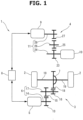
- FIG. 1 is an explanatory view schematically showing a driving system of a vehicle 1 to which the present invention is applied.
- FIG. 2 is an explanatory view schematically showing a system configuration of an internal combustion engine 10 according to the present invention.
- Vehicle 1 is, for example, a hybrid vehicle, and includes a driving unit 3 for driving drive wheels 2, and a power generation unit 4 for generating electric power for driving drive wheels 2.
- Driving unit 3 includes a drive motor 5 as an electric motor for rotatably driving drive wheels 2, and a first gear train 6 and a differential gear 7 for transmitting the driving force of drive motor 5 to drive wheels 2.
- the electric power from a battery 8 which is charged with electric power generated by power generation unit 4 is supplied to drive motor 5.
- Power generation unit 4 includes a generator 9 for generating the electric power to be supplied to drive motor 5, an internal combustion engine 10 for driving generator 9, and a second gear train 11 for transmitting the rotation of internal combustion engine 10 to generator 9.
- Vehicle 1 of the present embodiment is a so-called series hybrid vehicle in which internal combustion engine 10 is not used as motive power. That is, in vehicle 1 of the present embodiment, internal combustion engine 10 is only used for generating electric power, and drive motor 5 drives drive wheels 2 for traveling. For example, in vehicle 1, when the remaining amount (remaining charge amount) of battery 8 becomes low, generator 9 is driven by driving internal combustion engine 10 to generate electric power to charge battery 8. That is, vehicle 1 includes a traveling mode to travel only with the driving force of drive motor 5.
- Drive motor 5 is a direct drive source of vehicle 1, and is driven by, for example, AC power from battery 8.
- drive motor 5 is composed of a synchronous motor in which a permanent magnet is used to a rotor.
- drive motor 5 functions as a generator at the time of the deceleration of vehicle 1. That is, drive motor 5 is a generator motor which is capable of charging battery 8 with regenerative energy, as electric power, generated at the time of the vehicle deceleration.
- First gear train 6 reduces the rotation of drive motor 5 and increases motor toque so as to ensure traveling drive torque.
- First gear train 6 is, for example, a double reduction gear train, and includes a motor shaft 14 equipped with a drive unit first gear 13, and a first idler shaft 17 equipped with a drive unit second gear 15 and a drive unit third gear 16.
- Motor shaft 14 is the rotation shaft of drive motor 5.
- Drive unit first gear 13 meshes with drive unit second gear 15.
- Drive unit third gear 16 meshes with an input-side gear 18 provided on the input side of differential gear 7.
- Differential gear 7 transmits the driving torque input from first gear train 6 via input-side gear 18 to right and left drive wheels 2 and 2 via right and left drive shafts 19 and 19.
- Differential gear 7 is capable of transmitting the same driving torque to right and left drive wheels 2 and 2, while allowing the rotation speed difference between right and left drive wheels 2 and 2.
- generator 9 is composed of a synchronous motor in which a permanent magnet is used to a rotor.
- Generator 9 converts the rotation energy generated by internal combustion engine 10 into electric energy to charge, for example, battery 8.
- generator 9 also has a function as an electric motor for driving internal combustion engine 10, and functions as a starter motor at the time of the start of internal combustion engine 10. That is, generator 9 is a generator motor, is capable of supplying the generated electric power to battery 8, and is capable of being rotatably driven by the electric power from battery 8.
- the electric power generated by generator 9 is not used for charging battery 8, but may be directly supplied to drive motor 5 according to a driving condition.
- the start of internal combustion engine 10 may be carried out by a special starter motor different from generator 9.
- Second gear train 11 is a gear train connecting internal combustion engine 10 and generator 9.
- Second gear train 11 includes an engine shaft 24 equipped with a power generation unit first gear 23, a second idler shaft 26 equipped with a power generation unit second gear 25, and a generator input shaft 28 equipped with a power generation unit third gear 27.
- second gear train 11 increases the rotation speed of internal engine 10, and transmits a required engine torque to generator 9.
- generator 9 functions as a starter
- second gear train 11 reduces the rotation speed of generator 9, and transmits a required motor torque to internal combustion engine 10.
- Engine shaft 24 synchronously rotates with the crankshaft (not shown) of internal combustion engine 10.
- Generator input shaft 28 synchronously rotates with the rotor (not shown) of generator 9.
- Power generation unit first gear 23 meshes with power generation unit second gear 25.
- Power generation unit third gear 27 meshes with power generation unit second gear 25. That is, power generation unit first gear 23 and power generation unit third gear 27 mesh with power generation unit second gear 25.
- Internal combustion engine 10 is capable of changing an air-fuel ratio.
- Internal combustion engine 10 is, for example, a gasoline engine disposed inside the engine room positioned on the front side of vehicle 1.
- an exhaust passage 31 of internal combustion engine 10 is provided with an upstream-side exhaust purification catalyst 32 and a downstream-side exhaust purification catalyst 33 as a NOx purification catalyst.
- Upstream-side exhaust purification catalyst 32 is composed of, for example, a three-way catalyst.
- the three-way catalyst is one for purifying exhaust gas discharged from internal combustion engine 10, and when an excess air ratio is approximately "1", namely, when an exhaust gas air-fuel ratio is approximately the theoretical air-fuel ratio, the purification ratio of each of three components of HC, CO, and NOx in exhaust gas which flows thereinto becomes high.
- Downstream-side exhaust purification catalyst 33 is positioned more on the downstream side than upstream-side exhaust purification catalyst 32.
- Downstream-side exhaust purification catalyst 33 is composed of a NOx trap catalyst (LNT; Lean NOx Trap Catalyst).
- the NOx trap catalyst is one absorbing NOx in exhaust gas during the operation when the air-fuel ratio is an air-fuel ratio leaner than the theoretical air-fuel ratio, and desorbing and reducing (purifying) NOx during the operation when the air-fuel ratio is an air-fuel ratio richer than the theoretical air-fuel ratio.
- the NOx trap catalyst absorbs NOx in exhaust gas when the exhaust gas air-fuel ratio is lean, and performs the adsorption-reduction purification of the absorbed NOx by using HC (hydrocarbon) and CO, as reducing agents, in exhaust gas when the exhaust air-fuel ratio is rich.
- An upstream-side NOx sensor 42a is disposed between upstream-side exhaust purification catalyst 32 and downstream-side exhaust purification catalyst 33.
- a downstream-side NOx sensor 42b is provided on the downstream side of downstream-side exhaust purification catalyst 33. That is, a NOx sensor 42 is provided to the front and rear of downstream-side exhaust purification catalyst 33.
- Upstream-side NOx sensor 42a and downstream-side NOx sensor 42b are ones for detecting the concentration of NOx in exhaust gas.
- the detection signals of upstream-side NOx sensor 42a and downstream-side NOx sensor 42b are input to a control unit 41.
- Control unit 41 is a well-known digital computer equipped with a CPU, a ROM, a RAM and an input/output interface.
- Control unit 41 is input with detection signals of sensors such as an air flow meter 43 for detecting an intake air amount, a crank angle sensor 44 for detecting the crank angle of a crankshaft, an accelerator opening sensor 45 for detecting the depression amount of the accelerator pedal, a vehicle speed sensor 46 for detecting vehicle speed, a water temperature sensor 47 for detecting the temperature of the cooling water of internal combustion engine 10, and an oil temperature sensor 48 for detecting the temperature of the lubricant of internal combustion engine 10.
- Crank angle sensor 44 is one capable of detecting the engine speed of internal combustion engine 10.
- Control unit 41 calculates, by using the detection value of accelerator opening sensor 45, power consumption that is the amount of power required for vehicle traveling.
- the power consumption of the vehicle is the sum of the power consumed by drive motor 5 and the power consumed by other auxiliary machinery, by selecting a power set value close to this sum from a plurality of power set values previously discretely set, the power consumption of the vehicle may be obtained.
- control unit 41 is capable of detecting a SOC (State Of Charge) that is a ratio of a remaining charge amount with respect to the charge capacity of battery 8.
- SOC State Of Charge
- Control unit 41 calculates the NOx adsorption ratio of downstream-side exhaust purification catalyst 33 from the adsorption amount of NOx absorbed in downstream-side exhaust purification catalyst 33.
- the NOx adsorption ratio of downstream-side exhaust purification catalyst 33 is the ratio of a NOx adsorption amount to the maximum value (adsorption limit value) of a NOx amount that can be absorbed by downstream-side exhaust purification catalyst 33.
- Control unit 41 calculates the adsorption amount of NOx absorbed in downstream-side exhaust purification catalyst 33 by using the difference between the detection value of upstream-side NOx sensor 42a and the detection value of downstream-side NOx sensor 42b.
- control unit 41 may be configured to, in order to calculate the adsorption amount of NOx of downstream-side exhaust purification catalyst 33, obtain a NOx adsorption amount per unit of time from a predetermined date and the like previously stored in a ROM of control unit 41, such as the engine speed and the fuel injection amount of internal combustion 10 as parameters, and then integrate it.
- the NOx adsorption amount of downstream-side exhaust purification catalyst 33 may be calculated by wall-known methods other than the above method.
- Control unit 41 controls the air-fuel ratio of internal combustion engine 10 while optimally controlling the ignition timing, the intake air amount and the like of internal combustion engine 10, based on the detection signals of sensors. That is, control unit 41 corresponds to a control unit for controlling the operation of internal combustion engine 10.
- control unit 41 When operating internal combustion engine 10, control unit 41 basically controls the air-fuel ratio so as to be a lean air-fuel ratio (air-fuel ratio leaner than the theoretical air-fuel ratio), and controls, in case where combustion stability cannot be ensured at a lean air-fuel ratio, the air-fuel ratio so as to be the theoretical air-fuel ratio or an air-fuel ratio richer than the theoretical air-fuel ratio. In addition, in case where the after-mentioned rich spike is carried out, control unit 41 controls the air-fuel ratio so as to be an air-fuel ratio richer than the theoretical air-fuel ratio.
- control unit 41 stops internal combustion engine 10 (automatic stop) when a predetermined stop request is made during the operation of internal combustion engine 10, and restarts internal combustion engine 10 (automatic restart) when a predetermined start request is made during the stopping of internal combustion engine 10 and the traveling of vehicle 1.
- Control unit 41 determines that a stop request is made when the power consumption of the vehicle becomes equal to or lower than a power threshold set according to the vehicle speed, the SOC of battery 8 and the NOx adsorption ratio of downstream-side exhaust purification catalyst 33 or when the NOx adsorption ratio of downstream-side exhaust purification catalyst 33 becomes equal to or higher than a predetermined first NOx adsorption ratio threshold A1 which has been previously set, during the operation of internal combustion engine 10.
- the power threshold is calculated by using a plurality of power threshold calculation maps (mentioned below) prepared for respective NOx adsorption ratios.
- the power threshold is set so as to be larger as the NOx adsorption ratio of downstream-side exhaust purification catalyst 33 becomes higher. Consequently, internal combustion engine 10 easily stops as the NOx adsorption ratio of downstream-side exhaust purification catalyst 33 becomes higher.
- First NOx adsorption ratio threshold A1 is a value close to the limit of the NOx adsorption ratio (NOx adsorption ratio: 100%) of downstream-side exhaust purification catalyst 33, and, in the present embodiment, it is set to, for example, 95% in the NOx adsorption ratio.
- control unit 41 determines that a start request is made when the power consumption of the vehicle becomes larger than a power threshold or when the SOC of battery 8 becomes equal to or lower than a predetermined SOC lower limit value, during the stopping of internal combustion engine 10 in the operation state of vehicle 1.
- downstream-side exhaust purification catalyst 33 when the operation of internal combustion engine 10 is carried out at a lean air-fuel ratio, the NOx adsorption ratio increases, and it is therefore necessary to carry out NOx purge for desorbing and reducing the absorbed NOx.
- control unit 41 (internal combustion engine 10) carries out rich spike for shifting the air-fuel ratio to an air-fuel ratio richer than the theoretical air-fuel ratio by temporarily increasing the fuel injection amount of internal combustion engine 10.
- FIG. 3 is a timing chart showing one example of the operation of internal combustion engine 10 in a comparative embodiment.
- the comparative embodiment shown in FIG. 3 at the timing when the NOx adsorption ratio of downstream-side exhaust purification catalyst 33 reaches the adsorption limit (100%), the desorption and reduction of NOx absorbed in downstream-side exhaust purification catalyst 33 is carried out.
- a stop request of internal combustion engine 10 is made, and internal combustion engine 10 in an operation state at a lean air-fuel ratio is stopped.
- Control unit 41 (internal combustion engine 10) therefore starts the rich spike from the timing of time t5 in FIG. 3 .
- This rich spike is carried out such that all of NOx absorbed in downstream-side exhaust purification catalyst 33 is desorbed and reduced. That is, the rich spike is carried out until the NOx adsorption ratio of downstream-side exhaust purification catalyst 33 becomes 0%.
- the air-fuel ratio needs to be shifted twice in the order of "lean air-fuel ratio ⁇ rich air-fuel ratio ⁇ lean air-fuel ratio" during the operation of internal combustion engine 10.
- the shifting of the air-fuel ratio from a lean air-fuel ratio to a rich air-fuel ratio and the shifting of the air-fuel ratio from a rich air-fuel ratio to a lean air-fuel ratio become a factor causing the deterioration of the fuel economy performance and the exhaust performance of internal combustion engine 10.
- the present embodiment by carrying out the NOx purge at the time of the start of internal combustion engine 10, the number of times of the shifting of the air-fuel ratio in internal combustion engine 10 in the operation state is reduced.
- internal combustion engine 10 is stopped when the NOx adsorption ratio of downstream-side exhaust purification catalyst 33 becomes high, such that the NOx adsorption ratio of downstream-side exhaust purification catalyst 33 does not reach the adsorption limit (100%), during the operation at a lean air-fuel ratio.
- internal combustion engine 10 is stopped before the NOx adsorption ratio of downstream-side catalyst 33 reaches the limit such that the NOx adsorption ratio of downstream-side exhaust purification catalyst 33 does not reach the adsorption limit (100%), during the operation of internal combustion engine 10 at a lean air-fuel ratio, and the NOx purge is carried out at a timing when a start request of internal combustion engine 10 is made.
- control unit 41 determines that a stop request is made, and then stops internal combustion engine 10. In other words, control unit 41 determines whether to stop internal combustion engine 10 during operation by using the vehicle speed of vehicle 1, the SOC of battery 8 and the NOx adsorption ratio of downstream-side exhaust purification catalyst 33.
- control unit 41 determines that a stop request is also made when the NOx adsorption ratio of downstream-side exhaust purification catalyst 33 becomes first NOx adsorption ratio threshold A1 or higher during the operation of internal combustion engine 10, and then stops internal combustion engine 10.
- internal combustion engine 10 can be stopped before the NOx adsorption amount of downstream-side exhaust purification catalyst 33 reaches the limit. Therefore, in order to remove the NOx absorbed in downstream-side exhaust purification catalyst 33, internal combustion engine 10 can be operated without shifting the air-fuel to an air-fuel ratio richer than the theoretical air-fuel ratio during the operation at an air-fuel ratio leaner than the theoretical air-fuel ratio.
- control unit 41 prohibits a lean operation for setting the air-fuel ratio so as to be an air-fuel ratio leaner than the theoretical air-fuel ratio, when the NOx adsorption ratio of downstream-side exhaust purification catalyst 33 is equal to or higher than first NOx adsorption ratio threshold A1, at the time of the start of internal combustion engine 10.
- the NOx adsorption ratio of downstream-side exhaust purification catalyst 33 can be avoided from reaching the adsorption limit during the operation of internal combustion engine at a lean air-fuel ratio, and thereby the deterioration of the exhaust performance of internal combustion engine 10 can be suppressed.
- control unit 41 controls the air-fuel ratio so as to be richer than at least the theoretical air-fuel ratio to carry out the NOx purge of downstream-side exhaust purification catalyst 33.
- control unit 41 controls the air-fuel ratio so as to be richer than at least the theoretical air-fuel ratio to carry out the NOx purge of downstream-side exhaust purification catalyst 33.
- the NOx absorbed in downstream-side exhaust purification catalyst 33 can be removed at the time of the start, and it is no necessary to shift the air-fuel ratio to a rich air-fuel ratio to remove the NOx absorbed in downstream-side exhaust purification catalyst 33 during the operation at a lean air-fuel ratio. That is, in internal combustion engine 10, it becomes unnecessary to carry out the shifting of the air-fuel ratio including shifting to the operation at a rich air-fuel ratio, during the operation at a lean air-fuel ratio, to remove the NOx of downstream-side exhaust purification catalyst 33, and shifting to the operation at a lean air-fuel ratio after the removing of the NOx of downstream-side exhaust purification catalyst 33.
- control unit 41 starts internal combustion engine 10 at an air-fuel ratio richer than the theoretical air-fuel ratio, so as to remove NOx absorbed in downstream-side exhaust purification catalyst 33.
- cases where the air-fuel ratio needs to be set to the theoretical air-fuel ratio or an air-fuel ratio richer than the theoretical air-fuel ratio at the time of the start of internal combustion engine 10 namely, cases where the air-fuel ratio cannot be set to a lean air-fuel ratio at the time of the start of internal combustion engine 10 includes, for example, a case where the operation is carried out in an operation area in which the air-fuel ratio is not set to a lean air-fuel ratio immediately after the start of internal combustion engine 10, a case where the temperature of the cooling water of internal combustion engine 10 is low, and a case where the temperature of the lubricant of internal combustion engine 10 is low.
- second NOx adsorption ratio threshold A2 is a value smaller than first NOx adsorption ratio threshold A1, and, in the present embodiment, it is set to, for example, 30% in a NOx adsorption ratio.
- second NOx adsorption ratio threshold A2 can be set to 0% in a NOx adsorption ratio.
- FIG. 4 is a timing chart showing one example of the operation of internal combustion engine 10 according to the above-mentioned embodiment of the present invention.
- the present embodiment shown in FIG. 4 by carrying out NOx purge at the time of the start of internal combustion engine 10, the number of times of the shifting of the air-fuel ratio in internal combustion engine 10 in an operation state can be reduced.
- a stop request of internal combustion engine 10 is made at the timing of a time t1 in FIG. 4 , and internal combustion engine 10 in operation at a lean air-fuel ratio is stopped.
- a start request of internal combustion engine 10 is made at the timing of a time t4 in FIG. 4 , and internal combustion engine 10 is restated at the timing of time t4 in FIG. 4 .
- the NOx adsorption ratio of downstream-side catalyst 33 does not increase or decrease during a period from time t3 to time t4 in FIG. 4 when internal combustion engine 10 is stopped.
- control unit 41 (internal combustion engine 10) starts rich spike at the timing of time t4 in FIG. 4 .
- This rich spike is carried out so as to desorb and reduce all of the NOx absorbed in downstream-side exhaust purification catalyst 33. That is, the rich spike is carried out until the NOx adsorption ratio of downstream-side exhaust purification catalyst 33 becomes 0%.
- the rich spike is ended at the timing of a time t5 in FIG. 4 when the NOx adsorption amount of downstream-side exhaust purification catalyst 33 becomes "0", and the operation of internal combustion engine 10 at a lean air-fuel ratio is restarted.
- the NOx adsorption ratio of downstream-side exhaust purification catalyst 33 increases from the timing of a time t6 in FIG. 4 .
- the NOx purge of downstream-side exhaust purification catalyst 33 is carried out at the time of the start of internal combustion engine 10 in a stopping state.
- the shifting of the air-fuel ratio accompanying the NOx purge in the above-mentioned embodiment is therefore only the shifting of the air fuel ratio from a rich air-fuel ratio to a lean air-fuel ratio.
- the NOx purge can be carried out.
- FIG. 5 shows one example of a plurality of power threshold calculation maps prepared for respective NOx adsorption ratios (LNT adsorption ratios) of downstream-side exhaust purification catalyst 33.
- a plurality of power threshold calculation maps corresponding to NOx adsorption ratios (LNT adsorption ratios) other than those shown in FIG. 5 may be prepared.
- FIG. 5 there are shown a power threshold calculation map in which the NOx adsorption ratio (LNT adsorption ratio) is 0%, a power threshold calculation map in which the NOx adsorption ratio (LNT adsorption ratio) is 70%, a power threshold calculation map in which the NOx adsorption ratio (LNT adsorption ratio) is 80%, and a power threshold calculation map in which the NOx adsorption ratio (LNT adsorption ratio) is 90%.
- the display of specific numerical values in areas in which the SOC of battery 8 is low is omitted, and only specific numerical values in areas in which the SOC of battery 8 is high are displayed.
- power thresholds are also set in each area in which a specific numerical value is not displayed. For example, if the vehicle speed is the same, a power threshold is set such that the lower the SOC of battery 8 is, the smaller the value of the power threshold is.
- each of the power threshold calculation maps basically, if the vehicle speed of vehicle 1 and the SOC of battery 8 are under the same condition, the same power thresholds as other power threshold power calculation maps are set regardless of the NOx adsorption ratio of downstream-side exhaust purification catalyst 33. However, in each of the power threshold calculation maps in which the NOx adsorption is high, in a predetermined threshold variation area C in which the vehicle speed of vehicle 1 is low and the SOC of battery 8 is high, power thresholds different from those in the power threshold calculation maps in which the NOx adsorption ratio is low are set.
- the power threshold calculation maps in which the NOx adsorption ratio is high each have a predetermined power threshold variation area C in which values different from those in the power threshold calculation maps in which the NOx adsorption ratio is low are set.
- the values of the power thresholds set in threshold variation area C are larger than those of the power thresholds under the same conditions (vehicle speed of vehicle 1 and the SOC of battery 8) in the power threshold calculation maps in which the NOx adsorption ratio is low and threshold variation area C is not set.
- a value set in predetermined threshold variation area C in which the vehicle speed of vehicle 1 is low, the SOC of battery 8 is high, and the NOx adsorption ratio of downstream-side exhaust purification catalyst 33 is high is different from a value set in a predetermined normal area in which the vehicle speed of vehicle 1 is low, the SOC of battery 8 is high and the NOx adsorption ratio of downstream-side exhaust purification catalyst 33 is low.
- threshold variation area C is set in the power threshold calculation map in which the NOx adsorption ratio is 80% and the power threshold calculation map in which the NOx adsorption ratio is 90% in FIG. 5 .
- threshold variation area C is not set in the power threshold calculation map in which the NOx adsorption ratio is 70% and the power threshold calculation map in which the NOx adsorption ratio is 0% in FIG. 5 .
- the threshold variation area C is an area surrounded by a thick line in each of the power threshold calculation map in which the NOx adsorption ratio is 80% and the power threshold calculation map in which the NOx adsorption ratio is 90% in FIG. 5 . More specifically, threshold variation area C in the power threshold calculation map in which the NOx adsorption ratio is 80% is an area obtained by adding the area in which the vehicle speed is 10 km/h and the SOC of battery 8 is 80% and 85%, and the area in which the vehicle speed is 20 km/h and the SOC of battery 8 is 80% and 85%.
- threshold variation area C in the power threshold calculation map in which the NOx adsorption ratio is 90% is an area obtained by adding the area in which the vehicle speed is 10 km/h and the SOC of battery 8 is 75%, 80% and 85%, and the area in which the vehicle speed is 20 km/h and the SOC of battery 8 is 85%.
- the threshold variation area C is an area in which fuel economy is improved by carrying out the NOx purge at the time of the start after stopping internal combustion engine 10 earlier (in order to remove the NOx absorbed in downstream-side exhaust purification catalyst 33 by setting the air-fuel ratio so as to be richer than the theoretical air-fuel ratio).
- the value of each of the power thresholds is set higher in the area (threshold variation area C) in which fuel economy is improved by setting the air-fuel ratio so as to be richer than the theoretical air-fuel ratio at the time of the start after stopping internal combustion engine 10 earlier to remove the NOx absorbed in downstream-side exhaust purification catalyst 33.
- the power threshold calculation map in which the NOx adsorption ratio is 0% is the same as the power threshold calculation map in which the NOx adsorption ratio is 70%. That is, in the range from 0% to 70% in the NOx adsorption ratio of downstream-side exhaust purification catalyst 33, if the vehicle speed of vehicle 1 and the SOC of battery 8 are under the same conditions, in each of all the areas, the power threshold is the same value regardless of the NOx adsorption ratio of downstream-side exhaust purification catalyst 33.
- the power thresholds in threshold variation area C in which the vehicle speed of vehicle 1 is low and the SOC of battery 8 is high are set to values different from those in a normal area.
- the air-fuel ratio is set to an air-fuel ratio richer than the theoretical air-fuel ratio at the time of the start, so as to remove the NOx absorbed in downstream-side exhaust purification catalyst 33. That is, in case where the power consumption of the vehicle becomes equal to or lower than a power threshold in threshold variation area C, and internal combustion engine 10 is stopped, the air-fuel ratio is set to an air-fuel ratio richer than the theoretical air-fuel ratio at the time of the start of internal combustion engine 10 to remove the NOx absorbed in downstream-side exhaust purification catalyst 33.
- the values of the power thresholds of the power threshold calculation maps shown in FIG. 5 are appropriately set according to an actual machine, and are not limited to the values shown in FIG. 5 , as an example.
- threshold variation area C is not limited to the range shown in FIG. 5 , as an example, and it may be extended or reduced according to an actual machine. Moreover, there is possibility that threshold variation area C is set to a map in which, for example, the NOx adsorption ratio is 80% or lower depending on an actual machine.
- FIG. 6 is a flowchart showing one example of the flow of the control for internal combustion engine 10 in the embodiment mentioned above.
- the present routine is repeatedly executed by control unit 51 every predetermined time (for example, every 10 ms) during the traveling of vehicle 1.
- step S1 it is determined whether or not internal combustion engine 10 is in an operation state. When, in step S1, it is determined that internal combustion 10 is in the operation state, the process proceeds to a step S2. When it is determined that internal combustion engine 10 is not in the operation state, the process proceeds to a step S5.
- step S2 parameters such as the vehicle speed of vehicle 1, the SOC of battery 8 and the NOx adsorption ratio of downstream-side exhaust purification catalyst 33 are read.
- step S3 it is determined whether or not a stop request of internal combustion engine 10 is made.
- the process proceeds to a step S4, and internal combustion engine 10 in the operation state is stopped.
- step S3 it is determined that the stop request of internal combustion engine 10 is not made, the routine this time is ended.
- step S5 it is determined whether or not a start request of internal combustion engine 10 is made.
- step S5 it is determined that the start request of internal combustion engine 10 is made, the process proceeds to a step S6.
- step S5 it is determined that the start request of internal combustion engine 10 is not made, the routine this time is ended.
- step S6 it is determined whether or not the stop of internal combustion engine 10 this time is carried out on the bases that the power consumption of the vehicle becomes a power threshold or less in threshold variation area C.
- step S6 it is determined that internal combustion engine 10 is stopped on the bases that the power consumption of the vehicle becomes a power threshold or less in threshold variation area C
- the process proceeds to a step S7.
- step S8 it is not determined that internal combustion engine 10 is stopped on the bases that the power consumption of the vehicle becomes a power threshold or less in threshold variation area C.
- step S7 the NOx purge of downstream-side exhaust purification catalyst 33 is carried out at the time of the start of internal combustion engine 10. That is, internal combustion engine 10 is started at a rich air-fuel ratio richer than the theoretical air-fuel ratio, and this rich air-fuel ratio is maintained until all of the NOx absorbed in downstream-side exhaust purification catalyst 33 is desorbed and reduced.
- step S7 at the time of the start of internal combustion engine 10, the rich spike is carried out until the NOx adsorption ratio of downstream-side exhaust purification catalyst 33 becomes 0%.
- step S8 it is determined whether or not the NOx adsorption ratio of downstream-side exhaust purification catalyst 33 is equal to or higher than first NOx adsorption ratio threshold A1.
- step S8 it is determined that the NOx adsorption ratio of downstream-side exhaust purification catalyst 33 is equal to or higher than first NOx adsorption ratio threshold A1, the process proceeds to step S7.
- step S8 it is determined that the NOx adsorption ratio of downstream-side exhaust purification catalyst 33 is lower than first NOx adsorption ratio threshold A1, the process proceeds to a step S9.
- step S9 it is determined whether or not internal combustion engine 10 is in a cold state. Specifically, it is determined whether or not the temperature of the cooling water of internal combustion engine 10 is equal to or lower than a predetermined cooling water temperature threshold (temperature threshold) which is previously set, or it is determined whether or not the temperature of the lubricant of internal combustion engine 10 is equal to or lower than a predetermined lubricant temperature threshold (temperature threshold) which is previously set.
- a predetermined cooling water temperature threshold temperature threshold
- a predetermined lubricant temperature threshold temperature threshold
- step S9 When, in step S9, it is determined that internal combustion engine 10 is in a cold state, the process proceeds to a step S10. When, in step S9, it is determined that internal combustion engine 10 is not in a cold state, the process proceeds to a step S11.
- step S10 it is determined whether or not the NOx adsorption ratio of downstream-side exhaust purification catalyst 33 is equal to or higher than second NOx adsorption ratio threshold A2.
- step S10 it is determined that the NOx adsorption ratio of downstream-side exhaust purification catalyst 33 is equal to or higher than second NOx adsorption ratio threshold A2.
- step S7 it is determined that the NOx adsorption ratio of downstream-side exhaust purification catalyst 33 is lower than second NOx adsorption ratio threshold A2
- the process proceeds to a step S12.
- step S11 it is determined whether or not the operation is in an operation area in which the air-fuel ratio is not made lean. Specifically, for example, in case where an accelerator opening degree becomes full opening so as to operate the internal combustion engine with a high output immediately after starting, it is determined that the operation is in the operation area in which the air-fuel ratio is not made lean. When, in step S11, it is determined that the operation is in the operation area in which the air fuel ratio is not made lean, the process proceeds to step S10. When, in step S11, it is not determined that the operation is in the operation area in which the air-fuel ratio is not made lean, the process proceeds to a step S13.
- step S12 the operation of internal combustion engine 10 is started at the theoretical air-fuel ratio or an air-fuel ratio richer than the theoretical air-fuel ratio.
- step S12 in case where, for example, a start time increase amount of fuel is carried out, the air-fuel ratio in internal combustion engine 10 becomes an air-fuel ratio richer than the theoretical air-fuel ratio.
- step S13 the operation of internal combustion engine 10 is started at a lean air-fuel ratio.
- internal combustion engine 10 is a gasoline engine in the above-mentioned embodiment, it may be a diesel engine.
- internal combustion engine 10 is mounted on a series hybrid vehicle
- the present method and device can be not only applied to a series hybrid vehicle, but also could be applied, not according to the invention, to a hybrid vehicle including a traveling mode (for example, EV mode) to travel only with the driving force of a drive motor.
- a traveling mode for example, EV mode
- the power threshold is set such that the higher the NOx adsorption ratio of downstream-side exhaust purification catalyst 33 becomes, the larger the power threshold becomes, the traveling mode is easily shifted to the EV mode as the NOx adsorption ratio of downstream-side exhaust purification catalyst 33 becomes higher.
- the embodiment mentioned above relates to a method for controlling an internal combustion engine and a device for controlling the internal combustion engine.
Landscapes
- Engineering & Computer Science (AREA)
- Chemical & Material Sciences (AREA)
- Combustion & Propulsion (AREA)
- Mechanical Engineering (AREA)
- Transportation (AREA)
- General Engineering & Computer Science (AREA)
- Automation & Control Theory (AREA)
- Chemical Kinetics & Catalysis (AREA)
- Health & Medical Sciences (AREA)
- Toxicology (AREA)
- Power Engineering (AREA)
- Exhaust Gas After Treatment (AREA)
- Hybrid Electric Vehicles (AREA)
- Electrical Control Of Air Or Fuel Supplied To Internal-Combustion Engine (AREA)
- Control Of Vehicle Engines Or Engines For Specific Uses (AREA)
Claims (9)
- Procédé de commande d'un moteur à combustion interne (10), dans lequel :- le moteur à combustion interne (10) est monté sur un véhicule hybride à configuration en série (1),- le véhicule hybride à configuration en série (1) comprend un mode de déplacement pour se déplacer uniquement avec une force d'entraînement d'un moteur d'entraînement électrique (5),- le moteur à combustion interne (10) est capable de fonctionner à un rapport air-carburant plus pauvre qu'un rapport air-carburant théorique,- le procédé comprend la détermination consistant à savoir s'il faut arrêter le moteur à combustion interne (10), dans un état dans lequel le moteur à combustion interne (10) fonctionne, en tenant compte d'un rapport d'adsorption de NOx d'un catalyseur de purification de NOx (33) prévu dans un passage d'échappement (31) du moteur à combustion interne (10),- dans lequel le rapport d'adsorption de NOx est un rapport d'une quantité d'adsorption de NOx sur une valeur maximale d'une quantité de NOx qui peut être absorbée par le catalyseur de purification de NOx (33),- une condition de détermination pour autoriser l'arrêt du moteur à combustion interne (10) est assouplie lorsque le rapport d'adsorption de NOx est plus élevé,- dans lequel un seuil de puissance est défini en fonction d'une vitesse du véhicule, d'un SOC d'une batterie (8) et du rapport d'adsorption de NOx, le seuil de puissance étant un seuil de puissance électrique requise par le véhicule (1) pour se déplacer et pour des machines auxiliaires,- le seuil de puissance est défini de sorte que plus le rapport d'adsorption de NOx est élevé, plus le seuil de puissance est grand, et- lorsqu'une consommation de puissance électrique du véhicule hybride (1) est inférieure au seuil de puissance, l'arrêt du moteur à combustion interne (10) est autorisé.
- Procédé de commande du moteur à combustion interne (10) selon l'une quelconque des revendications précédentes, dans lequel lorsque le rapport d'adsorption de NOx devient supérieur ou égal à un premier seuil prédéterminé de rapport d'adsorption de NOx (A1), le moteur à combustion interne (10) est arrêté.
- Procédé de commande du moteur à combustion interne (10) selon l'une quelconque des revendications précédentes, dans lequel, au moment d'un démarrage du moteur à combustion interne (10), dans le cas où le rapport d'adsorption de NOx est supérieur ou égal à un premier seuil prédéterminé de rapport d'adsorption de NOx (A1), un fonctionnement en mélange pauvre dans lequel le rapport air-carburant est réglé à un rapport air-carburant plus pauvre que le rapport air-carburant théorique est interdit.
- Procédé de commande du moteur à combustion interne (10) selon la revendication 2 ou 3, dans lequel, au moment d'un démarrage du moteur à combustion interne (10), dans le cas où le rapport d'adsorption de NOx est supérieur ou égal au premier seuil prédéterminé de rapport d'adsorption de NOx (A1), le rapport air-carburant est réglé à un rapport air-carburant plus riche qu'au moins le rapport air-carburant théorique pour éliminer les NOx absorbés dans le catalyseur de purification de NOx (33), au moment du démarrage du moteur à combustion interne (10).
- Procédé de commande du moteur à combustion interne (10) selon la revendication 3 ou 4, dans lequel dans le cas où, au moment du démarrage, le rapport air-carburant doit être réglé au rapport air-carburant théorique ou à un rapport air-carburant plus riche que le rapport air-carburant théorique, lorsque le rapport d'adsorption de NOx est supérieur ou égal à un deuxième seuil prédéterminé de rapport d'adsorption de NOx (A2) inférieur au premier seuil de rapport d'adsorption de NOx (A1), le rapport air-carburant est réglé à un rapport air-carburant plus riche que le rapport air-carburant théorique, et le moteur à combustion interne (10) est démarré pour éliminer les NOx absorbés dans le catalyseur de purification de NOx (33).
- Procédé de commande du moteur à combustion interne (10) selon la revendication 1, dans lequel, une valeur du seuil de puissance définie dans une zone de variation de seuil prédéterminée (C) dans laquelle la vitesse du véhicule est faible, le SOC de la batterie (8) est élevé et le rapport d'adsorption de NOx est élevé est différente d'une valeur définie dans une zone normale prédéterminée dans laquelle la vitesse du véhicule est faible, le SOC de la batterie (8) est élevé et le rapport d'adsorption de NOx est faible.
- Procédé de commande du moteur à combustion interne (10) selon la revendication 6, dans lequel la zone de variation de seuil (C) est une zone dans laquelle le moteur à combustion interne (10) est arrêté plus tôt, et, au moment d'un démarrage du moteur à combustion interne (10), le rapport air-carburant est réglé à un rapport air-carburant plus riche que le rapport air-carburant théorique pour éliminer les NOx absorbés dans le catalyseur de purification de NOx (33) de manière à améliorer l'économie de carburant.
- Procédé de commande du moteur à combustion interne (10) selon la revendication 6 ou 7, dans lequel dans le cas où la consommation de puissance du véhicule hybride (1) devient inférieure ou égale au seuil de puissance dans la zone de variation de seuil (C), et le moteur à combustion interne (10) est arrêté, le rapport air-carburant est réglé à un rapport air-carburant plus riche que le rapport air-carburant théorique au moment d'un démarrage du moteur à combustion interne (10), pour éliminer les NOx absorbés dans le catalyseur de purification de NOx (33).
- Dispositif de commande d'un moteur à combustion interne (10), dans lequel :- le moteur à combustion interne (10) est monté sur un véhicule hybride à configuration en série (1),- le véhicule hybride à configuration en série (1) comprend un mode de déplacement pour se déplacer uniquement avec une force d'entraînement d'un moteur d'entraînement électrique (5),- le moteur à combustion interne (10) est capable de fonctionner à un rapport air-carburant plus pauvre qu'un rapport air-carburant théorique ;- une unité de commande (41) est comprise, qui est configurée pour commander le moteur à combustion interne (10),- l'unité de commande (41) est configurée pour déterminer s'il faut d'arrêter le moteur à combustion interne (10), dans un état dans lequel le moteur à combustion interne (10) fonctionne, en tenant compte d'un rapport d'adsorption de NOx d'un catalyseur de purification de NOx (33) prévu dans un passage d'échappement (31) du moteur à combustion interne (10),- le rapport d'adsorption de NOx est un rapport d'une quantité d'adsorption de NOx sur une valeur maximale d'une quantité de NOx qui peut être absorbée par le catalyseur de purification de NOx (33),- une condition de détermination pour autoriser l'arrêt du moteur à combustion interne (10) est assouplie lorsque le rapport d'adsorption de NOx est plus élevé,- dans lequel un seuil de puissance est défini en fonction d'une vitesse du véhicule, d'un SOC d'une batterie (8) et du rapport d'adsorption de NOx, le seuil de puissance étant un seuil de puissance électrique requise par le véhicule (1) pour se déplacer et pour des machines auxiliaires,- le seuil de puissance est défini de sorte que plus le rapport d'adsorption de NOx est élevé, plus le seuil de puissance est grand, et- lorsqu'une consommation de puissance électrique du véhicule hybride (1) est inférieure au seuil de puissance, l'arrêt du moteur à combustion interne (10) est autorisé.
Applications Claiming Priority (1)
| Application Number | Priority Date | Filing Date | Title |
|---|---|---|---|
| PCT/IB2019/001264 WO2021024011A1 (fr) | 2019-08-02 | 2019-08-02 | Procédé de commande de moteur à combustion interne et dispositif de commande de moteur à combustion interne |
Publications (3)
| Publication Number | Publication Date |
|---|---|
| EP4008888A1 EP4008888A1 (fr) | 2022-06-08 |
| EP4008888A4 EP4008888A4 (fr) | 2022-08-03 |
| EP4008888B1 true EP4008888B1 (fr) | 2024-08-07 |
Family
ID=74503780
Family Applications (1)
| Application Number | Title | Priority Date | Filing Date |
|---|---|---|---|
| EP19940204.1A Active EP4008888B1 (fr) | 2019-08-02 | 2019-08-02 | Procédé de commande de moteur à combustion interne et dispositif de commande de moteur à combustion interne |
Country Status (5)
| Country | Link |
|---|---|
| US (1) | US12104549B2 (fr) |
| EP (1) | EP4008888B1 (fr) |
| JP (1) | JP7190048B2 (fr) |
| CN (1) | CN114341476B (fr) |
| WO (1) | WO2021024011A1 (fr) |
Family Cites Families (24)
| Publication number | Priority date | Publication date | Assignee | Title |
|---|---|---|---|---|
| JP3506975B2 (ja) * | 1999-10-29 | 2004-03-15 | 本田技研工業株式会社 | ハイブリッド車両の制御装置 |
| JP2001241341A (ja) * | 2000-02-28 | 2001-09-07 | Hitachi Ltd | 内燃機関の排気ガス浄化装置及び浄化方法 |
| JP3982178B2 (ja) * | 2000-10-27 | 2007-09-26 | トヨタ自動車株式会社 | 有害ガス成分排出抑制型車輌 |
| JP4453235B2 (ja) * | 2001-09-11 | 2010-04-21 | トヨタ自動車株式会社 | 内燃機関の排気浄化装置 |
| JP2005248781A (ja) * | 2004-03-03 | 2005-09-15 | Toyota Motor Corp | 内燃機関の燃料カット制御装置 |
| JP2006132506A (ja) * | 2004-11-09 | 2006-05-25 | Toyota Motor Corp | 車両用内燃機関の燃料噴射制御装置 |
| JP2006307649A (ja) * | 2005-04-26 | 2006-11-09 | Toyota Motor Corp | エンジン停止またはアイドル要求を利用してNOx吸着触媒を再生するハイブリット車 |
| JP2007237794A (ja) * | 2006-03-06 | 2007-09-20 | Nissan Motor Co Ltd | ハイブリッド車両の排気浄化システム |
| US7487852B2 (en) * | 2006-03-06 | 2009-02-10 | Ford Global Technologies, Llc | System and method for controlling vehicle operation |
| JP4325700B2 (ja) * | 2007-05-09 | 2009-09-02 | トヨタ自動車株式会社 | 動力出力装置およびこれを搭載する車両並びに動力出力装置の制御方法 |
| JP2009035117A (ja) * | 2007-08-01 | 2009-02-19 | Nissan Motor Co Ltd | ハイブリッド車両における内燃機関の排気浄化制御装置 |
| WO2009060765A1 (fr) * | 2007-11-05 | 2009-05-14 | Mitsubishi Fuso Truck And Bus Corporation | Purificateur de gaz d'échappement de véhicule automobile hybride |
| JP2010007518A (ja) * | 2008-06-25 | 2010-01-14 | Nissan Motor Co Ltd | ディーゼルエンジンの排気浄化装置及び排気浄化方法 |
| WO2010134212A1 (fr) * | 2009-05-22 | 2010-11-25 | トヨタ自動車株式会社 | Appareil de purification d'échappement pour véhicule hybride |
| US9303576B2 (en) * | 2012-02-24 | 2016-04-05 | Ford Global Technologies, Llc | Method for controlling an engine |
| JP6003220B2 (ja) * | 2012-05-22 | 2016-10-05 | マツダ株式会社 | 内燃機関の排気ガス浄化方法及び装置 |
| US8862370B2 (en) * | 2012-08-02 | 2014-10-14 | Ford Global Technologies, Llc | NOx control during engine idle-stop operations |
| WO2014087501A1 (fr) * | 2012-12-05 | 2014-06-12 | トヨタ自動車株式会社 | Dispositif de commande de véhicule hybride |
| JP6207554B2 (ja) * | 2015-07-27 | 2017-10-04 | 本田技研工業株式会社 | 車両の排気浄化装置 |
| FR3062418B1 (fr) * | 2017-01-30 | 2019-06-07 | Renault S.A.S | Procede de controle des emissions d'oxydes d'azote a l'echappement d'un moteur a combustion interne |
| JP2018168725A (ja) * | 2017-03-29 | 2018-11-01 | トヨタ自動車株式会社 | ハイブリッド車の排気浄化システム |
| JP6863302B2 (ja) * | 2018-01-24 | 2021-04-21 | トヨタ自動車株式会社 | ハイブリッド車の排気浄化システム |
| US10920645B2 (en) * | 2018-08-02 | 2021-02-16 | Ford Global Technologies, Llc | Systems and methods for on-board monitoring of a passive NOx adsorption catalyst |
| CN113710555B (zh) * | 2019-04-19 | 2024-08-06 | 日产自动车株式会社 | 混合动力车辆的控制方法和混合动力车辆的控制装置 |
-
2019
- 2019-08-02 JP JP2021537521A patent/JP7190048B2/ja active Active
- 2019-08-02 EP EP19940204.1A patent/EP4008888B1/fr active Active
- 2019-08-02 CN CN201980098760.1A patent/CN114341476B/zh active Active
- 2019-08-02 US US17/631,981 patent/US12104549B2/en active Active
- 2019-08-02 WO PCT/IB2019/001264 patent/WO2021024011A1/fr not_active Ceased
Also Published As
| Publication number | Publication date |
|---|---|
| EP4008888A1 (fr) | 2022-06-08 |
| JP7190048B2 (ja) | 2022-12-14 |
| CN114341476A (zh) | 2022-04-12 |
| US20220282682A1 (en) | 2022-09-08 |
| WO2021024011A1 (fr) | 2021-02-11 |
| JPWO2021024011A1 (fr) | 2021-02-11 |
| EP4008888A4 (fr) | 2022-08-03 |
| CN114341476B (zh) | 2023-12-26 |
| US12104549B2 (en) | 2024-10-01 |
Similar Documents
| Publication | Publication Date | Title |
|---|---|---|
| JP4197038B2 (ja) | ハイブリッド自動車およびその制御方法 | |
| JP5060370B2 (ja) | 車両及び車両の制御方法 | |
| US20190023261A1 (en) | Hybrid vehicle | |
| JP4513751B2 (ja) | ハイブリッド車両およびその制御方法 | |
| JP2010179780A (ja) | ハイブリッド車およびその制御方法 | |
| JP2007126097A (ja) | ハイブリッド車及びその制御方法 | |
| JP2014073693A (ja) | ハイブリッド自動車 | |
| JP2019084939A (ja) | ハイブリッド自動車 | |
| JP2009269429A (ja) | ハイブリッド車両の制御装置 | |
| JP5904131B2 (ja) | ハイブリッド車両の制御装置およびハイブリッド車両 | |
| JP2007224848A (ja) | 内燃機関の制御装置 | |
| JP4730329B2 (ja) | 動力出力装置およびその制御方法並びに車両 | |
| JP2013154699A (ja) | 車両用制御装置 | |
| JP2014051199A (ja) | プラグインハイブリッド車両の制御装置 | |
| JP2010105626A (ja) | 車両およびその制御方法 | |
| JP2009299644A (ja) | 車両およびその制御方法 | |
| EP4008888B1 (fr) | Procédé de commande de moteur à combustion interne et dispositif de commande de moteur à combustion interne | |
| JP2013112101A (ja) | ハイブリッド車 | |
| JP5246090B2 (ja) | ハイブリッド車およびその制御方法 | |
| JP2002213592A (ja) | ハイブリッド車の機関回転速度制御装置 | |
| JP2003148202A (ja) | 内燃機関の空燃比制御装置 | |
| JP4548143B2 (ja) | ハイブリッド車両の排気浄化装置 | |
| JP2005110461A (ja) | パラレルハイブリッド車両におけるモータジェネレータの制御方法 | |
| JP4311414B2 (ja) | 車両およびその制御方法 | |
| US12612032B2 (en) | Control method of air fuel ratio for hybrid vehicle and control device of air fuel ratio for hybrid vehicle |
Legal Events
| Date | Code | Title | Description |
|---|---|---|---|
| STAA | Information on the status of an ep patent application or granted ep patent |
Free format text: STATUS: THE INTERNATIONAL PUBLICATION HAS BEEN MADE |
|
| PUAI | Public reference made under article 153(3) epc to a published international application that has entered the european phase |
Free format text: ORIGINAL CODE: 0009012 |
|
| STAA | Information on the status of an ep patent application or granted ep patent |
Free format text: STATUS: REQUEST FOR EXAMINATION WAS MADE |
|
| 17P | Request for examination filed |
Effective date: 20220214 |
|
| AK | Designated contracting states |
Kind code of ref document: A1 Designated state(s): AL AT BE BG CH CY CZ DE DK EE ES FI FR GB GR HR HU IE IS IT LI LT LU LV MC MK MT NL NO PL PT RO RS SE SI SK SM TR |
|
| A4 | Supplementary search report drawn up and despatched |
Effective date: 20220705 |
|
| RIC1 | Information provided on ipc code assigned before grant |
Ipc: F02D 41/02 20060101ALI20220629BHEP Ipc: B60L 50/16 20190101ALI20220629BHEP Ipc: B60W 10/06 20060101ALI20220629BHEP Ipc: B60W 20/16 20160101ALI20220629BHEP Ipc: F01N 3/20 20060101ALI20220629BHEP Ipc: F02D 29/02 20060101AFI20220629BHEP |
|
| DAV | Request for validation of the european patent (deleted) | ||
| DAX | Request for extension of the european patent (deleted) | ||
| GRAP | Despatch of communication of intention to grant a patent |
Free format text: ORIGINAL CODE: EPIDOSNIGR1 |
|
| STAA | Information on the status of an ep patent application or granted ep patent |
Free format text: STATUS: GRANT OF PATENT IS INTENDED |
|
| RAP1 | Party data changed (applicant data changed or rights of an application transferred) |
Owner name: NEW H POWERTRAIN HOLDING, S.L.U. Owner name: NISSAN MOTOR CO., LTD. |
|
| RIC1 | Information provided on ipc code assigned before grant |
Ipc: F02N 11/08 20060101ALI20240125BHEP Ipc: F02D 41/02 20060101ALI20240125BHEP Ipc: B60L 50/16 20190101ALI20240125BHEP Ipc: B60W 10/06 20060101ALI20240125BHEP Ipc: B60W 20/16 20160101ALI20240125BHEP Ipc: F01N 3/20 20060101ALI20240125BHEP Ipc: F02D 29/02 20060101AFI20240125BHEP |
|
| INTG | Intention to grant announced |
Effective date: 20240212 |
|
| GRAS | Grant fee paid |
Free format text: ORIGINAL CODE: EPIDOSNIGR3 |
|
| GRAJ | Information related to disapproval of communication of intention to grant by the applicant or resumption of examination proceedings by the epo deleted |
Free format text: ORIGINAL CODE: EPIDOSDIGR1 |
|
| GRAL | Information related to payment of fee for publishing/printing deleted |
Free format text: ORIGINAL CODE: EPIDOSDIGR3 |
|
| STAA | Information on the status of an ep patent application or granted ep patent |
Free format text: STATUS: REQUEST FOR EXAMINATION WAS MADE |
|
| GRAP | Despatch of communication of intention to grant a patent |
Free format text: ORIGINAL CODE: EPIDOSNIGR1 |
|
| STAA | Information on the status of an ep patent application or granted ep patent |
Free format text: STATUS: GRANT OF PATENT IS INTENDED |
|
| GRAA | (expected) grant |
Free format text: ORIGINAL CODE: 0009210 |
|
| STAA | Information on the status of an ep patent application or granted ep patent |
Free format text: STATUS: THE PATENT HAS BEEN GRANTED |
|
| INTC | Intention to grant announced (deleted) | ||
| INTG | Intention to grant announced |
Effective date: 20240701 |
|
| AK | Designated contracting states |
Kind code of ref document: B1 Designated state(s): AL AT BE BG CH CY CZ DE DK EE ES FI FR GB GR HR HU IE IS IT LI LT LU LV MC MK MT NL NO PL PT RO RS SE SI SK SM TR |
|
| REG | Reference to a national code |
Ref country code: GB Ref legal event code: FG4D |
|
| REG | Reference to a national code |
Ref country code: CH Ref legal event code: EP |
|
| REG | Reference to a national code |
Ref country code: IE Ref legal event code: FG4D |
|
| REG | Reference to a national code |
Ref country code: DE Ref legal event code: R096 Ref document number: 602019056835 Country of ref document: DE |
|
| REG | Reference to a national code |
Ref country code: LT Ref legal event code: MG9D |
|
| REG | Reference to a national code |
Ref country code: NL Ref legal event code: MP Effective date: 20240807 |
|
| PG25 | Lapsed in a contracting state [announced via postgrant information from national office to epo] |
Ref country code: NO Free format text: LAPSE BECAUSE OF FAILURE TO SUBMIT A TRANSLATION OF THE DESCRIPTION OR TO PAY THE FEE WITHIN THE PRESCRIBED TIME-LIMIT Effective date: 20241107 |
|
| REG | Reference to a national code |
Ref country code: AT Ref legal event code: MK05 Ref document number: 1711175 Country of ref document: AT Kind code of ref document: T Effective date: 20240807 |
|
| PG25 | Lapsed in a contracting state [announced via postgrant information from national office to epo] |
Ref country code: GR Free format text: LAPSE BECAUSE OF FAILURE TO SUBMIT A TRANSLATION OF THE DESCRIPTION OR TO PAY THE FEE WITHIN THE PRESCRIBED TIME-LIMIT Effective date: 20241108 Ref country code: NL Free format text: LAPSE BECAUSE OF FAILURE TO SUBMIT A TRANSLATION OF THE DESCRIPTION OR TO PAY THE FEE WITHIN THE PRESCRIBED TIME-LIMIT Effective date: 20240807 Ref country code: PT Free format text: LAPSE BECAUSE OF FAILURE TO SUBMIT A TRANSLATION OF THE DESCRIPTION OR TO PAY THE FEE WITHIN THE PRESCRIBED TIME-LIMIT Effective date: 20241209 Ref country code: FI Free format text: LAPSE BECAUSE OF FAILURE TO SUBMIT A TRANSLATION OF THE DESCRIPTION OR TO PAY THE FEE WITHIN THE PRESCRIBED TIME-LIMIT Effective date: 20240807 Ref country code: PL Free format text: LAPSE BECAUSE OF FAILURE TO SUBMIT A TRANSLATION OF THE DESCRIPTION OR TO PAY THE FEE WITHIN THE PRESCRIBED TIME-LIMIT Effective date: 20240807 |
|
| PG25 | Lapsed in a contracting state [announced via postgrant information from national office to epo] |
Ref country code: BG Free format text: LAPSE BECAUSE OF FAILURE TO SUBMIT A TRANSLATION OF THE DESCRIPTION OR TO PAY THE FEE WITHIN THE PRESCRIBED TIME-LIMIT Effective date: 20240807 |
|
| PG25 | Lapsed in a contracting state [announced via postgrant information from national office to epo] |
Ref country code: LV Free format text: LAPSE BECAUSE OF FAILURE TO SUBMIT A TRANSLATION OF THE DESCRIPTION OR TO PAY THE FEE WITHIN THE PRESCRIBED TIME-LIMIT Effective date: 20240807 |
|
| PG25 | Lapsed in a contracting state [announced via postgrant information from national office to epo] |
Ref country code: IS Free format text: LAPSE BECAUSE OF FAILURE TO SUBMIT A TRANSLATION OF THE DESCRIPTION OR TO PAY THE FEE WITHIN THE PRESCRIBED TIME-LIMIT Effective date: 20241207 Ref country code: AT Free format text: LAPSE BECAUSE OF FAILURE TO SUBMIT A TRANSLATION OF THE DESCRIPTION OR TO PAY THE FEE WITHIN THE PRESCRIBED TIME-LIMIT Effective date: 20240807 |
|
| PG25 | Lapsed in a contracting state [announced via postgrant information from national office to epo] |
Ref country code: HR Free format text: LAPSE BECAUSE OF FAILURE TO SUBMIT A TRANSLATION OF THE DESCRIPTION OR TO PAY THE FEE WITHIN THE PRESCRIBED TIME-LIMIT Effective date: 20240807 |
|
| PG25 | Lapsed in a contracting state [announced via postgrant information from national office to epo] |
Ref country code: RS Free format text: LAPSE BECAUSE OF FAILURE TO SUBMIT A TRANSLATION OF THE DESCRIPTION OR TO PAY THE FEE WITHIN THE PRESCRIBED TIME-LIMIT Effective date: 20241107 Ref country code: ES Free format text: LAPSE BECAUSE OF FAILURE TO SUBMIT A TRANSLATION OF THE DESCRIPTION OR TO PAY THE FEE WITHIN THE PRESCRIBED TIME-LIMIT Effective date: 20240807 |
|
| PG25 | Lapsed in a contracting state [announced via postgrant information from national office to epo] |
Ref country code: RS Free format text: LAPSE BECAUSE OF FAILURE TO SUBMIT A TRANSLATION OF THE DESCRIPTION OR TO PAY THE FEE WITHIN THE PRESCRIBED TIME-LIMIT Effective date: 20241107 Ref country code: PT Free format text: LAPSE BECAUSE OF FAILURE TO SUBMIT A TRANSLATION OF THE DESCRIPTION OR TO PAY THE FEE WITHIN THE PRESCRIBED TIME-LIMIT Effective date: 20241209 Ref country code: PL Free format text: LAPSE BECAUSE OF FAILURE TO SUBMIT A TRANSLATION OF THE DESCRIPTION OR TO PAY THE FEE WITHIN THE PRESCRIBED TIME-LIMIT Effective date: 20240807 Ref country code: NO Free format text: LAPSE BECAUSE OF FAILURE TO SUBMIT A TRANSLATION OF THE DESCRIPTION OR TO PAY THE FEE WITHIN THE PRESCRIBED TIME-LIMIT Effective date: 20241107 Ref country code: NL Free format text: LAPSE BECAUSE OF FAILURE TO SUBMIT A TRANSLATION OF THE DESCRIPTION OR TO PAY THE FEE WITHIN THE PRESCRIBED TIME-LIMIT Effective date: 20240807 Ref country code: LV Free format text: LAPSE BECAUSE OF FAILURE TO SUBMIT A TRANSLATION OF THE DESCRIPTION OR TO PAY THE FEE WITHIN THE PRESCRIBED TIME-LIMIT Effective date: 20240807 Ref country code: IS Free format text: LAPSE BECAUSE OF FAILURE TO SUBMIT A TRANSLATION OF THE DESCRIPTION OR TO PAY THE FEE WITHIN THE PRESCRIBED TIME-LIMIT Effective date: 20241207 Ref country code: HR Free format text: LAPSE BECAUSE OF FAILURE TO SUBMIT A TRANSLATION OF THE DESCRIPTION OR TO PAY THE FEE WITHIN THE PRESCRIBED TIME-LIMIT Effective date: 20240807 Ref country code: GR Free format text: LAPSE BECAUSE OF FAILURE TO SUBMIT A TRANSLATION OF THE DESCRIPTION OR TO PAY THE FEE WITHIN THE PRESCRIBED TIME-LIMIT Effective date: 20241108 Ref country code: FI Free format text: LAPSE BECAUSE OF FAILURE TO SUBMIT A TRANSLATION OF THE DESCRIPTION OR TO PAY THE FEE WITHIN THE PRESCRIBED TIME-LIMIT Effective date: 20240807 Ref country code: ES Free format text: LAPSE BECAUSE OF FAILURE TO SUBMIT A TRANSLATION OF THE DESCRIPTION OR TO PAY THE FEE WITHIN THE PRESCRIBED TIME-LIMIT Effective date: 20240807 Ref country code: BG Free format text: LAPSE BECAUSE OF FAILURE TO SUBMIT A TRANSLATION OF THE DESCRIPTION OR TO PAY THE FEE WITHIN THE PRESCRIBED TIME-LIMIT Effective date: 20240807 Ref country code: AT Free format text: LAPSE BECAUSE OF FAILURE TO SUBMIT A TRANSLATION OF THE DESCRIPTION OR TO PAY THE FEE WITHIN THE PRESCRIBED TIME-LIMIT Effective date: 20240807 |
|
| PG25 | Lapsed in a contracting state [announced via postgrant information from national office to epo] |
Ref country code: SM Free format text: LAPSE BECAUSE OF FAILURE TO SUBMIT A TRANSLATION OF THE DESCRIPTION OR TO PAY THE FEE WITHIN THE PRESCRIBED TIME-LIMIT Effective date: 20240807 Ref country code: DK Free format text: LAPSE BECAUSE OF FAILURE TO SUBMIT A TRANSLATION OF THE DESCRIPTION OR TO PAY THE FEE WITHIN THE PRESCRIBED TIME-LIMIT Effective date: 20240807 |
|
| PG25 | Lapsed in a contracting state [announced via postgrant information from national office to epo] |
Ref country code: EE Free format text: LAPSE BECAUSE OF FAILURE TO SUBMIT A TRANSLATION OF THE DESCRIPTION OR TO PAY THE FEE WITHIN THE PRESCRIBED TIME-LIMIT Effective date: 20240807 |
|
| PG25 | Lapsed in a contracting state [announced via postgrant information from national office to epo] |
Ref country code: CZ Free format text: LAPSE BECAUSE OF FAILURE TO SUBMIT A TRANSLATION OF THE DESCRIPTION OR TO PAY THE FEE WITHIN THE PRESCRIBED TIME-LIMIT Effective date: 20240807 |
|
| PG25 | Lapsed in a contracting state [announced via postgrant information from national office to epo] |
Ref country code: SK Free format text: LAPSE BECAUSE OF FAILURE TO SUBMIT A TRANSLATION OF THE DESCRIPTION OR TO PAY THE FEE WITHIN THE PRESCRIBED TIME-LIMIT Effective date: 20240807 |
|
| REG | Reference to a national code |
Ref country code: DE Ref legal event code: R097 Ref document number: 602019056835 Country of ref document: DE |
|
| PLBE | No opposition filed within time limit |
Free format text: ORIGINAL CODE: 0009261 |
|
| STAA | Information on the status of an ep patent application or granted ep patent |
Free format text: STATUS: NO OPPOSITION FILED WITHIN TIME LIMIT |
|
| 26N | No opposition filed |
Effective date: 20250508 |
|
| PG25 | Lapsed in a contracting state [announced via postgrant information from national office to epo] |
Ref country code: SE Free format text: LAPSE BECAUSE OF FAILURE TO SUBMIT A TRANSLATION OF THE DESCRIPTION OR TO PAY THE FEE WITHIN THE PRESCRIBED TIME-LIMIT Effective date: 20240807 |
|
| PGFP | Annual fee paid to national office [announced via postgrant information from national office to epo] |
Ref country code: DE Payment date: 20250902 Year of fee payment: 7 |
|
| PGFP | Annual fee paid to national office [announced via postgrant information from national office to epo] |
Ref country code: GB Payment date: 20250904 Year of fee payment: 7 |
|
| PGFP | Annual fee paid to national office [announced via postgrant information from national office to epo] |
Ref country code: FR Payment date: 20250829 Year of fee payment: 7 |
|
| PG25 | Lapsed in a contracting state [announced via postgrant information from national office to epo] |
Ref country code: IT Free format text: LAPSE BECAUSE OF FAILURE TO SUBMIT A TRANSLATION OF THE DESCRIPTION OR TO PAY THE FEE WITHIN THE PRESCRIBED TIME-LIMIT Effective date: 20240807 |
|
| REG | Reference to a national code |
Ref country code: CH Ref legal event code: H13 Free format text: ST27 STATUS EVENT CODE: U-0-0-H10-H13 (AS PROVIDED BY THE NATIONAL OFFICE) Effective date: 20260324 |
|
| PG25 | Lapsed in a contracting state [announced via postgrant information from national office to epo] |
Ref country code: MC Free format text: LAPSE BECAUSE OF FAILURE TO SUBMIT A TRANSLATION OF THE DESCRIPTION OR TO PAY THE FEE WITHIN THE PRESCRIBED TIME-LIMIT Effective date: 20240807 |
|
| PG25 | Lapsed in a contracting state [announced via postgrant information from national office to epo] |
Ref country code: LU Free format text: LAPSE BECAUSE OF NON-PAYMENT OF DUE FEES Effective date: 20250802 Ref country code: RO Free format text: LAPSE BECAUSE OF FAILURE TO SUBMIT A TRANSLATION OF THE DESCRIPTION OR TO PAY THE FEE WITHIN THE PRESCRIBED TIME-LIMIT Effective date: 20240807 |
|
| PG25 | Lapsed in a contracting state [announced via postgrant information from national office to epo] |
Ref country code: CH Free format text: LAPSE BECAUSE OF NON-PAYMENT OF DUE FEES Effective date: 20250831 |