EP4008932B1 - Transmission - Google Patents
Transmission Download PDFInfo
- Publication number
- EP4008932B1 EP4008932B1 EP20212033.3A EP20212033A EP4008932B1 EP 4008932 B1 EP4008932 B1 EP 4008932B1 EP 20212033 A EP20212033 A EP 20212033A EP 4008932 B1 EP4008932 B1 EP 4008932B1
- Authority
- EP
- European Patent Office
- Prior art keywords
- predetermined position
- shifting fork
- transmission
- sleeve
- gear
- Prior art date
- Legal status (The legal status is an assumption and is not a legal conclusion. Google has not performed a legal analysis and makes no representation as to the accuracy of the status listed.)
- Active
Links
Images



Classifications
-
- F—MECHANICAL ENGINEERING; LIGHTING; HEATING; WEAPONS; BLASTING
- F16—ENGINEERING ELEMENTS AND UNITS; GENERAL MEASURES FOR PRODUCING AND MAINTAINING EFFECTIVE FUNCTIONING OF MACHINES OR INSTALLATIONS; THERMAL INSULATION IN GENERAL
- F16H—GEARING
- F16H63/00—Control outputs from the control unit to change-speed- or reversing-gearings for conveying rotary motion or to other devices than the final output mechanism
- F16H63/02—Final output mechanisms therefor; Actuating means for the final output mechanisms
- F16H63/30—Constructional features of the final output mechanisms
- F16H63/32—Gear shift yokes, e.g. shift forks
-
- F—MECHANICAL ENGINEERING; LIGHTING; HEATING; WEAPONS; BLASTING
- F16—ENGINEERING ELEMENTS AND UNITS; GENERAL MEASURES FOR PRODUCING AND MAINTAINING EFFECTIVE FUNCTIONING OF MACHINES OR INSTALLATIONS; THERMAL INSULATION IN GENERAL
- F16H—GEARING
- F16H63/00—Control outputs from the control unit to change-speed- or reversing-gearings for conveying rotary motion or to other devices than the final output mechanism
- F16H63/02—Final output mechanisms therefor; Actuating means for the final output mechanisms
- F16H63/30—Constructional features of the final output mechanisms
-
- B—PERFORMING OPERATIONS; TRANSPORTING
- B60—VEHICLES IN GENERAL
- B60Y—INDEXING SCHEME RELATING TO ASPECTS CROSS-CUTTING VEHICLE TECHNOLOGY
- B60Y2200/00—Type of vehicle
- B60Y2200/90—Vehicles comprising electric prime movers
- B60Y2200/91—Electric vehicles
-
- F—MECHANICAL ENGINEERING; LIGHTING; HEATING; WEAPONS; BLASTING
- F16—ENGINEERING ELEMENTS AND UNITS; GENERAL MEASURES FOR PRODUCING AND MAINTAINING EFFECTIVE FUNCTIONING OF MACHINES OR INSTALLATIONS; THERMAL INSULATION IN GENERAL
- F16H—GEARING
- F16H63/00—Control outputs from the control unit to change-speed- or reversing-gearings for conveying rotary motion or to other devices than the final output mechanism
- F16H63/02—Final output mechanisms therefor; Actuating means for the final output mechanisms
- F16H63/30—Constructional features of the final output mechanisms
- F16H2063/3093—Final output elements, i.e. the final elements to establish gear ratio, e.g. coupling sleeves or other means establishing coupling to shaft
-
- F—MECHANICAL ENGINEERING; LIGHTING; HEATING; WEAPONS; BLASTING
- F16—ENGINEERING ELEMENTS AND UNITS; GENERAL MEASURES FOR PRODUCING AND MAINTAINING EFFECTIVE FUNCTIONING OF MACHINES OR INSTALLATIONS; THERMAL INSULATION IN GENERAL
- F16H—GEARING
- F16H63/00—Control outputs from the control unit to change-speed- or reversing-gearings for conveying rotary motion or to other devices than the final output mechanism
- F16H63/02—Final output mechanisms therefor; Actuating means for the final output mechanisms
- F16H63/30—Constructional features of the final output mechanisms
- F16H63/32—Gear shift yokes, e.g. shift forks
- F16H2063/324—Gear shift yokes, e.g. shift forks characterised by slide shoes, or similar means to transfer shift force to sleeve
-
- F—MECHANICAL ENGINEERING; LIGHTING; HEATING; WEAPONS; BLASTING
- F16—ENGINEERING ELEMENTS AND UNITS; GENERAL MEASURES FOR PRODUCING AND MAINTAINING EFFECTIVE FUNCTIONING OF MACHINES OR INSTALLATIONS; THERMAL INSULATION IN GENERAL
- F16H—GEARING
- F16H2200/00—Transmissions for multiple ratios
- F16H2200/0021—Transmissions for multiple ratios specially adapted for electric vehicles
-
- F—MECHANICAL ENGINEERING; LIGHTING; HEATING; WEAPONS; BLASTING
- F16—ENGINEERING ELEMENTS AND UNITS; GENERAL MEASURES FOR PRODUCING AND MAINTAINING EFFECTIVE FUNCTIONING OF MACHINES OR INSTALLATIONS; THERMAL INSULATION IN GENERAL
- F16H—GEARING
- F16H2200/00—Transmissions for multiple ratios
- F16H2200/003—Transmissions for multiple ratios characterised by the number of forward speeds
- F16H2200/0034—Transmissions for multiple ratios characterised by the number of forward speeds the gear ratios comprising two forward speeds
-
- F—MECHANICAL ENGINEERING; LIGHTING; HEATING; WEAPONS; BLASTING
- F16—ENGINEERING ELEMENTS AND UNITS; GENERAL MEASURES FOR PRODUCING AND MAINTAINING EFFECTIVE FUNCTIONING OF MACHINES OR INSTALLATIONS; THERMAL INSULATION IN GENERAL
- F16H—GEARING
- F16H3/00—Toothed gearings for conveying rotary motion with variable gear ratio or for reversing rotary motion
- F16H3/02—Toothed gearings for conveying rotary motion with variable gear ratio or for reversing rotary motion without gears having orbital motion
- F16H3/08—Toothed gearings for conveying rotary motion with variable gear ratio or for reversing rotary motion without gears having orbital motion exclusively or essentially with continuously meshing gears, that can be disengaged from their shafts
-
- F—MECHANICAL ENGINEERING; LIGHTING; HEATING; WEAPONS; BLASTING
- F16—ENGINEERING ELEMENTS AND UNITS; GENERAL MEASURES FOR PRODUCING AND MAINTAINING EFFECTIVE FUNCTIONING OF MACHINES OR INSTALLATIONS; THERMAL INSULATION IN GENERAL
- F16H—GEARING
- F16H63/00—Control outputs from the control unit to change-speed- or reversing-gearings for conveying rotary motion or to other devices than the final output mechanism
- F16H63/02—Final output mechanisms therefor; Actuating means for the final output mechanisms
- F16H63/30—Constructional features of the final output mechanisms
- F16H63/34—Locking or disabling mechanisms
- F16H63/3416—Parking lock mechanisms or brakes in the transmission
-
- F—MECHANICAL ENGINEERING; LIGHTING; HEATING; WEAPONS; BLASTING
- F16—ENGINEERING ELEMENTS AND UNITS; GENERAL MEASURES FOR PRODUCING AND MAINTAINING EFFECTIVE FUNCTIONING OF MACHINES OR INSTALLATIONS; THERMAL INSULATION IN GENERAL
- F16H—GEARING
- F16H63/00—Control outputs from the control unit to change-speed- or reversing-gearings for conveying rotary motion or to other devices than the final output mechanism
- F16H63/02—Final output mechanisms therefor; Actuating means for the final output mechanisms
- F16H63/30—Constructional features of the final output mechanisms
- F16H63/34—Locking or disabling mechanisms
- F16H63/3416—Parking lock mechanisms or brakes in the transmission
- F16H63/3425—Parking lock mechanisms or brakes in the transmission characterised by pawls or wheels
Definitions
- the invention relates to a transmission which comprises a shifting fork, where the transmission has a first gear state and a second gear state being selectable by means of the shifting fork, and the shifting fork is displaceable in an axial direction between a first predetermined position and a second predetermined position, where the first gear state is provided when the shifting fork is placed in the first predetermined position and the second gear state is provided when the shifting fork is placed in the second predetermined position.
- One actuator system is usually used for shifting two different elements, trying to reduce the size and complexity of the actuator system.
- the shifting is performed from a neutral position where a sleeve is arranged centred relative to a hub. By movement of the sleeve from the centred neutral position to the left, one dog clutch is engaged and by movement of the sleeve from the centred neutral position to the right, another dog clutch is engaged. In this way, different gear states of the transmission can be achieved.
- Document US2020/0070653 describes a powertrain with a power take-off unit.
- a power take-off/range gearing is used for shifting between the modes “two wheel drive high (2H)", “four wheel drive high (4H)” and “four wheel drive low (4L)”.
- the power take-off has an actuator for shifting between the modes.
- the modes are arranged in a row and achieved by moving a fork from mode 2H to mode 4H and further to mode 4L.
- An objective of the invention is to provide a transmission enabling the size and complexity of the transmission to be reduced.
- the objective is achieved by a transmission according to claim 1.
- the invention is based on the insight that by such a transmission, the shifting of two different elements, for example engagement of dog clutches, can be performed by movement of the shifting fork in one direction only. This enables a more compact design and also reduced shifting times.
- a transmission with a non-centred neutral position is achieved.
- the first predetermined position and the second predetermined position are arranged after each other without any gear state selectable by the shifting fork therebetween. This will however not exclude that any intermediate “gear state” could take place temporarily during the transition between the first predetermined position and the second predetermined position, though such a "gear state” is not selectable and have no substantial impact on the torque provided by the transmission.
- the "first gear” and the “second gear” have different gear ratios providing different gears for the transmission.
- the transmission can comprise a first shaft, a rotating member arranged on the first shaft, where the rotating member is rotationally journaled relative to the first shaft, and a hub arranged on the first shaft, where the hub is rotationally locked to the first shaft, and a sleeve moveable by means of the shifting fork in the axial direction, where the sleeve and the hub are engageable and rotationally locked to each other when engaged, and the sleeve and the rotating member are engageable and rotationally locked to each other when engaged, and in the first predetermined position of the shifting fork, the sleeve and the rotating member are engaged and the sleeve and the hub are engaged.
- the rotating member can be a gear wheel for instance.
- the rotating member such as a gear wheel idling in the non-centred neutral position
- the rotating member can be used, and further in the further predetermined position of the shifting fork, the sleeve and the rotating member are engaged and the sleeve and the hub are disengaged.
- the sleeve can have splines arranged on an external surface of the sleeve for engagement with splines of the rotating member arranged on an internal surface of the rotating member. Further, for engagement of the sleeve and the hub, the sleeve can have splines arranged on an internal surface of the sleeve for engagement with splines of the hub arranged on an external surface of the hub.
- the design can be even less space consuming.
- the transmission comprises a further component which is activated by the shifting fork in the second predetermined position of the shifting fork.
- the second gear state can be achieved in a rational way where the further component can be arranged on the first shaft of the transmission or on a second shaft of the transmission.
- the further component can be a further rotating member arranged on a shaft, such as a gear wheel, where the further rotating member is rotationally journaled relative to the shaft, and the further rotating member is rotationally locked to the shaft when activated by the shifting fork.
- This shaft onto which the further rotating member is arranged can be the first shaft or a second shaft of the transmission.
- the further predetermined position of the shifting fork is a first end position where the shifting fork is not movable further away from the second predetermined position
- the second predetermined position of the shifting fork is a second end position where the shifting fork is not movable further away from the further predetermined position
- Figs. 1A and 1B are schematic illustrations of a vehicle transmission 1, which is not encompassed by the wording of the claims but is considered as useful for understanding the claimed invention.
- the transmission 1 comprises a shifting fork 2.
- the transmission has a first gear state and a second gear state which are selectable by means of the shifting fork 2.
- the shifting fork 2 is displaceable in an axial direction 3 between a first predetermined position 4 (illustrated in Fig. 1A ) providing the first gear state and a second predetermined position 5 (illustrated in Fig. 1B ) providing the second gear state.
- the first gear state is provided when the shifting fork 2 is placed in the first predetermined position 4 and the second gear state is provided when the shifting fork 2 is placed in the second predetermined position 5.
- the first predetermined position 4 and the second predetermined position 5 are arranged one after the other without any further predetermined position providing a further selectable gear state arranged between the first predetermined position and the second predetermined position.
- the first gear state provides a first gear of the transmission and the second gear state provides a second gear of the transmission, i.e. none of the first gear state and the second gear state being a neutral position of the transmission.
- the transmission 1 comprises a first shaft 6, a rotating member 7 arranged on the first shaft 6, where the rotating member 7 is rotationally journaled relative to the first shaft 6.
- the rotating member 7 is suitably a gear wheel.
- the gear wheel 7 is a so called idling gear wheel which is journaled relative to the first shaft 6 but can be rotationally locked to the first shaft 6 through other components for transmitting torque between the gear wheel 7 and the first shaft 6.
- the transmission 1 further comprises a hub 8 arranged on the first shaft 6, where the hub 8 is rotationally locked to the first shaft 6, and a sleeve 9 moveable by means of the shifting fork 2.
- the sleeve 9 and the hub 8 are engageable with each other and are rotationally locked to each other when engaged.
- the sleeve 9 and the rotating member 7 are engageable with each other and are rotationally locked to each other when engaged.
- the sleeve 9 can have splines 10 arranged on an external surface of the sleeve for engagement with splines 11 of the rotating member 7 arranged on an internal surface of the rotating member.
- the sleeve 9 can have splines 12 arranged on an internal surface of the sleeve for engagement with splines 13 of the hub 8 arranged on an external surface of the hub.
- the sleeve 9 is moveable in the axial direction 3 by means of the shifting fork 2 for engagement and disengagement relative to the rotating member 7 and the hub 8.
- the sleeve can have splines arranged on an internal surface for engagement with splines arranged on an external surface of the rotating member such as a dog ring of a gear wheel. See embodiment illustrated in Figs. 4A and 4B.
- the gear wheel 7 is rotationally locked to the first shaft 6.
- the gear wheel 7 can be engaged with another gear wheel of another shaft for transmitting torque between the shafts (not shown).
- the transmission 1 suitably comprises a further component 14.
- the further component 14 is schematically illustrated in Figs. 1A and 1B by a square box.
- Fig. 1B the vehicle transmission in Fig. 1A is shown for the second gear state where the shifting fork 2 is positioned in the second predetermined position 5.
- the further component 14 is activated by the shifting fork 2 in the second shifting fork position 5, as schematically illustrated by an arm 15 of the shifting fork 2 reaching the further component 14, in another embodiment the further component 14 can be activated by the sleeve 9 if the further component 14 is arranged on the first shaft 6.
- the further component 14 can be arranged on the first shaft 6 of the transmission 1 or arranged on a second shaft of the transmission.
- the further component 14 can be directly activated by the shifting fork 2 or via a sleeve 9 or similar arranged on the first shaft 6 or another shaft.
- the further component 14 can be a park lock mechanism locking a shaft of the transmission against rotation when activated by the shifting fork 2.
- This shaft can be the first shaft 6 of the transmission 1 or another shaft of the transmission.
- the further component can be a further rotating member arranged on a shaft, such as a gear wheel, where the further rotating member is rotationally journaled relative to the shaft, and the further rotating member is rotationally locked to the shaft when activated by the shifting fork, for example via a sleeve.
- This shaft can be the first shaft 6 of the transmission 1 or another shaft of the transmission.
- the sleeve 9 has just been disengaged from the gear wheel 7, and the sleeve 9 and the gear wheel 7 are disengaged.
- the shifting fork 2 may have to be moved further away from the gear wheel 7 in the axial direction 3 to reach the second predetermined position 5.
- the sleeve 9 and the hub 8 can be engaged or disengaged in the second predetermined position 5, whereas the sleeve 9 and the gear wheel 7 always are disengaged in this position.
- the second sleeve may have to be displaced a certain distance while being engaged with the further component before reaching the second predetermined position, and in such a case the sleeve has to be disengaged from the gear wheel immediately before the second sleeve starts to engage the further component and remain disengaged during the further movement of the shifting fork towards the second predetermined position.
- first predetermined position 4 of the shifting fork 2 is suitably a first end position where the shifting fork 2 is not movable further away from the second predetermined position 5
- second predetermined position 5 of the shifting fork 2 is suitably a second end position where the shifting fork 2 is not movable further away from the first predetermined position 4.
- Figs. 2A, 2B and 2C represent an embodiment of the claimed invention and show a variant of the vehicle transmission 1'.
- Figs. 1A, 2B and 2C represent a variant of the vehicle transmission 1'.
- mainly different features of the transmission 1' relative to the transmission 1 in Figs. 1A and 1B will be described.
- Fig. 2A the transmission 1' is shown with the shifting fork 2 positioned in a further predetermined position 16.
- the hub 8 and the sleeve 9 are disengaged, and the sleeve 9 and the rotating member 7 are engaged.
- the further predetermined position 16 may constitute a neutral of the transmission 1'.
- Fig. 2A is a view of the vehicle transmission 1' shown for the further gear state which is a non-centred neutral where the shifting fork 2 is positioned in the further predetermined position 16, i.e. to the right in Fig. 2A .
- the journaled gear wheel 7 is idling, i.e. the gear wheel 7 is not rotationally locked to the first shaft 6.
- the shifting fork 2 is displaceable from the further predetermined position 16 to the first predetermined position 4' and further in the same direction from the first predetermined position 4' to the second predetermined position 5'.
- Fig. 2B is a view of the vehicle transmission 1' in Fig. 2A , shown for the first gear state providing the first gear where the shifting fork 2 is positioned in the first predetermined position 4'. This position of the shifting fork 2 corresponds to the position illustrated for the transmission in Fig. 1A .
- Fig. 2C is a view of the vehicle transmission 1' in Fig. 2A , shown for the second gear state providing the second gear or the park lock state, where the shifting fork 2 is positioned in the second predetermined position 5'. This position of the shifting fork 2 corresponds to the position illustrated for the transmission in Fig. 1B .
- the further predetermined position 16 of the shifting fork 2 is a first end position where the shifting fork 2 is not movable further away from the second predetermined position 5'
- the second predetermined position 5' of the shifting fork 2 is a second end position where the shifting fork 2 is not movable further away from the further predetermined position 16.
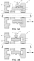
- a further variant of the transmission is illustrated.
- the further component is a further gear wheel 14' arranged on the first shaft 6.
- Fig. 3A is a view of the vehicle transmission 1" shown for the further gear state being a non-centred neutral, where the shifting fork 2 is positioned in the further predetermined position 16', i.e. to the right in Fig. 3A .
- the journaled gear wheel 7 is idling, i.e. the gear wheel 7 is not rotationally locked to the first shaft 6.
- the sleeve 9 and the gear wheel 7 are engaged, whereas the sleeve 9 and the hub 8 are disengaged.
- Fig. 3B is a view of the vehicle transmission 1" in Fig. 3A , shown for the first gear state providing the first gear where the shifting fork 2 is positioned in the first predetermined position 4".
- the hub 8 and the sleeve 9 are engaged, and the sleeve 9 and the gear wheel 7 are engaged, such that the gear wheel 7 is rotationally locked to the first shaft 6 for providing the first gear.
- the gear wheel 7 can be engaged with another gear wheel of another shaft for transmitting torque between the shafts (not shown).
- Fig. 3C is a view of the vehicle transmission 1" in Fig. 3A , shown for the second gear state providing a second gear where the shifting fork 2 is positioned in the second predetermined position 5".
- the sleeve 9 and the gear wheel 7 are disengaged, and the sleeve 9 and the further gear wheel 14' are engaged and the sleeve 9 and the hub 8 are engaged, such that the further gear wheel 14' is rotationally locked to the first shaft 6 for providing the second gear.
- the gear wheel 14' can be engaged with another gear wheel of another shaft for transmitting torque between the shafts (not shown).
Landscapes
- Engineering & Computer Science (AREA)
- General Engineering & Computer Science (AREA)
- Mechanical Engineering (AREA)
- Gear-Shifting Mechanisms (AREA)
Claims (11)
- Transmission (1' ; 1") comprenant une fourchette de changement de vitesse (2), la transmission ayant un premier état de vitesse et un second état de vitesse pouvant être sélectionnés au moyen de la fourchette de changement de vitesse (2), la fourchette de changement de vitesse étant déplaçable dans une direction axiale (3) entre une première position prédéterminée (4' ; 4") et une seconde position prédéterminée (5' ; 5"), le premier état de vitesse étant obtenu lorsque la fourchette de changement de vitesse (2) est placée dans la première position prédéterminée (4' ; 4") et le second état de vitesse étant obtenu lorsque la fourchette de changement de vitesse (2) est placée dans la seconde position prédéterminée (5' ; 5"), la première position prédéterminée (4' ; 4") et la seconde position prédéterminée (5' ; 5") étant disposées l'une après l'autre sans aucune autre position prédéterminée fournissant un autre état de vitesse sélectionnable disposé entre la première position prédéterminée et la seconde position prédéterminée, dans laquelle le premier état de vitesse fournit une première vitesse de la transmission (1' ; 1") et le second état de vitesse fournit une seconde vitesse de la transmission (1' ; 1"), la première vitesse et la seconde vitesse ayant des rapports de transmission différents fournissant des vitesses différentes pour la transmission, caractérisée en ce que la fourchette de changement de vitesse (2) peut être placée dans une autre position prédéterminée (16 ; 16') fournissant un autre état de vitesse étant un point mort de la transmission (1' ; 1"), la fourchette de changement de vitesse (2) étant déplaçable depuis la position prédéterminée supplémentaire (16 ; 16') à la première position prédéterminée (4' ; 4") et plus loin dans la même direction depuis la première position prédéterminée (4' ; 4") à la seconde position prédéterminée (5' ; 5").
- Transmission selon la revendication 1, caractérisée en ce que la transmission comprend un premier arbre (6), un élément rotatif (7) disposé sur le premier arbre, l'élément rotatif (7) étant tourillonné en rotation par rapport au premier arbre (6), et un moyeu (8) disposé sur le premier arbre (6), le moyeu (8) étant verrouillé en rotation sur le premier arbre (6), et un manchon (9) mobile au moyen de la fourchette de changement de vitesse (2) dans la direction axiale (3), le manchon (9) et le moyeu (8) pouvant être en prise et verrouillés en rotation l'un par rapport à l'autre lorsqu'ils sont en prise, et le manchon (9) et l'élément rotatif (7) pouvant être en prise et verrouillés en rotation l'un par rapport à l'autre lorsqu'ils sont en prise, dans laquelle la première position prédéterminée (4) de la fourchette de changement de vitesse (2), le manchon (9) et l'élément rotatif (7) sont en prise et le manchon (9) et le moyeu (8) sont en prise.
- Transmission selon la revendication 2, caractérisée en ce que l'élément rotatif est une roue dentée (7).
- Transmission selon les revendications 1 et 2, caractérisée en ce que dans la position prédéterminée supplémentaire (16) de la fourchette de changement de vitesse (2), le manchon (9) et l'élément rotatif (7) sont en prise et le manchon (9) et le moyeu (8) sont dégagés.
- Transmission selon une quelconque revendication précédente, caractérisée en ce que la transmission (1' ; 1") comprend un autre composant (14 ; 14') qui est activé par la fourchette de changement de vitesse (2) dans la seconde position prédéterminée (5' ; 5") de la fourchette de changement de vitesse (2).
- Transmission selon la revendication 5, caractérisée en ce que l'autre composant est un autre élément rotatif (14') disposé sur un arbre (6), l'autre élément rotatif (14') étant tourillonné en rotation par rapport à l'arbre (6), et l'autre élément rotatif (14') étant verrouillé en rotation sur l'arbre (6) lorsqu'il est activé par la fourchette de changement de vitesse (2).
- Transmission selon la revendication 6, caractérisée en ce que le second état de vitesse fournit la seconde vitesse et l'autre élément rotatif est une roue dentée (14').
- Transmission selon les revendications 2 et 5, caractérisée en ce que l'autre composant (14') est disposé sur le premier arbre (6) de la transmission (1").
- Transmission selon les revendications 2 et 5, caractérisée en ce que l'autre composant est disposé sur un second arbre de transmission (1' ; 1").
- Transmission selon l'une quelconque des revendications 2 et 3, caractérisée en ce que le manchon (9) comporte des cannelures (10) disposées sur une surface externe du manchon pour venir en prise avec des cannelures (11) de l'élément rotatif (7) disposées sur une surface interne de l'élément rotatif, et le manchon (9) comporte des cannelures (12) disposées sur une surface interne du manchon pour venir en prise avec des cannelures (13) du moyeu (8) disposées sur une surface externe du moyeu.
- Transmission selon la revendication 1, caractérisée en ce que l'autre position prédéterminée (16 ; 16') de la fourchette de changement de vitesse (2) est une première position finale dans laquelle la fourchette de changement de vitesse ne peut pas s'éloigner davantage de la seconde position prédéterminée (5' ; 5"), et la seconde position prédéterminée (5' ; 5") de la fourchette de changement de vitesse (2) est une seconde position finale dans laquelle la fourchette de changement de vitesse ne peut pas s'éloigner davantage de la position prédéterminée supplémentaire (16' ; 16").
Priority Applications (4)
| Application Number | Priority Date | Filing Date | Title |
|---|---|---|---|
| EP20212033.3A EP4008932B1 (fr) | 2020-12-04 | 2020-12-04 | Transmission |
| CN202180080612.4A CN116568949B (zh) | 2020-12-04 | 2021-11-25 | 变速器 |
| PCT/CN2021/133063 WO2022116889A1 (fr) | 2020-12-04 | 2021-11-25 | Boîte de vitesses |
| US18/138,056 US12163586B2 (en) | 2020-12-04 | 2023-04-22 | Transmission |
Applications Claiming Priority (1)
| Application Number | Priority Date | Filing Date | Title |
|---|---|---|---|
| EP20212033.3A EP4008932B1 (fr) | 2020-12-04 | 2020-12-04 | Transmission |
Publications (2)
| Publication Number | Publication Date |
|---|---|
| EP4008932A1 EP4008932A1 (fr) | 2022-06-08 |
| EP4008932B1 true EP4008932B1 (fr) | 2023-11-15 |
Family
ID=73726744
Family Applications (1)
| Application Number | Title | Priority Date | Filing Date |
|---|---|---|---|
| EP20212033.3A Active EP4008932B1 (fr) | 2020-12-04 | 2020-12-04 | Transmission |
Country Status (4)
| Country | Link |
|---|---|
| US (1) | US12163586B2 (fr) |
| EP (1) | EP4008932B1 (fr) |
| CN (1) | CN116568949B (fr) |
| WO (1) | WO2022116889A1 (fr) |
Families Citing this family (1)
| Publication number | Priority date | Publication date | Assignee | Title |
|---|---|---|---|---|
| CN118387059B (zh) * | 2024-03-29 | 2026-04-03 | 比亚迪股份有限公司 | 一种车辆的驻车装置、驻车控制方法、存储介质、系统和车辆 |
Family Cites Families (17)
| Publication number | Priority date | Publication date | Assignee | Title |
|---|---|---|---|---|
| US4431073A (en) * | 1981-12-03 | 1984-02-14 | Fairfield Manufacturing Co., Inc. | Two speed final drive gear box |
| FR2811051B1 (fr) | 2000-06-30 | 2002-10-04 | Renault | Dispositif de commande pour relier un pignon monte fou sur un arbre et cet arbre, notamment pour boite de vitesses de vehicule automobile |
| DE10224357A1 (de) | 2002-05-29 | 2003-12-11 | Daimler Chrysler Ag | Elastische Schalt- oder Schiebemuffe und Gangsprungsichere Formschlusskupplung |
| US6824491B2 (en) * | 2003-03-25 | 2004-11-30 | Power Network Industry Co., Ltd. | Power transmission device with automatic speed switching mechanism |
| CN101377229B (zh) * | 2007-08-29 | 2012-12-19 | 苏州宝时得电动工具有限公司 | 变速工具及其变速控制方法 |
| CN201093036Y (zh) * | 2007-08-31 | 2008-07-30 | 苏州宝时得电动工具有限公司 | 变速工具 |
| CN101463901B (zh) * | 2007-12-17 | 2012-11-21 | 比亚迪股份有限公司 | 驻车和换档执行机构 |
| CN101637901B (zh) * | 2008-07-31 | 2011-12-07 | 苏州宝时得电动工具有限公司 | 变速工具 |
| CN102562959A (zh) * | 2010-12-30 | 2012-07-11 | 苏州宝时得电动工具有限公司 | 变速工具 |
| CN103998828B (zh) * | 2012-12-12 | 2015-08-05 | 丰田自动车株式会社 | 车辆的动力传递装置 |
| DE102013108300A1 (de) * | 2013-08-01 | 2015-02-05 | Thyssenkrupp Presta Teccenter Ag | Schaltgetriebe für eine Antriebseinheit eines Elektrofahrzeugs und Verfahren zum Betrieb des Schaltgetriebes |
| DE102013108736A1 (de) | 2013-08-12 | 2015-02-12 | Hoerbiger Antriebstechnik Holding Gmbh | Klauenschaltung für ein Fahrzeuggetriebe |
| DE112014003878B4 (de) * | 2013-08-23 | 2023-08-03 | American Axle & Manufacturing, Inc. | Kraftübertragungsbauteil mit Doppelgabelaktuator |
| DE102014114006A1 (de) * | 2014-09-26 | 2016-03-31 | Getrag Ford Transmissions Gmbh | Schaltgetriebe für ein Kraftfahrzeug |
| JP6380272B2 (ja) * | 2015-07-23 | 2018-08-29 | トヨタ車体株式会社 | 電気自動車、2段変速機構及びインホイールモータ |
| DE102018118548A1 (de) * | 2018-07-31 | 2020-02-06 | Schaeffler Technologies AG & Co. KG | Zwei-Gang-Getriebe für ein elektrisch antreibbares Kraftfahrzeug |
| US10913350B2 (en) * | 2018-09-04 | 2021-02-09 | Ford Global Technologies, Llc | Ranged power take-off unit for transaxle |
-
2020
- 2020-12-04 EP EP20212033.3A patent/EP4008932B1/fr active Active
-
2021
- 2021-11-25 WO PCT/CN2021/133063 patent/WO2022116889A1/fr not_active Ceased
- 2021-11-25 CN CN202180080612.4A patent/CN116568949B/zh active Active
-
2023
- 2023-04-22 US US18/138,056 patent/US12163586B2/en active Active
Also Published As
| Publication number | Publication date |
|---|---|
| WO2022116889A1 (fr) | 2022-06-09 |
| CN116568949B (zh) | 2026-04-10 |
| CN116568949A (zh) | 2023-08-08 |
| US12163586B2 (en) | 2024-12-10 |
| US20230265921A1 (en) | 2023-08-24 |
| EP4008932A1 (fr) | 2022-06-08 |
Similar Documents
| Publication | Publication Date | Title |
|---|---|---|
| EP3120045B1 (fr) | Architecture de boîte de vitesses à usage intensif | |
| EP1845289A2 (fr) | Dispositif d'embrayage de transmission à embrayage double | |
| US20110167957A1 (en) | Automatic dual-clutch transmission | |
| EP2886911B1 (fr) | Ensemble actionneur de changement de vitesse sous charge de ressort ayant un mécanisme de retenue | |
| WO2015183153A1 (fr) | Boîte de vitesses pour un véhicule et véhicule comprenant une telle boîte de vitesses | |
| EP2423527B1 (fr) | Agencement de transmission | |
| WO2019141684A1 (fr) | Chaîne cinématique électrique et procédé de changement de vitesses | |
| US9719564B2 (en) | Synchronizer re-energization for improved cold shift comfort | |
| US5711186A (en) | Reverse synchronizer mechanism of manual transmission for a vehicle | |
| EP4008932B1 (fr) | Transmission | |
| JP2011098679A (ja) | 機械式自動変速機の制御装置 | |
| EP1357317B1 (fr) | Synchronisateur à actionnement électrique pour une transmission de véhicule | |
| US12305752B2 (en) | Transmission | |
| CN210600140U (zh) | 一种换挡机构、动力系统和电动车 | |
| US4800769A (en) | Transmission dual idler reverse drive mechanism | |
| EP2843260A1 (fr) | Transmission manuelle automatique | |
| EP1828632A2 (fr) | Transmission et synchroniseur | |
| CN111946756A (zh) | 用于车辆变速器的解耦系统、车辆变速器和车辆 | |
| US11701966B2 (en) | Driveline component including multi-function actuator | |
| EP3864321B1 (fr) | Boîte de vitesses de véhicule et véhicule comprenant une telle boîte de vitesses | |
| JP2002500327A (ja) | 自動車ギヤボックス | |
| KR100225960B1 (ko) | 수동변속기의 레버식 싱크로메시 기구 | |
| SE540153C2 (en) | Changing Gear Ratio in a Gearbox of a Vehicle | |
| WO2010123436A1 (fr) | Véhicule comprenant un dispositif de transmission avec un arbre de prise de force | |
| WO2011013043A1 (fr) | Boîte de vitesses pour véhicules à moteur |
Legal Events
| Date | Code | Title | Description |
|---|---|---|---|
| PUAI | Public reference made under article 153(3) epc to a published international application that has entered the european phase |
Free format text: ORIGINAL CODE: 0009012 |
|
| STAA | Information on the status of an ep patent application or granted ep patent |
Free format text: STATUS: REQUEST FOR EXAMINATION WAS MADE |
|
| 17P | Request for examination filed |
Effective date: 20201204 |
|
| AK | Designated contracting states |
Kind code of ref document: A1 Designated state(s): AL AT BE BG CH CY CZ DE DK EE ES FI FR GB GR HR HU IE IS IT LI LT LU LV MC MK MT NL NO PL PT RO RS SE SI SK SM TR |
|
| STAA | Information on the status of an ep patent application or granted ep patent |
Free format text: STATUS: EXAMINATION IS IN PROGRESS |
|
| 17Q | First examination report despatched |
Effective date: 20230201 |
|
| GRAP | Despatch of communication of intention to grant a patent |
Free format text: ORIGINAL CODE: EPIDOSNIGR1 |
|
| STAA | Information on the status of an ep patent application or granted ep patent |
Free format text: STATUS: GRANT OF PATENT IS INTENDED |
|
| INTG | Intention to grant announced |
Effective date: 20230609 |
|
| GRAS | Grant fee paid |
Free format text: ORIGINAL CODE: EPIDOSNIGR3 |
|
| GRAA | (expected) grant |
Free format text: ORIGINAL CODE: 0009210 |
|
| STAA | Information on the status of an ep patent application or granted ep patent |
Free format text: STATUS: THE PATENT HAS BEEN GRANTED |
|
| AK | Designated contracting states |
Kind code of ref document: B1 Designated state(s): AL AT BE BG CH CY CZ DE DK EE ES FI FR GB GR HR HU IE IS IT LI LT LU LV MC MK MT NL NO PL PT RO RS SE SI SK SM TR |
|
| REG | Reference to a national code |
Ref country code: CH Ref legal event code: EP Ref country code: GB Ref legal event code: FG4D |
|
| REG | Reference to a national code |
Ref country code: DE Ref legal event code: R096 Ref document number: 602020021021 Country of ref document: DE |
|
| REG | Reference to a national code |
Ref country code: IE Ref legal event code: FG4D |
|
| REG | Reference to a national code |
Ref country code: LT Ref legal event code: MG9D |
|
| REG | Reference to a national code |
Ref country code: NL Ref legal event code: MP Effective date: 20231115 |
|
| PG25 | Lapsed in a contracting state [announced via postgrant information from national office to epo] |
Ref country code: IS Free format text: LAPSE BECAUSE OF FAILURE TO SUBMIT A TRANSLATION OF THE DESCRIPTION OR TO PAY THE FEE WITHIN THE PRESCRIBED TIME-LIMIT Effective date: 20240315 |
|
| PG25 | Lapsed in a contracting state [announced via postgrant information from national office to epo] |
Ref country code: LT Free format text: LAPSE BECAUSE OF FAILURE TO SUBMIT A TRANSLATION OF THE DESCRIPTION OR TO PAY THE FEE WITHIN THE PRESCRIBED TIME-LIMIT Effective date: 20231115 |
|
| REG | Reference to a national code |
Ref country code: AT Ref legal event code: MK05 Ref document number: 1632053 Country of ref document: AT Kind code of ref document: T Effective date: 20231115 |
|
| PG25 | Lapsed in a contracting state [announced via postgrant information from national office to epo] |
Ref country code: NL Free format text: LAPSE BECAUSE OF FAILURE TO SUBMIT A TRANSLATION OF THE DESCRIPTION OR TO PAY THE FEE WITHIN THE PRESCRIBED TIME-LIMIT Effective date: 20231115 |
|
| PG25 | Lapsed in a contracting state [announced via postgrant information from national office to epo] |
Ref country code: AT Free format text: LAPSE BECAUSE OF FAILURE TO SUBMIT A TRANSLATION OF THE DESCRIPTION OR TO PAY THE FEE WITHIN THE PRESCRIBED TIME-LIMIT Effective date: 20231115 |
|
| PG25 | Lapsed in a contracting state [announced via postgrant information from national office to epo] |
Ref country code: ES Free format text: LAPSE BECAUSE OF FAILURE TO SUBMIT A TRANSLATION OF THE DESCRIPTION OR TO PAY THE FEE WITHIN THE PRESCRIBED TIME-LIMIT Effective date: 20231115 |
|
| PG25 | Lapsed in a contracting state [announced via postgrant information from national office to epo] |
Ref country code: NL Free format text: LAPSE BECAUSE OF FAILURE TO SUBMIT A TRANSLATION OF THE DESCRIPTION OR TO PAY THE FEE WITHIN THE PRESCRIBED TIME-LIMIT Effective date: 20231115 Ref country code: LT Free format text: LAPSE BECAUSE OF FAILURE TO SUBMIT A TRANSLATION OF THE DESCRIPTION OR TO PAY THE FEE WITHIN THE PRESCRIBED TIME-LIMIT Effective date: 20231115 Ref country code: IS Free format text: LAPSE BECAUSE OF FAILURE TO SUBMIT A TRANSLATION OF THE DESCRIPTION OR TO PAY THE FEE WITHIN THE PRESCRIBED TIME-LIMIT Effective date: 20240315 Ref country code: ES Free format text: LAPSE BECAUSE OF FAILURE TO SUBMIT A TRANSLATION OF THE DESCRIPTION OR TO PAY THE FEE WITHIN THE PRESCRIBED TIME-LIMIT Effective date: 20231115 Ref country code: BG Free format text: LAPSE BECAUSE OF FAILURE TO SUBMIT A TRANSLATION OF THE DESCRIPTION OR TO PAY THE FEE WITHIN THE PRESCRIBED TIME-LIMIT Effective date: 20240215 Ref country code: AT Free format text: LAPSE BECAUSE OF FAILURE TO SUBMIT A TRANSLATION OF THE DESCRIPTION OR TO PAY THE FEE WITHIN THE PRESCRIBED TIME-LIMIT Effective date: 20231115 Ref country code: PT Free format text: LAPSE BECAUSE OF FAILURE TO SUBMIT A TRANSLATION OF THE DESCRIPTION OR TO PAY THE FEE WITHIN THE PRESCRIBED TIME-LIMIT Effective date: 20240315 |
|
| PG25 | Lapsed in a contracting state [announced via postgrant information from national office to epo] |
Ref country code: SE Free format text: LAPSE BECAUSE OF FAILURE TO SUBMIT A TRANSLATION OF THE DESCRIPTION OR TO PAY THE FEE WITHIN THE PRESCRIBED TIME-LIMIT Effective date: 20231115 Ref country code: RS Free format text: LAPSE BECAUSE OF FAILURE TO SUBMIT A TRANSLATION OF THE DESCRIPTION OR TO PAY THE FEE WITHIN THE PRESCRIBED TIME-LIMIT Effective date: 20231115 Ref country code: PL Free format text: LAPSE BECAUSE OF FAILURE TO SUBMIT A TRANSLATION OF THE DESCRIPTION OR TO PAY THE FEE WITHIN THE PRESCRIBED TIME-LIMIT Effective date: 20231115 Ref country code: NO Free format text: LAPSE BECAUSE OF FAILURE TO SUBMIT A TRANSLATION OF THE DESCRIPTION OR TO PAY THE FEE WITHIN THE PRESCRIBED TIME-LIMIT Effective date: 20240215 Ref country code: LV Free format text: LAPSE BECAUSE OF FAILURE TO SUBMIT A TRANSLATION OF THE DESCRIPTION OR TO PAY THE FEE WITHIN THE PRESCRIBED TIME-LIMIT Effective date: 20231115 Ref country code: HR Free format text: LAPSE BECAUSE OF FAILURE TO SUBMIT A TRANSLATION OF THE DESCRIPTION OR TO PAY THE FEE WITHIN THE PRESCRIBED TIME-LIMIT Effective date: 20231115 |
|
| PG25 | Lapsed in a contracting state [announced via postgrant information from national office to epo] |
Ref country code: DK Free format text: LAPSE BECAUSE OF FAILURE TO SUBMIT A TRANSLATION OF THE DESCRIPTION OR TO PAY THE FEE WITHIN THE PRESCRIBED TIME-LIMIT Effective date: 20231115 |
|
| PG25 | Lapsed in a contracting state [announced via postgrant information from national office to epo] |
Ref country code: CZ Free format text: LAPSE BECAUSE OF FAILURE TO SUBMIT A TRANSLATION OF THE DESCRIPTION OR TO PAY THE FEE WITHIN THE PRESCRIBED TIME-LIMIT Effective date: 20231115 |
|
| PG25 | Lapsed in a contracting state [announced via postgrant information from national office to epo] |
Ref country code: SK Free format text: LAPSE BECAUSE OF FAILURE TO SUBMIT A TRANSLATION OF THE DESCRIPTION OR TO PAY THE FEE WITHIN THE PRESCRIBED TIME-LIMIT Effective date: 20231115 |
|
| PG25 | Lapsed in a contracting state [announced via postgrant information from national office to epo] |
Ref country code: SM Free format text: LAPSE BECAUSE OF FAILURE TO SUBMIT A TRANSLATION OF THE DESCRIPTION OR TO PAY THE FEE WITHIN THE PRESCRIBED TIME-LIMIT Effective date: 20231115 Ref country code: SK Free format text: LAPSE BECAUSE OF FAILURE TO SUBMIT A TRANSLATION OF THE DESCRIPTION OR TO PAY THE FEE WITHIN THE PRESCRIBED TIME-LIMIT Effective date: 20231115 Ref country code: RO Free format text: LAPSE BECAUSE OF FAILURE TO SUBMIT A TRANSLATION OF THE DESCRIPTION OR TO PAY THE FEE WITHIN THE PRESCRIBED TIME-LIMIT Effective date: 20231115 Ref country code: IT Free format text: LAPSE BECAUSE OF FAILURE TO SUBMIT A TRANSLATION OF THE DESCRIPTION OR TO PAY THE FEE WITHIN THE PRESCRIBED TIME-LIMIT Effective date: 20231115 Ref country code: EE Free format text: LAPSE BECAUSE OF FAILURE TO SUBMIT A TRANSLATION OF THE DESCRIPTION OR TO PAY THE FEE WITHIN THE PRESCRIBED TIME-LIMIT Effective date: 20231115 Ref country code: DK Free format text: LAPSE BECAUSE OF FAILURE TO SUBMIT A TRANSLATION OF THE DESCRIPTION OR TO PAY THE FEE WITHIN THE PRESCRIBED TIME-LIMIT Effective date: 20231115 Ref country code: CZ Free format text: LAPSE BECAUSE OF FAILURE TO SUBMIT A TRANSLATION OF THE DESCRIPTION OR TO PAY THE FEE WITHIN THE PRESCRIBED TIME-LIMIT Effective date: 20231115 |
|
| REG | Reference to a national code |
Ref country code: CH Ref legal event code: PL |
|
| REG | Reference to a national code |
Ref country code: DE Ref legal event code: R097 Ref document number: 602020021021 Country of ref document: DE |
|
| PG25 | Lapsed in a contracting state [announced via postgrant information from national office to epo] |
Ref country code: LU Free format text: LAPSE BECAUSE OF NON-PAYMENT OF DUE FEES Effective date: 20231204 |
|
| PG25 | Lapsed in a contracting state [announced via postgrant information from national office to epo] |
Ref country code: MC Free format text: LAPSE BECAUSE OF FAILURE TO SUBMIT A TRANSLATION OF THE DESCRIPTION OR TO PAY THE FEE WITHIN THE PRESCRIBED TIME-LIMIT Effective date: 20231115 |
|
| REG | Reference to a national code |
Ref country code: BE Ref legal event code: MM Effective date: 20231231 |
|
| PG25 | Lapsed in a contracting state [announced via postgrant information from national office to epo] |
Ref country code: MC Free format text: LAPSE BECAUSE OF FAILURE TO SUBMIT A TRANSLATION OF THE DESCRIPTION OR TO PAY THE FEE WITHIN THE PRESCRIBED TIME-LIMIT Effective date: 20231115 Ref country code: LU Free format text: LAPSE BECAUSE OF NON-PAYMENT OF DUE FEES Effective date: 20231204 |
|
| PLBE | No opposition filed within time limit |
Free format text: ORIGINAL CODE: 0009261 |
|
| STAA | Information on the status of an ep patent application or granted ep patent |
Free format text: STATUS: NO OPPOSITION FILED WITHIN TIME LIMIT |
|
| REG | Reference to a national code |
Ref country code: IE Ref legal event code: MM4A |
|
| PG25 | Lapsed in a contracting state [announced via postgrant information from national office to epo] |
Ref country code: IE Free format text: LAPSE BECAUSE OF NON-PAYMENT OF DUE FEES Effective date: 20231204 |
|
| PG25 | Lapsed in a contracting state [announced via postgrant information from national office to epo] |
Ref country code: BE Free format text: LAPSE BECAUSE OF NON-PAYMENT OF DUE FEES Effective date: 20231231 |
|
| PG25 | Lapsed in a contracting state [announced via postgrant information from national office to epo] |
Ref country code: CH Free format text: LAPSE BECAUSE OF NON-PAYMENT OF DUE FEES Effective date: 20231231 |
|
| 26N | No opposition filed |
Effective date: 20240819 |
|
| PG25 | Lapsed in a contracting state [announced via postgrant information from national office to epo] |
Ref country code: SI Free format text: LAPSE BECAUSE OF FAILURE TO SUBMIT A TRANSLATION OF THE DESCRIPTION OR TO PAY THE FEE WITHIN THE PRESCRIBED TIME-LIMIT Effective date: 20231115 |
|
| PG25 | Lapsed in a contracting state [announced via postgrant information from national office to epo] |
Ref country code: SI Free format text: LAPSE BECAUSE OF FAILURE TO SUBMIT A TRANSLATION OF THE DESCRIPTION OR TO PAY THE FEE WITHIN THE PRESCRIBED TIME-LIMIT Effective date: 20231115 Ref country code: IE Free format text: LAPSE BECAUSE OF NON-PAYMENT OF DUE FEES Effective date: 20231204 Ref country code: CH Free format text: LAPSE BECAUSE OF NON-PAYMENT OF DUE FEES Effective date: 20231231 Ref country code: BE Free format text: LAPSE BECAUSE OF NON-PAYMENT OF DUE FEES Effective date: 20231231 |
|
| PG25 | Lapsed in a contracting state [announced via postgrant information from national office to epo] |
Ref country code: FI Free format text: LAPSE BECAUSE OF FAILURE TO SUBMIT A TRANSLATION OF THE DESCRIPTION OR TO PAY THE FEE WITHIN THE PRESCRIBED TIME-LIMIT Effective date: 20231115 |
|
| PG25 | Lapsed in a contracting state [announced via postgrant information from national office to epo] |
Ref country code: CY Free format text: LAPSE BECAUSE OF FAILURE TO SUBMIT A TRANSLATION OF THE DESCRIPTION OR TO PAY THE FEE WITHIN THE PRESCRIBED TIME-LIMIT; INVALID AB INITIO Effective date: 20201204 |
|
| PG25 | Lapsed in a contracting state [announced via postgrant information from national office to epo] |
Ref country code: HU Free format text: LAPSE BECAUSE OF FAILURE TO SUBMIT A TRANSLATION OF THE DESCRIPTION OR TO PAY THE FEE WITHIN THE PRESCRIBED TIME-LIMIT; INVALID AB INITIO Effective date: 20201204 |
|
| PG25 | Lapsed in a contracting state [announced via postgrant information from national office to epo] |
Ref country code: GR Free format text: LAPSE BECAUSE OF FAILURE TO SUBMIT A TRANSLATION OF THE DESCRIPTION OR TO PAY THE FEE WITHIN THE PRESCRIBED TIME-LIMIT; INVALID AB INITIO Effective date: 20201204 |
|
| PG25 | Lapsed in a contracting state [announced via postgrant information from national office to epo] |
Ref country code: TR Free format text: LAPSE BECAUSE OF FAILURE TO SUBMIT A TRANSLATION OF THE DESCRIPTION OR TO PAY THE FEE WITHIN THE PRESCRIBED TIME-LIMIT Effective date: 20231115 |
|
| PGFP | Annual fee paid to national office [announced via postgrant information from national office to epo] |
Ref country code: GB Payment date: 20251104 Year of fee payment: 6 |
|
| PGFP | Annual fee paid to national office [announced via postgrant information from national office to epo] |
Ref country code: FR Payment date: 20251117 Year of fee payment: 6 |
|
| PGFP | Annual fee paid to national office [announced via postgrant information from national office to epo] |
Ref country code: DE Payment date: 20251222 Year of fee payment: 6 |