EP4008947A1 - Sonde und system mit einer solchen sonde - Google Patents
Sonde und system mit einer solchen sonde Download PDFInfo
- Publication number
- EP4008947A1 EP4008947A1 EP20211890.7A EP20211890A EP4008947A1 EP 4008947 A1 EP4008947 A1 EP 4008947A1 EP 20211890 A EP20211890 A EP 20211890A EP 4008947 A1 EP4008947 A1 EP 4008947A1
- Authority
- EP
- European Patent Office
- Prior art keywords
- pipe
- duct
- duct probe
- probe
- motor
- Prior art date
- Legal status (The legal status is an assumption and is not a legal conclusion. Google has not performed a legal analysis and makes no representation as to the accuracy of the status listed.)
- Granted
Links
Images


Classifications
-
- F—MECHANICAL ENGINEERING; LIGHTING; HEATING; WEAPONS; BLASTING
- F16—ENGINEERING ELEMENTS AND UNITS; GENERAL MEASURES FOR PRODUCING AND MAINTAINING EFFECTIVE FUNCTIONING OF MACHINES OR INSTALLATIONS; THERMAL INSULATION IN GENERAL
- F16L—PIPES; JOINTS OR FITTINGS FOR PIPES; SUPPORTS FOR PIPES, CABLES OR PROTECTIVE TUBING; MEANS FOR THERMAL INSULATION IN GENERAL
- F16L55/00—Devices or appurtenances for use in, or in connection with, pipes or pipe systems
- F16L55/26—Pigs or moles, i.e. devices movable in a pipe or conduit with or without self-contained propulsion means
- F16L55/28—Constructional aspects
- F16L55/40—Constructional aspects of the body
-
- A—HUMAN NECESSITIES
- A46—BRUSHWARE
- A46B—BRUSHES
- A46B13/00—Brushes with driven brush bodies or carriers
- A46B13/001—Cylindrical or annular brush bodies
-
- A—HUMAN NECESSITIES
- A46—BRUSHWARE
- A46B—BRUSHES
- A46B13/00—Brushes with driven brush bodies or carriers
- A46B13/02—Brushes with driven brush bodies or carriers power-driven carriers
-
- B—PERFORMING OPERATIONS; TRANSPORTING
- B08—CLEANING
- B08B—CLEANING IN GENERAL; PREVENTION OF FOULING IN GENERAL
- B08B9/00—Cleaning hollow articles by methods or apparatus specially adapted thereto
- B08B9/02—Cleaning pipes or tubes or systems of pipes or tubes
- B08B9/027—Cleaning the internal surfaces; Removal of blockages
- B08B9/04—Cleaning the internal surfaces; Removal of blockages using cleaning devices introduced into and moved along the pipes
- B08B9/043—Cleaning the internal surfaces; Removal of blockages using cleaning devices introduced into and moved along the pipes moved by externally powered mechanical linkage, e.g. pushed or drawn through the pipes
-
- B—PERFORMING OPERATIONS; TRANSPORTING
- B08—CLEANING
- B08B—CLEANING IN GENERAL; PREVENTION OF FOULING IN GENERAL
- B08B9/00—Cleaning hollow articles by methods or apparatus specially adapted thereto
- B08B9/02—Cleaning pipes or tubes or systems of pipes or tubes
- B08B9/027—Cleaning the internal surfaces; Removal of blockages
- B08B9/04—Cleaning the internal surfaces; Removal of blockages using cleaning devices introduced into and moved along the pipes
- B08B9/043—Cleaning the internal surfaces; Removal of blockages using cleaning devices introduced into and moved along the pipes moved by externally powered mechanical linkage, e.g. pushed or drawn through the pipes
- B08B9/0436—Cleaning the internal surfaces; Removal of blockages using cleaning devices introduced into and moved along the pipes moved by externally powered mechanical linkage, e.g. pushed or drawn through the pipes provided with mechanical cleaning tools, e.g. scrapers, with or without additional fluid jets
-
- B—PERFORMING OPERATIONS; TRANSPORTING
- B08—CLEANING
- B08B—CLEANING IN GENERAL; PREVENTION OF FOULING IN GENERAL
- B08B9/00—Cleaning hollow articles by methods or apparatus specially adapted thereto
- B08B9/02—Cleaning pipes or tubes or systems of pipes or tubes
- B08B9/027—Cleaning the internal surfaces; Removal of blockages
- B08B9/04—Cleaning the internal surfaces; Removal of blockages using cleaning devices introduced into and moved along the pipes
- B08B9/043—Cleaning the internal surfaces; Removal of blockages using cleaning devices introduced into and moved along the pipes moved by externally powered mechanical linkage, e.g. pushed or drawn through the pipes
- B08B9/045—Cleaning the internal surfaces; Removal of blockages using cleaning devices introduced into and moved along the pipes moved by externally powered mechanical linkage, e.g. pushed or drawn through the pipes the cleaning devices being rotated while moved, e.g. flexible rotating shaft or "snake"
-
- B—PERFORMING OPERATIONS; TRANSPORTING
- B08—CLEANING
- B08B—CLEANING IN GENERAL; PREVENTION OF FOULING IN GENERAL
- B08B9/00—Cleaning hollow articles by methods or apparatus specially adapted thereto
- B08B9/02—Cleaning pipes or tubes or systems of pipes or tubes
- B08B9/027—Cleaning the internal surfaces; Removal of blockages
- B08B9/04—Cleaning the internal surfaces; Removal of blockages using cleaning devices introduced into and moved along the pipes
- B08B9/043—Cleaning the internal surfaces; Removal of blockages using cleaning devices introduced into and moved along the pipes moved by externally powered mechanical linkage, e.g. pushed or drawn through the pipes
- B08B9/047—Cleaning the internal surfaces; Removal of blockages using cleaning devices introduced into and moved along the pipes moved by externally powered mechanical linkage, e.g. pushed or drawn through the pipes the cleaning devices having internal motors, e.g. turbines for powering cleaning tools
-
- B—PERFORMING OPERATIONS; TRANSPORTING
- B26—HAND CUTTING TOOLS; CUTTING; SEVERING
- B26D—CUTTING; DETAILS COMMON TO MACHINES FOR PERFORATING, PUNCHING, CUTTING-OUT, STAMPING-OUT OR SEVERING
- B26D1/00—Cutting through work characterised by the nature or movement of the cutting member or particular materials not otherwise provided for; Apparatus or machines therefor; Cutting members therefor
- B26D1/0006—Cutting members therefor
-
- F—MECHANICAL ENGINEERING; LIGHTING; HEATING; WEAPONS; BLASTING
- F16—ENGINEERING ELEMENTS AND UNITS; GENERAL MEASURES FOR PRODUCING AND MAINTAINING EFFECTIVE FUNCTIONING OF MACHINES OR INSTALLATIONS; THERMAL INSULATION IN GENERAL
- F16L—PIPES; JOINTS OR FITTINGS FOR PIPES; SUPPORTS FOR PIPES, CABLES OR PROTECTIVE TUBING; MEANS FOR THERMAL INSULATION IN GENERAL
- F16L55/00—Devices or appurtenances for use in, or in connection with, pipes or pipe systems
- F16L55/18—Appliances for use in repairing pipes
-
- F—MECHANICAL ENGINEERING; LIGHTING; HEATING; WEAPONS; BLASTING
- F16—ENGINEERING ELEMENTS AND UNITS; GENERAL MEASURES FOR PRODUCING AND MAINTAINING EFFECTIVE FUNCTIONING OF MACHINES OR INSTALLATIONS; THERMAL INSULATION IN GENERAL
- F16L—PIPES; JOINTS OR FITTINGS FOR PIPES; SUPPORTS FOR PIPES, CABLES OR PROTECTIVE TUBING; MEANS FOR THERMAL INSULATION IN GENERAL
- F16L55/00—Devices or appurtenances for use in, or in connection with, pipes or pipe systems
- F16L55/26—Pigs or moles, i.e. devices movable in a pipe or conduit with or without self-contained propulsion means
- F16L55/28—Constructional aspects
- F16L55/30—Constructional aspects of the propulsion means, e.g. towed by cables
-
- A—HUMAN NECESSITIES
- A46—BRUSHWARE
- A46B—BRUSHES
- A46B2200/00—Brushes characterized by their functions, uses or applications
- A46B2200/30—Brushes for cleaning or polishing
- A46B2200/3013—Brushes for cleaning the inside or the outside of tubes
-
- B—PERFORMING OPERATIONS; TRANSPORTING
- B08—CLEANING
- B08B—CLEANING IN GENERAL; PREVENTION OF FOULING IN GENERAL
- B08B2209/00—Details of machines or methods for cleaning hollow articles
- B08B2209/02—Details of apparatuses or methods for cleaning pipes or tubes
- B08B2209/027—Details of apparatuses or methods for cleaning pipes or tubes for cleaning the internal surfaces
- B08B2209/04—Details of apparatuses or methods for cleaning pipes or tubes for cleaning the internal surfaces using cleaning devices introduced into and moved along the pipes
-
- F—MECHANICAL ENGINEERING; LIGHTING; HEATING; WEAPONS; BLASTING
- F16—ENGINEERING ELEMENTS AND UNITS; GENERAL MEASURES FOR PRODUCING AND MAINTAINING EFFECTIVE FUNCTIONING OF MACHINES OR INSTALLATIONS; THERMAL INSULATION IN GENERAL
- F16L—PIPES; JOINTS OR FITTINGS FOR PIPES; SUPPORTS FOR PIPES, CABLES OR PROTECTIVE TUBING; MEANS FOR THERMAL INSULATION IN GENERAL
- F16L2101/00—Uses or applications of pigs or moles
- F16L2101/10—Treating the inside of pipes
- F16L2101/12—Cleaning
-
- F—MECHANICAL ENGINEERING; LIGHTING; HEATING; WEAPONS; BLASTING
- F16—ENGINEERING ELEMENTS AND UNITS; GENERAL MEASURES FOR PRODUCING AND MAINTAINING EFFECTIVE FUNCTIONING OF MACHINES OR INSTALLATIONS; THERMAL INSULATION IN GENERAL
- F16L—PIPES; JOINTS OR FITTINGS FOR PIPES; SUPPORTS FOR PIPES, CABLES OR PROTECTIVE TUBING; MEANS FOR THERMAL INSULATION IN GENERAL
- F16L2101/00—Uses or applications of pigs or moles
- F16L2101/10—Treating the inside of pipes
- F16L2101/16—Coating by application of fluent materials, e.g. painting
-
- F—MECHANICAL ENGINEERING; LIGHTING; HEATING; WEAPONS; BLASTING
- F16—ENGINEERING ELEMENTS AND UNITS; GENERAL MEASURES FOR PRODUCING AND MAINTAINING EFFECTIVE FUNCTIONING OF MACHINES OR INSTALLATIONS; THERMAL INSULATION IN GENERAL
- F16L—PIPES; JOINTS OR FITTINGS FOR PIPES; SUPPORTS FOR PIPES, CABLES OR PROTECTIVE TUBING; MEANS FOR THERMAL INSULATION IN GENERAL
- F16L55/00—Devices or appurtenances for use in, or in connection with, pipes or pipe systems
- F16L55/16—Devices for covering leaks in pipes or hoses, e.g. hose-menders
- F16L55/162—Devices for covering leaks in pipes or hoses, e.g. hose-menders from inside the pipe
- F16L55/165—Devices for covering leaks in pipes or hoses, e.g. hose-menders from inside the pipe a pipe or flexible liner being inserted in the damaged section
Definitions
- the invention relates to a pipe or duct probe for insertion into a pipe or into a duct, according to patent claim 1.
- the invention also relates to a system comprising a pipe or duct probe according to the invention.
- Such cleaning and coating devices are known in sewer technology, which have tools attached to flexible shafts, such as brushes or catapults.
- the flexible shaft is driven by an external motor.
- These motors must be able to generate large moments in order to be able to cope with the resulting frictional moments.
- such a tube or channel probe is made available, which itself has a motor.
- a working means is thus driven by a motor which is itself designed as part of a pipe or channel probe.
- a pipe or duct probe is a component that is inserted into a pipe or into a duct.
- the complete tube or duct probe is inserted or insertable in a tube or in a duct.
- the motor is formed as part of the pipe or duct sonde, it is not necessary to provide a flexible shaft connecting an external motor to a working fluid. Rather, the motor shaft is driven directly in the pipe or in the channel.
- a connection to a cable in particular a power supply and/or data cable, with the cable being led out of the pipe or out of the duct to the outside.
- a power supply unit and/or control unit that is preferably formed outside of the pipe or the duct.
- the centering device With the help of the centering device, it is possible to guide the pipe or duct probe in a pipe or in a duct. With the help of a centering device it is possible to enable a uniform coating and/or a uniform cleaning of a pipe or a duct. With the help of a centering device, the pipe or duct probe can also be guided through curved pipes or ducts.
- the pipe or duct probe according to the invention is made available as a device that allows flexible use in a pipe or in a duct due to a compact design and appropriate grouping of individual probe components.
- a probe namely a pipe or duct probe
- a probe is to be interpreted in such a way that the components and component sections belonging to the probe are inserted into a pipe or into a duct.
- Components or component sections that remain completely outside the pipe or duct are not included in the pipe or duct probe.
- Such components or component sections are components of a system according to the invention, which includes a pipe or duct probe according to the invention.
- the motor of the pipe or duct probe is preferably a direct current (DC) motor. It is possible to use DC motors that can be operated in the speed range from 0 - 2,000 rpm.
- DC direct current
- a connection via a cable to a power supply that provides a 50 Hz power supply is possible.
- a motor power of up to 200 W is possible with the help of miniaturized DC motors.
- a continuous torque of up to 250 mNm can be made available with the help of the motor of the pipe or duct probe.
- the pipe or duct probe according to the invention has a centering device which is connected to a housing.
- the housing can be a housing of the pipe or duct probe. Furthermore, it is possible for the housing to be a housing or a housing section of the motor.
- the motor is preferably positioned together with a motor housing in a housing or a housing section of the pipe or duct probe.
- a motor housing can be surrounded at least in sections by a housing or a housing section of the tube or duct probe.
- the centering device can be formed by a plurality of resilient elements or can have a plurality of resilient elements.
- the resilient elements are preferably arranged at a distance from one another in the circumferential direction of the housing. Particularly preferably, the resilient elements are spaced evenly in the circumferential direction of the housing.
- the resilient elements of a centering device are preferably used to adapt the centering device to different diameters in pipes and/or channels.
- the resilient elements prefferably be in the form of brush elements or leg springs or shaped springs or tension springs or resilient pressure pieces.
- the resilient elements are in the form of brush elements, they are preferably made of plastic, in particular nylon.
- the formation of such brush elements has the advantage that forces acting on the tube or duct probe are cushioned. Furthermore, the motor shaft is less stressed.
- the design of brush elements as resilient elements also has the advantage of absorbing vibrations. Furthermore, such a brush serves as protection against twisting.
- a torsion spring is preferably a 90° torsion spring. This means that the torsion spring has a shape bent by 90°. If the pipe or duct probe is inserted into the pipe and/or the duct, the torsion springs are compressed and pressed in the direction of the central axis of the pipe or duct probe. The pipe or duct probe is centered because of this. When the pressure on the torsion spring is reduced, the torsion springs can be moved into an original position or in the direction of the original position of the torsion spring. The advantage of such torsion springs is that they are inexpensive to manufacture and can be used for different pipe and/or duct diameters.
- a shaped spring can be made of spring steel sheet, for example.
- a shaped spring provides the necessary contact pressure on a pipe and/or duct wall as soon as the pipe or duct probe is guided in a pipe and/or in a duct.
- the shape of a form spring can be constructed variably and adjusted to the respective application.
- Such a shape of a resilient element also has the advantage that such a shaped spring can adapt to different tube dimensions.
- a tension spring is preferably two joints that are connected to one another by a tension spring. If a tension spring or a pipe and/or duct probe is located in a pipe and/or duct, the joints are related to one another so that a pressing force is generated on the pipe and/or duct wall. Thus, there is a centering of the pipe or Duct probe in the pipe and/or in the duct. When such a tension spring or such tension springs are designed as a centering device, the advantage is achieved that such resilient elements can be used in connection with different pipe and/or duct diameters.
- spring-loaded pressure pieces these can be formed in particular as spring-loaded balls.
- Resilient balls are to be understood in particular as balls that are mounted in a shell-shaped receptacle, the balls being spring-mounted so that the balls can be pressed in the direction of the shell if the balls are subjected to the appropriate pressure.
- Such resilient balls can thus be inwardly, d. H. pressed in the direction of the central axis of the pipe or duct probe.
- the outer diameter of the centering device can thus be reduced by pressing the resilient balls in the direction of the central axis of the pipe or duct probe.
- the preloaded balls can be relaxed again, so that the balls in the bearing shells are pressed outwards. In this case, the outer diameter of the centering device increases again.
- the resilient elements are designed in the manner of turbine blades.
- Springy elements designed in the manner of turbine blades are to be understood as elements that are designed to be curved.
- all resilient elements preferably have the same bending radius in an unpressurized state, with the resilient elements preferably being made of such a material that the bending radius of the resilient elements, which are designed like turbine blades, depends on the inner diameter of the pipe and/or the channel can be adjusted.
- the resilient elements designed like turbine blades can be pressed more strongly in the direction of the central axis of the pipe or duct probe, so that the resilient elements designed like turbine blades have a smaller overall outside diameter. If no more pressure or a reduced pressure acts on the turbine-blade-like resilient elements, the resilient elements can move outwards, ie. H. moved away from the central axis of the pipe or duct probe. In other words, the resilient elements can be returned to an initial position due to a restoring force after a corresponding pressure on the resilient elements has been reduced, with the initial position causing a larger outer diameter of all resilient elements or the centering device.
- the resilient elements are arranged on a centering device base.
- the centralizer base may be formed as a component or portion of the centralizer.
- the centering device base is ring-shaped.
- the centering device base can be designed in particular as a ring of this type, which is pushed onto the housing of the pipe or duct probe or at least forms a section of the housing of the pipe or duct probe.
- the motor (optionally with a motor housing) to be located or positioned in an annular centering device base.
- the centering device can have curved arms.
- the curved arms are preferably curved in the same direction.
- the curved arms are preferably designed to be flexible in such a way that the outer diameter of the centering device, which is formed by the curved arms, can be increased or decreased depending on the position of the curved arms.
- the working medium of the pipe or duct probe can be an application device, for example.
- the tool can be an application brush.
- an application device In particular with the help of an application brush, it is possible to be able to apply an agent, in particular a resin-hardener mixture, evenly to the inside of a pipe and/or duct, or to the inside of a reinforcement or repair hose (liner).
- a resin-hardener mixture can be applied particularly evenly with the aid of an application device, in particular with the aid of an application brush. This is due to the fact that the working fluid is directly or indirectly connected to the motor's motor shaft and is thus rotated.
- the working means can be a cleaning device.
- cleaning devices can be used to remove contaminants in a pipe and/or a duct.
- the cleaning device can be a brush head and/or a sandpaper assembly and/or a chain knocker and/or a blade auger and/or a blade auger and/or a cutter head and/or a milling head.
- the working medium can be connected directly to the motor shaft. Furthermore, it is possible that the working medium is indirectly connected to the motor shaft.
- An indirect connection to the motor shaft is possible, for example, by means of a joint, in particular a ball joint.
- a joint in particular a ball joint.
- Such a ball joint can be formed between the motor shaft and the working medium.
- a further possibility with regard to an indirect connection of a working medium to the motor shaft relates to the indirect connection by means of a spring.
- a spring is preferably a metal spring that is sufficiently long so that the pipe or duct probe can also be guided through bent pipe or duct sections together with the attached working means.
- the spring is preferably a spiral spring.
- the means for indirectly connecting the working medium to the motor shaft can be designed in such a way that the working medium can be easily replaced. This makes it possible to use the pipe or duct probe with different work equipment.
- the means to indirect Connection of the working medium to the motor shaft can be designed as a quick connector.
- a centralizer base in particular an annular centralizer base
- the centralizer base can be interchangeably attached to the pipe or duct probe.
- the centering device base can be designed to be exchangeable on the housing.
- the shape, in particular the diameter, of the centering device base prefferably adaptable to the respective diameter of the pipe or duct to be processed.
- several centering device bases can be made available in a set, so that with regard to different inner diameters of pipes or ducts, an adjustment with regard to the dimensions or dimensions of the centering device, in particular the centering base, is possible.
- the connecting device for connecting the motor to a cable can be, for example, a plug connector or a joint or a spiral spring with a connecting piece. If a joint is formed, it can in particular be a ball joint.
- the formation of a connecting device is particularly necessary or advantageous if the cable to be connected to the pipe or duct probe is a push cable.
- the connecting device is designed as a spiral spring, the advantage is achieved that the cable can be protected and the connecting device is very flexible. Forming a joint, in particular a ball joint, has the advantage that such a joint can be moved almost freely. In addition, a connection device in such an embodiment of the invention is extremely stable.
- the pipe or duct probe has a temperature sensor.
- a temperature sensor can be used, for example, to detect the degree of crosslinking of an applied resin-hardener mixture.
- the pipe or duct probe it is possible for the pipe or duct probe to have a camera. With the help of such a camera, it is possible to examine the pipe or the duct with regard to any degree of contamination. A camera can also be used to check the result of a coating process.
- the pipe or duct probe can also have a mixer, in particular a static mixer.
- This mixer in particular the static mixer, can preferably be attached to the centering device.
- Such a mixer or static mixer is used in particular for mixing a resin with a hardener.
- the resin is preferably mixed with the hardener shortly before the mixture is applied to the pipe, so that the mixture is mixed in the structural environment of the pipe or duct probe and not outside the pipe or duct.
- the direct current motor to be used preferably has a maximum short-term torque of 245 mNm.
- the motor shaft and/or the housing of the motor and/or the housing of the tube or duct probe prefferably sealed by means of a seal, in particular by means of a sealing ring, particularly preferably by means of a shaft sealing ring, to seal the motor.
- a seal in particular by means of a sealing ring, particularly preferably by means of a shaft sealing ring, to seal the motor.
- a shaft sealing ring is particularly cheap to produce and can be placed and installed in the pipe or duct probe to save space.
- the shaft sealing ring is preferably formed between the motor shaft and the housing.
- the seal in particular the shaft sealing ring, is designed and installed in the housing in such a way that the seal, in particular the shaft sealing ring, can be replaced as easily as possible.
- the pipe or duct probe can have a temperature control unit.
- the temperature in the pipe or duct probe can be regulated with the aid of the temperature control unit, so that the properties, in particular the viscosity, of an agent to be applied, in particular of a resin-hardener mixture to be applied, can be adjusted.
- the housing is essentially in the form of a capsule.
- the capsule shape is formed, for example, by a sealing cover (or a sealing cap), a cylindrical section and a cable connection.
- the sealing cover serves in particular to be able to arrange a shaft sealing ring in the housing in an exchangeable manner.
- the resilient elements are designed in the manner of turbine blades, the resilient elements are preferably not designed to be constant in terms of width over the longitudinal extension. Rather, the turbine blade-like resilient elements are preferably configured in such a form that they form a convex shape in a side view.
- the centering device preferably has such a recess, in particular a recess, so that a mixer, in particular a static mixer, can be attached to the centering device, in particular fixed in a clamped manner.
- a further aspect of the invention relates to a system comprising a pipe or duct probe according to the invention and a cable.
- the cable is in particular a push cable.
- the system also includes a reel in which the cable, in particular the push cable, is stored.
- the system preferably comprises a control unit and/or a power supply unit, which is/are preferably arranged in or on a housing of the reel.
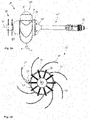
- FIGS. 1a-1c such as 2 show the basic structure of a possible embodiment of a pipe or duct probe 10.
- FIG. 1a a side view of the pipe or duct probe is shown.
- Fig. 1b A front view of the pipe or duct probe is shown.
- the 1c shows a perspective view of the pipe or duct probe 10 according to the invention.
- 2 shows a longitudinal section through the pipe or duct probe according to the invention according to FIG Figures 1a-1c .
- the tube or duct probe 10 has a motor 15 (see 2 ) on.
- the motor 15 itself has a motor housing and is located in a housing 20. In other words, the motor 15 is mounted in the housing 20, among other things.
- the motor 15 is a DC motor. The provision of a separate AC motor is no longer necessary due to the design of the pipe or duct probe 10 according to the invention.
- the motor 15 also has a motor shaft 18 (see FIG 2 ).
- a working medium 30 is directly connected to the motor shaft 18 .
- the connecting device 40 is used to connect the motor 15 to a cable (not shown here).
- a part of the connecting device 40, in particular the cap-shaped part 41 of the connecting device 40, can form part of the capsule-shaped housing 20.
- the other end of the connecting device 40 is used by means of a connecting piece 42 for connection to the indicated cable.
- a centering device base 51 of a centering device 50 is formed on the housing 20 or partially enclosing the housing 20 .
- the centerer base 51 is formed as an annular portion.
- a plurality of resilient members 55 are formed on the centerer base 51 .
- the resilient elements 55 are, as shown in Fig. 1b is shown, arranged in the circumferential direction of the housing 20 equally spaced from each other.
- the centerer base 51 may be interchangeably mounted on the housing 20 . It is possible that different centering devices 50 can be attached to the housing 20 . It is thus possible for different centering devices 50 to be pushed onto the housing 20 and connected to the housing 20 depending on the inner diameter of the pipe or duct.
- the elements 55 are preferably formed from a plastic material so that the radius of curvature of the resilient elements 55 can be reduced or increased.
- the resilient elements 55 can be bent in the direction of the central axis M, so that the outer diameter of the centering device 50 can be reduced.
- the resilient elements 55 do not have a constant width B in the direction of the longitudinal extent L. Rather, the resilient element 55 is designed in such a way that a type of convex surface is formed. On the one hand, this enables the pipe or duct probe 10 to be well centered in a pipe and, on the other hand, it allows for good bendability.
- the housing 20 has a sealing cover or a sealing cap 25 .
- This sealing cap 25 is formed in the area of the motor shaft 18 .
- a seal 35 is formed in the seal cap 25 .
- the seal 35 prevents an agent, in particular a resin-hardener mixture or other liquids, from penetrating into the motor 15 .
- the seal 35 is designed as a shaft sealing ring. With the help of a shaft sealing ring, the penetration of liquid into the housing 20, in particular into the motor 15, can be demonstrably prevented.
- the sealing cap 25 is preferably fastened to the rest of the housing 20 in such a way that the sealing 35 can be renewed or replaced.
- the sealing cap 25 is screwed onto another section of the housing 20 .
- the working means 30 shown is an application device, namely an application brush.
- an agent in particular a resin-hardener mixture, can be applied evenly to a pipe, in particular to a liner located in a pipe.
- the working means 30 shown or the application brush is connected directly to the motor shaft 18 . It is possible that a working medium, for example the application brush, is also indirectly connected to the motor shaft 18 . Springs, in particular spiral springs, are particularly suitable for this purpose.
- a recess 52 can also be seen. This recess 52 is used to attach, in particular to clamp, a static mixer (see 3 ).
- a system 60 according to the invention is shown.
- the system 60 includes a pipe or duct probe 10 according to the invention.
- a reel 70 is also shown.
- the reel 70 serves to store the cable 75 or the push cable.
- the system 60 also includes a control unit 71. This control unit 71 can be used to control the motor of the pipe or duct probe 10 accordingly.
- a static mixer 80 which is connected to the centering device 50 of the tube or duct probe 10 can also be seen. Accordingly, with the aid of the centering device 50, the static mixer 80 can be moved or transported exactly to a position to be processed or coated in a pipe.
- the cable 75 is connected to the pipe or duct probe 10 with the aid of the connecting device 40 .
- the two connecting pieces 42 and 76 form a type of quick connector.
- working means 30 is an application brush.
- the working means 30' is a cleaning device, namely a chain knocker.
- the working means 30" is also a cleaning device in the form of a sandpaper arrangement.
- the work equipment shown can, as shown in 3 is indicated to be exchanged variably.
- a direct attachment to the motor shaft 18 or an indirect attachment can be provided.
- the tools 30, 30' and 30" have corresponding fastening devices in this regard.
- the system 60 according to the invention is also shown. This representation makes it clear which components of the system are actually designed as belonging to the pipe or duct probe 10 .
- the cable 75 is preferably not to be referred to as belonging to the system 60. In fact, the cable 75 is not completely inside the tube 90.
Landscapes
- Engineering & Computer Science (AREA)
- Mechanical Engineering (AREA)
- General Engineering & Computer Science (AREA)
- Chemical & Material Sciences (AREA)
- Combustion & Propulsion (AREA)
- Life Sciences & Earth Sciences (AREA)
- Forests & Forestry (AREA)
- Cleaning In General (AREA)
- Investigating Or Analyzing Materials By The Use Of Magnetic Means (AREA)
- Investigating Or Analyzing Materials By The Use Of Ultrasonic Waves (AREA)
- Flexible Shafts (AREA)
Abstract
Description
- Die Erfindung betrifft eine Rohr- oder Kanalsonde zur Einführung in ein Rohr oder in einen Kanal, gemäß Patentanspruch 1. Außerdem betrifft die Erfindung ein System, umfassend eine erfindungsgemäße Rohr- oder Kanalsonde.
- In der Kanaltechnik sind derartige Reinigungs- und Beschichtungsgeräte bekannt, die an flexiblen Wellen angebrachte Werkzeuge, wie beispielsweise Bürsten oder Kettenschleudern, aufweisen. Die flexible Welle wird dabei durch einen außenliegenden Motor angetrieben. Diese Motoren müssen große Momente aufbringen können, um die entstehenden Reibmomente bewältigen zu können.
- Die Rotation einer derartigen flexiblen Welle bedingt Vibrationen, Reibung und hohe Drehmomente, was prinzipiell das Aufbringen einer Harzschicht verschlechtert bzw. den Reinigungsvorgang erschwert.
- Außerdem führen die genannten Vibrationen und Reibungen sowie die hohen Drehmomente zu einem erhöhten Verschleiß bei den bekannten Reinigungs- und Beschichtungsgeräten.
- Es ist somit Aufgabe der vorliegenden Erfindung, eine weiterentwickelte Rohr- oder Kanalsonde anzugeben, wobei die vorerwähnten Nachteile überwunden werden sollen.
- Des Weiteren ist es Aufgabe der Erfindung, ein weiterentwickeltes System mit einer weiterentwickelten Rohr- oder Kanalsonde anzugeben.
- Mithilfe eines weiterentwickelten Systems sowie mithilfe einer weiterentwickelten Rohr- oder Kanalsonde soll insbesondere eine Harzbeschichtung sowie eine Reinigung eines Rohrs oder eines Kanals einfacher durchführbar sein.
- Erfindungsgemäß wird die erläuterte Aufgabe im Hinblick auf eine Rohr- oder Kanalsonde durch den Gegenstand des Patentanspruches 1 und im Hinblick auf ein System durch den Gegenstand des Patentanspruches 13 gelöst. Die Unteransprüche umfassen mindestens zweckmäßige Ausgestaltungen und Weiterbildungen.
- Konkret wird die Aufgabe durch eine Rohr- oder Kanalsonde zur Einführung in ein Rohr oder in einen Kanal gelöst, wobei die erfindungsgemäße Rohr- oder Kanalsonde
- mindestens einen Motor,
- mindestens eine Motorwelle,
- mindestens ein mit der Motorwelle verbundenes Arbeitsmittel,
- eine Verbindungsvorrichtung zur Verbindung des Motors mit einem Kabel und
- mindestens eine mit einem Gehäuse verbundene Zentriervorrichtung aufweist.
- Erfindungsgemäß wird also eine derartige Rohr- oder Kanalsonde zur Verfügung gestellt, die selbst einen Motor aufweist. Der Antrieb eines Arbeitsmittels erfolgt somit durch einen Motor, der selbst als Teil einer Rohr- oder Kanalsonde ausgebildet ist.
- Als Rohr- oder Kanalsonde ist ein derartiges Bauteil zu verstehen, das in ein Rohr oder in einen Kanal eingeführt ist. Vorzugsweise ist die vollständige Rohr- oder Kanalsonde in einem Rohr oder in einem Kanal eingeführt bzw. einführbar.
- Da der Motor als Teil der Rohr- oder Kanalsonde ausgebildet ist, ist es nicht notwendig, eine flexible Welle vorzusehen, die einen externen Motor mit einem Arbeitsmittel verbindet. Vielmehr erfolgt der Antrieb der Motorwelle direkt im Rohr oder im Kanal.
- Es ist lediglich eine Verbindung zu einem Kabel, insbesondere einem Stromversorgungs- und/oder Datenkabel, notwendig, wobei das Kabel aus dem Rohr bzw. aus dem Kanal nach außen geführt ist. Mithilfe des Kabels findet eine elektrische Verbindung und/oder eine Datenverbindung des Motors mit einer vorzugsweise außerhalb des Rohrs oder des Kanals ausgebildeten Stromversorgungseinheit und/oder Steuereinheit statt.
- Mithilfe der Zentriervorrichtung ist es möglich, die Rohr- oder Kanalsonde in einem Rohr oder in einem Kanal zu führen. Mithilfe einer Zentriervorrichtung ist es möglich, eine gleichmäßige Beschichtung und/oder eine gleichmäßige Reinigung eines Rohrs oder eines Kanals zu ermöglichen. Mithilfe einer Zentriervorrichtung kann die Rohr- oder Kanalsonde auch durch gebogene Rohre oder Kanäle geführt werden.
- Die erfindungsgemäße Rohr- oder Kanalsonde wird als eine Vorrichtung zur Verfügung gestellt, die durch eine kompakte Bauweise sowie entsprechende Gruppierung einzelner Sondenbauteile einen flexiblen Einsatz in einem Rohr oder in einem Kanal ermöglicht.
- Der Begriff einer Sonde, nämlich einer Rohr- oder Kanalsonde, ist derart zu interpretieren, dass die zur Sonde zugehörigen Bauteile und Bauteilabschnitte in ein Rohr oder in einen Kanal eingeführt werden. Bauteile bzw. Bauteilabschnitte, die vollständig außerhalb des Rohrs oder des Kanals verbleiben, sind nicht zur Rohr- oder Kanalsonde zuzurechnen. Bei derartigen Bauteilen oder Bauteilabschnitten handelt es sich um Bauteile eines erfindungsgemäßen Systems, das eine erfindungsgemäße Rohr- oder Kanalsonde umfasst.
- Aufgrund der erfindungsgemäßen Ausbildung der Rohr- oder Kanalsonde wird eine gute Bogengängigkeit erzielt.
- Bei dem Motor der Rohr- oder Kanalsonde handelt es sich vorzugsweise um einen Gleichstrommotor (DC). Es ist möglich, Gleichstrommotoren zu verwenden, die in Drehzahlbereichen von 0 - 2.000 rpm betrieben werden können.
- Insbesondere ist eine Verbindung über ein Kabel zu einer Stromversorgung möglich, die eine 50 Hz-Stromversorgung zur Verfügung stellt. Mithilfe miniaturisierter Gleichstrommotoren ist eine Motorleistung von bis zu 200 W möglich. Mithilfe des Motors der Rohr- oder Kanalsonde kann ein Dauermoment von bis zu 250 mNm zur Verfügung gestellt werden.
- Die erfindungsgemäße Rohr- oder Kanalsonde weist eine Zentriervorrichtung auf, die mit einem Gehäuse verbunden ist. Bei dem Gehäuse kann es sich um ein Gehäuse der Rohr- oder Kanalsonde handeln. Des Weiteren ist es möglich, dass das Gehäuse ein Gehäuse oder ein Gehäuseabschnitt des Motors ist.
- Vorzugsweise ist der Motor zusammen mit einem Motorgehäuse in einem Gehäuse oder einem Gehäuseabschnitt der Rohr- oder Kanalsonde positioniert. Mit anderen Worten kann ein Motorgehäuse zumindest abschnittsweise von einem Gehäuse oder einem Gehäuseabschnitt der Rohr- oder Kanalsonde umgeben sein.
- Die Zentriervorrichtung kann zumindest abschnittsweise durch mehrere federnde Elemente gebildet sein oder mehrere federnde Elemente aufweisen.
- Vorzugsweise sind die federnden Elemente in Umfangsrichtung des Gehäuses beabstandet angeordnet. Besonders bevorzugt sind die federnden Elemente gleichmäßig in Umfangsrichtung des Gehäuses beabstandet angeordnet.
- Aufgrund der Ausbildung federnder Elemente ist es möglich, Unregelmäßigkeiten bzgl. Rohr- oder Kanaldurchmessern auszugleichen. Des Weiteren können Biegeabschnitte in Rohren und/oder Kanälen besser überwunden werden. Die federnden Elemente einer Zentriervorrichtung dienen vorzugsweise zur Anpassung der Zentriervorrichtung an unterschiedliche Durchmesser in Rohren und/oder Kanälen.
- Es ist möglich, dass die federnden Elemente als Bürstenelemente oder als Schenkelfeder oder als Formfeder oder als Zugfeder oder als federnde Druckstücke ausgebildet sind.
- Sofern die federnden Elemente als Bürstenelemente ausgebildet sind, sind diese vorzugsweise aus Kunststoff, insbesondere aus Nylon, gefertigt. Das Ausbilden von derartigen Bürstenelemente weist den Vorteil auf, dass einwirkende Kräfte auf die Rohr- oder Kanalsonde gefedert werden. Des Weiteren wird die Motorwelle weniger belastet. Das Ausbilden von Bürstenelementen als federnde Elemente weist des Weiteren den Vorteil hinsichtlich der Aufnahme von Vibrationen auf. Des Weiteren dient eine derartige Bürste als Verdrehschutz.
- Bei einer Schenkelfeder handelt es sich vorzugsweise um 90°-Schenkelfedern. Das heißt, dass die Schenkelfeder eine um 90° gebogene Form aufweist. Sofern die Rohr- oder Kanalsonde in das Rohr- und/oder den Kanal eingeführt wird, werden die Schenkelfedern zusammengedrückt und in Richtung der Mittelachse der Rohr- oder Kanalsonde gedrückt. Die Rohr- oder Kanalsonde wird aufgrund dessen zentriert. Bei Verringerung des Drucks auf die Schenkelfeder können die Schenkelfedern in eine ursprüngliche Position bzw. in Richtung der ursprünglichen Position der Schenkelfeder bewegt werden. Der Vorteil derartiger Schenkelfedern besteht darin, dass diese günstig herzustellen sind und für verschiedene Rohr- und/oder Kanaldurchmesser verwendbar sind.
- Eine Formfeder kann beispielsweise aus Federstahlblech hergestellt sein. Eine Formfeder erbringt die nötige Anpresskraft auf eine Rohr- und/oder Kanalwand, sobald die Rohr- oder Kanalsonde in einem Rohr und/oder in einem Kanal geführt wird. Die Form einer Formfeder ist variabel konstruierbar und auf den jeweiligen Anwendungszweck einstellbar. Eine derartige Form eines federnden Elementes weist ebenfalls den Vorteil auf, dass sich eine derartige Formfeder unterschiedlichen Rohrdimensionen anpassen kann.
- Bei einer Zugfeder handelt es sich vorzugsweise um zwei Gelenke, die mit einer Zugfeder miteinander verbunden werden. Sofern eine Zugfeder bzw. eine Rohr- und/oder Kanalsonde in einem Rohr und/oder Kanal befindlich ist, werden die Gelenke zueinander bezogen, so dass eine Anpresskraft auf die Rohr- und/oder Kanalwand erzeugt wird. Somit erfolgt eine Zentrierung der Rohr- oder Kanalsonde in dem Rohr und/oder in dem Kanal. Bei Ausbildung einer derartigen Zugfeder bzw. derartiger Zugfedern als Zentriervorrichtung wird der Vorteil erzielt, dass derartige federnde Elemente im Zusammenhang mit unterschiedlichen Rohr- und/oder Kanaldurchmessern verwendet werden können.
- Bei Ausbilden von federnden Druckstücken können diese insbesondere als federnde Kugeln ausgebildet sein.
- Als federnde Kugeln sind insbesondere derartige Kugeln zu verstehen, die in einer schalenförmigen Aufnahme gelagert sind, wobei die Kugeln federnd gelagert sind, so dass die Kugeln in Richtung der Schale gedrückt werden können, sofern die Kugeln mit entsprechendem Druck beaufschlagt werden. Derartige federnde Kugeln können also bei Verringerung eines Innendurchmessers eines Rohrs und/oder Kanals nach innen, d. h. in Richtung Mittelachse der Rohr- oder Kanalsonde gedrückt werden. Der Außendurchmesser der Zentriervorrichtung kann somit durch Eindrücken der federnden Kugeln in Richtung Mittelachse der Rohr- oder Kanalsonde verringert werden.
- Sofern der Innendurchmesser eines Rohrs und/oder eines Kanals wieder vergrößert wird, können die vorgespannten Kugeln wieder entspannt werden, so dass die Kugeln in den Lagerschalen nach außen gedrückt werden. Der Außendurchmesser der Zentriervorrichtung nimmt in diesem Fall wieder zu.
- Des Weiteren ist es möglich, dass die federnden Elemente turbinenschaufelartig ausgebildet sind.
- Als turbinenschaufelartig ausgebildete federnde Elemente sind derartige Elemente zu verstehen, die gebogen ausgebildet sind. Vorzugsweise weisen alle federnden Elemente bei einer derartigen Ausbildung der Erfindung in einem drucklosen Zustand einen gleichen Biegungsradius auf, wobei die federnden Elemente vorzugsweise aus einem derartigen Material gebildet sind, sodass der Biegeradius der federnden Elemente, die turbinenschaufelartig ausgebildet sind, in Abhängigkeit des Innendurchmessers des Rohrs und/oder des Kanals angepasst werden.
- Die turbinenschaufelartig ausgebildeten federnden Elemente können in Abhängigkeit des Innendurchmessers des Rohrs und/oder des Kanals stärker in Richtung der Mittelachse der Rohr- oder Kanalsonde angedrückt werden, so dass die turbinenschaufelartig ausgebildeten federnden Elemente insgesamt einen geringeren Außendurchmesser aufweisen. Sofern kein Druck mehr oder ein verringerter Druck auf die turbinenschaufelartig ausgebildeten federnden Elemente wirkt, können die federnden Elemente aufgrund der Entspannung nach außen, d. h. von der Mittelachse der Rohr- oder Kanalsonde wegweisend bewegt werden. Mit anderen Worten können die federnden Elemente aufgrund einer Rückstellkraft nach Verringerung eines entsprechenden Drucks auf die federnden Elemente in eine Ausgangsposition zurückgestellt werden, wobei die Ausgangsposition einen größeren Außendurchmesser aller federnden Elemente bzw. der Zentriervorrichtung bewirkt.
- In einer weiteren Ausführungsform der Erfindung ist es möglich, dass die federnden Elemente auf einer Zentriervorrichtungsbasis angeordnet sind. Die Zentriervorrichtungsbasis kann als Bauteil oder Abschnitt der Zentriervorrichtung ausgebildet sein.
- Vorzugsweise ist die Zentriervorrichtungsbasis ringförmig ausgebildet. Die Zentriervorrichtungsbasis kann insbesondere als ein derartiger Ring ausgebildet sein, der auf das Gehäuse der Rohr- oder Kanalsonde aufgeschoben ist oder zumindest einen Abschnitt des Gehäuses der Rohr- oder Kanalsonde bildet. Des Weiteren ist es möglich, dass der Motor (optional mit einem Motorgehäuse) in einer ringförmigen Zentriervorrichtungsbasis befindlich oder positioniert ist.
- Die Zentriervorrichtung kann in einer weiteren Ausführungsform der Erfindung gebogene Arme aufweisen. Die gebogenen Arme sind vorzugsweise in die gleiche Richtung gebogen. Die gebogenen Arme sind vorzugsweise derart flexibel ausgebildet, dass der Außendurchmesser der Zentriervorrichtung, der durch die gebogenen Arme gebildet wird, in Abhängigkeit der Position der gebogenen Arme vergrößert oder verkleinert werden kann.
- Das Arbeitsmittel der Rohr- oder Kanalsonde kann beispielsweise eine Applikationsvorrichtung sein. Beispielsweise kann das Arbeitsmittel eine Applikationsbürste sein. Mithilfe einer derartigen Applikationsvorrichtung, insbesondere mithilfe einer Applikationsbürste, ist es möglich, ein Mittel, insbesondere eine Harz-Härter-Mischung, gleichmäßig auf die Innenseite eines Rohrs und/oder Kanals, oder auf die Innenseite eines Verstärkungs- bzw. Reparationsschlauches (Liner) auftragen zu können. Mithilfe einer Applikationsvorrichtung, insbesondere mithilfe einer Applikationsbürste, kann ein Harz-Härter-Gemisch besonders gleichmäßig aufgetragen werden. Dies ist darauf zurückzuführen, dass das Arbeitsmittel direkt oder indirekt mit der Motorwelle des Motors verbunden ist und somit gedreht wird.
- Des Weiteren ist es möglich, dass das Arbeitsmittel eine Reinigungsvorrichtung ist. Mithilfe derartiger Reinigungsvorrichtungen können Verunreinigungen in einem Rohr und/oder einem Kanal beseitigt werden. Bei der Reinigungsvorrichtung kann es sich um einen Bürstenkopf und/oder eine Schleifpapier-Anordnung und/oder eine Kettenschleuder und/oder einen Blattbohrer und/oder einen Schaufelblattbohrer und/oder einen Schneidkopf und/oder einen Fräskopf handeln.
- Das Arbeitsmittel kann direkt mit der Motorwelle verbunden sein. Des Weiteren ist es möglich, dass das Arbeitsmittel indirekt mit der Motorwelle verbunden ist.
- Eine indirekte Verbindung mit der Motorwelle ist beispielsweise mittels eines Gelenks, insbesondere eines Kugelgelenks, möglich. Ein derartiges Kugelgelenk kann zwischen der Motorwelle und dem Arbeitsmittel ausgebildet sein.
- Eine weitere Möglichkeit hinsichtlich einer indirekten Verbindung eines Arbeitsmittels mit der Motorwelle betrifft die indirekte Verbindung mittels einer Feder. Vorzugsweise handelt es sich bei einer derartigen Feder um eine Metallfeder, die ausreichend lang ausgebildet ist, so dass die Rohr- oder Kanalsonde zusammen mit dem befestigten Arbeitsmittel auch durch gebogene Rohr- oder Kanalabschnitte geführt werden kann. Bei der Feder handelt es sich vorzugsweise um eine Spiralfeder.
- Insbesondere können die Mittel zur indirekten Verbindung des Arbeitsmittels mit der Motorwelle derart ausgebildet sein, dass das Arbeitsmittel einfach austauschbar ist. Dies ermöglicht es, die Rohr- oder Kanalsonde mit verschiedenen Arbeitsmitteln verwenden zu können. Das Mittel zur indirekten Verbindung des Arbeitsmittels mit der Motorwelle kann als Schnellverbinder ausgebildet sein.
- Eine Möglichkeit hinsichtlich des Ausbildens einer Zentriervorrichtungsbasis, insbesondere einer ringförmigen Zentriervorrichtungsbasis, besteht darin, dass die Zentriervorrichtungsbasis austauschbar an der Rohr- oder Kanalsonde angebracht werden kann. Insbesondere kann die Zentriervorrichtungsbasis austauschbar am Gehäuse ausgebildet sein.
- Es ist möglich, dass die Form, insbesondere der Durchmesser der Zentriervorrichtungsbasis an den jeweiligen Durchmesser des zu bearbeitenden Rohrs oder Kanals anpassbar ist. Hierzu können mehrere Zentriervorrichtungsbasen in einem Set zur Verfügung gestellt werden, so dass im Hinblick auf unterschiedliche Innendurchmesser von Rohren oder Kanälen eine Anpassung hinsichtlich der Abmaße bzw. Dimension der Zentriervorrichtung, insbesondere der Zentrierbasis, möglich ist.
- Bei der Verbindungsvorrichtung zur Verbindung des Motors mit einem Kabel kann es sich beispielsweise um einen Steckverbinder oder um ein Gelenk oder um eine Spiralfeder mit Anschlussstück handeln. Bei Ausbildung eines Gelenks kann es sich insbesondere um ein Kugelgelenk handeln. Das Ausbilden einer Verbindungsvorrichtung ist insbesondere dann notwendig oder vorteilhaft, sofern es sich bei dem mit der Rohr- oder Kanalsonde zu verbindenden Kabel um ein Schiebekabel handelt.
- Sofern die Verbindungsvorrichtung als Spiralfeder ausgebildet ist, wird der Vorteil erzielt, dass das Kabel geschützt werden kann und die Verbindungsvorrichtung sehr flexibel ist. Das Ausbilden eines Gelenks, insbesondere eines Kugelgelenks, hat den Vorteil, dass ein derartiges Gelenk nahezu frei bewegbar ist. Außerdem ist eine Verbindungsvorrichtung bei einer derartigen Ausführungsform der Erfindung äußerst stabil.
- Es ist möglich, dass die Rohr- oder Kanalsonde einen Temperatursensor aufweist. Mithilfe eines derartigen Temperatursensors kann beispielsweise der Vernetzungsgrad eines aufgetragenen Harz-Härter-Gemisches detektiert werden. Des Weiteren ist es möglich, dass die Rohr- oder Kanalsonde eine Kamera aufweist. Mithilfe einer derartigen Kamera ist es möglich, das Rohr oder den Kanal hinsichtlich eines etwaigen Verschmutzungsgrades zu untersuchen. Außerdem ist es mithilfe einer Kamera möglich, das Ergebnis eines Beschichtungsvorganges zu überprüfen.
- Die Rohr- oder Kanalsonde kann des Weiteren einen Mischer, insbesondere einen Statomischer, aufweisen. Dieser Mischer, insbesondere der Statomischer, kann vorzugsweise an der Zentriervorrichtung befestigt sein. Ein derartiger Mischer bzw. Statomischer dient insbesondere zur Mischung eines Harzes mit einem Härter. Die Mischung des Harzes mit dem Härter erfolgt vorzugsweise kurz vor dem Auftrag des Gemisches auf das Rohr, so dass die Mischung in baulicher Umgebung der Rohr- oder Kanalsonde, und eben nicht außerhalb des Rohres oder des Kanals erfolgt.
- Aufgrund der Ausbildung der erfindungsgemäßen Rohr- oder Kanalsonde ist es möglich, auf zwei nachteilige Bauteile bzw. Elemente bekannter Reinigungs- und Beschichtungsgeräte zu verzichten. Bei diesen Bauteilen handelt es sich zum einen um die flexible Welle bzw. Antriebswelle. Zum anderen handelt es sich um einen bislang notwendigen großen Wechselstrommotor. Aufgrund der kompakten Ausbildung der erfindungsgemäßen Rohr- oder Kanalsonde ist es erstmals möglich, sowohl einen Reinigungsvorgang als auch einen Beschichtungsvorgang mit einer derartigen Vorrichtung durchzuführen, die ohne Verwendung eines großen Wechselstrommotors (AC) betreibbar ist.
- Der zu verwendende Gleichstrommotor weist vorzugsweise ein maximales Kurzzeitdrehmoment von 245 mNm auf.
- Es ist möglich, dass zur Abdichtung des Motors die Motorwelle und/oder das Gehäuse des Motors und/oder das Gehäuse der Rohr- oder Kanalsonde mittels einer Dichtung, insbesondere mittels eines Dichtrings, besonders bevorzugt mittels eines Wellendichtrings, abgedichtet ist. Somit wird verhindert, dass ein aufzutragendes Mittel, insbesondere ein im Rohr aufzutragendes Harz-Härter-Gemisch, in die Rohr- oder Kanalsonde bzw. in den Motor eindringen kann.
- Ein Wellendichtring ist besonders günstig herzustellen und kann platzsparend in der Rohr- oder Kanalsonde platziert und verbaut werden.
- Der Wellendichtring ist vorzugsweise zwischen der Motorwelle und dem Gehäuse ausgebildet. Die Dichtung, insbesondere der Wellendichtring, ist derart konstruiert und im Gehäuse montiert, dass die Dichtung, insbesondere der Wellendichtring, möglichst einfach auswechselbar ist.
- In einer weiteren Ausführungsform der Erfindung kann die Rohr- oder Kanalsonde eine Temperaturregeleinheit aufweisen. Mithilfe der Temperaturregeleinheit kann die Temperatur in der Rohr- oder Kanalsonde geregelt werden, so dass die Eigenschaften, insbesondere die Viskosität, eines aufzutragenden Mittels, insbesondere eines aufzutragenden Harz-Härter-Gemisches, eingestellt werden kann.
- Das Gehäuse ist im Wesentlichen kapselförmig ausgebildet. Die Kapselform wird beispielsweise durch einen Dichtdeckel (bzw. eine Dichtungskappe), einen zylindrischen Abschnitt sowie einen Kabelanschluss gebildet. Der Dichtdeckel (Dichtungskappe) dient insbesondere dazu, einen Wellendichtring austauschbar im Gehäuse anordnen zu können.
- Sofern die federnden Elemente turbinenschaufelartig ausgebildet sind, sind die federnden Elemente hinsichtlich der Breite vorzugsweise über die Längserstreckung nicht gleichbleibend ausgebildet. Vielmehr ist vorzugsweise eine derartige Form der turbinenschaufelartig federnden Elemente ausgebildet, die in einer Seitenansicht eine konvexe Form bilden.
- Vorzugsweise weist die Zentriervorrichtung eine derartige Ausnehmung, insbesondere eine Aussparung, auf, so dass ein Mischer, insbesondere ein Statomischer, an der Zentriervorrichtung befestigt, insbesondere klemmend fixiert, werden kann.
- Ein weiterer Aspekt der Erfindung betrifft ein System, umfassend eine erfindungsgemäße Rohr- oder Kanalsonde sowie ein Kabel. Bei dem Kabel handelt es sich insbesondere um ein Schiebekabel. Des Weiteren umfasst das System eine Haspel, in der das Kabel, insbesondere das Schiebekabel, gelagert ist.
- Des Weiteren umfasst das System vorzugsweise eine Steuereinheit und/oder eine Stromversorgungseinheit, die vorzugsweise in oder an einem Gehäuse der Haspel angeordnet ist/sind.
- Mithilfe des erfindungsgemäßen Systems sind im Wesentlichen die gleichen Vorteile erzielbar, wie diese im Zusammenhang mit der erfindungsgemäßen Rohr- oder Kanalsonde angegeben sind.
- Die Erfindung wird nachstehend mit weiteren Einzelheiten unter Bezug auf die beigefügten Zeichnungen näher erläutert.
- In diesen zeigen:
- Fig. 1a-1c
- verschiedene Darstellungen hinsichtlich einer möglichen erfindungsgemäßen Ausführungsform einer Rohr- oder Kanalsonde;
- Fig. 2
- eine Längsschnittdarstellung durch die erfindungsgemäße Rohr- oder Kanalsonde gemäß
Fig. 1a-1c ; - Fig. 3
- ein erfindungsgemäßes System mit Darstellung möglicher Arbeitsmittel; und
- Fig. 4
- eine Darstellung des erfindungsgemäßen Systems mit einer in einem Rohr eingeführten erfindungsgemäßen Rohr- oder Kanalsonde.
- Im Folgenden werden für gleiche und gleich wirkende Teile dieselben Bezugsziffern verwendet.
- Die
Fig. 1a-1c sowieFig. 2 zeigen den prinzipiellen Aufbau einer möglichen Ausführungsform einer Rohr- oder Kanalsonde 10. - In
Fig. 1a ist eine Seitendarstellung der Rohr- oder Kanalsonde dargestellt. InFig. 1b ist eine Vorderansicht der Rohr- oder Kanalsonde dargestellt. DieFig. 1c zeigt eine perspektivische Ansicht auf die erfindungsgemäße Rohr- oder Kanalsonde 10.Fig. 2 zeigt eine Längsschnittdarstellung durch die erfindungsgemäße Rohr- oder Kanalsonde gemäßFig. 1a-1c . - Die Rohr- oder Kanalsonde 10 weist einen Motor 15 (siehe
Fig. 2 ) auf. Der Motor 15 weist selbst ein Motorgehäuse auf und befindet sich in einem Gehäuse 20. Im Gehäuse 20 ist mit anderen Worten unter anderem der Motor 15 gelagert. - Bei dem Motor 15 handelt es sich um einen Gleichstrommotor. Das Zur-Verfügung-Stellen eines separaten Wechselstrommotors ist aufgrund der erfindungsgemäßen Ausbildung der Rohr- oder Kanalsonde 10 nicht mehr notwendig.
- Der Motor 15 weist außerdem eine Motorwelle 18 auf (siehe
Fig. 2 ). Mit der Motorwelle 18 ist ein Arbeitsmittel 30 direkt verbunden. - Des Weiteren ist eine Verbindungsvorrichtung 40 dargestellt.
- Die Verbindungsvorrichtung 40 dient zur Verbindung des Motors 15 mit einem Kabel (hier nicht dargestellt). Ein Teil der Verbindungsvorrichtung 40, insbesondere der kappenförmige Teil 41 der Verbindungsvorrichtung 40, kann einen Teil des kapselförmigen Gehäuses 20 bilden. Das weitere Ende der Verbindungsvorrichtung 40 dient mittels eines Anschlussstückes 42 zur Verbindung mit dem angedeuteten Kabel.
- Auf dem Gehäuse 20 bzw. das Gehäuse 20 abschnittsweise umschließend, ist eine Zentriervorrichtungsbasis 51 einer Zentriervorrichtung 50 ausgebildet. Die Zentriervorrichtungsbasis 51 ist als ringförmiger Abschnitt ausgebildet. An der Zentriervorrichtungsbasis 51 sind mehrere federnde Elemente 55 ausgebildet. Die federnden Elemente 55 sind, wie dies in
Fig. 1b dargestellt ist, in Umfangsrichtung des Gehäuses 20 gleichmäßig beabstandet zueinander angeordnet. - Die Zentriervorrichtungsbasis 51 kann austauschbar am Gehäuse 20 angeordnet sein. Es ist möglich, dass unterschiedliche Zentriervorrichtungen 50 auf dem Gehäuse 20 angebracht werden können. So ist es möglich, dass abhängig vom Rohr- bzw. Kanalinnendurchmesser unterschiedliche Zentriervorrichtungen 50 auf das Gehäuse 20 aufgeschoben und mit dem Gehäuse 20 verbunden werden können.
- Es sind acht federnde Elemente 55 (siehe
Fig. 1b ) ausgebildet, die turbinenschaufelartig ausgebildet sind. Die Elemente 55 sind vorzugsweise aus einem Kunststoffmaterial gebildet, so dass der Biegungsradius der federnden Elemente 55 verkleinert oder vergrößert werden kann. Bei Einführen der Rohr- oder Kanalsonde 10 in ein Rohr, können die federnden Elemente 55 in Richtung der Mittelachse M gebogen werden, so dass der Außendurchmesser der Zentriervorrichtung 50 verkleinert werden kann. - Die federnden Elemente 55 weisen in Richtung der Längserstreckung L keine gleichbleibende Breite B auf. Vielmehr ist das federnde Element 55 derart ausgebildet, dass eine Art konvexe Fläche ausgebildet ist. Dies ermöglicht zum einen eine gute Zentrierung der Rohr- oder Kanalsonde 10 in einem Rohr, und zum anderen eine gute Bogengängigkeit.
- Das Gehäuse 20 weist einen Dichtungsdeckel bzw. eine Dichtungskappe 25 auf. Diese Dichtungskappe 25 ist im Bereich der Motorwelle 18 ausgebildet. In der Dichtungskappe 25 ist eine Dichtung 35 ausgebildet. Mithilfe der Dichtung 35 wird verhindert, dass ein Mittel, insbesondere ein Harz-Härter-Gemisch oder andere Flüssigkeiten, in der Motor 15 eindringen kann.
- Die Dichtung 35 ist vorliegend als Wellendichtring ausgebildet. Mithilfe eines Wellendichtrings kann das Eindringen von Flüssigkeit in das Gehäuse 20, insbesondere in den Motor 15 nachweislich verhindert werden.
- Vorzugsweise ist die Dichtungskappe 25 am restlichen Gehäuse 20 derart befestigt, dass die Dichtung 35 erneuert bzw. gewechselt werden kann. Beispielsweise ist die Dichtungskappe 25 auf einen weiteren Abschnitt des Gehäuses 20 aufgeschraubt.
- Bei dem dargestellten Arbeitsmittel 30 handelt es sich um eine Applikationsvorrichtung, nämlich um eine Applikationsbürste. Mithilfe einer derartigen Applikationsbürste kann ein Mittel, insbesondere ein Harz-Härter-Gemisch auf ein Rohr, insbesondere auf einen in einem Rohr befindlichen Liner gleichmäßig aufgetragen werden.
- Das dargestellte Arbeitsmittel 30 bzw. die Applikationsbürste, ist direkt mit der Motorwelle 18 verbunden. Es ist möglich, dass ein Arbeitsmittel, beispielsweise auch die Applikationsbürste indirekt auch mit der Motorwelle 18 verbunden ist. Hierzu eignen sich besonders Federn, insbesondere Spiralfedern.
- In
Fig. 1b ist des Weiteren eines Ausnehmung 52 zu erkennen. Diese Ausnehmung 52 dient zur Anbringung, insbesondere zur klemmenden Fixierung, eines Statomischers (sieheFig. 3 ). - In
Fig. 3 ist ein erfindungsgemäßes System 60 dargestellt. Das System 60 weist eine erfindungsgemäße Rohr- oder Kanalsonde 10 auf. Des Weiteren ist eine Haspel 70 dargestellt. Die Haspel 70 dient zur Lagerung des Kabels 75 bzw. des Schiebekabels. Das System 60 umfasst des Weiteren eine Steuereinheit 71. Mithilfe dieser Steuereinheit 71 kann der Motor der Rohr- oder Kanalsonde 10 entsprechend gesteuert werden. - Ebenfalls zu erkennen ist ein Statomischer 80, der mit der Zentriervorrichtung 50 der Rohr- oder Kanalsonde 10 verbunden ist. Demnach kann mithilfe der Zentriervorrichtung 50 der Statomischer 80 exakt an einer zu bearbeitenden bzw. zu beschichtenden Position in einem Rohr verfahren bzw. transportiert werden.
- Die Verbindung des Kabels 75 mit der Rohr- oder Kanalsonde 10 erfolgt mit Hilfe der Verbindungsvorrichtung 40. Ein Anschlussstück 76 des Kabels 75 wird mit Anschlussstück 42 der Verbindungsvorrichtung 40 verbunden. Die beiden Anschlussstücke 42 und 76 bilden eine Art Schnellverbinder.
- In
Fig. 3 sind alternative Ausführungsformen hinsichtlich des Arbeitsmittels 30 dargestellt. Beim Arbeitsmittel 30 handelt es sich um eine Applikationsbürste. - Das Arbeitsmittel 30' ist eine Reinigungsvorrichtung, nämlich eine Kettenschleuder. Das Arbeitsmittel 30" ist ebenfalls eine Reinigungsvorrichtung in Form einer Schleifpapieranordnung.
- Die dargestellten Arbeitsmittel können, wie dies in
Fig. 3 angedeutet ist, variabel ausgetauscht werden. Diesbezüglich kann eine direkte Befestigung an der Motorwelle 18 oder eine indirekte Befestigung vorgesehen sein. Die Arbeitsmittel 30, 30' und 30" weisen diesbezüglich entsprechende Befestigungsvorrichtungen auf. - In
Fig. 4 ist ebenfalls das erfindungsgemäße System 60 dargestellt. Anhand dieser Darstellung ist klar, welche Bauteile des Systems tatsächlich als zur Rohr- oder Kanalsonde 10 zugehörig ausgebildet sind. Das Kabel 75 ist vorzugsweise nicht als zum System 60 zugehörig zu bezeichnen. Das Kabel 75 befindet sich nämlich nicht vollständig im Rohr 90. - Es ist zu erkennen, dass aufgrund der erfindungsgemäßen Ausbildung der Rohr- oder Kanalsonde 10 ein Transport im Rohr 90 möglich ist, der unter anderem auch 90°-Biegungsabschnitte 95 aufweist.
- Abschließend sei angemerkt, dass sämtliche Merkmale, die in den Anmeldungsunterlagen und insbesondere in den abhängigen Ansprüchen genannt sind, trotz des vorgenommenen formalen Rückbezugs auf einen oder mehrere bestimmte Ansprüche, auch einzeln oder in beliebiger Kombination eigenständiger Schutz zukommen soll.
-
- 10
- Rohr- oder Kanalsonde
- 15
- Motor
- 18
- Motorwelle
- 20
- Gehäuse
- 25
- Dichtungskappe
- 30, 30', 30"
- Arbeitsmittel
- 35
- Dichtung
- 40
- Verbindungsvorrichtung
- 41
- kappenförmiger Teil
- 42
- Anschlussstück
- 50
- Zentriervorrichtung
- 51
- Zentriervorrichtungsbasis
- 55
- federndes Element
- 60
- System
- 70
- Haspel
- 71
- Steuereinheit
- 75
- Kabel
- 76
- Anschlussstück
- 80
- Statomischer
- 90
- Kanal
- 95
- Biegungsabschnitt
- M
- Mittelachse
- L
- Längserstreckung
- B
- Breite
Claims (15)
- Rohr- oder Kanalsonde (10) zur Einführung in ein Rohr (90) oder in einen Kanal,
dadurch gekennzeichnet, dass
die Rohr- oder Kanalsonde (10)- mindestens einen Motor (15),- mindestens eine Motorwelle (18),- mindestens ein mit der Motorwelle (18) verbundenes Arbeitsmittel (30, 30', 30"),- eine Verbindungsvorrichtung (40) zur Verbindung des Motors (15) mit einem Kabel (75) und- mindestens eine mit einem Gehäuse (20) verbundene Zentriervorrichtung (50)aufweist. - Rohr- oder Kanalsonde (10) nach Anspruch 1,
dadurch gekennzeichnet, dass
der Motor (15) ein Gleichstrommotor ist. - Rohr- oder Kanalsonde (10) nach Anspruch 1 oder 2,
dadurch gekennzeichnet, dass
die Zentriervorrichtung (50) zumindest abschnittsweise durch mehrere federnde Elemente (55), die in Umfangsrichtung des Gehäuses (20), vorzugsweise gleichmäßig, beabstandet angeordnet sind, gebildet ist. - Rohr- oder Kanalsonde (10) nach Anspruch 3,
dadurch gekennzeichnet, dass
die federnden Elemente (55) als Bürstenelemente oder als Schenkelfeder oder als Formfeder oder als Zugfeder oder als federnde Druckstücke, insbesondere federnde Kugeln, oder turbinenschaufelartig ausgebildet sind. - Rohr- oder Kanalsonde (10) nach Anspruch 3 oder 4,
dadurch gekennzeichnet, dass
die federnden Elemente (55) auf einer Zentriervorrichtungsbasis (51), die insbesondere ringförmig ausgebildet ist, angeordnet sind. - Rohr- oder Kanalsonde (10) nach einem der vorangegangenen Ansprüche,
dadurch gekennzeichnet, dass
die Zentriervorrichtung (50) gebogene Arme aufweist. - Rohr- oder Kanalsonde (10) nach einem der vorangegangenen Ansprüche,
dadurch gekennzeichnet, dass
das Arbeitsmittel (30) eine Applikationsvorrichtung, insbesondere eine Applikationsbürste, ist. - Rohr- oder Kanalsonde () nach einem der vorangegangenen Ansprüche,
dadurch gekennzeichnet, dass
das Arbeitsmittel (30', 30") eine Reinigungsvorrichtung, insbesondere ein Bürstenkopf und/oder eine Schleifpapier-Anordnung und/oder eine Kettenschleuder und/oder ein Blattbohrer und/oder ein Schaufelblattbohrer und/oder ein Schneidkopf und/oder ein Fräskopf, ist. - Rohr- oder Kanalsonde (10) nach einem der vorangegangenen Ansprüche,
dadurch gekennzeichnet, dass
das Arbeitsmittel (30, 30', 30") direkt mit der Motorwelle (18) oder indirekt mittels eines Gelenks, insbesondere eines Kugelgelenks, oder mittels einer Feder mit der Motorwelle (18) verbunden ist. - Rohr- oder Kanalsonde (10) nach einem der vorangegangenen Ansprüche,
dadurch gekennzeichnet, dass
die Verbindungsvorrichtung (40) als Steckverbinder oder als Spiralfeder mit Anschlussstück oder als Gelenk, insbesondere als Kugelgelenk, ausgebildet ist. - Rohr- oder Kanalsonde (10) nach einem der vorangegangenen Ansprüche,
gekennzeichnet durch
einen Temperatursensor und/oder eine Kamera. - Rohr- oder Kanalsonde (10) nach einem der vorangegangenen Ansprüche,
gekennzeichnet durch
einen Statomischer (80), der vorzugsweise an der Zentriervorrichtung (50) befestigt ist. - System (60) umfassend eine Rohr- oder Kanalsonde (10) nach einem der Ansprüche 1 bis 12 und ein Kabel (75).
- System (60) nach Anspruch 13,
gekennzeichnet durch
eine Haspel (70), in der das Kabel (75), insbesondere ein Schiebekabel, gelagert ist. - System (60) nach Anspruch 13 oder 14,
gekennzeichnet durch
eine Steuereinheit (71), die vorzugsweise in oder an einem Gehäuse der Haspel (70) angeordnet ist.
Priority Applications (11)
| Application Number | Priority Date | Filing Date | Title |
|---|---|---|---|
| ES20211890T ES2981755T3 (es) | 2020-12-04 | 2020-12-04 | Sonda y sistema con dicha sonda |
| HUE20211890A HUE066788T2 (hu) | 2020-12-04 | 2020-12-04 | Szonda, valamint rendszer ilyen szondával |
| EP20211890.7A EP4008947B1 (de) | 2020-12-04 | 2020-12-04 | Sonde und system mit einer solchen sonde |
| HRP20240909TT HRP20240909T1 (hr) | 2020-12-04 | 2020-12-04 | Sonda i sustav sa takvom sondom |
| PL20211890.7T PL4008947T3 (pl) | 2020-12-04 | 2020-12-04 | Sonda i układ z taką sondą |
| JP2023557486A JP7854686B2 (ja) | 2020-12-04 | 2021-11-30 | パイプまたはダクトプローブ、およびパイプまたはダクトプローブを備えるシステム |
| PCT/EP2021/083497 WO2022117540A1 (de) | 2020-12-04 | 2021-11-30 | Rohr- oder kanalsonde und system mit rohr- oder kanalsonde |
| AU2021390139A AU2021390139B2 (en) | 2020-12-04 | 2021-11-30 | Pipe- or duct probe and system comprising pipe- or duct probe |
| NZ800060A NZ800060B2 (en) | 2021-11-30 | Pipe or duct probe and system comprising pipe or duct probe | |
| US18/265,035 US12338939B2 (en) | 2020-12-04 | 2021-11-30 | Pipe or duct probe and system comprising pipe or duct probe |
| CA3201138A CA3201138A1 (en) | 2020-12-04 | 2021-11-30 | Pipe or duct probe and system comprising pipe or duct probe |
Applications Claiming Priority (1)
| Application Number | Priority Date | Filing Date | Title |
|---|---|---|---|
| EP20211890.7A EP4008947B1 (de) | 2020-12-04 | 2020-12-04 | Sonde und system mit einer solchen sonde |
Publications (3)
| Publication Number | Publication Date |
|---|---|
| EP4008947A1 true EP4008947A1 (de) | 2022-06-08 |
| EP4008947C0 EP4008947C0 (de) | 2024-04-10 |
| EP4008947B1 EP4008947B1 (de) | 2024-04-10 |
Family
ID=73726657
Family Applications (1)
| Application Number | Title | Priority Date | Filing Date |
|---|---|---|---|
| EP20211890.7A Active EP4008947B1 (de) | 2020-12-04 | 2020-12-04 | Sonde und system mit einer solchen sonde |
Country Status (9)
| Country | Link |
|---|---|
| US (1) | US12338939B2 (de) |
| EP (1) | EP4008947B1 (de) |
| AU (1) | AU2021390139B2 (de) |
| CA (1) | CA3201138A1 (de) |
| ES (1) | ES2981755T3 (de) |
| HR (1) | HRP20240909T1 (de) |
| HU (1) | HUE066788T2 (de) |
| PL (1) | PL4008947T3 (de) |
| WO (1) | WO2022117540A1 (de) |
Cited By (4)
| Publication number | Priority date | Publication date | Assignee | Title |
|---|---|---|---|---|
| CN115949830A (zh) * | 2022-12-29 | 2023-04-11 | 国家石油天然气管网集团有限公司 | 一种管道内运行装置的运动平衡装置以及管道内运行装置 |
| CN117816824A (zh) * | 2024-03-06 | 2024-04-05 | 淄博市特种设备检验研究院 | 一种压力容器封头旋压装置 |
| CN118218339A (zh) * | 2022-12-20 | 2024-06-21 | 中核武汉核电运行技术股份有限公司 | 一种适用微口径管道的运载装置 |
| DE102023117009A1 (de) | 2023-06-28 | 2025-01-02 | Ibak Helmut Hunger Gmbh & Co Kg | Vorrichtung für die Kanalrohrinspektion und/oder -sanierung, mit einem eine Arbeitsmaschine antreibenden Gleichstrommotor |
Citations (3)
| Publication number | Priority date | Publication date | Assignee | Title |
|---|---|---|---|---|
| US20170081834A1 (en) * | 2015-09-17 | 2017-03-23 | Osvaldo Benedid | Sewer line root cleaning and repair system |
| US9683360B1 (en) * | 2017-02-23 | 2017-06-20 | Daisval Vigoa | Automated pipe clearer |
| CN111089219A (zh) * | 2020-01-04 | 2020-05-01 | 单佳莹 | 一种船舶下水道润滑层保护装置 |
Family Cites Families (5)
| Publication number | Priority date | Publication date | Assignee | Title |
|---|---|---|---|---|
| US5813089A (en) * | 1996-10-15 | 1998-09-29 | Abatement Technologies, Inc. | Duct cleaning apparatus |
| KR102035697B1 (ko) | 2017-08-02 | 2019-10-23 | 에이엠티 주식회사 | 가스통 밸브 자동 개폐장치 및 그 방법 |
| US10363613B1 (en) | 2018-11-01 | 2019-07-30 | Hurricane Reinstatement Solutions, LLC | Pipeline reinstatement tool |
| CN109555933B (zh) * | 2019-01-28 | 2021-04-23 | 江苏科技大学 | 一种螺旋式内壁清扫机器人 |
| US11344930B2 (en) * | 2020-02-16 | 2022-05-31 | LSQ Manufacturing, Inc. | Self-centering conduit cleaning device with reduced axial length |
-
2020
- 2020-12-04 ES ES20211890T patent/ES2981755T3/es active Active
- 2020-12-04 HU HUE20211890A patent/HUE066788T2/hu unknown
- 2020-12-04 EP EP20211890.7A patent/EP4008947B1/de active Active
- 2020-12-04 PL PL20211890.7T patent/PL4008947T3/pl unknown
- 2020-12-04 HR HRP20240909TT patent/HRP20240909T1/hr unknown
-
2021
- 2021-11-30 CA CA3201138A patent/CA3201138A1/en active Pending
- 2021-11-30 AU AU2021390139A patent/AU2021390139B2/en active Active
- 2021-11-30 US US18/265,035 patent/US12338939B2/en active Active
- 2021-11-30 WO PCT/EP2021/083497 patent/WO2022117540A1/de not_active Ceased
Patent Citations (3)
| Publication number | Priority date | Publication date | Assignee | Title |
|---|---|---|---|---|
| US20170081834A1 (en) * | 2015-09-17 | 2017-03-23 | Osvaldo Benedid | Sewer line root cleaning and repair system |
| US9683360B1 (en) * | 2017-02-23 | 2017-06-20 | Daisval Vigoa | Automated pipe clearer |
| CN111089219A (zh) * | 2020-01-04 | 2020-05-01 | 单佳莹 | 一种船舶下水道润滑层保护装置 |
Cited By (7)
| Publication number | Priority date | Publication date | Assignee | Title |
|---|---|---|---|---|
| CN118218339A (zh) * | 2022-12-20 | 2024-06-21 | 中核武汉核电运行技术股份有限公司 | 一种适用微口径管道的运载装置 |
| CN115949830A (zh) * | 2022-12-29 | 2023-04-11 | 国家石油天然气管网集团有限公司 | 一种管道内运行装置的运动平衡装置以及管道内运行装置 |
| CN115949830B (zh) * | 2022-12-29 | 2024-06-25 | 国家石油天然气管网集团有限公司 | 一种管道内运行装置的运动平衡装置以及管道内运行装置 |
| DE102023117009A1 (de) | 2023-06-28 | 2025-01-02 | Ibak Helmut Hunger Gmbh & Co Kg | Vorrichtung für die Kanalrohrinspektion und/oder -sanierung, mit einem eine Arbeitsmaschine antreibenden Gleichstrommotor |
| DE102023117009B4 (de) | 2023-06-28 | 2025-12-18 | Ibak Helmut Hunger Gmbh & Co Kg | Vorrichtung für die Kanalrohrinspektion und/oder -sanierung, mit einem eine Arbeitsmaschine antreibenden Gleichstrommotor |
| CN117816824A (zh) * | 2024-03-06 | 2024-04-05 | 淄博市特种设备检验研究院 | 一种压力容器封头旋压装置 |
| CN117816824B (zh) * | 2024-03-06 | 2024-04-30 | 淄博市特种设备检验研究院 | 一种压力容器封头旋压装置 |
Also Published As
| Publication number | Publication date |
|---|---|
| US12338939B2 (en) | 2025-06-24 |
| US20240019070A1 (en) | 2024-01-18 |
| AU2021390139A9 (en) | 2024-04-18 |
| HRP20240909T1 (hr) | 2024-10-11 |
| CA3201138A1 (en) | 2022-06-09 |
| WO2022117540A1 (de) | 2022-06-09 |
| EP4008947C0 (de) | 2024-04-10 |
| HUE066788T2 (hu) | 2024-09-28 |
| AU2021390139A1 (en) | 2023-06-22 |
| NZ800060A (en) | 2025-10-31 |
| PL4008947T3 (pl) | 2024-08-19 |
| JP2024500560A (ja) | 2024-01-09 |
| EP4008947B1 (de) | 2024-04-10 |
| ES2981755T3 (es) | 2024-10-10 |
| AU2021390139B2 (en) | 2025-07-17 |
Similar Documents
| Publication | Publication Date | Title |
|---|---|---|
| WO2022117540A1 (de) | Rohr- oder kanalsonde und system mit rohr- oder kanalsonde | |
| EP3112682A2 (de) | Exzenterschneckenpumpe mit montage durch den hohlen rotor | |
| EP0716629B1 (de) | Werkzeugwechseleinrichtung für manipulatoren | |
| EP1567715B1 (de) | Schaberklingenhaltevorrichtung | |
| DE8913689U1 (de) | Rohrbildungsgerät | |
| DE4238700C2 (de) | Vorrichtung zur Befestigung von Verbindungselementen an Rohrleitungen | |
| DE102011103161A1 (de) | Reinigungsvorrichtung | |
| EP2752256B1 (de) | Vorrichtung zum Wellen eines Rohres | |
| EP3326727A2 (de) | Vorrichtung zur inspektion und reinigung eines leitungs- oder rohrabschnitts | |
| EP0029860A1 (de) | Zahnärztliches Handstück | |
| AT525867B1 (de) | Roboter zur grabenlosen Leitungs- und Schachtsanierung | |
| AT399201B (de) | Längsschneidarm für vortriebs- und abbauzwecke u.dgl. | |
| EP4283177A1 (de) | Antriebseinheit für einen molch | |
| EP3203132A1 (de) | Vorrichtung für arbeiten im inneren unbegehbarer rohre, rohrnetze, behälter und bauwerke mit wechselbaren arbeitswerkzeugen | |
| DE19804648C1 (de) | Einrichtung zum fernbetätigten Setzen und Festziehen einer Schraube | |
| DE102019131782A1 (de) | Motor-Leitungstrommelanordnung oder Motor-Schlauch-Trommelanordnung | |
| EP2058067B1 (de) | Vorrichtung mit einem Antrieb und einem Entgratwerkzeug sowie Entgratwerkzeug | |
| DE202021105145U1 (de) | Fräsroboter | |
| DE19543334A1 (de) | Verbindung drehmomentübertragender Maschinenteile | |
| DE102020005980A1 (de) | Steuerbarer Bohrkopf | |
| EP3162457B1 (de) | Handpresse | |
| DE202008000298U1 (de) | Schleifvorrichtung | |
| DE3610197C2 (de) | ||
| DE202024106129U1 (de) | Schraubwerkzeug-Drehmomentstütze und Schraubwerkzeugeinheit | |
| EP1769883A1 (de) | Vorrichtung zum Reinigen des Schaftes und der Anlagefläche eines Maschinen-Werkzeuges |
Legal Events
| Date | Code | Title | Description |
|---|---|---|---|
| REG | Reference to a national code |
Ref country code: HR Ref legal event code: TUEP Ref document number: P20240909T Country of ref document: HR |
|
| PUAI | Public reference made under article 153(3) epc to a published international application that has entered the european phase |
Free format text: ORIGINAL CODE: 0009012 |
|
| STAA | Information on the status of an ep patent application or granted ep patent |
Free format text: STATUS: THE APPLICATION HAS BEEN PUBLISHED |
|
| AK | Designated contracting states |
Kind code of ref document: A1 Designated state(s): AL AT BE BG CH CY CZ DE DK EE ES FI FR GB GR HR HU IE IS IT LI LT LU LV MC MK MT NL NO PL PT RO RS SE SI SK SM TR |
|
| STAA | Information on the status of an ep patent application or granted ep patent |
Free format text: STATUS: REQUEST FOR EXAMINATION WAS MADE |
|
| 17P | Request for examination filed |
Effective date: 20221208 |
|
| RBV | Designated contracting states (corrected) |
Designated state(s): AL AT BE BG CH CY CZ DE DK EE ES FI FR GB GR HR HU IE IS IT LI LT LU LV MC MK MT NL NO PL PT RO RS SE SI SK SM TR |
|
| GRAP | Despatch of communication of intention to grant a patent |
Free format text: ORIGINAL CODE: EPIDOSNIGR1 |
|
| STAA | Information on the status of an ep patent application or granted ep patent |
Free format text: STATUS: GRANT OF PATENT IS INTENDED |
|
| RIC1 | Information provided on ipc code assigned before grant |
Ipc: F16L 55/165 20060101ALN20231109BHEP Ipc: F16L 101/12 20060101ALN20231109BHEP Ipc: F16L 101/16 20060101ALN20231109BHEP Ipc: B08B 9/047 20060101ALI20231109BHEP Ipc: B08B 9/045 20060101ALI20231109BHEP Ipc: B08B 9/043 20060101ALI20231109BHEP Ipc: F16L 55/18 20060101ALI20231109BHEP Ipc: F16L 55/40 20060101AFI20231109BHEP |
|
| INTG | Intention to grant announced |
Effective date: 20231127 |
|
| P01 | Opt-out of the competence of the unified patent court (upc) registered |
Effective date: 20231207 |
|
| GRAS | Grant fee paid |
Free format text: ORIGINAL CODE: EPIDOSNIGR3 |
|
| GRAA | (expected) grant |
Free format text: ORIGINAL CODE: 0009210 |
|
| STAA | Information on the status of an ep patent application or granted ep patent |
Free format text: STATUS: THE PATENT HAS BEEN GRANTED |
|
| AK | Designated contracting states |
Kind code of ref document: B1 Designated state(s): AL AT BE BG CH CY CZ DE DK EE ES FI FR GB GR HR HU IE IS IT LI LT LU LV MC MK MT NL NO PL PT RO RS SE SI SK SM TR |
|
| REG | Reference to a national code |
Ref country code: GB Ref legal event code: FG4D Free format text: NOT ENGLISH |
|
| REG | Reference to a national code |
Ref country code: CH Ref legal event code: EP |
|
| REG | Reference to a national code |
Ref country code: DE Ref legal event code: R096 Ref document number: 502020007612 Country of ref document: DE |
|
| REG | Reference to a national code |
Ref country code: IE Ref legal event code: FG4D Free format text: LANGUAGE OF EP DOCUMENT: GERMAN |
|
| P04 | Withdrawal of opt-out of the competence of the unified patent court (upc) registered |
Effective date: 20240515 |
|
| U01 | Request for unitary effect filed |
Effective date: 20240510 |
|
| U07 | Unitary effect registered |
Designated state(s): AT BE BG DE DK EE FI FR IT LT LU LV MT NL PT SE SI Effective date: 20240521 |
|
| REG | Reference to a national code |
Ref country code: GR Ref legal event code: EP Ref document number: 20240401577 Country of ref document: GR Effective date: 20240819 |
|
| REG | Reference to a national code |
Ref country code: HU Ref legal event code: AG4A Ref document number: E066788 Country of ref document: HU |
|
| REG | Reference to a national code |
Ref country code: ES Ref legal event code: FG2A Ref document number: 2981755 Country of ref document: ES Kind code of ref document: T3 Effective date: 20241010 |
|
| REG | Reference to a national code |
Ref country code: HR Ref legal event code: T1PR Ref document number: P20240909 Country of ref document: HR |
|
| PG25 | Lapsed in a contracting state [announced via postgrant information from national office to epo] |
Ref country code: RS Free format text: LAPSE BECAUSE OF FAILURE TO SUBMIT A TRANSLATION OF THE DESCRIPTION OR TO PAY THE FEE WITHIN THE PRESCRIBED TIME-LIMIT Effective date: 20240710 |
|
| REG | Reference to a national code |
Ref country code: HR Ref legal event code: ODRP Ref document number: P20240909 Country of ref document: HR Payment date: 20241128 Year of fee payment: 5 |
|
| P05 | Withdrawal of opt-out of the competence of the unified patent court (upc) changed |
Free format text: CASE NUMBER: APP_27817/2024 Effective date: 20240521 |
|
| REG | Reference to a national code |
Ref country code: DE Ref legal event code: R097 Ref document number: 502020007612 Country of ref document: DE |
|
| PG25 | Lapsed in a contracting state [announced via postgrant information from national office to epo] |
Ref country code: SK Free format text: LAPSE BECAUSE OF FAILURE TO SUBMIT A TRANSLATION OF THE DESCRIPTION OR TO PAY THE FEE WITHIN THE PRESCRIBED TIME-LIMIT Effective date: 20240410 Ref country code: RO Free format text: LAPSE BECAUSE OF FAILURE TO SUBMIT A TRANSLATION OF THE DESCRIPTION OR TO PAY THE FEE WITHIN THE PRESCRIBED TIME-LIMIT Effective date: 20240410 |
|
| PG25 | Lapsed in a contracting state [announced via postgrant information from national office to epo] |
Ref country code: SM Free format text: LAPSE BECAUSE OF FAILURE TO SUBMIT A TRANSLATION OF THE DESCRIPTION OR TO PAY THE FEE WITHIN THE PRESCRIBED TIME-LIMIT Effective date: 20240410 |
|
| PG25 | Lapsed in a contracting state [announced via postgrant information from national office to epo] |
Ref country code: SM Free format text: LAPSE BECAUSE OF FAILURE TO SUBMIT A TRANSLATION OF THE DESCRIPTION OR TO PAY THE FEE WITHIN THE PRESCRIBED TIME-LIMIT Effective date: 20240410 Ref country code: SK Free format text: LAPSE BECAUSE OF FAILURE TO SUBMIT A TRANSLATION OF THE DESCRIPTION OR TO PAY THE FEE WITHIN THE PRESCRIBED TIME-LIMIT Effective date: 20240410 Ref country code: RO Free format text: LAPSE BECAUSE OF FAILURE TO SUBMIT A TRANSLATION OF THE DESCRIPTION OR TO PAY THE FEE WITHIN THE PRESCRIBED TIME-LIMIT Effective date: 20240410 |
|
| U20 | Renewal fee for the european patent with unitary effect paid |
Year of fee payment: 5 Effective date: 20241230 |
|
| PLBE | No opposition filed within time limit |
Free format text: ORIGINAL CODE: 0009261 |
|
| STAA | Information on the status of an ep patent application or granted ep patent |
Free format text: STATUS: NO OPPOSITION FILED WITHIN TIME LIMIT |
|
| 26N | No opposition filed |
Effective date: 20250113 |
|
| PG25 | Lapsed in a contracting state [announced via postgrant information from national office to epo] |
Ref country code: MC Free format text: LAPSE BECAUSE OF FAILURE TO SUBMIT A TRANSLATION OF THE DESCRIPTION OR TO PAY THE FEE WITHIN THE PRESCRIBED TIME-LIMIT Effective date: 20240410 |
|
| REG | Reference to a national code |
Ref country code: HR Ref legal event code: ODRP Ref document number: P20240909 Country of ref document: HR Payment date: 20251120 Year of fee payment: 6 |
|
| REG | Reference to a national code |
Ref country code: CH Ref legal event code: U11 Free format text: ST27 STATUS EVENT CODE: U-0-0-U10-U11 (AS PROVIDED BY THE NATIONAL OFFICE) Effective date: 20260101 |
|
| PGFP | Annual fee paid to national office [announced via postgrant information from national office to epo] |
Ref country code: IS Payment date: 20251229 Year of fee payment: 6 |
|
| PGFP | Annual fee paid to national office [announced via postgrant information from national office to epo] |
Ref country code: GB Payment date: 20251223 Year of fee payment: 6 |
|
| PGFP | Annual fee paid to national office [announced via postgrant information from national office to epo] |
Ref country code: NO Payment date: 20251218 Year of fee payment: 6 |
|
| PGFP | Annual fee paid to national office [announced via postgrant information from national office to epo] |
Ref country code: HR Payment date: 20251120 Year of fee payment: 6 Ref country code: HU Payment date: 20251128 Year of fee payment: 6 |
|
| PGFP | Annual fee paid to national office [announced via postgrant information from national office to epo] |
Ref country code: TR Payment date: 20251118 Year of fee payment: 6 Ref country code: GR Payment date: 20251218 Year of fee payment: 6 |
|
| PGFP | Annual fee paid to national office [announced via postgrant information from national office to epo] |
Ref country code: IE Payment date: 20251218 Year of fee payment: 6 Ref country code: CZ Payment date: 20251124 Year of fee payment: 6 |
|
| PGFP | Annual fee paid to national office [announced via postgrant information from national office to epo] |
Ref country code: PL Payment date: 20251121 Year of fee payment: 6 |
|
| U20 | Renewal fee for the european patent with unitary effect paid |
Year of fee payment: 6 Effective date: 20251219 |
|
| PG25 | Lapsed in a contracting state [announced via postgrant information from national office to epo] |
Ref country code: CY Free format text: LAPSE BECAUSE OF FAILURE TO SUBMIT A TRANSLATION OF THE DESCRIPTION OR TO PAY THE FEE WITHIN THE PRESCRIBED TIME-LIMIT; INVALID AB INITIO Effective date: 20201204 |
|
| PGFP | Annual fee paid to national office [announced via postgrant information from national office to epo] |
Ref country code: ES Payment date: 20260122 Year of fee payment: 6 |
|
| PGFP | Annual fee paid to national office [announced via postgrant information from national office to epo] |
Ref country code: CH Payment date: 20260101 Year of fee payment: 6 |