EP4008958B1 - Système de chambre de combustion de turbine à gaz et procédé de fonctionnement d'un système de chambre de combustion de turbine à gaz - Google Patents
Système de chambre de combustion de turbine à gaz et procédé de fonctionnement d'un système de chambre de combustion de turbine à gaz Download PDFInfo
- Publication number
- EP4008958B1 EP4008958B1 EP21204913.4A EP21204913A EP4008958B1 EP 4008958 B1 EP4008958 B1 EP 4008958B1 EP 21204913 A EP21204913 A EP 21204913A EP 4008958 B1 EP4008958 B1 EP 4008958B1
- Authority
- EP
- European Patent Office
- Prior art keywords
- combustion chamber
- mixed air
- flame tube
- chamber system
- air openings
- Prior art date
- Legal status (The legal status is an assumption and is not a legal conclusion. Google has not performed a legal analysis and makes no representation as to the accuracy of the status listed.)
- Active
Links
Images
Classifications
-
- F—MECHANICAL ENGINEERING; LIGHTING; HEATING; WEAPONS; BLASTING
- F23—COMBUSTION APPARATUS; COMBUSTION PROCESSES
- F23R—GENERATING COMBUSTION PRODUCTS OF HIGH PRESSURE OR HIGH VELOCITY, e.g. GAS-TURBINE COMBUSTION CHAMBERS
- F23R3/00—Continuous combustion chambers using liquid or gaseous fuel
- F23R3/02—Continuous combustion chambers using liquid or gaseous fuel characterised by the air-flow or gas-flow configuration
- F23R3/26—Controlling the air flow
-
- F—MECHANICAL ENGINEERING; LIGHTING; HEATING; WEAPONS; BLASTING
- F23—COMBUSTION APPARATUS; COMBUSTION PROCESSES
- F23R—GENERATING COMBUSTION PRODUCTS OF HIGH PRESSURE OR HIGH VELOCITY, e.g. GAS-TURBINE COMBUSTION CHAMBERS
- F23R2900/00—Special features of, or arrangements for continuous combustion chambers; Combustion processes therefor
- F23R2900/00001—Arrangements using bellows, e.g. to adjust volumes or reduce thermal stresses
Definitions
- the invention relates to a gas turbine combustion chamber system, in particular a micro gas turbine combustion chamber system, with a combustion chamber which has a longitudinally extending flame tube surrounding a flame zone, which is provided with a burner on its inlet side and is coupled or can be coupled to a turbine arrangement on its outlet side facing away from this and is provided with mixed air openings in an outlet section, with a pressure housing surrounding the combustion chamber, between the inside of which and the outside of the flame tube for supplying an air mass flow an inflow channel is formed leading from its outlet side to the inlet side, via which a mixed air portion is guided via the mixed air openings into the interior of the flame tube and a burner air portion is guided to the burner for combustion with the fuel flowing in, and with a control device via which the burner air portion supplied to the burner can be controlled by varying the mixed air portion depending on the load point of the turbine arrangement by adjusting the clear flow width of the mixed air openings.
- the GB 1 601 218 A shows a gas turbine combustion chamber system with mixed air openings on a flame tube, which are arranged in an inflow channel and whose flow width can be controlled mechanically by means of a valve via a pressure difference between the inflow channel and the outside air.
- the pressure in the supply channel acts via an opening on a piston arranged in a cylinder chamber and the outside pressure via an opening in a valve arrangement.
- a primary air inlet is controlled via another valve.
- This combustion chamber system therefore contains several coordinated, interacting valves with a relatively large number of individual system components, which require associated effort in terms of construction and maintenance and can cause malfunctions.
- the printed matter DE 19 45 921 A shows a gas turbine combustion chamber system in which mixed air openings on a flame tube in an air inflow channel are controlled in their flow width depending on a pressure difference between the pressure in the supply channel and the external environment.
- a jacket-shaped aperture can be moved by an actuator using a spring-loaded piston.
- a gas turbine combustor system and a method for operating a gas turbine combustor system are also described in the DE 41 20 831 A1
- hot gases from the combustion are generated from a compressed air stream.
- means are used which respond to a pressure difference between the combustion chamber itself and the compressed air.
- the means consist, for example, of spring components with a check valve and cause a bypass flow of part of the compressed air into a mixing zone on the outlet side of the flame zone or Combustion zone, for which the spring element of the means travels a distance depending on the pressure difference, which causes the relevant valve to open for a bypass flow of part of the compressed air into the mixing zone.
- the means of the control device which are constructed from several individual parts and individually assigned to the mixed air openings, for controlling the proportion of mixed air through the mixed air nozzles and thus also the proportion of burner air supplied to the burner, result in a relatively high level of construction effort, particularly in micro gas turbine combustion chamber systems, which also makes it difficult to set the fuel/air ratio in the burner or the combustion air ratio (air ratio ⁇ ) as reliably as possible for consistently low-emission and efficient combustion.
- This structure also involves a relatively high level of commissioning and maintenance effort and also an increased risk of failure.
- a gas turbine combustion chamber system and a method for operating it are also described in DE 43 04 201 A1
- a flame tube is surrounded concentrically by an outer casing at a distance, forming an annular air channel, and in turn encloses a combustion chamber.
- Compressed air is supplied via the air channel to a burner that projects through the outer casing and the flame tube into the combustion chamber, and mixed air nozzles are arranged on the circumference of the flame tube, which connect the air channel to the combustion chamber in order to introduce secondary air (mixed air) into the hot gas flow in the flame tube through the mixed air nozzles.
- the mixed air nozzles can be individually controlled to vary the mixed air proportion, since a previously tested solution with an adjustment ring common to all mixed air openings was considered disadvantageous there.
- the individual control components of the individual mixed air nozzles also result in the disadvantages mentioned above.
- the AT 6 537 E shows a displacement of an inner shell in a combustion chamber system according to the balance of the pneumatic force of a fuel pressure on the left side of a bottom and a pressure on the right side of the The force acting on the turbine side of the ground is caused by pressure built up there. A bellows-like structure is also shown.
- the EP 0 088 933 A1 shows a flame tube with an adjustment device in the form of an adjusting ring that surrounds the flame tube and by means of which the ratio of primary air quantity to secondary air quantity can be controlled depending on the load.
- the control is carried out by changing the flow cross sections of the primary air openings and the secondary air openings by means of rotation and/or axial displacement of the adjusting ring.
- the adjusting ring can be rotated by means of a motor, pneumatic or hydraulic drive.
- the JP H05 231645 A shows a three-part combustion chamber with a swirl body and secondary air openings for the addition of secondary combustion air. There is also an additional mixed air opening.
- the flow cross-sections of the secondary air openings are completely closed at idle and increase with increasing load. The flow cross-section of the mixed air opening remains constant over the load range.
- a disadvantage is that this is associated with increased commissioning effort and the various components and actuators result in a relatively high maintenance effort and an increased risk of failure, which leads to disadvantages, particularly in connection with micro gas turbine combustion chamber systems. with the aim of achieving low-emission, reliable combustion across the entire load range.
- the air mass flow through the turbo components varies greatly with the load point of the connected turbine arrangement over its load range or the required electrical power. There is also a greatly varying need for fuel power and thus fuel mass flow between minimum and full load.
- the respective ratio between air mass flow and fuel mass flow is not constant over the load range, but is shifted towards larger air mass flows at partial load.
- combustion chambers with fixed geometries are used in micro gas turbines. This results in an almost constant distribution over the entire load range between the air that is passed through the burner and the mixed air that is mixed in after the combustion zone in the flame tube.
- blocking the flow path to the burner leads to an increased pressure loss in the gas turbine combustion chamber system, in particular the micro gas turbine combustion chamber system, whereby the efficiency of the gas turbine, in particular the micro gas turbine, is adversely affected by components of the control device installed in the air path, such as throttles and valve components.
- the invention is based on the object of developing a gas turbine combustion chamber system, in particular a micro gas turbine combustion chamber system, in such a way that low-emission, reliable combustion is achieved over the entire load range of an associated turbine arrangement, and of providing a corresponding method.
- the invention provides that the control device has an adjusting device which responds to a pressure difference ( ⁇ p) between the inflow channel of the air and the environment of the combustion chamber system (usually atmospheric pressure), by means of which the clear flow width (flow cross section) of the mixed air openings can be reduced as a function of the load point, in particular continuously, with an increasing load point and increased with a decreasing load point.
- ⁇ p a pressure difference between the inflow channel of the air and the environment of the combustion chamber system
- the clear flow width of the mixed air openings is regulated as a function of the pressure difference ( ⁇ p) between the inflow channel and the external environment of the combustion chamber system by reducing the clear flow width with an increase in the load point of a coupled turbine arrangement and increasing it with a reduction in the load point.
- the pressure difference of the air in the inflow channel or an inflow pipe arranged there and the surroundings of the combustion chamber system around the pressure housing is used advantageously to regulate the burner air flow and thus the fuel/air ratio during combustion, whereby the air ratio can be maintained at different load points over the load range of a coupled turbine in order to achieve optimal exhaust gas values.
- Optimized control is also promoted by the fact that moderate temperatures of the installation point are present in the area of the control device and the detection of the pressure difference.
- the pressure gradient between the air in the feed channel and the environment correlates very well with the mass flow behavior required for combustion over the load range of the gas turbine.
- the actuating device to be mechanically constructed, and in particular passively operating, with the pressure difference being used indirectly or, preferably, directly as a drive source.
- the structure can be implemented with little effort using a few components, with high reliability and at low cost. If the pressure difference is used directly as a drive source, only one pressure-utilizing unit is required, with the mechanism being separated from extremely hot components of the flame tube, which contributes to the high reliability.
- the passively constructed control device in particular for the passively controlled portion of the mixed air flow, advantageously allows industrially available components to be used, and there is a low risk of failure as a result of low complexity and low maintenance costs.
- the flow channel can also be designed to be aerodynamically efficient and as unobstructed as possible in order to keep the pressure loss across the flow path of the air mass flow with the burner air portion small, which has a positive effect on the efficiency of the micro gas turbine combustion chamber in particular.
- the pressure difference can be fed indirectly via the converter unit to control another mechanical or other physical energy source in order to control the at least one actuator to change the clear flow width of the mixed air openings via the closing unit, whereby the pressure difference between the inflow channel and the environment is also used. If the pressure difference is used as a direct drive source for the actuator, a particularly simple structure results.
- the actuating device has a bellows, in particular made of metal, as at least one actuating element, which is firmly connected to the pressure housing with one of its front end areas and is connected to the closing unit comprising at least one closing element with its other front end area, which is spaced apart in the longitudinal direction, at a connecting section via at least one intermediate element, and the interior of the bellows is connected to the air inflow channel via at least one pressure compensation channel.
- a bellows in particular made of metal, is commercially available in various designs, with its deflection for adjusting the closing unit being brought about on the one hand by the pressure change depending on the load point and on the other hand, counteracting the pressure, by its inherent elastic restoring force.
- the required force parameters can be easily adapted to the respective combustion chamber system, e.g. by simulation and/or real tests, whereby other parameters to be taken into account, such as adjustment path, size and shape of the mixed air openings, can be determined in a suitable manner in each case.
- the closing unit is designed as a diaphragm which can be moved in translation and/or rotated in the circumferential direction by means of the actuator in the longitudinal direction of the flame tube, more or less closing the mixed air openings to vary the clear flow width or the flow cross-section.
- the mixed air openings can be easily varied by a simple adjustment mechanism depending on the pressure difference via the diaphragm, which is designed, for example, like a sleeve.
- the material of the closing unit and Their physical and mechanical properties can be suitably selected to achieve good functionality, e.g. with regard to good sliding properties at different temperatures of the flame tube.
- connecting section, the intermediate link and the closing unit are rigidly connected to one another also contributes to an advantageous structure.
- a further advantageous design of the combustion chamber system for the structure and function is that the pressure housing has a front wall section on its front side adjacent to the inlet side of the flame tube, on the outside of which facing the environment of the combustion chamber system several actuators are attached, and that several intermediate members running along the outside of the flame tube, in particular through the inflow channel, are designed as support struts or support rods, which are connected to the closing unit at their rear end region facing the outlet section of the flame tube and are connected to the actuators assigned to them via the connecting section at their front end region spaced apart from it.
- the front wall section of the pressure housing is formed, for example, by a burner flange of the installed burner.
- the closing unit designed as a baffle is designed as a ring baffle which runs around the flame tube in the area of the mixed air openings and extends axially over the flame tube with a constant inner cross section adapted to the outer cross section of the flame tube so that the clear flow width of the mixed air openings can be varied at least largely from completely open to partially (or not completely for functional reasons) closed via the maximum change in the pressure difference ( ⁇ p), whereby the flame tube has a constant outer cross section at least in the area of the mixed air openings and the displacement path of the ring baffle over an axial extension section.
- the flame tube has a plurality of mixed air openings in the circumferential direction, preferably equidistantly, spaced from one another, for example arranged in the same or in several planes perpendicular to the flame tube axis, and if the annular aperture has a plurality of aperture openings in the same or in several aperture planes perpendicular to the flame tube axis, which are spaced apart in the circumferential direction corresponding to the mixed air openings and can be brought largely or completely into line with the mixed air openings for complete or at least extensive opening thereof at a minimal pressure difference ( ⁇ p) and as largely or completely out of line as possible for complete or at least extensive closing of the mixed air openings at a maximum pressure difference ( ⁇ p), further good coordination options are achieved with regard to precise regulation of the air mass flow and low-emission combustion, for example.
- ⁇ p minimal pressure difference
- ⁇ p maximum pressure difference
- the geometric shape of the mixed air openings and the orifice openings can be selected depending on the combustion requirements at different load points of the turbine, such as size, shape and the resulting change in the clear flow width for the mixed air portion at the pressure differences present depending on the load point.
- Another advantageous design for a stable construction and reliable function is that the support rods in their position push the burner forward projecting section through holes made in the front wall section of the pressure housing into the interior of the bellows assigned to them and are attached to them via the respective connecting section.
- the holes can also advantageously serve as connecting openings for a pressure equalization connection. Additional pressure equalization holes between the inside of the bellows and the combustion chamber are also conceivable.
- a stable structure which also promotes reliable function, also consists in the fact that the holding rods are connected to a common circumferential stabilization ring, which forms a stop against the inside of the front wall section of the pressure housing when the aperture is adjusted in the direction of the minimum flow width or when the mixed air openings are closed.
- the adjustment of the aperture is also facilitated by the fact that the holding rods are guided in the direction of displacement by additional guide elements along the flame tube.
- control device operates passively, with a control mechanism responding to the pressure difference ( ⁇ p) in such a way that the pressure difference ( ⁇ p) drives an actuator and moves an orifice by which the clear flow width of the mixed air openings is varied depending on the load point over the load range in order to obtain optimum exhaust gas values.
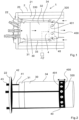
- Fig. 1 shows a combustion chamber system 1 (partially) in longitudinal section with an outer pressure housing 2, which is provided on the outside, towards the environment, on its front side with a front wall section that is formed by a burner flange 22, and is surrounded on the circumference by an outer wall 20 (outer shell, preferably cast body) and on the inside by insulation 21.
- a flame tube 34 is arranged, which is provided on its front side (inlet side) with a burner 31 and on its rear side facing away from the front side (outlet side) is connected or can be connected to a turbine arrangement (not shown) via a coupling section with coupling elements designed for this purpose.
- the space between the inside of the pressure housing 2 or the insulation 21 and the outside of the wall of the flame tube 34 is designed as an inflow channel 330 with a ring-shaped cross-section, in particular a circular cylindrical inflow channel, via which compressed air can be fed to the burner 31 from the rear (outlet side) of the combustion chamber system 1 in order to burn fuel introduced into it in a combustion chamber 30 inside the flame tube 34.
- an inflow pipe 33 between the inside of which and the outside of the flame tube 34 the air is fed to the burner 31, as shown in Fig. 1 indicated flow arrows.
- Mixing air openings 320 are arranged in the flame tube 34, preferably in an output section located behind the combustion chamber 30 towards the output side, in particular behind a flame zone 32 (combustion zone) towards the output side. These can be spaced equidistantly from one another in the direction of rotation, for example, and can be located in one or more cross-sectional planes perpendicular to the longitudinal extension of the flame tube 34, for example. Air from the compressed air mass flow introduced from the rear of the combustion chamber system 1 can be mixed into the combustion gases flowing from the input side to the output side inside the flame tube 34 via the mixing air openings 320.
- the combustion processes can be stabilized and optimized with regard to the exhaust gas values emitted via the mixed air portion branched off from the supplied air mass flow, whereby the burner air portion supplied to the burner is adjusted over the load range of the associated gas turbine depending on the load point to specify a suitable fuel/air ratio or the combustion air ratio (air ratio ⁇ ), as explained in more detail at the beginning.
- air ratio ⁇ combustion air ratio
- the clear flow width through the mixed air openings 320 is adjusted depending on the load point the gas turbine is varied by means of a control device via an adjusting device 4 depending on the pressure difference ⁇ p between the air pressure prevailing in the inflow channel 330 and the air pressure present in the environment of the combustion chamber system 1.
- the control device has an actuating device 4 with a displaceable closing unit 40, which, as shown in the Fig. 1 to 4 shown, is designed as an annular aperture 400, similar to a cuff, and is provided with aperture openings 401, which are designed in their position and size such that they can be brought into alignment with the mixed air openings 320 as completely as possible, so that their clear flow width is as completely or at least largely available for the passage of the mixed air portion.
- the mixed air openings 320 are designed as round mixed air bores; however, it is also conceivable to provide mixed air openings 320 with a different geometric shape, such as rectangular or non-symmetrical shapes, in order to suitably vary the clear flow width to achieve an optimal fuel/air ratio or air ratio ⁇ for combustion and optimal exhaust gas values at the respective load point of the gas turbine.
- the diaphragm is moved by means of retaining struts in the form of retaining rods 41 arranged outside along the flame tube 34 by means of the actuator 43, which is directly responds to the pressure difference ⁇ p and is designed in the present case as a bellows 430, in particular a metallic one, as a pressure-utilizing component.
- the closing unit thus consists of the movable cover 400, several holding rods 41, and several metal bellows 430, wherein the holding struts in their front section facing away from the cover 400 are additionally held in their relative position to one another by a circumferential stabilizing ring 42.
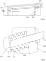
- the holding struts or holding rods 41 protrude with their front end section through through openings in the front wall section or the burner flange 22 into the interior of the respectively associated bellows 430, which are aligned and fastened on the outside of the burner flange 22 with their longitudinal axis parallel or concentric to the holding rods 41.
- the holding rods 41 are guided in the through-openings so that they can move and can also be guided by further guide elements on the outside of the flame tube 34.
- the front ends of the holding rods 41 are fastened inside the bellows 430 via connecting sections to their front end walls.
- the interior of the bellows 430 is in pressure equalization connection with the inflow channel 330 via connection openings 220 present in the burner flange 22 or the front wall section of the pressure housing 2, so that the respective (essentially static) pressure correlating with the load point of the gas turbine and the combustion prevails in the interior of the bellows 430 and thus the respective pressure difference ⁇ p dependent on the load point is established, by means of which the bellows 430, which is designed in particular as a metal bellows, is expanded against its spring force caused by its elasticity.
- the orifice 400 is displaced via the support rods 41 depending on the pressure difference ⁇ p and the clear flow width for the mixed air portion through the mixed air openings 320 is adjusted accordingly, so that as a result of the burner air portion, which is also regulated, the fuel/air ratio or the air ratio ⁇ is adapted to the power requirement of the gas turbine given by the respective load point, whereby the change the clear flow width of the mixed air openings is adjusted with regard to optimum exhaust gas values and combustion efficiency.
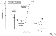
- the bellows 430 are made of a highly heat-resistant stainless steel and are designed to follow the pressure difference ⁇ p between the combustion chamber 30 or the inflow channel 330 and the environment over the load range of the gas turbine. Since the pressure level in the combustion chamber is lower at partial load than at full load, the bellows are expanded further at full load so that the orifice 400 slides in the direction of the burner 31. This means that the unobstructed area of the mixed air openings 320 is smaller at full load than at partial load and thus a smaller proportion of mixed air is passed through the mixed air openings 320. This increases the proportion of burner air at full load, which leads to a larger air ratio ⁇ .
- the stabilizing ring 42 which serves to stabilize the holding rods 41 so that they can only move axially (in the direction of the longitudinal axis of the flame tube 34), also serves in the present case to limit the expansion (the adjustment path) so that the bellows 430 cannot expand any further as soon as the stabilizing ring 42 abuts the inside of the burner flange 22.
Landscapes
- Engineering & Computer Science (AREA)
- Chemical & Material Sciences (AREA)
- Combustion & Propulsion (AREA)
- Mechanical Engineering (AREA)
- General Engineering & Computer Science (AREA)
Claims (11)
- Système de chambre de combustion de turbine à gaz (1), en particulier système de chambre de combustion de microturbine à gaz, comportant- une chambre de combustion (30) qui présente un tube de flamme (34) s'étendant longitudinalement et entourant une zone de flamme, lequel est pourvu d'un brûleur (31) sur son côté entrée et est accouplé ou peut être accouplé à un agencement de turbine sur son côté sortie opposé audit côté entrée et est pourvu d'ouvertures pour air mélangé (320) dans une section de sortie,- comportant un boîtier de pression (2) entourant la chambre de combustion (30), entre le côté intérieur de celle-ci et le côté extérieur du tube de flamme (34) pour l'amenée d'un flux massique d'air, un canal d'alimentation (330) menant du côté sortie dudit tube de flamme au côté entrée est formé, canal d'alimentation par l'intermédiaire duquel une portion pour air mélangé est guidée par l'intermédiaire des ouvertures pour air mélangé (320) à l'intérieur du tube de flamme (34) et une portion pour air de brûleur est amenée au brûleur (31) pour la combustion avec du combustible alimenté, et- comportant un dispositif de régulation par l'intermédiaire duquel la portion pour air de brûleur amenée au brûleur (31) peut être régulée en faisant varier la portion pour air mélangé en fonction du point de charge de l'agencement de turbine par réglage de la largeur de passage libre des ouvertures pour air mélangé (320),dans lequel- le dispositif de régulation présente un dispositif de réglage (4) réagissant à une différence de pression (Δp) entre le canal d'alimentation (330) de l'air et l'environnement du système de chambre de combustion (1), au moyen duquel dispositif de réglage la largeur de passage libre des ouvertures pour air mélangé (320) est réduite en fonction du point de charge, en particulier de manière continue, lorsque le point de charge augmente et est augmentée lorsque le point de charge diminue, et- le dispositif de réglage (4) est construit mécaniquement, dans lequel la différence de pression (Δp) indirectement ou, en particulier, directement comme source d'entraînement- en cas d'utilisation de la différence de pression (Δp) comme source d'entraînement indirecte, une unité de réglage comportant un capteur de pression, une unité de conversion et au moins un organe de réglage (43) entraîné par celle-ci existe, au moyen duquel organe de réglage la largeur de passage libre des ouvertures pour air mélangé (320) peut être variée par l'intermédiaire d'une unité de fermeture (40), et, en cas d'utilisation de la différence de pression (Δp) comme source d'entraînement directe, l'au moins un organe de réglage (43) est lui-même réalisé sous forme de capteur de pression au moyen duquel la largeur de passage libre des ouvertures pour air mélangé (320) peut être variée par l'intermédiaire de l'unité de fermeture (40) ;caractérisé en ce que- le dispositif de réglage (4) présente un soufflet (430) comme au moins un organe de réglage (43), en particulier en métal, qui est relié fixement au moyen d'une de ses zones d'extrémité frontales au boîtier de pression (2) et qui est relié au moyen de son autre zone d'extrémité frontale, espacée dans la direction longitudinale, sur une section de liaison par l'intermédiaire d'au moins un organe intermédiaire à l'unité de fermeture (40) comprenant au moins un élément de fermeture, et- l'intérieur du soufflet est relié au canal d'alimentation en air (330) par l'intermédiaire d'au moins un canal d'équilibrage de pression.
- Système de chambre de combustion selon la revendication 1,
caractérisé en ce
que l'unité de fermeture (40) est réalisée sous forme de déflecteur (400) qui peut être réglé dans la direction circonférentielle et/ou déplacé au moyen de l'organe de réglage (43) dans la direction longitudinale du tube de flamme (34) et recouvre plus ou moins les ouvertures pour air mélangé (320) pour la variation de la largeur de passage. - Système de chambre de combustion selon la revendication 1 ou 2,
caractérisé en ce
que la section de liaison, l'organe intermédiaire et l'unité de fermeture (40) sont reliés entre eux de manière rigide. - Système de chambre de combustion selon l'une des revendications précédentes,
caractérisé en ce
que le boîtier de pression (2) présente, sur sa face avant voisine du côté entrée du tube de flamme (34), une section de paroi avant sur la face extérieure de laquelle sont montés les organes de réglage (43), laquelle face extérieure est tournée vers l'environnement du système de chambre de combustion (1), et que plusieurs organes intermédiaires s'étendant le long du côté extérieur du tube de flamme (34), en particulier à travers le canal d'alimentation (330), sont réalisés sous forme de barres de maintien (41) qui sont reliées à l'unité de fermeture (40) au niveau de leur zone d'extrémité arrière tournée vers la section de sortie du tube de flamme (34) et qui sont reliées aux organes de réglage (43) qui leur sont associés par l'intermédiaire de leur zone d'extrémité avant espacée de celle-ci, par l'intermédiaire de la section de liaison. - Système de chambre de combustion selon l'une des revendications 2 à 4, caractérisé en ce
que l'unité de fermeture (40) arrangée sous forme de déflecteur (400) est réalisée sous forme de déflecteur annulaire qui circule autour du tube de flamme (34) dans la zone des ouvertures pour air mélangé (320) et s'étend axialement sur le tube de flamme (34) au moyen d'une section transversale intérieure constante, adaptée à la section transversale extérieure du tube de flamme (34), dans la mesure où la largeur de passage libre des ouvertures pour air mélangé (320) peut être variée au moins dans une large mesure de complètement ouverte à partiellement fermée par l'intermédiaire du changement maximal de la différence de pression (Δp), dans lequel le tube de flamme (34) possède une section transversale extérieure constante au moins dans la zone des ouvertures pour air mélangé (320) et de la course de déplacement du déflecteur annulaire sur une section d'extension axiale. - Système de chambre de combustion selon la revendication 5,
caractérisé en ce
que la surface extérieure du tube de flamme (34), au moins sur la section d'extension axiale dans la zone des ouvertures pour air mélangé (320) et de la course de déplacement, et la section transversale intérieure du déflecteur annulaire, sur son extension axiale, présentent une forme cylindrique circulaire. - Système de chambre de combustion selon la revendication 5 ou 6, caractérisé en ceque le tube de flamme (32) présente, dans la direction circonférentielle, plusieurs ouvertures pour air mélangé (320), de préférence espacées de manière équidistante les unes des autres, disposées par exemple dans le même plan ou dans plusieurs plans perpendiculaires à l'axe de tube de flamme, etque le déflecteur annulaire présente plusieurs ouvertures de déflecteur situées dans le même plan de déflecteur ou dans plusieurs plans de déflecteur perpendiculaires à l'axe de tube de flamme, lesquelles sont espacées dans le sens de circulation en fonction des ouvertures pour air mélangé (320) et, pour l'ouverture totale ou au moins dans une large mesure des ouvertures pour air mélangé (320), peuvent être amenées à coïncider dans une large mesure ou totalement avec celles-ci en cas de différence de pression (Δp) minimale et, pour la fermeture totale ou au moins dans une large mesure des ouvertures pour air mélangé (320), être amenées à ne pas coïncider dans une large mesure du possible ou totalement en cas de différence de pression (Δp) maximale.
- Système de chambre de combustion selon l'une des revendications 4 à 7, caractérisé en ce
que les barres de maintien (41) sont guidées dans leur section dépassant le brûleur (31) vers l'avant à travers des alésages pratiqués dans la section de paroi avant du boîtier de pression (2) à l'intérieur des soufflets (430) qui leur sont associés et sont fixées à ceux-ci par l'intermédiaire de la section de liaison respective. - Système de chambre de combustion selon l'une des revendications 4 à 8, caractérisé en ce
que les barres de maintien (41) sont reliées à une bague de stabilisation (42) circonférentielle commune qui forme une butée contre la face intérieure de la section de paroi avant du boîtier de pression (2) lors du réglage du déflecteur (400) en direction de la largeur de passage minimale ou de la fermeture des ouvertures pour air mélangé (320). - Système de chambre de combustion selon l'une des revendications 4 à 9, caractérisé en ce
que les barres de maintien (41) sont guidées à travers d'autres éléments de guidage le long du tube de flamme (34) dans le sens de déplacement. - Procédé permettant de faire fonctionner un système de chambre de combustion de turbine à gaz (1), en particulier un système de chambre de combustion de microturbine à gaz, selon l'une des revendications précédentes, dans lequel un flux massique d'air est amené par l'intermédiaire d'un canal d'alimentation (330) entre le côté intérieur d'un boîtier de pression (2) environnant et le côté extérieur d'un tube de flamme (34) depuis le côté sortie de celui-ci et est divisé, au moyen d'ouvertures pour air mélangé (320) disposées dans une section de sortie du tube de flamme (31), en une portion pour air mélangé qui est amenée derrière une zone de flamme à l'intérieur du tube de flamme (31) et en une portion pour air de brûleur qui est amenée à un brûleur (31) disposé sur le côté entrée du tube de flamme (34) pour la combustion avec du combustible, dans lequel le rapport combustible/air est régulé en faisant varier la largeur de passage libre des ouvertures pour air mélangé (320) au moyen d'un dispositif de régulation, dans lequel la largeur de passage libre des ouvertures pour air mélangé (320) est régulée en fonction de la différence de pression (Δp) entre le canal d'alimentation (330) et l'environnement extérieur du système de chambre de combustion (1) dans lequel la largeur de passage libre est réduite au moyen d'une augmentation du point de charge d'un agencement de turbine accouplé et est augmentée au moyen d'une réduction du point de charge, et dans lequel le dispositif de régulation fonctionne de manière passive, dans lequel un mécanisme de régulation traite la différence de pression (Δp) de telle sorte qu'un organe de réglage (43) est entraîné par la différence de pression (Δp) et qu'un déflecteur (400) est déplacé par celui-ci, par lequel la largeur de passage libre des ouvertures pour air mélangé (320) est variée en fonction du point de charge sur la plage de charge afin d'obtenir des valeurs d'échappement optimales.
Applications Claiming Priority (1)
| Application Number | Priority Date | Filing Date | Title |
|---|---|---|---|
| DE102020132494.4A DE102020132494B4 (de) | 2020-12-07 | 2020-12-07 | Gasturbinenbrennkammersystem und Verfahren zum Betreiben eines Gasturbinenbrennkammersystems |
Publications (3)
| Publication Number | Publication Date |
|---|---|
| EP4008958A1 EP4008958A1 (fr) | 2022-06-08 |
| EP4008958B1 true EP4008958B1 (fr) | 2024-12-11 |
| EP4008958C0 EP4008958C0 (fr) | 2024-12-11 |
Family
ID=78413751
Family Applications (1)
| Application Number | Title | Priority Date | Filing Date |
|---|---|---|---|
| EP21204913.4A Active EP4008958B1 (fr) | 2020-12-07 | 2021-10-27 | Système de chambre de combustion de turbine à gaz et procédé de fonctionnement d'un système de chambre de combustion de turbine à gaz |
Country Status (2)
| Country | Link |
|---|---|
| EP (1) | EP4008958B1 (fr) |
| DE (1) | DE102020132494B4 (fr) |
Families Citing this family (4)
| Publication number | Priority date | Publication date | Assignee | Title |
|---|---|---|---|---|
| CN117345414B (zh) * | 2022-06-28 | 2026-03-20 | 中国航发商用航空发动机有限责任公司 | 航空发动机燃烧室系统和航空发动机 |
| US20240318821A1 (en) * | 2023-03-20 | 2024-09-26 | General Electric Company | Combustor with a dilution passage |
| CN117053230B (zh) * | 2023-07-25 | 2025-08-08 | 中国船舶集团有限公司第七〇三研究所 | 一种带有空气调节系统的双燃料低排放燃气轮机燃烧室 |
| DE102024116456A1 (de) | 2024-06-12 | 2025-12-18 | Deutsches Zentrum für Luft- und Raumfahrt e.V. | Brennkammeranordnung und Verfahren zum Betreiben einer Brennkammeranordnung |
Citations (2)
| Publication number | Priority date | Publication date | Assignee | Title |
|---|---|---|---|---|
| DE1945921A1 (de) * | 1969-09-11 | 1971-03-25 | Motoren Turbinen Union | Brennkammer |
| GB1601218A (en) * | 1978-03-20 | 1981-10-28 | Rolls Royce | Combustion equipment for gas turbine engines |
Family Cites Families (15)
| Publication number | Priority date | Publication date | Assignee | Title |
|---|---|---|---|---|
| GB1257610A (fr) | 1967-11-10 | 1971-12-22 | ||
| US3952501A (en) | 1971-04-15 | 1976-04-27 | United Aircraft Of Canada Limited | Gas turbine control |
| FR2133832B1 (fr) | 1971-04-15 | 1975-10-24 | United Aircraft Canada | |
| US3869246A (en) * | 1973-12-26 | 1975-03-04 | Gen Motors Corp | Variable configuration combustion apparatus |
| US3927520A (en) * | 1974-02-04 | 1975-12-23 | Gen Motors Corp | Combustion apparatus with combustion and dilution air modulating means |
| FR2472082A1 (fr) * | 1979-12-19 | 1981-06-26 | France Etat | Perfectionnements apportes aux moteurs a combustion interne suralimentes, notamment aux moteurs diesel |
| DE3209135A1 (de) * | 1982-03-12 | 1983-09-15 | Kraftwerk Union AG, 4330 Mülheim | Gasturbinenbrennkammer |
| DE4120831A1 (de) | 1991-06-24 | 1993-01-07 | Asea Brown Boveri | Verfahren zum betrieb einer feuerungsanlage oder brennkammer |
| JP2914006B2 (ja) * | 1991-12-25 | 1999-06-28 | トヨタ自動車株式会社 | ガスタービンエンジンの燃焼器 |
| DE4304201A1 (de) | 1993-02-12 | 1994-08-18 | Abb Management Ag | Brennkammer für eine Gasturbine |
| FR2704628B1 (fr) | 1993-04-29 | 1995-06-09 | Snecma | Chambre de combustion comportant un système d'injection de comburant à géométrie variable. |
| DE19545311B4 (de) | 1995-12-05 | 2006-09-14 | Alstom | Verfahren zur Betrieb einer mit Vormischbrennern bestückten Brennkammer |
| EP2778531A1 (fr) | 2013-03-13 | 2014-09-17 | Siemens Aktiengesellschaft | Turbine à gaz avec combustion optimisée en charge partielle par réglage du débit d'air |
| JP2017032221A (ja) * | 2015-08-03 | 2017-02-09 | 三菱日立パワーシステムズ株式会社 | ガスタービン燃焼器 |
| US10712007B2 (en) * | 2017-01-27 | 2020-07-14 | General Electric Company | Pneumatically-actuated fuel nozzle air flow modulator |
-
2020
- 2020-12-07 DE DE102020132494.4A patent/DE102020132494B4/de active Active
-
2021
- 2021-10-27 EP EP21204913.4A patent/EP4008958B1/fr active Active
Patent Citations (2)
| Publication number | Priority date | Publication date | Assignee | Title |
|---|---|---|---|---|
| DE1945921A1 (de) * | 1969-09-11 | 1971-03-25 | Motoren Turbinen Union | Brennkammer |
| GB1601218A (en) * | 1978-03-20 | 1981-10-28 | Rolls Royce | Combustion equipment for gas turbine engines |
Also Published As
| Publication number | Publication date |
|---|---|
| EP4008958A1 (fr) | 2022-06-08 |
| DE102020132494B4 (de) | 2025-04-17 |
| DE102020132494A1 (de) | 2022-06-09 |
| EP4008958C0 (fr) | 2024-12-11 |
Similar Documents
| Publication | Publication Date | Title |
|---|---|---|
| EP4008958B1 (fr) | Système de chambre de combustion de turbine à gaz et procédé de fonctionnement d'un système de chambre de combustion de turbine à gaz | |
| DE2020416A1 (de) | Brennkammer fuer Gasturbinentriebwerke | |
| DE4220060C2 (de) | Einrichtung zur Betätigung einer den Durchsatz von Verbrennungsluft steuernden Dralleinrichtung eines Brenners für Gasturbinentriebwerke | |
| EP3559551B1 (fr) | Dispositif de mélange et tête de brûleur pour un brûleur à émission de nox réduite | |
| CH702825A2 (de) | Turbinenbrennkammer-Einsatzanordnung. | |
| EP1621811B1 (fr) | Procédé de fonctionnement pour un dispositif de combustion | |
| EP3004743B1 (fr) | Brûleur pour une turbine à gaz et procédé de réduction d'oscillations thermoacoustiques dans une turbine à gaz | |
| EP2103876A2 (fr) | Brûleur pour turbine à gaz avec mécanisme de rinçage pour les buses à combustible | |
| DE60027356T2 (de) | Brennkammer für eine Gasturbine | |
| DE3109269C2 (fr) | ||
| EP2071156B1 (fr) | Système de distribution de carburant d'une turbine à gaz avec ensemble brûleur à plusieurs étages | |
| DE60225411T2 (de) | Flammrohr oder Bekleidung für die Brennkammer einer Gasturbine mit niedriger Schadstoffemission | |
| EP4008955B1 (fr) | Dispositif et procédé d'alimentation en air de combustion et de récirculation des gaz d'échappement pour un brûleur | |
| EP2264370B1 (fr) | Agencement de brûleur pour une installation de combustion destinée à la combustion de combustibles fluidiques et procédé de fonctionnement d'un tel agencement de brûleur | |
| WO2011117042A1 (fr) | Brûleur pour la stabilisation de la combustion d'une turbine à gaz | |
| DE4010471C2 (fr) | ||
| DE102017120370B4 (de) | Brennerkopf, Brennersystem und Verfahren zum Betreiben des Brennersystems | |
| EP2409086A1 (fr) | Arrangement de brûleur | |
| EP3926238B1 (fr) | Module d'une turbine à gaz pourvu de dérivation d'air de la chambre de combustion | |
| EP1724526A1 (fr) | Coquille de turbine à gaz, turbine à gaz et procédé de démarrage et d'arrêt d'une turbine à gaz | |
| CH250563A (de) | Rückstossantrieb für Fahrzeuge, insbesondere Flugzeuge. | |
| EP2271876B1 (fr) | Dispositif de brûleur pour combustibles fluides et procédé de fabrication du dispositif de brûleur | |
| DE4304201A1 (de) | Brennkammer für eine Gasturbine | |
| DE10345137B4 (de) | Verfahren zum Betrieb einer Brennstoffeinspritzvorrichtung sowie eine Brennstoffeinspritzvorrichtung zur Durchführung des Verfahrens | |
| EP2808612A1 (fr) | Chambre de combustion d'une turbine à gaz avec injection tangentielle comme injection pauvre tardive |
Legal Events
| Date | Code | Title | Description |
|---|---|---|---|
| PUAI | Public reference made under article 153(3) epc to a published international application that has entered the european phase |
Free format text: ORIGINAL CODE: 0009012 |
|
| STAA | Information on the status of an ep patent application or granted ep patent |
Free format text: STATUS: THE APPLICATION HAS BEEN PUBLISHED |
|
| AK | Designated contracting states |
Kind code of ref document: A1 Designated state(s): AL AT BE BG CH CY CZ DE DK EE ES FI FR GB GR HR HU IE IS IT LI LT LU LV MC MK MT NL NO PL PT RO RS SE SI SK SM TR |
|
| STAA | Information on the status of an ep patent application or granted ep patent |
Free format text: STATUS: REQUEST FOR EXAMINATION WAS MADE |
|
| 17P | Request for examination filed |
Effective date: 20221208 |
|
| RBV | Designated contracting states (corrected) |
Designated state(s): AL AT BE BG CH CY CZ DE DK EE ES FI FR GB GR HR HU IE IS IT LI LT LU LV MC MK MT NL NO PL PT RO RS SE SI SK SM TR |
|
| STAA | Information on the status of an ep patent application or granted ep patent |
Free format text: STATUS: EXAMINATION IS IN PROGRESS |
|
| 17Q | First examination report despatched |
Effective date: 20230414 |
|
| GRAP | Despatch of communication of intention to grant a patent |
Free format text: ORIGINAL CODE: EPIDOSNIGR1 |
|
| STAA | Information on the status of an ep patent application or granted ep patent |
Free format text: STATUS: GRANT OF PATENT IS INTENDED |
|
| INTG | Intention to grant announced |
Effective date: 20240801 |
|
| GRAS | Grant fee paid |
Free format text: ORIGINAL CODE: EPIDOSNIGR3 |
|
| GRAA | (expected) grant |
Free format text: ORIGINAL CODE: 0009210 |
|
| STAA | Information on the status of an ep patent application or granted ep patent |
Free format text: STATUS: THE PATENT HAS BEEN GRANTED |
|
| AK | Designated contracting states |
Kind code of ref document: B1 Designated state(s): AL AT BE BG CH CY CZ DE DK EE ES FI FR GB GR HR HU IE IS IT LI LT LU LV MC MK MT NL NO PL PT RO RS SE SI SK SM TR |
|
| REG | Reference to a national code |
Ref country code: GB Ref legal event code: FG4D Free format text: NOT ENGLISH |
|
| REG | Reference to a national code |
Ref country code: CH Ref legal event code: EP |
|
| REG | Reference to a national code |
Ref country code: DE Ref legal event code: R096 Ref document number: 502021006069 Country of ref document: DE |
|
| REG | Reference to a national code |
Ref country code: IE Ref legal event code: FG4D Free format text: LANGUAGE OF EP DOCUMENT: GERMAN |
|
| U01 | Request for unitary effect filed |
Effective date: 20241213 |
|
| U07 | Unitary effect registered |
Designated state(s): AT BE BG DE DK EE FI FR IT LT LU LV MT NL PT RO SE SI Effective date: 20250103 |
|
| PG25 | Lapsed in a contracting state [announced via postgrant information from national office to epo] |
Ref country code: HR Free format text: LAPSE BECAUSE OF FAILURE TO SUBMIT A TRANSLATION OF THE DESCRIPTION OR TO PAY THE FEE WITHIN THE PRESCRIBED TIME-LIMIT Effective date: 20241211 |
|
| PG25 | Lapsed in a contracting state [announced via postgrant information from national office to epo] |
Ref country code: ES Free format text: LAPSE BECAUSE OF FAILURE TO SUBMIT A TRANSLATION OF THE DESCRIPTION OR TO PAY THE FEE WITHIN THE PRESCRIBED TIME-LIMIT Effective date: 20241211 |
|
| PG25 | Lapsed in a contracting state [announced via postgrant information from national office to epo] |
Ref country code: NO Free format text: LAPSE BECAUSE OF FAILURE TO SUBMIT A TRANSLATION OF THE DESCRIPTION OR TO PAY THE FEE WITHIN THE PRESCRIBED TIME-LIMIT Effective date: 20250311 |
|
| PG25 | Lapsed in a contracting state [announced via postgrant information from national office to epo] |
Ref country code: GR Free format text: LAPSE BECAUSE OF FAILURE TO SUBMIT A TRANSLATION OF THE DESCRIPTION OR TO PAY THE FEE WITHIN THE PRESCRIBED TIME-LIMIT Effective date: 20250312 |
|
| PG25 | Lapsed in a contracting state [announced via postgrant information from national office to epo] |
Ref country code: RS Free format text: LAPSE BECAUSE OF FAILURE TO SUBMIT A TRANSLATION OF THE DESCRIPTION OR TO PAY THE FEE WITHIN THE PRESCRIBED TIME-LIMIT Effective date: 20250311 |
|
| PG25 | Lapsed in a contracting state [announced via postgrant information from national office to epo] |
Ref country code: SM Free format text: LAPSE BECAUSE OF FAILURE TO SUBMIT A TRANSLATION OF THE DESCRIPTION OR TO PAY THE FEE WITHIN THE PRESCRIBED TIME-LIMIT Effective date: 20241211 |
|
| PG25 | Lapsed in a contracting state [announced via postgrant information from national office to epo] |
Ref country code: PL Free format text: LAPSE BECAUSE OF FAILURE TO SUBMIT A TRANSLATION OF THE DESCRIPTION OR TO PAY THE FEE WITHIN THE PRESCRIBED TIME-LIMIT Effective date: 20241211 |
|
| PG25 | Lapsed in a contracting state [announced via postgrant information from national office to epo] |
Ref country code: IS Free format text: LAPSE BECAUSE OF FAILURE TO SUBMIT A TRANSLATION OF THE DESCRIPTION OR TO PAY THE FEE WITHIN THE PRESCRIBED TIME-LIMIT Effective date: 20250411 |
|
| PG25 | Lapsed in a contracting state [announced via postgrant information from national office to epo] |
Ref country code: SK Free format text: LAPSE BECAUSE OF FAILURE TO SUBMIT A TRANSLATION OF THE DESCRIPTION OR TO PAY THE FEE WITHIN THE PRESCRIBED TIME-LIMIT Effective date: 20241211 |
|
| PG25 | Lapsed in a contracting state [announced via postgrant information from national office to epo] |
Ref country code: CZ Free format text: LAPSE BECAUSE OF FAILURE TO SUBMIT A TRANSLATION OF THE DESCRIPTION OR TO PAY THE FEE WITHIN THE PRESCRIBED TIME-LIMIT Effective date: 20241211 |
|
| PLBE | No opposition filed within time limit |
Free format text: ORIGINAL CODE: 0009261 |
|
| STAA | Information on the status of an ep patent application or granted ep patent |
Free format text: STATUS: NO OPPOSITION FILED WITHIN TIME LIMIT |
|
| REG | Reference to a national code |
Ref country code: CH Ref legal event code: L10 Free format text: ST27 STATUS EVENT CODE: U-0-0-L10-L00 (AS PROVIDED BY THE NATIONAL OFFICE) Effective date: 20251022 |
|
| U20 | Renewal fee for the european patent with unitary effect paid |
Year of fee payment: 5 Effective date: 20250915 |
|
| REG | Reference to a national code |
Ref country code: CH Ref legal event code: U11 Free format text: ST27 STATUS EVENT CODE: U-0-0-U10-U11 (AS PROVIDED BY THE NATIONAL OFFICE) Effective date: 20251101 |
|
| 26N | No opposition filed |
Effective date: 20250912 |
|
| PGFP | Annual fee paid to national office [announced via postgrant information from national office to epo] |
Ref country code: CH Payment date: 20251101 Year of fee payment: 5 |