EP4008959B1 - Vorrichtung fur einen turbinenmotor umfassend eine brennstoffprallplate - Google Patents
Vorrichtung fur einen turbinenmotor umfassend eine brennstoffprallplate Download PDFInfo
- Publication number
- EP4008959B1 EP4008959B1 EP21211805.3A EP21211805A EP4008959B1 EP 4008959 B1 EP4008959 B1 EP 4008959B1 EP 21211805 A EP21211805 A EP 21211805A EP 4008959 B1 EP4008959 B1 EP 4008959B1
- Authority
- EP
- European Patent Office
- Prior art keywords
- fuel
- nozzle
- splash plate
- turbine engine
- degrees
- Prior art date
- Legal status (The legal status is an assumption and is not a legal conclusion. Google has not performed a legal analysis and makes no representation as to the accuracy of the status listed.)
- Active
Links
Images




Classifications
-
- F—MECHANICAL ENGINEERING; LIGHTING; HEATING; WEAPONS; BLASTING
- F23—COMBUSTION APPARATUS; COMBUSTION PROCESSES
- F23R—GENERATING COMBUSTION PRODUCTS OF HIGH PRESSURE OR HIGH VELOCITY, e.g. GAS-TURBINE COMBUSTION CHAMBERS
- F23R3/00—Continuous combustion chambers using liquid or gaseous fuel
- F23R3/28—Continuous combustion chambers using liquid or gaseous fuel characterised by the fuel supply
-
- F—MECHANICAL ENGINEERING; LIGHTING; HEATING; WEAPONS; BLASTING
- F23—COMBUSTION APPARATUS; COMBUSTION PROCESSES
- F23R—GENERATING COMBUSTION PRODUCTS OF HIGH PRESSURE OR HIGH VELOCITY, e.g. GAS-TURBINE COMBUSTION CHAMBERS
- F23R3/00—Continuous combustion chambers using liquid or gaseous fuel
- F23R3/28—Continuous combustion chambers using liquid or gaseous fuel characterised by the fuel supply
- F23R3/286—Continuous combustion chambers using liquid or gaseous fuel characterised by the fuel supply having fuel-air premixing devices
-
- F—MECHANICAL ENGINEERING; LIGHTING; HEATING; WEAPONS; BLASTING
- F23—COMBUSTION APPARATUS; COMBUSTION PROCESSES
- F23D—BURNERS
- F23D14/00—Burners for combustion of a gas, e.g. of a gas stored under pressure as a liquid
- F23D14/46—Details
- F23D14/48—Nozzles
- F23D14/58—Nozzles characterised by the shape or arrangement of the outlet or outlets from the nozzle, e.g. of annular configuration
-
- F—MECHANICAL ENGINEERING; LIGHTING; HEATING; WEAPONS; BLASTING
- F23—COMBUSTION APPARATUS; COMBUSTION PROCESSES
- F23D—BURNERS
- F23D14/00—Burners for combustion of a gas, e.g. of a gas stored under pressure as a liquid
- F23D14/46—Details
- F23D14/62—Mixing devices; Mixing tubes
- F23D14/64—Mixing devices; Mixing tubes with injectors
-
- F—MECHANICAL ENGINEERING; LIGHTING; HEATING; WEAPONS; BLASTING
- F23—COMBUSTION APPARATUS; COMBUSTION PROCESSES
- F23R—GENERATING COMBUSTION PRODUCTS OF HIGH PRESSURE OR HIGH VELOCITY, e.g. GAS-TURBINE COMBUSTION CHAMBERS
- F23R3/00—Continuous combustion chambers using liquid or gaseous fuel
- F23R3/28—Continuous combustion chambers using liquid or gaseous fuel characterised by the fuel supply
- F23R3/30—Continuous combustion chambers using liquid or gaseous fuel characterised by the fuel supply comprising fuel prevapourising devices
- F23R3/32—Continuous combustion chambers using liquid or gaseous fuel characterised by the fuel supply comprising fuel prevapourising devices being tubular
-
- F—MECHANICAL ENGINEERING; LIGHTING; HEATING; WEAPONS; BLASTING
- F23—COMBUSTION APPARATUS; COMBUSTION PROCESSES
- F23R—GENERATING COMBUSTION PRODUCTS OF HIGH PRESSURE OR HIGH VELOCITY, e.g. GAS-TURBINE COMBUSTION CHAMBERS
- F23R3/00—Continuous combustion chambers using liquid or gaseous fuel
- F23R3/42—Continuous combustion chambers using liquid or gaseous fuel characterised by the arrangement or form of the flame tubes or combustion chambers
- F23R3/60—Support structures; Attaching or mounting means
-
- F—MECHANICAL ENGINEERING; LIGHTING; HEATING; WEAPONS; BLASTING
- F23—COMBUSTION APPARATUS; COMBUSTION PROCESSES
- F23D—BURNERS
- F23D11/00—Burners using a direct spraying action of liquid droplets or vaporised liquid into the combustion space
- F23D11/005—Burners using a direct spraying action of liquid droplets or vaporised liquid into the combustion space with combinations of different spraying or vaporising means
-
- F—MECHANICAL ENGINEERING; LIGHTING; HEATING; WEAPONS; BLASTING
- F23—COMBUSTION APPARATUS; COMBUSTION PROCESSES
- F23D—BURNERS
- F23D11/00—Burners using a direct spraying action of liquid droplets or vaporised liquid into the combustion space
- F23D11/10—Burners using a direct spraying action of liquid droplets or vaporised liquid into the combustion space the spraying being induced by a gaseous medium, e.g. water vapour
- F23D11/12—Burners using a direct spraying action of liquid droplets or vaporised liquid into the combustion space the spraying being induced by a gaseous medium, e.g. water vapour characterised by the shape or arrangement of the outlets from the nozzle
- F23D11/14—Burners using a direct spraying action of liquid droplets or vaporised liquid into the combustion space the spraying being induced by a gaseous medium, e.g. water vapour characterised by the shape or arrangement of the outlets from the nozzle with a single outlet, e.g. slit
-
- F—MECHANICAL ENGINEERING; LIGHTING; HEATING; WEAPONS; BLASTING
- F23—COMBUSTION APPARATUS; COMBUSTION PROCESSES
- F23D—BURNERS
- F23D2900/00—Special features of, or arrangements for burners using fluid fuels or solid fuels suspended in a carrier gas
- F23D2900/11001—Impinging-jet injectors or jet impinging on a surface
-
- F—MECHANICAL ENGINEERING; LIGHTING; HEATING; WEAPONS; BLASTING
- F23—COMBUSTION APPARATUS; COMBUSTION PROCESSES
- F23D—BURNERS
- F23D7/00—Burners in which drops of liquid fuel impinge on a surface
-
- F—MECHANICAL ENGINEERING; LIGHTING; HEATING; WEAPONS; BLASTING
- F23—COMBUSTION APPARATUS; COMBUSTION PROCESSES
- F23R—GENERATING COMBUSTION PRODUCTS OF HIGH PRESSURE OR HIGH VELOCITY, e.g. GAS-TURBINE COMBUSTION CHAMBERS
- F23R3/00—Continuous combustion chambers using liquid or gaseous fuel
- F23R3/28—Continuous combustion chambers using liquid or gaseous fuel characterised by the fuel supply
- F23R3/30—Continuous combustion chambers using liquid or gaseous fuel characterised by the fuel supply comprising fuel prevapourising devices
Definitions
- This disclosure relates generally to a turbine engine and, more particularly, to a fuel injector assembly for the turbine engine.
- a combustor section in a modern a turbine engine includes one or more fuel injectors.
- Each fuel injector is operable to inject fuel for combustion within a combustion chamber.
- Various types and configurations of fuel injectors are known in the art. While these known fuel injectors have various benefits, there is still room in the art for improvement. There is a need in the art, for example, for fuel injectors with reduced manufacturing costs, that facilitate reduced assembly time as well as that reduce likelihood of carbon buildup within the combustion chamber caused by solidification of and/or traces of non-combusted fuel.
- US 5 277 022 A discloses a prior art apparatus for a turbine engine as set forth in the preamble of claim 1.
- US 2016/209041 A1 discloses a prior art fuel vaporizer for a turbine engine combustor.
- US 4 989 404 A discloses a prior art turbine engine with high efficiency fuel atomization.
- US 4 967 562 A discloses another prior art turbine engine with high efficiency fuel atomization.
- an apparatus is provided for a turbine engine as recited in claim 1.
- FIG. 1 illustrates a portion of an apparatus 20 for a turbine engine.
- This turbine engine apparatus 20 is configured as, or otherwise includes, a fuel injector assembly 22 for a combustor section of the turbine engine.
- the turbine engine apparatus 20 includes a fuel conduit 24, a fuel nozzle 25 (e.g., a single and/or central orifice fuel nozzle) and a fuel nozzle splash plate 26.
- the turbine engine apparatus 20 of FIG. 1 may also include an apparatus base 27, which apparatus base 27 may provide a structural support for the fuel conduit 24 and/or the fuel nozzle 25.
- the apparatus base 27 may be configured as any part of the turbine engine within the combustor section that is proximate the fuel injector assembly 22.
- the apparatus base 27 of FIG. 1 may be configured as a turbine engine case such as, but not limited to, a combustor section case, a diffuser case and/or a combustor wall.
- the fuel conduit 24 is configured as, or may be part of, a fuel supply for the fuel nozzle 25.
- the fuel conduit 24, for example, may be or may be part of a fuel supply tube, a fuel inlet manifold and/or a fuel distribution manifold.
- the fuel conduit 24 is arranged at and/or is connected to a first side 30 (e.g., an exterior and/or outer side) of the apparatus base 27.
- the fuel conduit 24 is configured with an internal fuel supply passage 32 formed by an internal aperture (e.g., a bore, channel, etc.) within the fuel conduit 24.
- the supply passage 32 and the associated aperture extend within and/or through the fuel conduit 24 along a (e.g., curved or straight) centerline 34 of the supply passage 32, which may also be a centerline of the fuel conduit 24.
- the fuel nozzle 25 is configured to receive fuel from the fuel conduit 24, and inject the received fuel into a plenum (e.g., a fluid passage 34 such as an air passage) at a distal end 36 (e.g., tip) of the fuel nozzle 25 to impinge against the splash plate 26.
- a plenum e.g., a fluid passage 34 such as an air passage
- the fuel nozzle 25 of FIG. 2 includes a nozzle body 38 and a nozzle passage 40; e.g., a fuel passage.
- the nozzle body 38 is arranged at and/or is connected to a second side 42 (e.g., an interior and/or inner side) of the apparatus base 27, where the base second side 42 is opposite the base first side 30.
- the nozzle body 38 of FIG. 2 includes a nozzle tube 44 and a nozzle support structure 46 (e.g., a web).
- a base end of the nozzle tube 44 is connected to the apparatus base 27.
- the nozzle tube 44 projects longitudinally out from the apparatus base 27 along a (e.g., straight or curved) longitudinal centerline 48 of the nozzle passage 40 and/or the nozzle tube 44 to the fuel nozzle distal end 36.
- the nozzle support structure 46 is connected to and extends between the apparatus base 27 and a (e.g., upstream) side of the nozzle tube 44.
- the nozzle support structure 46 structurally ties the nozzle tube 44 to the apparatus base 27 and may thereby support the nozzle tube 44 within the fluid passage 34.
- the nozzle support structure 46 may form a support gusset for the nozzle tube 44.
- An internal bore of the nozzle tube 44 at least partially (or completely) forms the nozzle passage 40.
- the nozzle passage 40 extends longitudinally along the longitudinal centerline 48 within and/or through the apparatus base 27 and the nozzle tube 44 from the supply passage 32 to a downstream nozzle orifice 50 at the fuel nozzle distal end 36.
- This nozzle orifice 50 provides an outlet from the nozzle passage 40 and, more generally, the fuel nozzle 25.
- the nozzle passage 40 includes one or more different flow portions (e.g., 52-54) arranged longitudinally along the longitudinal centerline 48.
- the nozzle passage 40 of FIG. 3 for example, includes a (e.g., upstream) flow channel portion 52, a (e.g., intermediate) convergent portion 53 and a (e.g., downstream) throat portion 54.
- the flow channel portion 52 is upstream of the convergent portion 53, for example at (e.g., on, adjacent or proximate) an upstream end of the nozzle passage 40.
- the flow channel portion 52 of FIG. 3 is formed by a (e.g., non-tapering, cylindrical) flow channel sidewall surface 56. This flow channel sidewall surface 56 and, thus, the flow channel portion 52 extends longitudinally along the longitudinal centerline 48 from the supply passage 32 to the convergent portion 53.
- the convergent portion 53 is fluidly coupled between the flow channel portion 52 and the throat portion 54.
- the convergent portion 53 of FIG. 3 is formed by a tapering (e.g., frustoconical) convergent sidewall surface 58.
- This convergent sidewall surface 58 and, thus, the convergent portion 53 extends longitudinally along the longitudinal centerline 48 from the flow channel portion 52 to the throat portion 54, where a width 60 (e.g., diameter) of the convergent sidewall surface 58 decreases as the convergent portion 53 extends longitudinally towards the throat portion 54 / the nozzle orifice 50.
- the throat portion 54 is downstream of the convergent portion 53 and/or at the nozzle orifice 50, for example at (e.g., on, adjacent or proximate) the fuel nozzle distal end 36.
- the throat portion 54 of FIG. 3 is formed by a (e.g., non-tapering, cylindrical) throat sidewall surface 62. This throat sidewall surface 62 and, thus, the throat portion 54 extends longitudinally along the longitudinal centerline 48 from the convergent portion 53 to (or towards) the nozzle orifice 50. A downstream most end of the throat portion 54 may thereby define the nozzle orifice 50.
- the nozzle passage 40 may also include another flow portion (e.g., a divergent portion) arranged longitudinally between the throat portion 54 and the nozzle orifice 50.
- another flow portion e.g., a divergent portion
- any one or more of the foregoing flow portions 52-54 may also or alternatively be omitted; e.g., the flow channel portion 52 may be omitted where, for example, the convergent portion 53 extends from the supply passage 32 to the throat portion 54.
- the present disclosure therefore is not limited to the foregoing exemplary nozzle passage configurations.
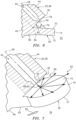
- the splash plate 26 is configured to redirect (e.g., disperse) the fuel injected into the fluid passage 34 from the fuel nozzle 25 into a disperse (e.g., a widespread) pattern (e.g., see FIGS. 7 and 8 ).
- the splash plate 26, for example, is arranged proximate and laterally overlaps the nozzle orifice 50.
- the splash plate 26 is longitudinally spaced from the fuel nozzle 25 and its nozzle orifice 50 by a longitudinal distance 64 along the longitudinal centerline 48. This longitudinal distance 64 may be equal to or different (e.g., greater or less) than a width (e.g., diameter) of the nozzle passage 40.
- the present disclosure is not limited to the foregoing exemplary dimensional relationship between the splash plate 26 and the fuel nozzle 25.
- the splash plate 26 of FIGS. 4 and 5 is configured with a (e.g., circular) puck-like body.
- the splash plate 26 of FIG. 4 extends axially along a centerline axis 68 of the splash plate 26 between a frontside splash plate surface 70 and a backside splash plate surface 72, which backside splash plate surface 72 is axially opposite the frontside splash plate surface 70.
- Each of these splash plate surfaces 70 and 72 may have a generally circular shape. However, in other configurations, one or more of the splash plate surfaces 70 and 72 may each have a non-circular (e.g., oval, polygonal, etc.) shape.
- Each of the splash plate surfaces 70 and 72 may be configured as a smooth and/or planar surface.
- one or more of the splash plate surfaces 70 and 72 may each be configured as a non-planar (e.g., concave, convex, etc.) surface and/or with one or more flow disruptions; e.g., apertures or projections.
- the splash plate 26 of FIGS. 4 and 5 also includes at least one side perimeter surface 74 that extends axially between the opposing splash plate surfaces 70 and 72 and circumferentially about the centerline axis 68 of the splash plate 26.
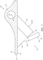
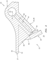
- the splash plate 26 and, more particularly, its frontside splash plate surface 70 is angularly offset from the longitudinal centerline 48 and/or fuel trajectory 90 (discussed below) by a first acute angle 76 (an angle that is greater than zero degrees and less than ninety degrees) when viewed, for example, in the plane of FIG. 4 ; e.g., a plane that laterally bisects one or more or each of the components 26, 44 and 46 and/or is parallel with and coincident with the centerline 48.
- the first acute angle 76 may be between sixty degrees (60°) and eighty degrees (80°) as shown in FIG.
- the first acute angle 76 may be substantially (e.g., +/- 2°) or exactly equal to seventy degrees (70°).
- the first acute angle 76 may be between thirty-five degrees (35°) and fifty-five degrees (55°) as shown in FIG. 6 ; e.g., the first acute angle 76 may be substantially (e.g., +/- 2°) or exactly equal to forty-five degrees (45°).
- the splash plate 26 of FIG. 4 and, more particularly, its frontside splash plate surface 70 is angularly offset from a plane of the nozzle orifice 50 and/or a surface 78 of the nozzle tube 44 at the fuel nozzle distal end 36 by a second acute angle 80.
- the second acute angle 80 may be between ten degrees (10°) and thirty degrees (30°) as shown in FIG. 4 ; e.g., the second acute angle 80 may be substantially (e.g., +/- 2°) or exactly equal to twenty degrees (20°). In another example, the second acute angle 80 may be between thirty-five degrees (35°) and fifty-five degrees (55°) as shown in FIG. 6 ; e.g., the second acute angle 80 may be substantially (e.g., +/- 2°) or exactly equal to forty-five degrees (45°).
- the splash plate 26 of FIGS. 4 and 5 is connected to the fuel nozzle 25 by at least one support member 82.
- the support member 82 may be configured as a beam and/or a pylon.
- the support member 82 of FIGS. 4 and 5 for example, has an elongated body that is connected to and extends between the fuel nozzle 25 and the splash plate 26. More particularly, the support member 82 of FIGS. 4 and 5 is connected (e.g., directly) to and extends between the nozzle support structure 46 and the splash plate 26. Of course, in other configurations, the support member 82 may also or alternatively be connected to and/or project out from the nozzle tube 44.
- the support member 82 of FIG. 4 is arranged at (e.g., on, adjacent or proximate) an upstream end 84 of the splash plate 26 relative to a fluid flow 85 (e.g., an air flow) within the fluid passage 34 (e.g., an air passage).
- the support member 82 may thereby be arranged upstream of the nozzle orifice 50 relative to the fluid flow 85 within the fluid passage 34.
- the fuel redirected (e.g., dispersed) by the splash plate 26 may flow unobstructed in a downstream direction through a spatial gap 86 between the splash plate 26 and the fuel nozzle 25.
- the present disclosure is not limited to such an exemplary support member placement.
- fuel is directed into the supply passage 32 from a fuel source (not shown). At least a portion (or all) of the fuel within the supply passage 32 is directed into the nozzle passage 40. Referring to FIG. 7 , this fuel flows through the nozzle passage 40 and out of the fuel nozzle 25 through the nozzle orifice 50 and into the fluid passage 34 (more particularly, into the spatial gap 86) as a fuel jet 88 along a fuel jet trajectory 90, which may be parallel (e.g., coaxial) with the centerline 48.
- This fuel jet 88 may be a linear concentrated flow / stream of fuel versus, for example, a spread-out pattern of fuel such as a conical film of fuel.
- the fuel jet 88 flows through the spatial gap 86 along its trajectory 90 and impacts (e.g., impinges against) the frontside splash plate surface 70 at a target area; e.g., an impingement area.
- a target area e.g., an impingement area.
- the splash plate 26 redirects (e.g., disperses) the impinging fuel jet 88 radially outward (relative to the fuel jet trajectory 90) into a (e.g., uniform and/or symmetrical) disperse radiant pattern 92 (e.g., an arcuate and/or a generally planar film; schematically shown in FIGS. 7 and 8 via discrete flow arrows).
- a disperse radiant pattern 92 e.g., an arcuate and/or a generally planar film; schematically shown in FIGS. 7 and 8 via discrete flow arrows.
- the fuel may thereby be more evenly dispersed / spread / mixed into the fluid (e.g., air) flowing past the fuel nozzle 25 and the splash plate 26 within the fluid passage 34. Providing such relatively even mixing of the fuel and the fluid may in turn increase fuel burn efficiency and/or reduce likelihood of carbon formation within the turbine engine.
- the fluid e.g., air
- the splash plate 26 is cantilevered from the fuel nozzle 25 through the support member 82.
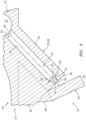
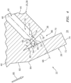
- the splash plate 26 is further supported by at least one additional support member 82B as shown, for example, in FIGS. 9 and 10 .
- This downstream support member 82B is connected to and extends between the fuel nozzle 25 and the splash plate 26. More particularly, the downstream support member 82B of FIG. 9 is connected to and projects out from the nozzle tube 44.
- the downstream support member 82B of FIG. 10 is connected to and projects out from another (e.g., downstream) nozzle support structure 46B (e.g., web) for the fuel nozzle 25.
- the downstream support member 82B may be positioned opposite to (e.g., diametrically opposed with) the upstream support member 82; however, the present disclosure is not limited to such exemplary support member locations.
- including more than one support member may also provide for reducing the size of the support member (e.g., 82, 82B) e.g., thickness. Reducing the size of the support member(s) (e.g., 82, 82B) may in turn reduce flow impedance to the dispersed fuel traveling past the support members (e.g., 82, 82B) and, thus, promote further mixing between the fuel and the fluid flow; e.g., air flow.
- the fuel nozzle 25 may be one of a plurality of fuel nozzles 25 connected to the apparatus base 27 and fluidly coupled with the fuel conduit 24. These fuel nozzles 25 may be arranged circumferentially about a centerline / rotational axis 94 of the turbine engine in an annular array. Each of the fuel nozzles 25 may be associated with a respective splash plate 26.
- the apparatus base 27, the fuel conduit 24 and each fuel nozzle 25 may be configured together in an integral, monolithic body.
- Each fuel nozzle 25 and its respective splash plate 26 may also or alternatively be configured together in the monolithic body.
- selecting the first acute angle 76 of FIG. 4 to be between sixty degrees and eighty degrees (e.g., approximately or exactly seventy degrees) and/or the second acute angle 80 to be between ten degrees and thirty degrees (e.g., approximately or exactly twenty degrees) may facilitate additive manufacturing of the turbine engine apparatus 20 as a monolithic body.
- the present disclosure is not limited to such an exemplary construction.
- one or more or each of the apparatus components and/or portions thereof may be individually formed and subsequently connected (e.g., fastener and/or bonded) together.
- the turbine engine apparatus 20 may also include one or more fuel vaporizers 96.
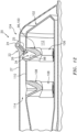
- Each fuel nozzle 25 is arranged with a respective one of the fuel vaporizers 96. More particularly, each fuel nozzle 25 projects into a respective one of the fuel vaporizers 96 and the associated splash plate 26 is arranged within a fluid passage (e.g., an air passage) of the respective fuel vaporizer 96. With such an arrangement, each splash plate 26 may direct a portion of the dispersed fuel to impinge against a surface 98 of the respective fuel vaporizer 96.
- the fuel vaporizer 96 may provide initial or further vaporization of the dispersed fuel.
- Each splash plate 26 may also direct another portion of the dispersed fuel to mix with the passing fluid (e.g., air) without impinging against the fuel vaporizer 96.
- the ratio of an amount of the dispersed fuel which contacts the fuel vaporizer 96 versus an amount of the dispersed fuel which does not contact the fuel vaporizer 96 may be controlled by adjusting a value of the first acute angle 76 of FIGS. 4 and 6 .
- a value of the first acute angle 76 of FIGS. 4 and 6 For example, when the value of the first acute angle 76 is increased towards ninety degrees (e.g., see FIG. 4 ), more of the fuel dispersed by the splash plate 26 may penetrate further into the fluid flow and, thus, more of the dispersed fuel may contact the fuel vaporizer 96 (see FIG. 12 ).
- the value of the first acute angle 76 is decreased towards zero degrees (e.g., see FIG. 6 )
- less of the fuel dispersed by the splash plate 26 may penetrate far into the fluid flow and, thus, less of the dispersed fuel may contact the fuel vaporizer 96 (see FIG. 12 ).
- each fuel vaporizer 96 is configured as a structure such as a flow tube 100 (e.g., a fluid tube, an air tube) for a combustor 102 in the combustor section 104.
- the combustor 102 may also include at least one flow tube 106 in between, for example, each circumferentially neighboring set of the vaporizers 96 and/or one or more flow tubes 108 in another (e.g., forward / upstream) array.
- Each of the flow tubes 100, 106, 108 is connected to and projects out from a wall 110 of the combustor 102 and into a combustion chamber 112 at least partially defined by the combustor wall 110.
- the fluid passage 34 (e.g., air passage) of each flow tube 100 is configured to receive fluid and, more particularly, compressed air from a compressor section of the turbine engine (not visible in FIGS. 11 and 12 ) through another plenum 114. This compressed air is directed through the respective fluid passage 34 and into the combustion chamber 112. However, before reaching the combustion chamber 112, the air within the respective fluid passage 34 is mixed with fuel dispersed from a respective one of the splash plates 26 to provide a mixture of compressed air and atomized fuel.
- the fuel By dispersing the fuel within the flow tube 100, the fuel may be more likely to atomize within the respective fluid passage 34; e.g., upon dispersing into the airflow and/or upon impinging against the surface 98 (e.g., an inner side wall surface of the flow tube 100).
- the fuel injector assembly 22 may reduce the likelihood of carbon buildup within the fluid passage 34 and/or within the combustion chamber 112.
- each fuel vaporizer 96 / flow tube 100 is configured to direct an axial fluid flow therewith / therethrough.
- the term axial fluid flow may describe a straight or linear flow of fluid such as a non-swirled fluid flow; e.g., non-swirled air.
- none of the fuel vaporizers 96 / flow tubes 100 is configured with or otherwise receives its fluid (e.g., air) directly and/or indirectly from a swirler.
- the fluid flowing through each fuel vaporizer 96 / flow tube 100 is non-swirled; e.g., the fluid primarily (or only) has axial velocity / momentum components with little or no tangential velocity / momentum components.
- each fuel vaporizer 96 / flow tube 100 may include relatively low level flow disruptions, turbulence, vortices, etc. caused when, for example, the fluid turns from the plenum 114 into the fluid passage 34, etc.
- FIG. 13 illustrates one such type and configuration of the turbine engine - a single spool, radial-flow turbojet turbine engine 116 configured for propelling an unmanned aerial vehicle (UAV), a drone, or any other manned or unmanned aircraft or self-propelled projectile.
- the turbine engine 116 includes an upstream inlet 118, a (e.g., radial) compressor section 120, the combustor section 104, a (e.g., radial) turbine section 122 and a downstream exhaust 124 fluidly coupled in series.
- a compressor rotor 126 in the compressor section 120 is coupled with a turbine rotor 128 in the turbine section 122 by a shaft 130, which rotates about the centerline / rotational axis 94 of the turbine engine 116.
- the turbine engine apparatus 20 may be included in various turbine engines other than the one described above.
- the turbine engine apparatus 20, for example, may be included in a geared turbine engine where a gear train connects one or more shafts to one or more rotors in a fan section, a compressor section and/or any other engine section.
- the turbine engine apparatus 20 may be included in a turbine engine configured without a gear train.
- the turbine engine apparatus 20 may be included in a geared or non-geared turbine engine configured with a single spool (e.g., see FIG. 13 ), with two spools, or with more than two spools.
- the turbine engine may be configured as a turbofan engine, a turbojet engine, a propfan engine, a pusher fan engine or any other type of turbine engine.
- the present disclosure therefore is not limited to any particular types or configurations of turbine engines.
- the present disclosure is also not limited to a propulsion system application.
- the gas turbine engine may alternatively be configured as an auxiliary power unit (APU) or an industrial gas turbine engine.
- APU auxiliary power unit
Landscapes
- Engineering & Computer Science (AREA)
- Chemical & Material Sciences (AREA)
- Combustion & Propulsion (AREA)
- Mechanical Engineering (AREA)
- General Engineering & Computer Science (AREA)
- Fuel-Injection Apparatus (AREA)
- Nozzles For Spraying Of Liquid Fuel (AREA)
- Spray-Type Burners (AREA)
Claims (12)
- Vorrichtung (20) für einen Turbinenmotor (116), umfassend einen monolithischen Körper, der eine Prallplatte (26) und eine Brennstoffdüse (25) beinhaltet, wobei:die Prallplatte (26) eine Prallplattenoberfläche (70) beinhaltet;die Brennstoffdüse (25) eine Düsenöffnung (50) beinhaltet;die Brennstoffdüse (25) dazu konfiguriert ist, Brennstoff so aus der Düsenöffnung (50) zu leiten, dass er auf die Prallplattenoberfläche (70) trifft; unddie Vorrichtung (20) ferner ein Trägerelement (82) umfasst, das die Prallplatte (26) mit der Brennstoffdüse (25) verbindet und sich zwischen ihnen erstreckt,dadurch gekennzeichnet, dassdie Vorrichtung (20) ferner ein zweites Trägerelement (82B) umfasst, das die Prallplatte (26) mit der Brennstoffdüse (25) verbindet und sich zwischen ihnen erstreckt.
- Vorrichtung (20) nach Anspruch 1, wobei:die Brennstoffdüse (25) dazu konfiguriert ist, den Brennstoff als einen Brennstoffstrahl (88) aus der Düsenöffnung (50) zu leiten; unddie Prallplatte (26) dazu konfiguriert ist, den Brennstoffstrahl (88) in ein strahlendes Brennstoffmuster (92) umzulenken.
- Vorrichtung (20) nach Anspruch 1 oder 2, wobei die Prallplatte (26) von der Düsenöffnung (50) beabstandet ist und diese überlappt.
- Vorrichtung (20) nach einem der vorhergehenden Ansprüche, wobei die Prallplattenoberfläche (70) eine ebene Prallplattenoberfläche (70) umfasst.
- Vorrichtung (20) nach einem der vorhergehenden Ansprüche, wobei
die Brennstoffdüse (25) dazu konfiguriert ist, den Brennstoff so entlang einer Trajektorie (90) aus der Düsenöffnung (50) zu leiten, dass er auf die Prallplattenoberfläche (70) trifft; und die Prallplattenoberfläche (70) um einen spitzen Winkel (76) von der Trajektorie (90) winkelversetzt ist. - Vorrichtung (20) nach Anspruch 5, wobei der spitze Winkel (76) zwischen sechzig Grad und achtzig Grad beträgt.
- Vorrichtung nach Anspruch 5, wobei der spitze Winkel (76) zwischen fünfunddreißig Grad und fünfundfünfzig Grad beträgt.
- Vorrichtung (20) nach einem der vorhergehenden Ansprüche, wobei:die Brennstoffdüse (25) in einen Strömungskanal (34) vorspringt; unddas Trägerelement (82) relativ zu einem Fluidstrom (85) innerhalb des Strömungskanals (34) stromaufwärts der Düsenöffnung (50) angeordnet ist.
- Vorrichtung (20) nach einem der vorhergehenden Ansprüche, wobei:die Brennstoffdüse (25) ein Düsenrohr (44) beinhaltet, das eine Längsmittellinie (48) aufweist und sich entlang dieser erstreckt; unddie Düsenöffnung (50) koaxial zu der Längsmittellinie (48) ist.
- Vorrichtung (20) nach einem der vorhergehenden Ansprüche, ferner umfassend einen Brennstoffverdampfer (96), wobei die Prallplatte (26) dazu konfiguriert ist, mindestens einen Teil des verteilten Brennstoffs gegen den Brennstoffverdampfer (96) zu leiten.
- Vorrichtung (20) nach einem der vorhergehenden Ansprüche, ferner umfassend ein Luftrohr (100), das einen Luftkanal umfasst, wobei:die Brennstoffdüse (25) in den Luftkanal (34) vorspringt; unddie Prallplatte (26) derart innerhalb des Luftkanals (34) angeordnet ist, dass die Prallplatte (26) dazu konfiguriert ist, mindestens einen Teil des verteilten Brennstoffs gegen eine innere Seitenwandoberfläche (98) des Luftrohrs (100) zu leiten.
- Vorrichtung (20) nach Anspruch 11, wobei die Vorrichtung (20) ferner eine Brennkammerwand (110) umfasst, die mindestens teilweise eine Verbrennungskammer (112) bildet, und wobei das Luftrohr (100) mit der Brennkammerwand (110) verbunden ist und in die Verbrennungskammer (112) vorspringt.
Applications Claiming Priority (1)
| Application Number | Priority Date | Filing Date | Title |
|---|---|---|---|
| US17/108,606 US11649964B2 (en) | 2020-12-01 | 2020-12-01 | Fuel injector assembly for a turbine engine |
Publications (2)
| Publication Number | Publication Date |
|---|---|
| EP4008959A1 EP4008959A1 (de) | 2022-06-08 |
| EP4008959B1 true EP4008959B1 (de) | 2024-01-31 |
Family
ID=78820367
Family Applications (1)
| Application Number | Title | Priority Date | Filing Date |
|---|---|---|---|
| EP21211805.3A Active EP4008959B1 (de) | 2020-12-01 | 2021-12-01 | Vorrichtung fur einen turbinenmotor umfassend eine brennstoffprallplate |
Country Status (2)
| Country | Link |
|---|---|
| US (2) | US11649964B2 (de) |
| EP (1) | EP4008959B1 (de) |
Cited By (1)
| Publication number | Priority date | Publication date | Assignee | Title |
|---|---|---|---|---|
| US12116934B2 (en) | 2023-02-10 | 2024-10-15 | Rtx Corporation | Turbine engine fuel injector with oxygen circuit |
Families Citing this family (9)
| Publication number | Priority date | Publication date | Assignee | Title |
|---|---|---|---|---|
| US12584632B2 (en) * | 2023-10-27 | 2026-03-24 | Rtx Corporation | Modular injector bolt for an engine |
| US12535214B2 (en) | 2024-04-19 | 2026-01-27 | Rtx Corporation | Attaching powerplant structures together using fuel injector bolts |
| US20250334269A1 (en) * | 2024-04-26 | 2025-10-30 | Rtx Corporation | Sieve rde injector with variable pressure drop capability |
| WO2026010683A2 (en) * | 2024-05-20 | 2026-01-08 | Silverlining Inc. | Aerosol technology |
| US20260085836A1 (en) * | 2024-09-20 | 2026-03-26 | Rtx Corporation | Flow Assisted Integral Splash Plate |
| US12529337B1 (en) | 2024-11-18 | 2026-01-20 | Rtx Corporation | Additively manufactured turbine engine case with fuel manifold |
| US12455078B1 (en) | 2025-03-14 | 2025-10-28 | Rtx Corporation | Unitary case integrated flow scoops |
| US12516816B1 (en) | 2025-03-14 | 2026-01-06 | Rtx Corporation | 3D diffuser fed scoop fuel injector |
| US12693016B1 (en) * | 2025-05-20 | 2026-07-28 | Rtx Corporation | Mesh based fuel flow guide |
Family Cites Families (67)
| Publication number | Priority date | Publication date | Assignee | Title |
|---|---|---|---|---|
| US1460470A (en) | 1922-05-22 | 1923-07-03 | Askins Joseph | Vaporizer and mixer for internal-combustion engines |
| US2385833A (en) | 1943-01-27 | 1945-10-02 | Kevork K Nahigyan | Fuel vaporizer for jet propulsion units |
| US2616258A (en) | 1946-01-09 | 1952-11-04 | Bendix Aviat Corp | Jet engine combustion apparatus, including pilot burner for ignition and vaporization of main fuel supply |
| US2727358A (en) | 1952-03-27 | 1955-12-20 | A V Roe Canada Ltd | Reverse-flow vaporizer with single inlet and plural outlets |
| US3153323A (en) | 1954-03-31 | 1964-10-20 | James R Hamm | Internal combustion apparatus |
| US3053461A (en) | 1959-11-12 | 1962-09-11 | Bruce D Inglis | Pressure controlled spray device |
| GB1136543A (en) | 1966-02-21 | 1968-12-11 | Rolls Royce | Liquid fuel combustion apparatus for gas turbine engines |
| US3603711A (en) | 1969-09-17 | 1971-09-07 | Edgar S Downs | Combination pressure atomizer and surface-type burner for liquid fuel |
| DE2038643A1 (de) | 1970-08-04 | 1972-02-10 | Bosch Gmbh Robert | Kraftstoffeinspritzduese |
| US3912164A (en) * | 1971-01-11 | 1975-10-14 | Parker Hannifin Corp | Method of liquid fuel injection, and to air blast atomizers |
| US3693354A (en) | 1971-01-22 | 1972-09-26 | Gen Electric | Aircraft engine fan duct burner system |
| US3777983A (en) | 1971-12-16 | 1973-12-11 | Gen Electric | Gas cooled dual fuel air atomized fuel nozzle |
| JPS5342897B2 (de) | 1972-11-09 | 1978-11-15 | ||
| DE2326680C3 (de) | 1973-05-25 | 1980-09-25 | Mtu Motoren- Und Turbinen-Union Muenchen Gmbh, 8000 Muenchen | Flammrohr mit Vormischkammer für Brennkammern von Gasturbinentriebwerken |
| US4081958A (en) | 1973-11-01 | 1978-04-04 | The Garrett Corporation | Low nitric oxide emission combustion system for gas turbines |
| US3915137A (en) | 1974-03-04 | 1975-10-28 | Hugh K Evans | Fuel vaporizer |
| GB1481617A (en) | 1974-10-07 | 1977-08-03 | Rolls Royce | Gas turbine fuel burners |
| US4134260A (en) | 1977-10-25 | 1979-01-16 | General Motors Corporation | Afterburner flow mixing means in turbofan jet engine |
| US4242863A (en) | 1978-03-16 | 1981-01-06 | Caterpillar Tractor Co. | Dual phase fuel vaporizing combustor |
| DE2836534C2 (de) | 1978-08-21 | 1982-09-02 | Oertli AG Dübendorf, Dübendorf | Verfahren zum Verbrennen flüssigen Brennstoffes und Brenner zur Durchführung des Verfahrens |
| GB2036296B (en) | 1978-11-20 | 1982-12-01 | Rolls Royce | Gas turbine |
| US4967562A (en) * | 1988-12-12 | 1990-11-06 | Sundstrand Corporation | Turbine engine with high efficiency fuel atomization |
| US4989404A (en) * | 1988-12-12 | 1991-02-05 | Sundstrand Corporation | Turbine engine with high efficiency fuel atomization |
| US5140807A (en) * | 1988-12-12 | 1992-08-25 | Sundstrand Corporation | Air blast tube impingement fuel injector for a gas turbine engine |
| IL93630A0 (en) | 1989-03-27 | 1990-12-23 | Gen Electric | Flameholder for gas turbine engine afterburner |
| US5063745A (en) * | 1989-07-13 | 1991-11-12 | Sundstrand Corporation | Turbine engine with pin injector |
| US5241818A (en) * | 1989-07-13 | 1993-09-07 | Sundstrand Corporation | Fuel injector for a gas turbine engine |
| GB2236588B (en) | 1989-08-31 | 1993-08-18 | Rolls Royce Plc | Improved fuel vapouriser |
| US5263316A (en) * | 1989-12-21 | 1993-11-23 | Sundstrand Corporation | Turbine engine with airblast injection |
| US5277022A (en) * | 1990-06-22 | 1994-01-11 | Sundstrand Corporation | Air blast fuel injecton system |
| US5167122A (en) * | 1991-04-30 | 1992-12-01 | Sundstrand Corporation | Fuel system for a turbo machine |
| US5321951A (en) | 1992-03-30 | 1994-06-21 | General Electric Company | Integral combustor splash plate and sleeve |
| US5423178A (en) | 1992-09-28 | 1995-06-13 | Parker-Hannifin Corporation | Multiple passage cooling circuit method and device for gas turbine engine fuel nozzle |
| FR2721693B1 (fr) | 1994-06-22 | 1996-07-19 | Snecma | Procédé et dispositif pour alimenter en carburant et refroidir l'injecteur de décollage d'une chambre de combustion à deux têtes. |
| US5836163A (en) | 1996-11-13 | 1998-11-17 | Solar Turbines Incorporated | Liquid pilot fuel injection method and apparatus for a gas turbine engine dual fuel injector |
| US5873237A (en) | 1997-01-24 | 1999-02-23 | Westinghouse Electric Corporation | Atomizing dual fuel nozzle for a combustion turbine |
| DE69916911T2 (de) | 1998-02-10 | 2005-04-21 | Gen Electric | Brenner mit gleichmässiger Brennstoff/Luft Vormischung zur emissionsarmen Verbrennung |
| US6925809B2 (en) | 1999-02-26 | 2005-08-09 | R. Jan Mowill | Gas turbine engine fuel/air premixers with variable geometry exit and method for controlling exit velocities |
| US6321541B1 (en) | 1999-04-01 | 2001-11-27 | Parker-Hannifin Corporation | Multi-circuit multi-injection point atomizer |
| US6460344B1 (en) | 1999-05-07 | 2002-10-08 | Parker-Hannifin Corporation | Fuel atomization method for turbine combustion engines having aerodynamic turning vanes |
| DE19948674B4 (de) | 1999-10-08 | 2012-04-12 | Alstom | Verbrennungseinrichtung, insbesondere für den Antrieb von Gasturbinen |
| US6931862B2 (en) | 2003-04-30 | 2005-08-23 | Hamilton Sundstrand Corporation | Combustor system for an expendable gas turbine engine |
| US6986253B2 (en) | 2003-07-16 | 2006-01-17 | General Electric Company | Methods and apparatus for cooling gas turbine engine combustors |
| JP4653985B2 (ja) | 2004-09-02 | 2011-03-16 | 株式会社日立製作所 | 燃焼器とガスタービン燃焼器、及び空気を燃焼器に供給する方法 |
| US7437876B2 (en) | 2005-03-25 | 2008-10-21 | General Electric Company | Augmenter swirler pilot |
| US7578131B2 (en) | 2005-06-30 | 2009-08-25 | United Technologies Corporation | Augmentor spray bar mounting |
| US7225623B2 (en) | 2005-08-23 | 2007-06-05 | General Electric Company | Trapped vortex cavity afterburner |
| US20070119572A1 (en) | 2005-11-30 | 2007-05-31 | Raytheon Company | System and Method for Boiling Heat Transfer Using Self-Induced Coolant Transport and Impingements |
| WO2008097320A2 (en) | 2006-06-01 | 2008-08-14 | Virginia Tech Intellectual Properties, Inc. | Premixing injector for gas turbine engines |
| US7777155B2 (en) | 2007-02-21 | 2010-08-17 | United Technologies Corporation | System and method for an integrated additive manufacturing cell for complex components |
| US7954328B2 (en) | 2008-01-14 | 2011-06-07 | United Technologies Corporation | Flame holder for minimizing combustor screech |
| US9188341B2 (en) | 2008-04-11 | 2015-11-17 | General Electric Company | Fuel nozzle |
| FR2932251B1 (fr) * | 2008-06-10 | 2011-09-16 | Snecma | Chambre de combustion de moteur a turbine a gaz comportant des deflecteurs en cmc |
| EP2161500A1 (de) | 2008-09-04 | 2010-03-10 | Siemens Aktiengesellschaft | Verbrennungssystem und Verfahren zur Verringerung der Verbrennungsinstabilität und/oder Emissionen eines Verbrennungssystems |
| US8607570B2 (en) | 2009-05-06 | 2013-12-17 | General Electric Company | Airblown syngas fuel nozzle with diluent openings |
| US8752386B2 (en) | 2010-05-25 | 2014-06-17 | Siemens Energy, Inc. | Air/fuel supply system for use in a gas turbine engine |
| US8769955B2 (en) | 2010-06-02 | 2014-07-08 | Siemens Energy, Inc. | Self-regulating fuel staging port for turbine combustor |
| US8955329B2 (en) | 2011-10-21 | 2015-02-17 | General Electric Company | Diffusion nozzles for low-oxygen fuel nozzle assembly and method |
| US9062609B2 (en) | 2012-01-09 | 2015-06-23 | Hamilton Sundstrand Corporation | Symmetric fuel injection for turbine combustor |
| US10619855B2 (en) | 2012-09-06 | 2020-04-14 | United Technologies Corporation | Fuel delivery system with a cavity coupled fuel injector |
| US9803498B2 (en) | 2012-10-17 | 2017-10-31 | United Technologies Corporation | One-piece fuel nozzle for a thrust engine |
| EP3033508B1 (de) | 2013-08-16 | 2018-06-20 | United Technologies Corporation | Gekühltes kraftstoffeinspritzsystem für einen gasturbinenmotor |
| EP3055620A4 (de) | 2013-10-07 | 2017-01-18 | United Technologies Corporation | Brennstoffverdampfer für eine turbinenmotorbrennkammer |
| US10139108B2 (en) | 2015-06-08 | 2018-11-27 | Siemens Energy, Inc. | D5/D5A DF-42 integrated exit cone and splash plate |
| US10570865B2 (en) | 2016-11-08 | 2020-02-25 | Ford Global Technologies, Llc | Fuel injector with variable flow direction |
| US11156156B2 (en) | 2018-10-04 | 2021-10-26 | Raytheon Technologies Corporation | Gas turbine engine with a unitary structure and method for manufacturing the same |
| US11136901B2 (en) * | 2019-05-17 | 2021-10-05 | Raytheon Technologies Corporation | Monolithic combustor for attritiable engine applications |
-
2020
- 2020-12-01 US US17/108,606 patent/US11649964B2/en active Active
-
2021
- 2021-12-01 EP EP21211805.3A patent/EP4008959B1/de active Active
-
2023
- 2023-05-15 US US18/197,299 patent/US12422142B2/en active Active
Cited By (1)
| Publication number | Priority date | Publication date | Assignee | Title |
|---|---|---|---|---|
| US12116934B2 (en) | 2023-02-10 | 2024-10-15 | Rtx Corporation | Turbine engine fuel injector with oxygen circuit |
Also Published As
| Publication number | Publication date |
|---|---|
| EP4008959A1 (de) | 2022-06-08 |
| US12422142B2 (en) | 2025-09-23 |
| US20240044495A1 (en) | 2024-02-08 |
| US11649964B2 (en) | 2023-05-16 |
| US20220170636A1 (en) | 2022-06-02 |
Similar Documents
| Publication | Publication Date | Title |
|---|---|---|
| US12422142B2 (en) | Fuel injector assembly for a turbine engine | |
| US8387391B2 (en) | Aerodynamically enhanced fuel nozzle | |
| US8726668B2 (en) | Fuel atomization dual orifice fuel nozzle | |
| US20120151928A1 (en) | Cooling flowpath dirt deflector in fuel nozzle | |
| EP3137814B1 (de) | Brennkammerbrenneranordnung | |
| US10883719B2 (en) | Prefilming fuel/air mixer | |
| EP4202302B1 (de) | Brennstoffdüse und verwirbler | |
| JPH07217451A (ja) | 燃料噴射装置 | |
| US11421883B2 (en) | Fuel injector assembly with a helical swirler passage for a turbine engine | |
| US11906165B2 (en) | Gas turbine nozzle having an inner air swirler passage and plural exterior fuel passages | |
| US10914237B2 (en) | Airblast injector for a gas turbine engine | |
| EP4414608A2 (de) | Brennstoffeinspritzventil für turbinenmotor mit sauerstoffkreislauf | |
| EP3078913A1 (de) | Brennkammerbrenneranordnung | |
| US10352570B2 (en) | Turbine engine fuel injection system and methods of assembling the same | |
| US11754287B2 (en) | Fuel injector assembly for a turbine engine | |
| EP3348906B1 (de) | Gasturbinenkraftstoffeinspritzer | |
| US9581334B2 (en) | Annular combustion chamber in a turbine engine | |
| US20210285640A1 (en) | Nozzle with jet generator channel for fuel to be injected into a combustion chamber of an engine | |
| US12546469B1 (en) | Gas turbine engine fuel injector with multiple fuel circuits | |
| CN114258473A (zh) | 包括辅助喷射系统的燃烧室,以及燃料供应方法 | |
| US20180195727A1 (en) | Fuel injector |
Legal Events
| Date | Code | Title | Description |
|---|---|---|---|
| PUAI | Public reference made under article 153(3) epc to a published international application that has entered the european phase |
Free format text: ORIGINAL CODE: 0009012 |
|
| STAA | Information on the status of an ep patent application or granted ep patent |
Free format text: STATUS: THE APPLICATION HAS BEEN PUBLISHED |
|
| AK | Designated contracting states |
Kind code of ref document: A1 Designated state(s): AL AT BE BG CH CY CZ DE DK EE ES FI FR GB GR HR HU IE IS IT LI LT LU LV MC MK MT NL NO PL PT RO RS SE SI SK SM TR |
|
| STAA | Information on the status of an ep patent application or granted ep patent |
Free format text: STATUS: REQUEST FOR EXAMINATION WAS MADE |
|
| 17P | Request for examination filed |
Effective date: 20221207 |
|
| RBV | Designated contracting states (corrected) |
Designated state(s): AL AT BE BG CH CY CZ DE DK EE ES FI FR GB GR HR HU IE IS IT LI LT LU LV MC MK MT NL NO PL PT RO RS SE SI SK SM TR |
|
| GRAP | Despatch of communication of intention to grant a patent |
Free format text: ORIGINAL CODE: EPIDOSNIGR1 |
|
| STAA | Information on the status of an ep patent application or granted ep patent |
Free format text: STATUS: GRANT OF PATENT IS INTENDED |
|
| RIC1 | Information provided on ipc code assigned before grant |
Ipc: F23R 3/32 20060101ALI20230724BHEP Ipc: F23R 3/28 20060101AFI20230724BHEP |
|
| INTG | Intention to grant announced |
Effective date: 20230807 |
|
| RAP3 | Party data changed (applicant data changed or rights of an application transferred) |
Owner name: RTX CORPORATION |
|
| GRAS | Grant fee paid |
Free format text: ORIGINAL CODE: EPIDOSNIGR3 |
|
| GRAA | (expected) grant |
Free format text: ORIGINAL CODE: 0009210 |
|
| STAA | Information on the status of an ep patent application or granted ep patent |
Free format text: STATUS: THE PATENT HAS BEEN GRANTED |
|
| AK | Designated contracting states |
Kind code of ref document: B1 Designated state(s): AL AT BE BG CH CY CZ DE DK EE ES FI FR GB GR HR HU IE IS IT LI LT LU LV MC MK MT NL NO PL PT RO RS SE SI SK SM TR |
|
| REG | Reference to a national code |
Ref country code: GB Ref legal event code: FG4D Ref country code: CH Ref legal event code: EP |
|
| REG | Reference to a national code |
Ref country code: DE Ref legal event code: R096 Ref document number: 602021008947 Country of ref document: DE |
|
| REG | Reference to a national code |
Ref country code: IE Ref legal event code: FG4D |
|
| REG | Reference to a national code |
Ref country code: LT Ref legal event code: MG9D |
|
| REG | Reference to a national code |
Ref country code: NL Ref legal event code: MP Effective date: 20240131 |
|
| PG25 | Lapsed in a contracting state [announced via postgrant information from national office to epo] |
Ref country code: IS Free format text: LAPSE BECAUSE OF FAILURE TO SUBMIT A TRANSLATION OF THE DESCRIPTION OR TO PAY THE FEE WITHIN THE PRESCRIBED TIME-LIMIT Effective date: 20240531 |
|
| PG25 | Lapsed in a contracting state [announced via postgrant information from national office to epo] |
Ref country code: LT Free format text: LAPSE BECAUSE OF FAILURE TO SUBMIT A TRANSLATION OF THE DESCRIPTION OR TO PAY THE FEE WITHIN THE PRESCRIBED TIME-LIMIT Effective date: 20240131 |
|
| PG25 | Lapsed in a contracting state [announced via postgrant information from national office to epo] |
Ref country code: GR Free format text: LAPSE BECAUSE OF FAILURE TO SUBMIT A TRANSLATION OF THE DESCRIPTION OR TO PAY THE FEE WITHIN THE PRESCRIBED TIME-LIMIT Effective date: 20240501 |
|
| REG | Reference to a national code |
Ref country code: AT Ref legal event code: MK05 Ref document number: 1654119 Country of ref document: AT Kind code of ref document: T Effective date: 20240131 |
|
| PG25 | Lapsed in a contracting state [announced via postgrant information from national office to epo] |
Ref country code: HR Free format text: LAPSE BECAUSE OF FAILURE TO SUBMIT A TRANSLATION OF THE DESCRIPTION OR TO PAY THE FEE WITHIN THE PRESCRIBED TIME-LIMIT Effective date: 20240131 Ref country code: NL Free format text: LAPSE BECAUSE OF FAILURE TO SUBMIT A TRANSLATION OF THE DESCRIPTION OR TO PAY THE FEE WITHIN THE PRESCRIBED TIME-LIMIT Effective date: 20240131 Ref country code: RS Free format text: LAPSE BECAUSE OF FAILURE TO SUBMIT A TRANSLATION OF THE DESCRIPTION OR TO PAY THE FEE WITHIN THE PRESCRIBED TIME-LIMIT Effective date: 20240430 |
|
| PG25 | Lapsed in a contracting state [announced via postgrant information from national office to epo] |
Ref country code: ES Free format text: LAPSE BECAUSE OF FAILURE TO SUBMIT A TRANSLATION OF THE DESCRIPTION OR TO PAY THE FEE WITHIN THE PRESCRIBED TIME-LIMIT Effective date: 20240131 |
|
| PG25 | Lapsed in a contracting state [announced via postgrant information from national office to epo] |
Ref country code: AT Free format text: LAPSE BECAUSE OF FAILURE TO SUBMIT A TRANSLATION OF THE DESCRIPTION OR TO PAY THE FEE WITHIN THE PRESCRIBED TIME-LIMIT Effective date: 20240131 |
|
| PG25 | Lapsed in a contracting state [announced via postgrant information from national office to epo] |
Ref country code: RS Free format text: LAPSE BECAUSE OF FAILURE TO SUBMIT A TRANSLATION OF THE DESCRIPTION OR TO PAY THE FEE WITHIN THE PRESCRIBED TIME-LIMIT Effective date: 20240430 Ref country code: NO Free format text: LAPSE BECAUSE OF FAILURE TO SUBMIT A TRANSLATION OF THE DESCRIPTION OR TO PAY THE FEE WITHIN THE PRESCRIBED TIME-LIMIT Effective date: 20240430 Ref country code: NL Free format text: LAPSE BECAUSE OF FAILURE TO SUBMIT A TRANSLATION OF THE DESCRIPTION OR TO PAY THE FEE WITHIN THE PRESCRIBED TIME-LIMIT Effective date: 20240131 Ref country code: LT Free format text: LAPSE BECAUSE OF FAILURE TO SUBMIT A TRANSLATION OF THE DESCRIPTION OR TO PAY THE FEE WITHIN THE PRESCRIBED TIME-LIMIT Effective date: 20240131 Ref country code: IS Free format text: LAPSE BECAUSE OF FAILURE TO SUBMIT A TRANSLATION OF THE DESCRIPTION OR TO PAY THE FEE WITHIN THE PRESCRIBED TIME-LIMIT Effective date: 20240531 Ref country code: HR Free format text: LAPSE BECAUSE OF FAILURE TO SUBMIT A TRANSLATION OF THE DESCRIPTION OR TO PAY THE FEE WITHIN THE PRESCRIBED TIME-LIMIT Effective date: 20240131 Ref country code: GR Free format text: LAPSE BECAUSE OF FAILURE TO SUBMIT A TRANSLATION OF THE DESCRIPTION OR TO PAY THE FEE WITHIN THE PRESCRIBED TIME-LIMIT Effective date: 20240501 Ref country code: FI Free format text: LAPSE BECAUSE OF FAILURE TO SUBMIT A TRANSLATION OF THE DESCRIPTION OR TO PAY THE FEE WITHIN THE PRESCRIBED TIME-LIMIT Effective date: 20240131 Ref country code: ES Free format text: LAPSE BECAUSE OF FAILURE TO SUBMIT A TRANSLATION OF THE DESCRIPTION OR TO PAY THE FEE WITHIN THE PRESCRIBED TIME-LIMIT Effective date: 20240131 Ref country code: BG Free format text: LAPSE BECAUSE OF FAILURE TO SUBMIT A TRANSLATION OF THE DESCRIPTION OR TO PAY THE FEE WITHIN THE PRESCRIBED TIME-LIMIT Effective date: 20240131 Ref country code: AT Free format text: LAPSE BECAUSE OF FAILURE TO SUBMIT A TRANSLATION OF THE DESCRIPTION OR TO PAY THE FEE WITHIN THE PRESCRIBED TIME-LIMIT Effective date: 20240131 |
|
| PG25 | Lapsed in a contracting state [announced via postgrant information from national office to epo] |
Ref country code: PL Free format text: LAPSE BECAUSE OF FAILURE TO SUBMIT A TRANSLATION OF THE DESCRIPTION OR TO PAY THE FEE WITHIN THE PRESCRIBED TIME-LIMIT Effective date: 20240131 Ref country code: PT Free format text: LAPSE BECAUSE OF FAILURE TO SUBMIT A TRANSLATION OF THE DESCRIPTION OR TO PAY THE FEE WITHIN THE PRESCRIBED TIME-LIMIT Effective date: 20240531 |
|
| PG25 | Lapsed in a contracting state [announced via postgrant information from national office to epo] |
Ref country code: SE Free format text: LAPSE BECAUSE OF FAILURE TO SUBMIT A TRANSLATION OF THE DESCRIPTION OR TO PAY THE FEE WITHIN THE PRESCRIBED TIME-LIMIT Effective date: 20240131 Ref country code: PT Free format text: LAPSE BECAUSE OF FAILURE TO SUBMIT A TRANSLATION OF THE DESCRIPTION OR TO PAY THE FEE WITHIN THE PRESCRIBED TIME-LIMIT Effective date: 20240531 Ref country code: PL Free format text: LAPSE BECAUSE OF FAILURE TO SUBMIT A TRANSLATION OF THE DESCRIPTION OR TO PAY THE FEE WITHIN THE PRESCRIBED TIME-LIMIT Effective date: 20240131 Ref country code: LV Free format text: LAPSE BECAUSE OF FAILURE TO SUBMIT A TRANSLATION OF THE DESCRIPTION OR TO PAY THE FEE WITHIN THE PRESCRIBED TIME-LIMIT Effective date: 20240131 |
|
| PG25 | Lapsed in a contracting state [announced via postgrant information from national office to epo] |
Ref country code: DK Free format text: LAPSE BECAUSE OF FAILURE TO SUBMIT A TRANSLATION OF THE DESCRIPTION OR TO PAY THE FEE WITHIN THE PRESCRIBED TIME-LIMIT Effective date: 20240131 |
|
| PG25 | Lapsed in a contracting state [announced via postgrant information from national office to epo] |
Ref country code: SM Free format text: LAPSE BECAUSE OF FAILURE TO SUBMIT A TRANSLATION OF THE DESCRIPTION OR TO PAY THE FEE WITHIN THE PRESCRIBED TIME-LIMIT Effective date: 20240131 |
|
| PG25 | Lapsed in a contracting state [announced via postgrant information from national office to epo] |
Ref country code: CZ Free format text: LAPSE BECAUSE OF FAILURE TO SUBMIT A TRANSLATION OF THE DESCRIPTION OR TO PAY THE FEE WITHIN THE PRESCRIBED TIME-LIMIT Effective date: 20240131 Ref country code: EE Free format text: LAPSE BECAUSE OF FAILURE TO SUBMIT A TRANSLATION OF THE DESCRIPTION OR TO PAY THE FEE WITHIN THE PRESCRIBED TIME-LIMIT Effective date: 20240131 |
|
| PG25 | Lapsed in a contracting state [announced via postgrant information from national office to epo] |
Ref country code: SK Free format text: LAPSE BECAUSE OF FAILURE TO SUBMIT A TRANSLATION OF THE DESCRIPTION OR TO PAY THE FEE WITHIN THE PRESCRIBED TIME-LIMIT Effective date: 20240131 |
|
| PG25 | Lapsed in a contracting state [announced via postgrant information from national office to epo] |
Ref country code: SM Free format text: LAPSE BECAUSE OF FAILURE TO SUBMIT A TRANSLATION OF THE DESCRIPTION OR TO PAY THE FEE WITHIN THE PRESCRIBED TIME-LIMIT Effective date: 20240131 Ref country code: SK Free format text: LAPSE BECAUSE OF FAILURE TO SUBMIT A TRANSLATION OF THE DESCRIPTION OR TO PAY THE FEE WITHIN THE PRESCRIBED TIME-LIMIT Effective date: 20240131 Ref country code: RO Free format text: LAPSE BECAUSE OF FAILURE TO SUBMIT A TRANSLATION OF THE DESCRIPTION OR TO PAY THE FEE WITHIN THE PRESCRIBED TIME-LIMIT Effective date: 20240131 Ref country code: EE Free format text: LAPSE BECAUSE OF FAILURE TO SUBMIT A TRANSLATION OF THE DESCRIPTION OR TO PAY THE FEE WITHIN THE PRESCRIBED TIME-LIMIT Effective date: 20240131 Ref country code: DK Free format text: LAPSE BECAUSE OF FAILURE TO SUBMIT A TRANSLATION OF THE DESCRIPTION OR TO PAY THE FEE WITHIN THE PRESCRIBED TIME-LIMIT Effective date: 20240131 Ref country code: CZ Free format text: LAPSE BECAUSE OF FAILURE TO SUBMIT A TRANSLATION OF THE DESCRIPTION OR TO PAY THE FEE WITHIN THE PRESCRIBED TIME-LIMIT Effective date: 20240131 |
|
| REG | Reference to a national code |
Ref country code: DE Ref legal event code: R097 Ref document number: 602021008947 Country of ref document: DE |
|
| PG25 | Lapsed in a contracting state [announced via postgrant information from national office to epo] |
Ref country code: IT Free format text: LAPSE BECAUSE OF FAILURE TO SUBMIT A TRANSLATION OF THE DESCRIPTION OR TO PAY THE FEE WITHIN THE PRESCRIBED TIME-LIMIT Effective date: 20240131 |
|
| PLBE | No opposition filed within time limit |
Free format text: ORIGINAL CODE: 0009261 |
|
| STAA | Information on the status of an ep patent application or granted ep patent |
Free format text: STATUS: NO OPPOSITION FILED WITHIN TIME LIMIT |
|
| PG25 | Lapsed in a contracting state [announced via postgrant information from national office to epo] |
Ref country code: IT Free format text: LAPSE BECAUSE OF FAILURE TO SUBMIT A TRANSLATION OF THE DESCRIPTION OR TO PAY THE FEE WITHIN THE PRESCRIBED TIME-LIMIT Effective date: 20240131 |
|
| 26N | No opposition filed |
Effective date: 20241101 |
|
| PG25 | Lapsed in a contracting state [announced via postgrant information from national office to epo] |
Ref country code: SI Free format text: LAPSE BECAUSE OF FAILURE TO SUBMIT A TRANSLATION OF THE DESCRIPTION OR TO PAY THE FEE WITHIN THE PRESCRIBED TIME-LIMIT Effective date: 20240131 |
|
| PG25 | Lapsed in a contracting state [announced via postgrant information from national office to epo] |
Ref country code: MC Free format text: LAPSE BECAUSE OF FAILURE TO SUBMIT A TRANSLATION OF THE DESCRIPTION OR TO PAY THE FEE WITHIN THE PRESCRIBED TIME-LIMIT Effective date: 20240131 |
|
| REG | Reference to a national code |
Ref country code: CH Ref legal event code: PL |
|
| PG25 | Lapsed in a contracting state [announced via postgrant information from national office to epo] |
Ref country code: LU Free format text: LAPSE BECAUSE OF NON-PAYMENT OF DUE FEES Effective date: 20241201 |
|
| REG | Reference to a national code |
Ref country code: BE Ref legal event code: MM Effective date: 20241231 |
|
| PG25 | Lapsed in a contracting state [announced via postgrant information from national office to epo] |
Ref country code: BE Free format text: LAPSE BECAUSE OF NON-PAYMENT OF DUE FEES Effective date: 20241231 |
|
| PG25 | Lapsed in a contracting state [announced via postgrant information from national office to epo] |
Ref country code: CH Free format text: LAPSE BECAUSE OF NON-PAYMENT OF DUE FEES Effective date: 20241231 |
|
| PG25 | Lapsed in a contracting state [announced via postgrant information from national office to epo] |
Ref country code: IE Free format text: LAPSE BECAUSE OF NON-PAYMENT OF DUE FEES Effective date: 20241201 |
|
| PGFP | Annual fee paid to national office [announced via postgrant information from national office to epo] |
Ref country code: DE Payment date: 20251126 Year of fee payment: 5 |
|
| PGFP | Annual fee paid to national office [announced via postgrant information from national office to epo] |
Ref country code: GB Payment date: 20251120 Year of fee payment: 5 |
|
| PGFP | Annual fee paid to national office [announced via postgrant information from national office to epo] |
Ref country code: FR Payment date: 20251120 Year of fee payment: 5 |
|
| PG25 | Lapsed in a contracting state [announced via postgrant information from national office to epo] |
Ref country code: CY Free format text: LAPSE BECAUSE OF FAILURE TO SUBMIT A TRANSLATION OF THE DESCRIPTION OR TO PAY THE FEE WITHIN THE PRESCRIBED TIME-LIMIT; INVALID AB INITIO Effective date: 20211201 |
|
| PG25 | Lapsed in a contracting state [announced via postgrant information from national office to epo] |
Ref country code: TR Free format text: LAPSE BECAUSE OF FAILURE TO SUBMIT A TRANSLATION OF THE DESCRIPTION OR TO PAY THE FEE WITHIN THE PRESCRIBED TIME-LIMIT Effective date: 20240131 |
|
| PG25 | Lapsed in a contracting state [announced via postgrant information from national office to epo] |
Ref country code: HU Free format text: LAPSE BECAUSE OF FAILURE TO SUBMIT A TRANSLATION OF THE DESCRIPTION OR TO PAY THE FEE WITHIN THE PRESCRIBED TIME-LIMIT; INVALID AB INITIO Effective date: 20211201 |