EP4008968A1 - Dispositif de pose pour conduites d'un dispositif de régulation de la température de surface - Google Patents
Dispositif de pose pour conduites d'un dispositif de régulation de la température de surface Download PDFInfo
- Publication number
- EP4008968A1 EP4008968A1 EP21212134.7A EP21212134A EP4008968A1 EP 4008968 A1 EP4008968 A1 EP 4008968A1 EP 21212134 A EP21212134 A EP 21212134A EP 4008968 A1 EP4008968 A1 EP 4008968A1
- Authority
- EP
- European Patent Office
- Prior art keywords
- cover layer
- fibers
- fleece
- fleece cover
- layer
- Prior art date
- Legal status (The legal status is an assumption and is not a legal conclusion. Google has not performed a legal analysis and makes no representation as to the accuracy of the status listed.)
- Withdrawn
Links
Images

Classifications
-
- F—MECHANICAL ENGINEERING; LIGHTING; HEATING; WEAPONS; BLASTING
- F24—HEATING; RANGES; VENTILATING
- F24D—DOMESTIC- OR SPACE-HEATING SYSTEMS, e.g. CENTRAL HEATING SYSTEMS; DOMESTIC HOT-WATER SUPPLY SYSTEMS; ELEMENTS OR COMPONENTS THEREFOR
- F24D3/00—Hot-water central heating systems
- F24D3/12—Tube and panel arrangements for ceiling, wall, or underfloor heating
- F24D3/14—Tube and panel arrangements for ceiling, wall, or underfloor heating incorporated in a ceiling, wall or floor
- F24D3/141—Tube mountings specially adapted therefor
-
- D—TEXTILES; PAPER
- D04—BRAIDING; LACE-MAKING; KNITTING; TRIMMINGS; NON-WOVEN FABRICS
- D04H—MAKING TEXTILE FABRICS, e.g. FROM FIBRES OR FILAMENTARY MATERIAL; FABRICS MADE BY SUCH PROCESSES OR APPARATUS, e.g. FELTS, NON-WOVEN FABRICS; COTTON-WOOL; WADDING ; NON-WOVEN FABRICS FROM STAPLE FIBRES, FILAMENTS OR YARNS, BONDED WITH AT LEAST ONE WEB-LIKE MATERIAL DURING THEIR CONSOLIDATION
- D04H1/00—Non-woven fabrics formed wholly or mainly of staple fibres or like relatively short fibres
- D04H1/40—Non-woven fabrics formed wholly or mainly of staple fibres or like relatively short fibres from fleeces or layers composed of fibres without existing or potential cohesive properties
- D04H1/42—Non-woven fabrics formed wholly or mainly of staple fibres or like relatively short fibres from fleeces or layers composed of fibres without existing or potential cohesive properties characterised by the use of certain kinds of fibres insofar as this use has no preponderant influence on the consolidation of the fleece
- D04H1/4326—Condensation or reaction polymers
- D04H1/435—Polyesters
-
- D—TEXTILES; PAPER
- D04—BRAIDING; LACE-MAKING; KNITTING; TRIMMINGS; NON-WOVEN FABRICS
- D04H—MAKING TEXTILE FABRICS, e.g. FROM FIBRES OR FILAMENTARY MATERIAL; FABRICS MADE BY SUCH PROCESSES OR APPARATUS, e.g. FELTS, NON-WOVEN FABRICS; COTTON-WOOL; WADDING ; NON-WOVEN FABRICS FROM STAPLE FIBRES, FILAMENTS OR YARNS, BONDED WITH AT LEAST ONE WEB-LIKE MATERIAL DURING THEIR CONSOLIDATION
- D04H1/00—Non-woven fabrics formed wholly or mainly of staple fibres or like relatively short fibres
- D04H1/40—Non-woven fabrics formed wholly or mainly of staple fibres or like relatively short fibres from fleeces or layers composed of fibres without existing or potential cohesive properties
- D04H1/44—Non-woven fabrics formed wholly or mainly of staple fibres or like relatively short fibres from fleeces or layers composed of fibres without existing or potential cohesive properties the fleeces or layers being consolidated by mechanical means, e.g. by rolling
- D04H1/46—Non-woven fabrics formed wholly or mainly of staple fibres or like relatively short fibres from fleeces or layers composed of fibres without existing or potential cohesive properties the fleeces or layers being consolidated by mechanical means, e.g. by rolling by needling or like operations to cause entanglement of fibres
- D04H1/48—Non-woven fabrics formed wholly or mainly of staple fibres or like relatively short fibres from fleeces or layers composed of fibres without existing or potential cohesive properties the fleeces or layers being consolidated by mechanical means, e.g. by rolling by needling or like operations to cause entanglement of fibres in combination with at least one other method of consolidation
- D04H1/485—Non-woven fabrics formed wholly or mainly of staple fibres or like relatively short fibres from fleeces or layers composed of fibres without existing or potential cohesive properties the fleeces or layers being consolidated by mechanical means, e.g. by rolling by needling or like operations to cause entanglement of fibres in combination with at least one other method of consolidation in combination with weld-bonding
-
- D—TEXTILES; PAPER
- D04—BRAIDING; LACE-MAKING; KNITTING; TRIMMINGS; NON-WOVEN FABRICS
- D04H—MAKING TEXTILE FABRICS, e.g. FROM FIBRES OR FILAMENTARY MATERIAL; FABRICS MADE BY SUCH PROCESSES OR APPARATUS, e.g. FELTS, NON-WOVEN FABRICS; COTTON-WOOL; WADDING ; NON-WOVEN FABRICS FROM STAPLE FIBRES, FILAMENTS OR YARNS, BONDED WITH AT LEAST ONE WEB-LIKE MATERIAL DURING THEIR CONSOLIDATION
- D04H1/00—Non-woven fabrics formed wholly or mainly of staple fibres or like relatively short fibres
- D04H1/40—Non-woven fabrics formed wholly or mainly of staple fibres or like relatively short fibres from fleeces or layers composed of fibres without existing or potential cohesive properties
- D04H1/54—Non-woven fabrics formed wholly or mainly of staple fibres or like relatively short fibres from fleeces or layers composed of fibres without existing or potential cohesive properties by welding together the fibres, e.g. by partially melting or dissolving
- D04H1/541—Composite fibres, e.g. sheath-core, sea-island or side-by-side; Mixed fibres
- D04H1/5412—Composite fibres, e.g. sheath-core, sea-island or side-by-side; Mixed fibres sheath-core
-
- Y—GENERAL TAGGING OF NEW TECHNOLOGICAL DEVELOPMENTS; GENERAL TAGGING OF CROSS-SECTIONAL TECHNOLOGIES SPANNING OVER SEVERAL SECTIONS OF THE IPC; TECHNICAL SUBJECTS COVERED BY FORMER USPC CROSS-REFERENCE ART COLLECTIONS [XRACs] AND DIGESTS
- Y02—TECHNOLOGIES OR APPLICATIONS FOR MITIGATION OR ADAPTATION AGAINST CLIMATE CHANGE
- Y02B—CLIMATE CHANGE MITIGATION TECHNOLOGIES RELATED TO BUILDINGS, e.g. HOUSING, HOUSE APPLIANCES OR RELATED END-USER APPLICATIONS
- Y02B30/00—Energy efficient heating, ventilation or air conditioning [HVAC]
Definitions
- the invention relates to a laying device for lines of a surface temperature control device, in particular a floor or wall heating system, and for laying on a substrate, in particular on a thermal insulation and/or foot-switch insulation substrate.
- Laying devices for pipes carrying cooling or heating medium are used, for example, in surface temperature control devices, ie in heated or cooled areas of a building, for example. Their task is to fix the pipes after they have been laid. Installation devices in the form of plastic studded panels or thermal insulation panels with incorporated pipe receiving grooves are known in principle. Furthermore, it is known to fix the tubes of surface temperature control devices on "smooth" covering layers by means of U-shaped clamp-like hold-down elements or by means of laying rails with tube clamping grooves.
- the laying device has a multi-layer laying foil, which has, among other things, a tear-resistant fabric layer and another fiber material layer, while the outside of the pipe to be laid has the mechanical hooking elements known from Velcro fasteners.
- the interlocking elements hook onto the fibers, which significantly simplifies the laying process of the pipe.
- Examples of such installation systems for surface temperature control device pipes are in DE-U-20 2010 009 431 , DE-U-20 2014 105 276 and DE-U-20 2015 100 914 described.
- DE-U-20 2018 006 107 and DE-A-10 2018 100 374 a laying device continuously designed as a fleece cover layer is described in each case.
- the object of the invention is to create an improved laying device for pipes carrying cooling or heating medium of a surface temperature control device, which is expanded in terms of its use as far as the types of fixing of the lines are concerned.
- a fleece cover layer is used as the laying device, i.e. a cover layer is used which, viewed over its entire thickness, has no fabric, i.e. neither woven nor braided nor twisted or knitted fibers.
- the nonwoven cover layer can consist of one or more layers of random fibers or ordered laid fibers which are connected to one another mechanically (e.g. by needling) and/or by gluing (e.g. by adding an adhesive) and/or by fusing.
- the fleece produced can be "roughened” on the upper side, so that the hooking elements of a "velcro tube", i. H. a pipe with hooking elements, or a hold-down element with hooking elements placed across a pipe can be anchored even better in the fleece.
- Plastic fibers made of polyester (PES) are used as the fiber material, which consist e.g. of PES recyclate or regenerate. Alternatively, other plastics can also be used as fiber material.
- the fleece cover layer provided according to the invention has one and the same type of textile throughout, namely fleece material.
- the fleece cover layer which is advantageous in terms of production, handling, logistics and application, that it can be designed by appropriate selection of the basis weight, fiber density and thickness in such a way that it makes screed watertight is when, as is usual per se, after the pipe has been laid, screed or mortar with a sufficiently high proportion of alkali, as is known from screed, is applied as a further floor or wall structure.
- the prepared screed or mortar can have a pH of preferably up to 12.
- the fleece cover layer has a grammage between 50 g/m 2 and 180 g/m 2 or between 80 g/m 2 and 150 g/m 2 and a fiber fineness between 1.0 dtex and 50.0 dtex.
- Nonwovens made of synthetic staple fiber material with a basis weight between 50 g/m 2 and 180 g/m 2 , preferably 80 g/m 2 and 150 g/m 2 and/or a fiber fineness of at least 0.1 dtex to 120 dtex are particularly suitable for this.
- a range of values from 1 dtex to 50 dtex has proven to be advantageous as a cross-section for the (mainly staple) fibers to be used.
- the fiber fineness and the fiber cross-section are also important when it comes to the connection with the hooking elements of a hook and loop fastener system.
- At least the fibers of the lower layer have or consist of bicomponent fibers that are provided with a core made of polyester with a first melting point and with a sheath made of polyester with a second melting point that is lower than the first melting point determining the core .
- the production of the fleece can have mechanical, thermal and/or chemical process steps.
- the fleece should be thermally bonded, which is done, for example, by calendering.
- the fibers of the nonwoven or fibers additionally added to the nonwoven are designed as meltable fibers which melt at the temperatures at which calendering takes place and, after cooling, form individual connection points between the fibers of the nonwoven. These connection points should not go through the entire thickness of the be given fleece; it is advantageous if they only occur in an area of the fleece on the underside, so that the upper side of the fleece in particular remains "fluffy", which serves to enable hook and loop fasteners to be attached.
- a two- or three-dimensional distribution of welded melting fibers that is too dense can have a negative effect on the tacking ability of the fleece, since the tacking needles can then not easily penetrate the fleece and in particular its underside.
- the fleece Due to the solidified melting points, the fleece is further compacted, which is advantageous with regard to the tightness of screed mixed with water, especially liquid screed.
- the granulation of the screed continues to clog the fleece within certain limits, so to speak clogs it up.
- the underside of the fleece which usually rests on a thermal insulation layer (or another substrate), can be heat-treated or calendered, so that there is also improved impermeability to screed that has been applied.
- the fleece cover layer according to the invention has a thickness of between 0.5 mm and 1.5 mm with a load of 0.5 kPa according to the standard DIN EN ISO 9073-2-1969.
- the PES fibers of the fleece cover layer can be designed/treated differently in some areas.
- the non-woven top layer consists of polyester bi-component melt fibers with a fiber fineness between 1.0 dtex and 6.7 dtex and a grammage between 5 g/m 2 and 20 g/m 2 , hydrophobic or hydrophobized fibers with a Fiber fineness between 1.0 dtex and 6.7 dtex and a grammage between 10 g/m 2 and 80 g/m 2 and in particular in the area between the upper and the lower layer located polyester fibers with a fiber fineness between 1.5 dtex and 50.0 dtex and a grammage between 50 g/m 2 and 200 g/m 2 .
- the laying device according to the invention is applied to heat and/or footfall sound insulation material which in turn rests on, for example, the raw floor or raw wall structure, care must generally be taken to ensure that that screed or mortar material cannot pass unhindered through the fleece covering layer, as otherwise there is a risk that a connection between the screed or mortar material and the raw floor or wall structure exists. Such connections form undesirable thermal or acoustic bridges.
- the surface temperature control device is to be attached to an existing subsurface, composite structures between the screed or mortar material and the existing subsurface are tolerable.
- the fleece cover layer has cutouts in the form of cut out and preferably punched out holes. Depending on the thickness of the fleece cover layer, this does not contribute to the overall structure of the typically retrofitted surface temperature control device, since it is integrated into the applied screed or mortar material layer as the bottom layer, so to speak (underside of the screed or mortar).
- the tube of the surface temperature control device can be used as one element of a hook-and-loop fastener system using the fleece cover layer, while the counter-element, namely the hooking elements connecting to the fibers of the fleece cover layer, are arranged, for example, on the outside of the tube or on hold-down elements are arranged that span and traverse the pipe.
- the counter-element namely the hooking elements connecting to the fibers of the fleece cover layer
- the counter-element namely the hooking elements connecting to the fibers of the fleece cover layer
- the upper side of the fleece cover layer is provided with pipe clamping receiving grooves for fixing pipes by means of hold-down elements which can be driven through the fleece cover layer into the subsoil and are provided with barbs or by means of holding rails fastened on the upper side of the fleece cover layer and in particular glued to it is.
- the fleece cover layer therefore has sufficient strength to hold the tube of the surface temperature control device also to be fixed, for example, by so-called tacker needles (essentially U-shaped cramp-like hold-down elements). This installation technique typically requires that the barbed hold down elements be driven into the ground.
- the heat and/or impact sound insulation materials typically used for surface temperature control devices allow this.
- the tacker needles are secured against unintentionally being pulled out of the fleece cover layer after they have penetrated the fleece cover layer.
- so-called laying or holding rails with pipe clamp receptacles can also be securely fixed to the upper side of the fleece cover layer, for example with adhesive.
- all materials known in this regard and in particular mineral fibers, EPS, PE foam, cork, sisal, animal or vegetable wool, hair, coconut, hay, grain straw are suitable as heat and/or footfall sound insulation material on which the laying device according to the invention can be arranged , hemp, wood wool, wood fibers, wood wool composite products, leaves or other alternative insulating materials or renewable insulating raw materials and/or a mixed or multi-layer composite of the materials mentioned.
- the fleece covering layer according to the invention should be secured to the substrate to prevent it from becoming detached unintentionally.
- a solid subsurface e.g. existing floor constructions in particular in the renovation area or with heat and/or footfall sound insulation material that is available on site and has a certain strength
- an adhesive connection is appropriate, with the adhesive either being applied to the insulation material or the floor construction beforehand or already applied is present on the underside of the fleece cover layer.
- the underside of the fleece cover layer has a removable protective film.
- the fleece cover layer As an alternative to gluing, it is also suitable to sew the fleece cover layer to the heat and/or impact sound insulation material, as described, for example, in DE 20 2014 105 276 U1 is described.
- the waterproofing of the non-woven cover layer is not affected by sewing with suture material; because the As described above, the fleece cover layer can be designed to be watertight if its parameters such as weight per unit area, fiber density and thickness are designed accordingly.
- the fleece cover layer is non-combustible or non-flammable, which can be achieved, for example, by adding appropriate materials such as B. water glass or the addition of appropriate fiber materials such as Aramid fibers.
- appropriate materials such as B. water glass or the addition of appropriate fiber materials such as Aramid fibers.
- the ratio of the proportions of main fibres, fusible fibers and hydrophobic fibers and/or the ratio of the thicknesses of their layers makes it possible for the non-woven cover layer to meet the requirements of fire class B2; if flame-retardant fibers are also used, the requirements of an A fire class can also be met.
- the underside of the fleece cover layer can rest on an impact sound insulation layer or be connected in one piece to such an impact sound insulation layer.
- the impact sound insulation layer preferably has PU foam material and in particular recycled PU foam.
- hexed PU foam pieces are processed into a foam layer by appropriate treatment (e.g. heat treatment and adhesives).
- the room weights of PU foam (originally manufactured or recycled) that come into question for impact sound insulation are between 100 kg/m 3 and 200 kg/m 3 .
- the thickness of the impact sound insulation layer can be between 0.2 mm and 10 mm, for example, and in particular between 4 mm and 5 mm.
- the fleece cover layer and the impact sound insulation layer overlap one another at an angle, so that adjacent double-layer arrangements of fleece cover layer and impact sound insulation layer can be laid overlapping.
- the non-woven cover layer with adhesive on the underside can be arranged as protruding laterally from an insulating strip that has foam, for example.
- an insulating strip that has foam, for example.
- the insulating strip which is arranged on edge when it is being laid and is made of, for example, foam or non-flammable (particularly fibrous) material lies with its one longitudinal edge on the non-impact sound-insulated subsurface, while one side rests against the wall.
- the fleece cover strip protruding from the other or beyond the other side of the insulating strip protrudes from the substrate at such a height (at such a distance) that the fleece cover strip lies on top of the thermal insulation or thermal and footfall sound insulation.
- the edge insulation strip angularly, so that the actual insulation strip rests on the heat or heat and footfall sound insulation, namely with its one longitudinal edge, from which the fleece cover strip then protrudes laterally.
- the adhesive layer on the underside of the fleece cover strip allows it to be glued to the insulation strip in the area in which the fleece cover strip does not protrude from the insulation strip. In the latter case, this results in an angular structure, while in the first-mentioned case described above, a type of T-shaped structure is formed.
- the edge insulation strip described above rests with its fleece cover strip on top of the fleece cover layer, in that the protruding area of the fleece cover strip overlaps the otherwise laid fleece cover layer at its edges pointing towards the walls of a room.
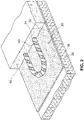
- a fleece cover layer 12 made of PES fibers (eg as recyclate or regenerated material) is laid out on the surface of the floor structure 10 and bonded to the floor structure 10 .
- the fleece cover layer 12 has a plurality of holes 14, 16, in particular punched out.
- a pipe 18 is laid on the non-woven cover layer 12, which can be a metal/plastic composite pipe, for example.
- the outside of the pipe 18 is provided with a particularly self-adhesive carrier tape with hooking elements 20 as one part of a hook-and-loop fastener system, the carrier tape running, for example, helically around the tube 18 .
- the hooking elements 20 interlock with the fibers 22 of the fleece cover layer 12 (only a few fibers 22 are indicated in the figures; however, the entire fleece cover layer 12 has fibers 22 throughout), whereby the pipe 18 to be laid is fixed.
- the fleece cover layer 12 forms a laying device 24.
- the fleece cover layer 12 has an upper layer 27 with hydrophobicized or hydrophobic fibers and is also provided with a lower layer 28 with PES melt fibers. Between these two layers and thus in the area 29 between them are PES fibers which do not necessarily have to be made hydrophobic or hydrophobic or designed as fusible fibers. The area weights and fiber counts of the PES fibers in the three aforementioned zones can be the same or different, as already described above.
- the upper surface of the nonwoven cover layer 12 is typically roughened, as indicated by the reference numeral 22.
- a screed 26 is then applied to the pipe 18 laid in this way or to the pipes 18 laid in this way forms the composite with the existing floor structure 10 and is otherwise separated from the floor structure 10 by the fleece cover layer 12 .
- a section of an underfloor heating structure is shown, in which heat and/or footfall sound insulation material 30 is first applied to the raw concrete.
- This material is laid out, for example, in the form of plates or webs arranged next to one another, whereupon a fleece cover layer 36 with PES fibers 38 is laid out as a laying device 32 for the pipe or pipes 34, which, like the fibers of the fleece cover layer 12 of the 1 described, are constituted.
- the fleece cover layer 36 can also be applied to the plates of the heat and/or footfall sound insulation at the factory.
- the tube 34 is in turn provided helically by a preferably self-adhesive carrier material with hooking elements 40 of a hook and loop fastener system, which hook onto the fibers 38 of the fleece cover layer 36 and thus fix the tube 34 to be laid.
- the fleece cover layer 36 is designed to be moisture-proof, which can be achieved, for example, by selecting the basis weight of the fleece and in particular the density of the fibers, a heat treatment of the fleece on the underside of the fleece cover layer with the aim of bonding the fibers Melting and subsequent cooling and the use of hydrophobic fibers depends.
Landscapes
- Engineering & Computer Science (AREA)
- Textile Engineering (AREA)
- Chemical & Material Sciences (AREA)
- Mechanical Engineering (AREA)
- Chemical Kinetics & Catalysis (AREA)
- Physics & Mathematics (AREA)
- Thermal Sciences (AREA)
- Combustion & Propulsion (AREA)
- General Engineering & Computer Science (AREA)
- Nonwoven Fabrics (AREA)
Applications Claiming Priority (1)
| Application Number | Priority Date | Filing Date | Title |
|---|---|---|---|
| DE202020106972 | 2020-12-03 |
Publications (1)
| Publication Number | Publication Date |
|---|---|
| EP4008968A1 true EP4008968A1 (fr) | 2022-06-08 |
Family
ID=78821060
Family Applications (1)
| Application Number | Title | Priority Date | Filing Date |
|---|---|---|---|
| EP21212134.7A Withdrawn EP4008968A1 (fr) | 2020-12-03 | 2021-12-03 | Dispositif de pose pour conduites d'un dispositif de régulation de la température de surface |
Country Status (2)
| Country | Link |
|---|---|
| EP (1) | EP4008968A1 (fr) |
| DE (1) | DE202021106602U1 (fr) |
Citations (8)
| Publication number | Priority date | Publication date | Assignee | Title |
|---|---|---|---|---|
| WO2006105836A1 (fr) * | 2005-04-04 | 2006-10-12 | Carl Freudenberg Kg | Non-tisse lie thermiquement |
| DE202010009431U1 (de) | 2010-06-23 | 2011-10-12 | Uponor Innovation Ab | System zur Anordnung mindestens eines Rohres |
| DE202014105276U1 (de) | 2014-11-04 | 2015-11-06 | herotec GmbH Flächenheizung | Fußbodendämmelement |
| DE202014104324U1 (de) * | 2014-09-12 | 2015-12-16 | Rehau Ag + Co. | Flexibles Kunststoffrohr sowie dieses umfassendes Flächentemperierungselement |
| DE202015100914U1 (de) | 2015-02-12 | 2016-05-13 | Uponor Innovation Ab | Dämmstoffmatte und Wärmetauscheranordnung |
| EP3141821A1 (fr) * | 2015-09-08 | 2017-03-15 | Lenzing Plastics GmbH & Co KG | Élement d'isolation de sous-sol |
| DE202016104752U1 (de) * | 2016-08-30 | 2017-12-04 | Uponor Innovation Ab | Fußbodendämmelement sowie Wärmetauscheranordnung |
| DE102018100374A1 (de) | 2017-01-09 | 2018-07-12 | herotec GmbH Flächenheizung | Verlegevorrichtung für Kühl- oder Heizmedium führende Rohre einer Flächentemperiervorrichtung |
-
2021
- 2021-12-03 EP EP21212134.7A patent/EP4008968A1/fr not_active Withdrawn
- 2021-12-03 DE DE202021106602.4U patent/DE202021106602U1/de active Active
Patent Citations (10)
| Publication number | Priority date | Publication date | Assignee | Title |
|---|---|---|---|---|
| WO2006105836A1 (fr) * | 2005-04-04 | 2006-10-12 | Carl Freudenberg Kg | Non-tisse lie thermiquement |
| DE202010009431U1 (de) | 2010-06-23 | 2011-10-12 | Uponor Innovation Ab | System zur Anordnung mindestens eines Rohres |
| DE202014104324U1 (de) * | 2014-09-12 | 2015-12-16 | Rehau Ag + Co. | Flexibles Kunststoffrohr sowie dieses umfassendes Flächentemperierungselement |
| DE202014105276U1 (de) | 2014-11-04 | 2015-11-06 | herotec GmbH Flächenheizung | Fußbodendämmelement |
| DE202015100914U1 (de) | 2015-02-12 | 2016-05-13 | Uponor Innovation Ab | Dämmstoffmatte und Wärmetauscheranordnung |
| EP3141821A1 (fr) * | 2015-09-08 | 2017-03-15 | Lenzing Plastics GmbH & Co KG | Élement d'isolation de sous-sol |
| DE202016104752U1 (de) * | 2016-08-30 | 2017-12-04 | Uponor Innovation Ab | Fußbodendämmelement sowie Wärmetauscheranordnung |
| DE102018100374A1 (de) | 2017-01-09 | 2018-07-12 | herotec GmbH Flächenheizung | Verlegevorrichtung für Kühl- oder Heizmedium führende Rohre einer Flächentemperiervorrichtung |
| EP3348916A1 (fr) * | 2017-01-09 | 2018-07-18 | herotec GmbH Flächenheizung | Dispositif de pose pour tuyaux guidant l'agent de refroidissement ou de chauffage d'un dispositif de thermoréglage de surfaces |
| DE202018006107U1 (de) | 2017-01-09 | 2019-03-27 | herotec GmbH Flächenheizung | Verlegevorrichtung für Kühl- oder Heizmedium führende Rohre einer Flächentemperiervorrichtung |
Also Published As
| Publication number | Publication date |
|---|---|
| DE202021106602U1 (de) | 2022-03-07 |
Similar Documents
| Publication | Publication Date | Title |
|---|---|---|
| EP0071213B1 (fr) | Objet stratifié pour la construction et son application | |
| AT12872U1 (de) | Klett-faserplatte | |
| EP3056823A2 (fr) | Panneau isolant et systeme d'echangeur thermique | |
| DE202008018155U1 (de) | Noppenplatte mit Filz | |
| EP3495743A1 (fr) | Dispositif d'isolation pour un dispositif de mise en température de surface et dispositif de mise en température de surface doté d'un tel dispositif d'isolation | |
| DE202018006107U1 (de) | Verlegevorrichtung für Kühl- oder Heizmedium führende Rohre einer Flächentemperiervorrichtung | |
| DE60013142T2 (de) | Dichtungsbahn | |
| EP2705198B1 (fr) | Mat thermiquement isolant, notamment pour la construction des bâtiments, et procédé pour sa production. | |
| EP3343082B1 (fr) | Système de régulation de température des surfaces | |
| EP4008968A1 (fr) | Dispositif de pose pour conduites d'un dispositif de régulation de la température de surface | |
| DE3922028C2 (fr) | ||
| DE3636207A1 (de) | Drainagelaminat | |
| EP0661153B1 (fr) | Matériau de garnissage résistant au percement des racines pour fixation sur un substrat | |
| EP0879326B1 (fr) | Panneau realise dans un materiau isolant | |
| EP0591658A1 (fr) | Elément d'isolation thermique et procédé pour sa fabrication | |
| EP3967936B1 (fr) | Surface de maintien pour un élément de thermorégulation de surface, ainsi que système de thermorégulation de surface comprenant une telle surface | |
| EP1122373B1 (fr) | Procédé de fabrication d'un matériau isolant en fibres minérales | |
| EP0073919A2 (fr) | Application d'un objet stratifié plat comme matière textile | |
| AT404749B (de) | Wasserdurchlässige wurzelbremsmatte | |
| DE9319699U1 (de) | Wärmedämmelement | |
| EP3425287B1 (fr) | Système de mise en température des surfaces | |
| DE4329957A1 (de) | Dränage-Matte | |
| DE102004054099A1 (de) | Trittschalldämmung | |
| DE19749615C2 (de) | Isolationsschlauch | |
| DE10022405B4 (de) | Verfahren zur Herstellung eines Textilschlauches für die Ummantelung von Rohren |
Legal Events
| Date | Code | Title | Description |
|---|---|---|---|
| PUAI | Public reference made under article 153(3) epc to a published international application that has entered the european phase |
Free format text: ORIGINAL CODE: 0009012 |
|
| STAA | Information on the status of an ep patent application or granted ep patent |
Free format text: STATUS: THE APPLICATION HAS BEEN PUBLISHED |
|
| AK | Designated contracting states |
Kind code of ref document: A1 Designated state(s): AL AT BE BG CH CY CZ DE DK EE ES FI FR GB GR HR HU IE IS IT LI LT LU LV MC MK MT NL NO PL PT RO RS SE SI SK SM TR |
|
| STAA | Information on the status of an ep patent application or granted ep patent |
Free format text: STATUS: THE APPLICATION IS DEEMED TO BE WITHDRAWN |
|
| 18D | Application deemed to be withdrawn |
Effective date: 20221209 |