EP4008986A1 - Silencieux destiné à être monté sur un canon d'arme à feu - Google Patents
Silencieux destiné à être monté sur un canon d'arme à feu Download PDFInfo
- Publication number
- EP4008986A1 EP4008986A1 EP21211312.0A EP21211312A EP4008986A1 EP 4008986 A1 EP4008986 A1 EP 4008986A1 EP 21211312 A EP21211312 A EP 21211312A EP 4008986 A1 EP4008986 A1 EP 4008986A1
- Authority
- EP
- European Patent Office
- Prior art keywords
- silencer
- housing
- clamping device
- barrel
- gun barrel
- Prior art date
- Legal status (The legal status is an assumption and is not a legal conclusion. Google has not performed a legal analysis and makes no representation as to the accuracy of the status listed.)
- Granted
Links
Images
Classifications
-
- F—MECHANICAL ENGINEERING; LIGHTING; HEATING; WEAPONS; BLASTING
- F41—WEAPONS
- F41A—FUNCTIONAL FEATURES OR DETAILS COMMON TO BOTH SMALLARMS AND ORDNANCE, e.g. CANNONS; MOUNTINGS FOR SMALLARMS OR ORDNANCE
- F41A21/00—Barrels; Gun tubes; Muzzle attachments; Barrel mounting means
- F41A21/32—Muzzle attachments or glands
-
- F—MECHANICAL ENGINEERING; LIGHTING; HEATING; WEAPONS; BLASTING
- F41—WEAPONS
- F41A—FUNCTIONAL FEATURES OR DETAILS COMMON TO BOTH SMALLARMS AND ORDNANCE, e.g. CANNONS; MOUNTINGS FOR SMALLARMS OR ORDNANCE
- F41A21/00—Barrels; Gun tubes; Muzzle attachments; Barrel mounting means
- F41A21/30—Silencers
Definitions
- the invention relates to a silencer for mounting on a weapon barrel, having a silencer housing for completely enclosing the weapon barrel at least in sections.
- silencers also called muzzle signature reducers
- muzzle signature reducers are devices arranged at the muzzle of a gun barrel of the firearm to reduce noise emissions and muzzle flash.
- silencers can also reduce recoil when the shot is fired, which, together with the mass of the silencer, reduces the firearm's muzzle roll.
- the precision of long guns is increased, since silencers have a positive, physical influence on the (propellant/combustion) gases that follow the bullet.
- a silencer changes the sound of the muzzle blast.
- silencers reduce the volume of the muzzle blast and thus reduce the risk of hearing damage in hunters, beaters and dogs, for example.
- silencers do not restrict three-dimensional hearing.
- Such silencers are often designed as barrel attachments that can be screwed on.
- the silencers here have an internal thread which can be screwed onto a corresponding external thread of a weapon barrel (muzzle thread) on the end face (muzzle side).
- these threads are often formed with a fine thread. For example, if dirt gets to this during a hunt fine thread, this makes it more difficult or even impossible to attach the silencer.
- the invention is based on the object of specifying a particularly suitable silencer for mounting on a gun barrel.
- a simple and cost-reduced assembly should also be made possible on gun barrels without a muzzle thread.
- the silencer according to the invention is intended for mounting on a gun barrel and is suitable and set up for this.
- the silencer is preferably designed as a barrel attachment that can be placed on a gun barrel or a muzzle of a gun, in particular a hand-held gun, preferably a hunting rifle.
- the silencer has a silencer housing which, in the assembled state, completely encloses the weapon barrel at least in sections.
- the silencer housing has an integrated jacket tube, which preferably encloses the weapon barrel in the assembled state.
- a muzzle brake is accommodated in the silencer housing, which keeps the jacket tube centered in the silencer housing.
- the muzzle brake is provided and set up to use the energy of the combustion gases (propellant gases) produced when a shot is fired in order to reduce the recoil of the firearm.
- the silencer also has a device for deflecting and/or cooling the gases produced when a shot is fired, as a result of which the muzzle blast and muzzle flash are reduced.
- the silencer has a clamping device for positively and/or non-positively locking the weapon barrel.
- a clamping device for positively and/or non-positively locking the weapon barrel.
- a non-destructive clamp attachment of the silencer on the gun barrel is provided, so the gun barrel is clamped by the clamping device.
- a "positive fit” or a "positive connection” between at least two parts connected to one another is understood here and in the following in particular to mean that the parts connected to one another are held together at least in one direction by direct interlocking of the contours of the parts themselves or by indirect interlocking via an additional connector. The "blocking" of a mutual movement in this direction is therefore due to the shape.
- a “positive connection” or a “positive connection” between at least two parts connected to one another is understood here and in the following in particular to mean that the parts connected to one another are prevented from sliding off one another due to a frictional force acting between them. If there is no "connection force” that causes this frictional force (this means the force that presses the parts against one another, for example a screw force or the force of weight itself), the non-positive connection cannot be maintained and can therefore be released.
- the silencer is preferably completely manually dismantled and can be assembled by a user without any risk.
- the clamping device is designed as a collet.
- the collet has here, for example, an externally conical, radially slotted, sleeve with a central bore as a receptacle or Through hole for the gun barrel.
- the sleeve or the bore are here adapted to the respective barrel diameter of the gun barrel.
- the collet is clamped onto the gun barrel, for example by means of a key or lever. This ensures a particularly stable and reliable attachment of the silencer. In particular, a cost-reduced and always centering clamping of the gun barrel is thus realized.
- the clamping device is arranged on an end face of the muffler housing.
- the clamping device is arranged on a side of the muffler housing opposite the outlet opening.
- the end face is designed, for example, as a removable housing cover.
- the silencer is designed, for example, as an integral silencer, with the silencer housing not only being placed on the barrel muzzle, but rather extending essentially completely over the gun barrel in its longitudinal direction and enclosing it at least in sections like a jacket.
- This optimizes a damping performance of the muffler.
- a center of gravity of the silencer is shifted to the rear, ie in the direction of the firearm and away from the muzzle of the gun barrel.
- the silencer thus has a particularly space-compact structure in front of the muzzle barrel, as a result of which the handling and balance of the firearm equipped with it is significantly improved.
- the end face of the muffler housing is provided with an internal thread into which an external thread of the clamping device is screwed or can be screwed.
- the clamping device or the collets are screwed into the end face or the housing cover.
- the clamping device has at least one seal on an inner circumference surrounding or enclosing the gun barrel.
- the clamping device—and thus the silencer— is sealed by means of the seal relative to the outer circumference of the gun barrel, in particular in a gas-tight manner.
- the seal also increases the frictional resistance and thus the non-positive holding force on the gun barrel.
- the at least one seal allows the jacket pipe not to be permanently installed inside the muffler housing, as a result of which a larger expansion chamber can be implemented. This further improves the muffling performance of the muffler.
- An additional or further aspect of the invention provides a centering sleeve for centering the weapon barrel, which is arranged on an end face of the jacket tube facing the muzzle brake.
- the silencer is thus centered on the bore axis of the gun barrel via the centering sleeve.
- the gun barrel is thus held at two points by the centering sleeve and the clamping device.
- the muzzle brake is screwed to the jacket tube.
- the muzzle brake is screwed to the jacket tube on the outside, for which purpose the jacket tube has an internal thread and the muzzle brake has an external thread.
- the device has a (baffle wall) chamber with a number of baffle walls and/or a (gas rotation) chamber with a gas rotation insert.
- the device preferably has both a baffle chamber and a gas rotation chamber, which are connected downstream of one another. This enables a reliable reduction of noise emissions and the muzzle flash.
- the baffle walls are designed here, for example, as reflection surfaces for the combustion gases.
- the propellant gases of the projectile escaping from the muzzle are slowed down and cooled, which leads to a reduction in the muzzle blast and muzzle flash.
- the baffle walls are each designed, for example, as the envelope of a cone and have, for example, an opening angle of approximately 45°.
- the rotary gas insert has a significant influence on the damping performance of the muffler. Due to the (gas) rotation insert, the gases are cooled very quickly and the muzzle blast is swirled.
- the rotary insert preferably has a shape or geometry that achieves a particularly high damping performance in as compact a space as possible.
- the gas rotation insert is produced as an exchangeable 3D printed part.
- the rotary gas insert is manufactured using a three-dimensional printing process, a particularly effective and suitable shape and geometry in terms of damping performance is made possible. This makes it possible to produce the silencer in much shorter designs, which brings a significant advantage for the handling of a firearm equipped with it.
- the silencer Due to the exchangeability or interchangeability of the rotary gas insert, it is also possible to adapt the silencer flexibly to a respective caliber of the firearm. For example, when the caliber is changed, only the rotary gas insert needs to be replaced.
- an intermediate space is formed as an expansion chamber between the muffler housing and the casing tube, with the muffler housing having at least one ventilation hole for the intermediate space.
- the ventilation hole can also be part of the device, for example. Cold air can escape from the expansion chamber through the ventilation hole, so that the hot (combustion/drive) gases can spread out faster and be cooled down. This further improves the muffling performance of the muffler.
- moisture can escape from the jacket pipe.
- moisture is to be understood here and in the following in particular as the presence of water, in particular in the form of water vapor from atmospheric moisture in the air enclosed in the casing tube. This means that there can be unbound water content inside the casing tube, which can react chemically with powder residues, for example, and can lead to damage or corrosion.
- the ventilation hole ensures that moisture is removed can escape through the mandrel, improving the life of the mandrel and thus the muffler.
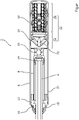
- the figure shows a perspective sectional view of a silencer 2, which is mounted on the muzzle side on a gun barrel 4 of a firearm, not shown in detail.
- the firearm is a hunting rifle.
- the gun barrel 4 has no muzzle thread. In other words, the gun barrel 4 is therefore designed without a thread.
- the silencer 2 is designed in particular as an integral silencer and has a cylindrical or tubular silencer housing 6 as an outer jacket tube, which completely encloses the weapon barrel 4 in sections.
- An (inner) jacket tube 8 is accommodated in the silencer housing 6 and coaxially encloses the weapon barrel 4 .
- the jacket tube 8 is held centered in the silencer housing 6 on the one hand by means of a muzzle brake 10 .
- the casing tube 8 sits in a receptacle (not designated in any more detail) of an annular housing cover 12 which closes the muffler housing 6 at one end.
- the muzzle brake 10 engages at least in sections in the jacket tube 8, with a centering sleeve 14 being arranged in the engaging region of the muzzle brake 10, by means of which the gun barrel 4 is aligned on the muzzle side, centered in the jacket tube 8 or the silencer housing 6.
- the muzzle brake 10 is provided with an external thread in the engaging area, which is screwed into a corresponding internal thread of the jacket tube 8 .
- the housing cover 12 has a threaded hole on the outside of the housing, into which a clamping device 16 designed as a collet is screwed.
- the clamping device 16 has an external thread Mounting portion, which is screwed into the internal thread of the threaded bore. The clamping device 16 fixes the silencer 2 in the assembled state in a positive and/or non-positive manner on the gun barrel 4.
- the clamping device 16 has four axially distributed seals 18 which are arranged as radial ring seals on a weapon barrel 4 surrounding or enclosing the clamping device 16 .
- the clamping device 16 and thus the silencer 2—is sealed by means of the seals 18 relative to the outer circumference of the weapon barrel 4, in particular in a gas-tight manner.
- the forces of the gas pressure of the combustion gases on the one hand and the clamping or clamping effect of the clamping device 16 or collet chuck on the other hand are absorbed by the seals 18 .
- the seals 18 also increase the frictional resistance and thus the non-positive holding force on the gun barrel 4.
- Axial or an “axial direction” is understood here and in the following in particular as a direction parallel (coaxial) to the gun barrel 4 , that is to say perpendicular to the end faces of the silencer 2 .
- radial or a “radial direction” is understood to mean, in particular, a direction oriented perpendicular (transverse) to the longitudinal axis of the gun barrel 4 along a radius of the gun barrel 4 or the silencer 2 .
- tangential or a “tangential direction” means in particular a direction along the circumference of the silencer 2 or the gun barrel 4 (circumferential direction, azimuthal direction), i.e. a direction perpendicular to the axial direction and to the radial direction.
- the figure also shows a projectile 20 fired from the gun barrel 4, which is shown in the area of a device 22 for deflecting and/or cooling a (propellant/combustion) gas produced when a shot is fired.
- the device 22 here has a baffle wall chamber 24 and a gas rotation chamber 26, which adjoin the muzzle brake 10 in axial succession.
- the baffle wall chamber 24 has, for example, two baffle walls 28 arranged one behind the other.
- the impact walls 28 are each designed, for example, as a cone envelope of a cone and have, for example, an opening angle of approximately 45°.
- An approximately hollow-cylindrical gas rotation insert 30 is accommodated in the gas rotation chamber 26 .
- the gas rotation insert 30 preferably has a shape or geometry that achieves a particularly high damping performance in as compact a space as possible.
- the gas rotation insert 30 is manufactured as an interchangeable 3D printed part.
- an unspecified intermediate space is formed as an expansion chamber.
- the muffler housing 6 has at least one ventilation hole 32 which penetrates the muffler housing 6 approximately radially and thus couples the expansion chamber or the intermediate space with the environment. Cold air can escape from the expansion chamber through the ventilation hole 32, so that the hot (combustion/motive) gases can spread and be cooled more quickly.
- the silencer 2 can preferably be completely dismantled manually and assembled by a user without any risk.
Landscapes
- Engineering & Computer Science (AREA)
- General Engineering & Computer Science (AREA)
- Exhaust Silencers (AREA)
- Portable Nailing Machines And Staplers (AREA)
- Toys (AREA)
- Clamps And Clips (AREA)
Priority Applications (2)
| Application Number | Priority Date | Filing Date | Title |
|---|---|---|---|
| HRP20240528TT HRP20240528T1 (hr) | 2020-12-02 | 2021-11-30 | Prigušivač za montažu na cijev oružja |
| RS20240443A RS65461B1 (sr) | 2020-12-02 | 2021-11-30 | Prigušivač za montažu na cev oružja |
Applications Claiming Priority (1)
| Application Number | Priority Date | Filing Date | Title |
|---|---|---|---|
| DE102020132017.5A DE102020132017A1 (de) | 2020-12-02 | 2020-12-02 | Schalldämpfer zur Montage an einem Waffenlauf |
Publications (3)
| Publication Number | Publication Date |
|---|---|
| EP4008986A1 true EP4008986A1 (fr) | 2022-06-08 |
| EP4008986B1 EP4008986B1 (fr) | 2024-01-17 |
| EP4008986C0 EP4008986C0 (fr) | 2024-01-17 |
Family
ID=78820062
Family Applications (1)
| Application Number | Title | Priority Date | Filing Date |
|---|---|---|---|
| EP21211312.0A Active EP4008986B1 (fr) | 2020-12-02 | 2021-11-30 | Silencieux destiné à être monté sur un canon d'arme à feu |
Country Status (8)
| Country | Link |
|---|---|
| US (1) | US11644266B2 (fr) |
| EP (1) | EP4008986B1 (fr) |
| CA (1) | CA3141046A1 (fr) |
| DE (1) | DE102020132017A1 (fr) |
| HR (1) | HRP20240528T1 (fr) |
| HU (1) | HUE066431T2 (fr) |
| PL (1) | PL4008986T3 (fr) |
| RS (1) | RS65461B1 (fr) |
Families Citing this family (4)
| Publication number | Priority date | Publication date | Assignee | Title |
|---|---|---|---|---|
| US11698239B2 (en) * | 2021-01-04 | 2023-07-11 | Eight Holdings LLC | Muzzle device for a firearm |
| US12135180B2 (en) * | 2022-08-04 | 2024-11-05 | WHG Properties, LLC | Firearm suppressor |
| US12264889B2 (en) | 2023-01-13 | 2025-04-01 | Replicator LLC | Suppressor for a firearm |
| US20250137761A1 (en) * | 2023-10-27 | 2025-05-01 | Scott Bell | Firearm sound suppression device |
Citations (5)
| Publication number | Priority date | Publication date | Assignee | Title |
|---|---|---|---|---|
| US6385891B1 (en) * | 2000-04-04 | 2002-05-14 | Robert Rabatin | Adapter for attaching sound suppressors or other auxiliary devices to weapons |
| US20160161203A1 (en) * | 2012-12-21 | 2016-06-09 | Bert John WILSON | Suppressors and their methods of manufacture |
| DE202016006589U1 (de) * | 2016-10-25 | 2018-01-21 | Tim Enderle | Gasumlenker im 120° Winkel, verbunden mit einem Schalldämpfer für Langwaffen |
| DE202017101110U1 (de) * | 2017-02-28 | 2018-05-29 | L&O Hunting Group GmbH | Integralschalldämpfer für einen Gewehrlauf |
| US10082354B1 (en) * | 2018-02-21 | 2018-09-25 | Darryl S. Lee | Firearm suppressor adapter for barrels having obstructions |
Family Cites Families (23)
| Publication number | Priority date | Publication date | Assignee | Title |
|---|---|---|---|---|
| US1435084A (en) * | 1921-06-09 | 1922-11-07 | Schneider & Cie | Apparatus for reducing the length of recoil in guns |
| IT1194990B (it) | 1981-09-30 | 1988-09-28 | Beretta Armi Spa | Dispositivo di fissaggio del silenziatore ad armi portatili |
| US5136923A (en) * | 1982-07-30 | 1992-08-11 | Walsh Donald J Jun | Firearm silencer and flash attenuator |
| US4939977A (en) * | 1989-06-07 | 1990-07-10 | Stroup Larry J | Gun silencer and muzzle protector |
| US7676976B2 (en) * | 2003-11-06 | 2010-03-16 | Surefire, Llc | Systems for attaching a noise suppressor to a firearm |
| US20080098880A1 (en) | 2005-06-30 | 2008-05-01 | Karl Brugger | Lock/rotation mounted suppressor |
| US7588122B2 (en) * | 2007-08-20 | 2009-09-15 | Kevin Tyson Brittingham | Orientation apparatus for eccentric firearm noise suppressor and assembly method |
| US20090193963A1 (en) * | 2007-09-11 | 2009-08-06 | Poulsen Peter Ostergaard | Joint between a sound suppressor and a barrel of a firearm |
| US8291805B1 (en) * | 2010-03-10 | 2012-10-23 | Quilligan Jay J | Quick-attach locking device for a flash hider |
| US9658019B2 (en) | 2014-09-19 | 2017-05-23 | Ra Brands, L.L.C. | Silencer and mounting system |
| US9927201B2 (en) * | 2014-10-03 | 2018-03-27 | Alexander Nikolaevich PENCHUK | Barrel coupling for firearm |
| DE102016000437A1 (de) | 2016-01-18 | 2017-07-20 | Prime Manufacturing Group Limited (BVI) | Einrichtung zum lösbaren Befestigen eines Schalldämpfers und Schalldämpferanordnung |
| EP3208567B1 (fr) | 2016-02-18 | 2019-04-10 | Martin Ernsperger | Amortisseur de bruit |
| US10330420B2 (en) * | 2017-02-21 | 2019-06-25 | Nemo Arms, Inc. | Suppressor assembly |
| US10527379B2 (en) * | 2017-04-27 | 2020-01-07 | Dbdrop Inc. | Firearm adapter |
| US9891017B1 (en) * | 2017-05-22 | 2018-02-13 | Darryl S. Lee | Firearm suppressor adapter |
| US10066890B1 (en) * | 2017-04-27 | 2018-09-04 | Darryl S. Lee | Firearm suppressor adapter |
| US10969188B1 (en) | 2018-12-04 | 2021-04-06 | Brent R. Cottingham | Pistol slide-mounted suppressor |
| DE102019000223A1 (de) | 2019-01-16 | 2020-07-16 | Voere Holding Gmbh | Klemmdämpfer für eine Waffe |
| US11397065B2 (en) * | 2019-10-04 | 2022-07-26 | Silention Oy | Silencer for a firearm |
| US11112200B2 (en) * | 2019-11-04 | 2021-09-07 | Earth Outdoor Tactical L.L.C. | Suppressor |
| US20210404760A1 (en) * | 2020-06-02 | 2021-12-30 | Aaron Hipp | Adjustable tuning device |
| US11662172B2 (en) * | 2020-08-30 | 2023-05-30 | Keith A. Langenbeck | Integrated barrel and muzzle device system |
-
2020
- 2020-12-02 DE DE102020132017.5A patent/DE102020132017A1/de active Pending
-
2021
- 2021-11-30 EP EP21211312.0A patent/EP4008986B1/fr active Active
- 2021-11-30 HU HUE21211312A patent/HUE066431T2/hu unknown
- 2021-11-30 HR HRP20240528TT patent/HRP20240528T1/hr unknown
- 2021-11-30 RS RS20240443A patent/RS65461B1/sr unknown
- 2021-11-30 PL PL21211312.0T patent/PL4008986T3/pl unknown
- 2021-12-02 US US17/540,627 patent/US11644266B2/en active Active
- 2021-12-02 CA CA3141046A patent/CA3141046A1/fr active Pending
Patent Citations (5)
| Publication number | Priority date | Publication date | Assignee | Title |
|---|---|---|---|---|
| US6385891B1 (en) * | 2000-04-04 | 2002-05-14 | Robert Rabatin | Adapter for attaching sound suppressors or other auxiliary devices to weapons |
| US20160161203A1 (en) * | 2012-12-21 | 2016-06-09 | Bert John WILSON | Suppressors and their methods of manufacture |
| DE202016006589U1 (de) * | 2016-10-25 | 2018-01-21 | Tim Enderle | Gasumlenker im 120° Winkel, verbunden mit einem Schalldämpfer für Langwaffen |
| DE202017101110U1 (de) * | 2017-02-28 | 2018-05-29 | L&O Hunting Group GmbH | Integralschalldämpfer für einen Gewehrlauf |
| US10082354B1 (en) * | 2018-02-21 | 2018-09-25 | Darryl S. Lee | Firearm suppressor adapter for barrels having obstructions |
Also Published As
| Publication number | Publication date |
|---|---|
| RS65461B1 (sr) | 2024-05-31 |
| EP4008986B1 (fr) | 2024-01-17 |
| US11644266B2 (en) | 2023-05-09 |
| HRP20240528T1 (hr) | 2024-07-05 |
| HUE066431T2 (hu) | 2024-08-28 |
| DE102020132017A1 (de) | 2022-06-02 |
| PL4008986T3 (pl) | 2024-07-08 |
| EP4008986C0 (fr) | 2024-01-17 |
| US20220170712A1 (en) | 2022-06-02 |
| CA3141046A1 (fr) | 2022-06-02 |
Similar Documents
| Publication | Publication Date | Title |
|---|---|---|
| EP4008986B1 (fr) | Silencieux destiné à être monté sur un canon d'arme à feu | |
| EP2867607B1 (fr) | Silencieux pour une arme portative | |
| DE4231183C1 (de) | Schalldämpfer für Feuerwaffen | |
| EP0071799B1 (fr) | Arme à feu portative munie d'un silencieux | |
| US8342071B2 (en) | Firearm flash suppressor | |
| US20190154387A1 (en) | Firearm Adapter | |
| US11828557B2 (en) | Suppressor | |
| US20120246987A1 (en) | Recoil, sound and flash suppressor | |
| EP3367042B1 (fr) | Amortisseur de bruit intégré pour un canon d'un fusil | |
| US11162754B2 (en) | Integrally suppressed barrel | |
| DE102011010639B4 (de) | Schalldämpfer für eine Handfeuerwaffe | |
| DE102011116059A1 (de) | Schalldämpfer für eine Handfeuerwaffe | |
| US10508879B1 (en) | Device for dampening residual effects from a firearm suppressor | |
| DE202014004278U1 (de) | Modulschalldämpfer für Feuerwaffen | |
| DE202017101110U1 (de) | Integralschalldämpfer für einen Gewehrlauf | |
| EP3800433B1 (fr) | Silencieux pour une arme à feu | |
| WO2021008658A1 (fr) | Compensateur | |
| BG3438U1 (bg) | Супресор | |
| EP3992566B1 (fr) | Silencieux pour une arme de poing | |
| DE3430521A1 (de) | Vorsatzkuehlturbine fuer druckgas- oder druckfluessigkeitenfuehrende rohrkoerper | |
| EP2769166A1 (fr) | Silencieux avec surface de prise pour un outil | |
| CA2666528C (fr) | Suppresseur de feu de bouche d'arme a feu | |
| DE102021003389A1 (de) | Waffenschalldämpfer | |
| DE8424592U1 (de) | Vorsatzkühlturbine für druckgas- oder druckflüssigkeitenführende Rohrkörper | |
| DE202013004331U1 (de) | Schalldämpfer mit lmpulsgeber für Handfeuerwaffen (Lang- und Kurzwaffen) |
Legal Events
| Date | Code | Title | Description |
|---|---|---|---|
| REG | Reference to a national code |
Ref country code: HR Ref legal event code: TUEP Ref document number: P20240528T Country of ref document: HR |
|
| PUAI | Public reference made under article 153(3) epc to a published international application that has entered the european phase |
Free format text: ORIGINAL CODE: 0009012 |
|
| STAA | Information on the status of an ep patent application or granted ep patent |
Free format text: STATUS: THE APPLICATION HAS BEEN PUBLISHED |
|
| AK | Designated contracting states |
Kind code of ref document: A1 Designated state(s): AL AT BE BG CH CY CZ DE DK EE ES FI FR GB GR HR HU IE IS IT LI LT LU LV MC MK MT NL NO PL PT RO RS SE SI SK SM TR |
|
| STAA | Information on the status of an ep patent application or granted ep patent |
Free format text: STATUS: REQUEST FOR EXAMINATION WAS MADE |
|
| 17P | Request for examination filed |
Effective date: 20221208 |
|
| RBV | Designated contracting states (corrected) |
Designated state(s): AL AT BE BG CH CY CZ DE DK EE ES FI FR GB GR HR HU IE IS IT LI LT LU LV MC MK MT NL NO PL PT RO RS SE SI SK SM TR |
|
| GRAP | Despatch of communication of intention to grant a patent |
Free format text: ORIGINAL CODE: EPIDOSNIGR1 |
|
| STAA | Information on the status of an ep patent application or granted ep patent |
Free format text: STATUS: GRANT OF PATENT IS INTENDED |
|
| INTG | Intention to grant announced |
Effective date: 20230905 |
|
| P01 | Opt-out of the competence of the unified patent court (upc) registered |
Effective date: 20230911 |
|
| GRAS | Grant fee paid |
Free format text: ORIGINAL CODE: EPIDOSNIGR3 |
|
| GRAA | (expected) grant |
Free format text: ORIGINAL CODE: 0009210 |
|
| STAA | Information on the status of an ep patent application or granted ep patent |
Free format text: STATUS: THE PATENT HAS BEEN GRANTED |
|
| AK | Designated contracting states |
Kind code of ref document: B1 Designated state(s): AL AT BE BG CH CY CZ DE DK EE ES FI FR GB GR HR HU IE IS IT LI LT LU LV MC MK MT NL NO PL PT RO RS SE SI SK SM TR |
|
| REG | Reference to a national code |
Ref country code: GB Ref legal event code: FG4D Free format text: NOT ENGLISH |
|
| REG | Reference to a national code |
Ref country code: CH Ref legal event code: EP |
|
| REG | Reference to a national code |
Ref country code: DE Ref legal event code: R096 Ref document number: 502021002488 Country of ref document: DE |
|
| REG | Reference to a national code |
Ref country code: IE Ref legal event code: FG4D Free format text: LANGUAGE OF EP DOCUMENT: GERMAN |
|
| U01 | Request for unitary effect filed |
Effective date: 20240214 |
|
| P04 | Withdrawal of opt-out of the competence of the unified patent court (upc) registered |
Effective date: 20240219 |
|
| U07 | Unitary effect registered |
Designated state(s): AT BE BG DE DK EE FI FR IT LT LU LV MT NL PT SE SI Effective date: 20240222 |
|
| REG | Reference to a national code |
Ref country code: SK Ref legal event code: T3 Ref document number: E 43918 Country of ref document: SK |
|
| PG25 | Lapsed in a contracting state [announced via postgrant information from national office to epo] |
Ref country code: IS Free format text: LAPSE BECAUSE OF FAILURE TO SUBMIT A TRANSLATION OF THE DESCRIPTION OR TO PAY THE FEE WITHIN THE PRESCRIBED TIME-LIMIT Effective date: 20240517 |
|
| REG | Reference to a national code |
Ref country code: HR Ref legal event code: T1PR Ref document number: P20240528 Country of ref document: HR |
|
| PG25 | Lapsed in a contracting state [announced via postgrant information from national office to epo] |
Ref country code: GR Free format text: LAPSE BECAUSE OF FAILURE TO SUBMIT A TRANSLATION OF THE DESCRIPTION OR TO PAY THE FEE WITHIN THE PRESCRIBED TIME-LIMIT Effective date: 20240418 |
|
| PG25 | Lapsed in a contracting state [announced via postgrant information from national office to epo] |
Ref country code: ES Free format text: LAPSE BECAUSE OF FAILURE TO SUBMIT A TRANSLATION OF THE DESCRIPTION OR TO PAY THE FEE WITHIN THE PRESCRIBED TIME-LIMIT Effective date: 20240117 |
|
| PG25 | Lapsed in a contracting state [announced via postgrant information from national office to epo] |
Ref country code: IS Free format text: LAPSE BECAUSE OF FAILURE TO SUBMIT A TRANSLATION OF THE DESCRIPTION OR TO PAY THE FEE WITHIN THE PRESCRIBED TIME-LIMIT Effective date: 20240517 Ref country code: GR Free format text: LAPSE BECAUSE OF FAILURE TO SUBMIT A TRANSLATION OF THE DESCRIPTION OR TO PAY THE FEE WITHIN THE PRESCRIBED TIME-LIMIT Effective date: 20240418 Ref country code: ES Free format text: LAPSE BECAUSE OF FAILURE TO SUBMIT A TRANSLATION OF THE DESCRIPTION OR TO PAY THE FEE WITHIN THE PRESCRIBED TIME-LIMIT Effective date: 20240117 |
|
| REG | Reference to a national code |
Ref country code: HU Ref legal event code: AG4A Ref document number: E066431 Country of ref document: HU |
|
| PG25 | Lapsed in a contracting state [announced via postgrant information from national office to epo] |
Ref country code: SM Free format text: LAPSE BECAUSE OF FAILURE TO SUBMIT A TRANSLATION OF THE DESCRIPTION OR TO PAY THE FEE WITHIN THE PRESCRIBED TIME-LIMIT Effective date: 20240117 |
|
| REG | Reference to a national code |
Ref country code: DE Ref legal event code: R097 Ref document number: 502021002488 Country of ref document: DE |
|
| PG25 | Lapsed in a contracting state [announced via postgrant information from national office to epo] |
Ref country code: SM Free format text: LAPSE BECAUSE OF FAILURE TO SUBMIT A TRANSLATION OF THE DESCRIPTION OR TO PAY THE FEE WITHIN THE PRESCRIBED TIME-LIMIT Effective date: 20240117 |
|
| PLBE | No opposition filed within time limit |
Free format text: ORIGINAL CODE: 0009261 |
|
| STAA | Information on the status of an ep patent application or granted ep patent |
Free format text: STATUS: NO OPPOSITION FILED WITHIN TIME LIMIT |
|
| REG | Reference to a national code |
Ref country code: HR Ref legal event code: ODRP Ref document number: P20240528 Country of ref document: HR Payment date: 20241120 Year of fee payment: 4 |
|
| 26N | No opposition filed |
Effective date: 20241018 |
|
| U20 | Renewal fee for the european patent with unitary effect paid |
Year of fee payment: 4 Effective date: 20241126 |
|
| P05 | Withdrawal of opt-out of the competence of the unified patent court (upc) changed |
Free format text: CASE NUMBER: APP_8902/2024 Effective date: 20240222 |
|
| PGFP | Annual fee paid to national office [announced via postgrant information from national office to epo] |
Ref country code: HU Payment date: 20241122 Year of fee payment: 4 |
|
| PGFP | Annual fee paid to national office [announced via postgrant information from national office to epo] |
Ref country code: NO Payment date: 20241119 Year of fee payment: 4 |
|
| PGFP | Annual fee paid to national office [announced via postgrant information from national office to epo] |
Ref country code: PL Payment date: 20241118 Year of fee payment: 4 |
|
| PGFP | Annual fee paid to national office [announced via postgrant information from national office to epo] |
Ref country code: CZ Payment date: 20241115 Year of fee payment: 4 Ref country code: HR Payment date: 20241120 Year of fee payment: 4 |
|
| PGFP | Annual fee paid to national office [announced via postgrant information from national office to epo] |
Ref country code: RO Payment date: 20241126 Year of fee payment: 4 Ref country code: SK Payment date: 20241118 Year of fee payment: 4 |
|
| PGFP | Annual fee paid to national office [announced via postgrant information from national office to epo] |
Ref country code: RS Payment date: 20241115 Year of fee payment: 4 |
|
| PGFP | Annual fee paid to national office [announced via postgrant information from national office to epo] |
Ref country code: CH Payment date: 20241201 Year of fee payment: 4 |
|
| PGFP | Annual fee paid to national office [announced via postgrant information from national office to epo] |
Ref country code: TR Payment date: 20241120 Year of fee payment: 4 |
|
| PG25 | Lapsed in a contracting state [announced via postgrant information from national office to epo] |
Ref country code: MC Free format text: LAPSE BECAUSE OF FAILURE TO SUBMIT A TRANSLATION OF THE DESCRIPTION OR TO PAY THE FEE WITHIN THE PRESCRIBED TIME-LIMIT Effective date: 20240117 |
|
| PG25 | Lapsed in a contracting state [announced via postgrant information from national office to epo] |
Ref country code: IE Free format text: LAPSE BECAUSE OF NON-PAYMENT OF DUE FEES Effective date: 20241130 |
|
| PG25 | Lapsed in a contracting state [announced via postgrant information from national office to epo] |
Ref country code: CY Free format text: LAPSE BECAUSE OF FAILURE TO SUBMIT A TRANSLATION OF THE DESCRIPTION OR TO PAY THE FEE WITHIN THE PRESCRIBED TIME-LIMIT; INVALID AB INITIO Effective date: 20211130 |