EP4009057B1 - Kontaktlose strommessvorrichtung mit flexiblem magnetkern - Google Patents
Kontaktlose strommessvorrichtung mit flexiblem magnetkern Download PDFInfo
- Publication number
- EP4009057B1 EP4009057B1 EP21210841.9A EP21210841A EP4009057B1 EP 4009057 B1 EP4009057 B1 EP 4009057B1 EP 21210841 A EP21210841 A EP 21210841A EP 4009057 B1 EP4009057 B1 EP 4009057B1
- Authority
- EP
- European Patent Office
- Prior art keywords
- frequency
- measuring device
- current
- typically
- fpol
- Prior art date
- Legal status (The legal status is an assumption and is not a legal conclusion. Google has not performed a legal analysis and makes no representation as to the accuracy of the status listed.)
- Active
Links
Images


Classifications
-
- G—PHYSICS
- G01—MEASURING; TESTING
- G01R—MEASURING ELECTRIC VARIABLES; MEASURING MAGNETIC VARIABLES
- G01R15/00—Details of measuring arrangements of the types provided for in groups G01R17/00 - G01R29/00, G01R33/00 - G01R33/26 or G01R35/00
- G01R15/14—Adaptations providing voltage or current isolation, e.g. for high-voltage or high-current networks
- G01R15/18—Adaptations providing voltage or current isolation, e.g. for high-voltage or high-current networks using inductive devices, e.g. transformers
- G01R15/183—Adaptations providing voltage or current isolation, e.g. for high-voltage or high-current networks using inductive devices, e.g. transformers using transformers with a magnetic core
-
- H—ELECTRICITY
- H01—ELECTRIC ELEMENTS
- H01F—MAGNETS; INDUCTANCES; TRANSFORMERS; SELECTION OF MATERIALS FOR THEIR MAGNETIC PROPERTIES
- H01F38/00—Adaptations of transformers or inductances for specific applications or functions
- H01F38/20—Instruments transformers
- H01F38/22—Instruments transformers for single phase AC
- H01F38/28—Current transformers
- H01F38/30—Constructions
-
- H—ELECTRICITY
- H01—ELECTRIC ELEMENTS
- H01F—MAGNETS; INDUCTANCES; TRANSFORMERS; SELECTION OF MATERIALS FOR THEIR MAGNETIC PROPERTIES
- H01F38/00—Adaptations of transformers or inductances for specific applications or functions
- H01F38/20—Instruments transformers
- H01F38/22—Instruments transformers for single phase AC
- H01F38/28—Current transformers
- H01F38/32—Circuit arrangements
-
- H—ELECTRICITY
- H01—ELECTRIC ELEMENTS
- H01F—MAGNETS; INDUCTANCES; TRANSFORMERS; SELECTION OF MATERIALS FOR THEIR MAGNETIC PROPERTIES
- H01F38/00—Adaptations of transformers or inductances for specific applications or functions
- H01F38/20—Instruments transformers
- H01F38/22—Instruments transformers for single phase AC
- H01F38/28—Current transformers
- H01F38/30—Constructions
- H01F2038/305—Constructions with toroidal magnetic core
Definitions
- the present invention relates to the field of contactless current measurements and more particularly concerns an electric current measuring device comprising a flexible magnetic core.
- the present invention therefore relates to a contactless electric current measuring device particularly suited to measuring low or very low currents (typically less than 10 mA), such as leakage currents for example, and which overcomes the aforementioned drawbacks by a flexible magnetic core and appropriate processing electronics.
- An aim of the invention is also to obtain a sensor which allows measurements of alternating currents at industrial frequencies (50/60 Hz), as well as at frequencies ranging from 0.05Hz to 100KHz.
- the filter of determined frequency is a low-pass or band-stop filter.
- the bias current at the bias frequency Fpol is obtained at the output of a first low-pass filter mounted at the output of a square wave generator and whose cutoff frequency is less than the first harmonic 2Fpol of the frequency polarization.
- the frequency Fpol when the measurement signal is at 50/60 Hz, the frequency Fpol is between 133 and 333 Hz, typically 166 Hz, and the cut-off frequency Fc of the low-pass filter is between 2 and 30 Hz, typically 16Hz.
- the frequency Fpol is between 3.1 and 10.1kHz, typically 6.666kHz
- the cutoff frequency Fc of the low-pass filter is between 2 and 4.5kHz, typically 2, 6kHz or the notch filter rejection frequency is between 3.1 and 10.1kHz, typically 6.666kHz.
- said deformable magnetic core is formed of several dozen magnetic ribbons each having a few tens of micrometers thick.
- the magnetic tube has a high relative permeability, typically greater than 10,000.
- the magnetic ribbons are immobilized at one of their two ends or in their middle.
- the deformable magnetic core is mounted in a flexible sheath preferably made of a heat-shrinkable material and insulated and lubricated to support the deformation of the magnetic core during encirclement of the conductor traversed by the electric current to be measured.
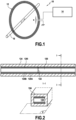
- FIG. 1 illustrates the contactless electric current measuring device 10 according to the invention comprising a flexible sensor 12 preferably of toroidal shape but not only, and an electronic processing module 14 for processing the output signal from the sensor and obtaining via a dedicated microprocessor or a microcontroller the value of the current measured in a conductor 16 surrounded by the flexible sensor 12.
- This measuring device is very close to a Rogowski sensor but with the addition of a magnetic core.
- the addition of the magnetic core allows a gain well above 1000 at very low frequencies which, however, almost disappears at the center of the magnetization curve of the material.
- the object of the invention is in particular to correct this cancellation.
- the flexible sensor 12 comprises a magnetic core 120 made up of fine superimposed ribbons or strips 120A, 120B,..., 120I which gives it its flexibility along the plane P formed by these magnetic ribbons.
- This stack is advantageously formed of several dozen magnetic strips (typically between 50 and 100) each having a few tens of micrometers thick (typically between 20 and 50 microns), the whole forming a part that is easily deformable in the plane P.
- the ribbons are stacked then blocked in a single place 122 (this blocking being obtained by welding, brazing or bonding), for example in the middle as illustrated in figure 2 or at one end.
- This blocking being obtained by welding, brazing or bonding
- the deformation of the magnetic core thus formed is transferred to the two ends when the ribbons are blocked in the center or to the end which remains free in the event of blocking of the other end.
- the ribbons are held together in a flexible insulating sheath 124, advantageously heat-shrinkable, and they are preferably lubricated with oil or grease (the nature of the lubricant depends on the temperature conditions of use), to be able to withstand the deformation of the core during the encirclement of the conductor 16 traversed by the electric current to be measured and which can be difficult to access unless the flexible sensor is appropriately deformed (see for example the figures 3A-3B comparing this deformed configuration with a configuration without any particular encirclement difficulty). Some applications may be incompatible with the presence of lubricant in the sensor. In such cases, the sheath can then be overmolded and have dry sliding properties.
- the material of the ribbons could advantageously be amorphous iron (METGLAS ® ).
- the problem of its closure arises with a minimum air gap of between 1mm and a few mm (typically 1 to 5mm) whose saturation must then be controlled. Indeed, to control the saturation of the material, it is necessary to have an air gap at the closure of the flexible sensor 12 around the conductor 16, the presence of this air gap making it possible to increase the value of the saturation field and therefore to linearize the sensor (however at the cost of reduced sensitivity and an increase in parasitic fields external to the sensor).
- This closure member 126 comprises a magnetic tube 128 with high relative permeability, typically greater than 10,000, such as a ferrite or any other equivalent material, in which the two ends of the magnetic core are fitted together, leaving a non-zero air gap between them.
- the flexible insulating sheath 124 which holds the stack of magnetic ribbons 120 in position is surrounded over its entire length by an electrical winding 130, advantageously with contiguous turns thus forming a solenoid, the two ends of which pass through an external flexible protective sheath 132 to deliver the output measurement signal for the processing unit 14 at the level of a measurement cable 134 (in the example illustrated the measurement winding making a round trip on the sheath the two output ends are found 'the same side of the sheath).
- An external housing 136 ensures the protection of the ferrite while allowing the opening of the measurement loop.
- the processing unit is illustrated in Figure 5 which gives a simplified principle diagram. It comprises a square signal generator 140 whose output is connected to a low-pass filter 142 whose cutoff frequency between the fundamental Fpol and the first harmonic 2Fpol makes it possible to remove the harmonics and obtain a perfect signal at the output. sinusoidal. Alternatively, this signal sinusoidal could also be obtained directly from a quartz or any other oscillating device for example.
- the sinusoidal signal is injected into the electrical winding 130 which delivers the output signal (measurement signal) of the flexible sensor for a filter of determined frequency 144 whose output is connected to a high gain amplifier 146, typically 10000, including zero (its rest point) is shifted by a voltage source 148.
- the amplified signal delivered at the output of the amplifier constitutes the input signal for a microprocessor or microcontroller 150 (or other equivalent component such as ASIC or FPGA for example) which ensures an analog-digital conversion of the amplified signal and its processing to deliver a current value.
- the current value thus determined can be converted into an effective value and displayed on a display 152 (other current parameters such as frequency and the continuous average value can optionally also be displayed).
- this processing unit is powered by a battery (not shown), rechargeable or not, typically 5V, the charge level of which can also be viewed on the display.
- this display can also display a certain number of other states making it possible to check the correct operation of the measuring device.
- the magnetic core 120 described above is surrounded by the electrical measuring winding 130 over its entire length.
- the measuring winding is the seat of an induced electromotive force whose amplitude is proportional to the amplitude of the current and to its frequency.
- the role of the processing unit 14 is to amplify this signal and equalize it in frequency in order to obtain a flat bandwidth in the frequency domain considered.
- the present invention aims to measure very low alternating currents (a few mA) and for such low values, the magnetization curve of the magnetic material (diagram B-H) is not linear.
- the aforementioned Barkhausen jump phenomenon is compensated by the use of magnetic polarization.
- an alternating polarization current of polarization frequency Fpol greater than the upper limit of the useful bandwidth and of amplitude greater than that of the current i to be measured is added in the winding of measurement 130.
- the polarization field thus created means that the magnetic rest point is no longer stationary at the center of the magnetization curve but that it moves permanently at the rate of the polarization current thus created.
- the frequency ratio between the polarization frequency and the measurement frequency is sufficiently high (i.e. greater than 2.5)
- each value of the measurement field goes through one or more magnetization / demagnetization cycles at the polarization frequency Fpol and at an average amplitude corresponding to the amplitude of the polarization current.
- the appropriate frequency filtering 144 (low pass but which could also be band-stop) then eliminates the signal at the polarization frequency Fpol to retain only that of the measurement signal.
- the choice of the cut-off frequency of this filter is an optimization calculation consisting of eliminating the output component at the polarization frequency at the lowest cost.
- an analog filter is used.
- the polarization frequency being chosen beyond the useful bandwidth, there is therefore before filtering a very strong preponderance of the polarization signal relative to the useful signal in a ratio which may be 50,000/1 for example.
- the frequency Fpol not a multiple of the measurement frequency can be between 133 and 333 Hz, typically 166 Hz, and the frequency Fc of the low-pass filter can be between 2 and 30Hz, typically 16Hz.
- the frequency Fpol not a multiple of the measurement frequency can be between 3.1 and 10.1kHz, typically 6.666kHz
- the frequency Fc of the low-pass filter can be included between 2 and 4.5kHz, typically 2.6KHz or the rejection frequency of the notch filter can be between 3.1 and 10.1kHz, typically 6.666kHz.
- the magnetic polarization frequency can be chosen arbitrarily larger than the measurement spectrum and eliminated by low pass filtering. In all cases, we can also use rejection filtering as long as the polarization frequency is not part of this measurement spectrum.
Landscapes
- Engineering & Computer Science (AREA)
- Power Engineering (AREA)
- Physics & Mathematics (AREA)
- General Physics & Mathematics (AREA)
- Measuring Instrument Details And Bridges, And Automatic Balancing Devices (AREA)
Claims (12)
- Vorrichtung (10) zur kontaktlosen Messung von Wechselstrom, die einen flexiblen Sensor (12) und eine Verarbeitungseinheit (14) beinhaltet, wobei der flexible Sensor einen Leiter (16) umgibt, der von einem zu messenden elektrischen Strom mit einer Amplitude von weniger als 10 mA durchflossen wird, und einen verformbaren magnetischen Kern (120) aufweist, wobei in der Vorrichtung die Verarbeitungseinheit dazu ausgestaltet ist, in einer Messspule (130) zu einem zu messenden Strom mit einer Frequenz F einen Vorspannungsstrom mit einer Vorspannungsfrequenz Fpol, die kein Vielfaches und zumindest 2,5 mal höher als diese Frequenz F ist, und mit einer größeren Amplitude als die Amplitude des zu messenden Stroms hinzuzufügen, anschließend mittels eines Filters für eine bestimmte Frequenz (144) diesen Vorspannungsstrom mit der Vorspannungsfrequenz Fpol zu eliminieren, um nur den zu messenden Strom mit der Frequenz F zu erhalten.
- Vorrichtung zur Messung nach Anspruch 1, dadurch gekennzeichnet, dass der Filter für die bestimmte Frequenz (144) ein Tiefpass- oder Bandsperrfilter ist.
- Vorrichtung zur Messung nach Anspruch 2, dadurch gekennzeichnet, dass der Vorspannungsstrom mit der Vorspannungsfrequenz Fpol am Ausgang eines Tiefpassfilters (142) erhalten wird, der am Ausgang eines Rechtecksignal-Generators (140) montiert ist und dessen Grenzfrequenz niedriger ist als die erste Harmonische 2Fpol der Vorspannungsfrequenz.
- Vorrichtung zur Messung nach Anspruch 2, dadurch gekennzeichnet, dass, wenn das Messsignal bei 50/60 Hz liegt, die Frequenz Fpol zwischen 133 und 333 Hz, in der Regel bei 166 Hz, liegt und die Grenzfrequenz Fc des Tiefpassfilters zwischen 2 und 30 Hz, in der Regel bei 16 Hz, liegt.
- Vorrichtung zur Messung nach Anspruch 2, dadurch gekennzeichnet, dass, wenn das Messsignal bei 1 kHz liegt, die Frequenz Fpol zwischen 3,1 und 10,1 kHz, in der Regel bei 6,666 kHz, liegt und die Grenzfrequenz Fc des Tiefpassfilters zwischen 2 und 4,5 kHz, in der Regel bei 2,6 kHz, liegt oder die Sperrfrequenz des Bandsperrfilters zwischen 3,1 und 10,1 kHz, in der Regel bei 6,666 kHz, liegt.
- Vorrichtung zur Messung nach Anspruch 1, dadurch gekennzeichnet, dass die Verarbeitungseinheit dazu ausgestaltet ist, die Vorspannungsfrequenz Fpol so zu berechnen, dass sie permanent kein Vielfaches der Frequenz F ist.
- Vorrichtung zur Messung nach Anspruch 1, dadurch gekennzeichnet, dass der verformbare magnetische Kern aus mehreren zehn magnetischen Streifen (120A - 1201) gebildet wird, die jeweils einige zehn Mikrometer Dicke aufweisen und deren zwei Enden dazu bestimmt sind, in ein magnetisches Rohr (128) eines Verschlussorgans (126) gesteckt zu werden, wobei zwischen ihnen ein Spalt e ungleich null verbleibt.
- Vorrichtung zur Messung nach Anspruch 5, dadurch gekennzeichnet, dass die magnetischen Streifen (120A - 1201) jeweils aus amorphem Eisen gebildet sind.
- Vorrichtung zur Messung nach Anspruch 5, dadurch gekennzeichnet, dass das magnetische Rohr (128) eine starke relative Permeabilität, in der Regel von mehr als 10.000, aufweist.
- Vorrichtung zur Messung nach einem der Ansprüche 5 bis 9, dadurch gekennzeichnet, dass die magnetischen Streifen (120A - 1201) an einem ihrer zwei Enden oder in ihrer Mitte festgesetzt sind.
- Vorrichtung zur Messung nach einem der Ansprüche 5 bis 10, dadurch gekennzeichnet, dass der verformbare magnetische Kern in einer flexiblen, isolierten und geschmierten Hülle (124) montiert ist, um die Verformung des magnetischen Kerns (120) bei der Umschließung des Leiters (16), der von dem zu messenden elektrischen Strom durchflossen wird, zu unterstützen.
- Vorrichtung zur Messung nach Anspruch 11, dadurch gekennzeichnet, dass die flexible Hülle (124) aus einem wärmeschrumpfbaren Material gebildet ist.
Applications Claiming Priority (1)
| Application Number | Priority Date | Filing Date | Title |
|---|---|---|---|
| FR2012196A FR3116608B1 (fr) | 2020-11-26 | 2020-11-26 | Dispositif de mesure de courant électrique sans contact à noyau magnétique flexible |
Publications (2)
| Publication Number | Publication Date |
|---|---|
| EP4009057A1 EP4009057A1 (de) | 2022-06-08 |
| EP4009057B1 true EP4009057B1 (de) | 2024-07-17 |
Family
ID=74860050
Family Applications (1)
| Application Number | Title | Priority Date | Filing Date |
|---|---|---|---|
| EP21210841.9A Active EP4009057B1 (de) | 2020-11-26 | 2021-11-26 | Kontaktlose strommessvorrichtung mit flexiblem magnetkern |
Country Status (3)
| Country | Link |
|---|---|
| EP (1) | EP4009057B1 (de) |
| ES (1) | ES2988378T3 (de) |
| FR (1) | FR3116608B1 (de) |
Families Citing this family (1)
| Publication number | Priority date | Publication date | Assignee | Title |
|---|---|---|---|---|
| KR102828223B1 (ko) * | 2022-11-07 | 2025-07-04 | 효성중공업 주식회사 | 넓은 전류 측정범위와 시스템 선형성을 갖는 차단기용 수동형 저전력변류기 |
Family Cites Families (11)
| Publication number | Priority date | Publication date | Assignee | Title |
|---|---|---|---|---|
| FR2710753B1 (fr) * | 1993-09-27 | 1995-10-27 | Commissariat Energie Atomique | Capteur de courant comprenant un ruban magnétorésistif et son procédé de réalisation. |
| JPH08250351A (ja) * | 1995-03-14 | 1996-09-27 | Tohoku Denki Hoan Kyokai | 変流器 |
| FR2877486B1 (fr) * | 2004-10-29 | 2007-03-30 | Imphy Alloys Sa | Tore nanocristallin pour capteur de courant, compteurs d'energie a simple et a double etage et sondes de courant les incorporant |
| FR2891917B1 (fr) * | 2005-10-07 | 2008-01-11 | Billanco | Capteurs de champ magnetique et de courant, procede de commande et noyau magnetique pour ces capteurs |
| FR2931945B1 (fr) * | 2008-05-22 | 2010-06-18 | Billanco | Capteur de circulation de champ magnetique et capteur de courant mettant en oeuvre un tel capteur |
| FR2953028B1 (fr) * | 2009-11-26 | 2012-04-20 | Billanco | Capteur de circulation de champs magnetiques equipe d'un moyen de verification, et procede de verification d'un tel capteur. |
| FR2983966A1 (fr) * | 2011-12-12 | 2013-06-14 | Univ Orleans | Dispositif pour mesurer un courant electrique |
| FR3060757B1 (fr) * | 2016-12-19 | 2020-11-06 | Safran Electronics & Defense | Capteur de courant a vanne de flux |
| CN207541138U (zh) * | 2017-11-13 | 2018-06-26 | 北京厚德新能电气科技有限公司 | 一种用于变压器绕组变形监测的柔性电流传感器 |
| FR3076657B1 (fr) * | 2018-01-05 | 2021-04-09 | Socomec Sa | Transformateur de courant ouvrant a noyau magnetique souple |
| FR3083321B1 (fr) * | 2018-06-27 | 2021-03-05 | Safran Electronics & Defense | Capteur de courant a vanne de flux |
-
2020
- 2020-11-26 FR FR2012196A patent/FR3116608B1/fr active Active
-
2021
- 2021-11-26 EP EP21210841.9A patent/EP4009057B1/de active Active
- 2021-11-26 ES ES21210841T patent/ES2988378T3/es active Active
Also Published As
| Publication number | Publication date |
|---|---|
| ES2988378T3 (es) | 2024-11-20 |
| EP4009057A1 (de) | 2022-06-08 |
| FR3116608A1 (fr) | 2022-05-27 |
| FR3116608B1 (fr) | 2022-12-23 |
Similar Documents
| Publication | Publication Date | Title |
|---|---|---|
| EP1947469B1 (de) | Vorrichtung zur magnetischen Verstärkung, die mit einem Magnetempfänger mit Längswellensensiblität ausgestattet ist | |
| EP0023180B1 (de) | Interferometrische Vorrichtung zum Messen elektrischen Stromes mit einer Fiberoptik | |
| FR3033647B1 (fr) | Capteur de courant pour mesurer un courant alternatif | |
| US5305075A (en) | Magnetostrictive transducer system having a three dual-strip fiber optic magnetostrictive transducers bonded into a single fiber mach-zehnder interferometer | |
| EP4009057B1 (de) | Kontaktlose strommessvorrichtung mit flexiblem magnetkern | |
| FR3021750A1 (fr) | Dispositif de detection de courant | |
| EP3729107A1 (de) | Vorrichtung zur messung eines elektrischen und / oder magnetischen feldes, insbesondere bei einem leiter zum transport von elektrischer energie | |
| EP2761309A1 (de) | Kontaktloser stromsensor | |
| EP2261684A1 (de) | Integrierter magnetischer 3D Sensor | |
| FR2827962A1 (fr) | Dispositif de mesure a effet hall de l'intensite d'un courant electrique | |
| US20130032730A1 (en) | Aharonov-bohm sensor | |
| EP2525200B1 (de) | Thermoelektrische Komponente mit plasmonischer Führung, die eine Messvorrichtung der gekoppelten Leistung im geführten Modus umfasst | |
| EP0324292A1 (de) | Kontinuierliches Magnetfeldvektormessgerät mit einem kapazitiv-magnetostriktiven Sensor und seine Anwendung in einem Gradientenmessgerät | |
| US11353523B2 (en) | Detection of fields | |
| FR2700846A1 (fr) | Dispositif de mesure de contraintes ou déformations par résonance ferromagnétique, et procédé de mise en Óoeuvre dudit dispositif. | |
| EP0151895B1 (de) | Magneto-optisches Magnetfeldmessungsverfahren, Anordnung und Zelle zum Messen mit solch einem Verfahren | |
| EP3642635B1 (de) | Stromsensor mit magnetfeldzirkulation | |
| FR3105825A1 (fr) | Dispositif de mesure optique d’un paramètre physique | |
| FR2523312A1 (fr) | Dispositif interferometrique de mesure de courant electrique a fibre optique | |
| EP3149506B1 (de) | Antennenadapter | |
| FR2983966A1 (fr) | Dispositif pour mesurer un courant electrique | |
| Suzuki et al. | Short-wavelength infrared light sensing using an electrostatic MEMS resonator integrated with a plasmonic optical absorber | |
| Han et al. | Micro Capacitive Electric-field Sensor Based on Electrostatic Force | |
| EP0696720A1 (de) | Pendelartiger Sensor mit unbeschränkter Drehbewegung um die Rollachse | |
| US9632113B2 (en) | Few-moded fiber for sensing current |
Legal Events
| Date | Code | Title | Description |
|---|---|---|---|
| PUAI | Public reference made under article 153(3) epc to a published international application that has entered the european phase |
Free format text: ORIGINAL CODE: 0009012 |
|
| STAA | Information on the status of an ep patent application or granted ep patent |
Free format text: STATUS: THE APPLICATION HAS BEEN PUBLISHED |
|
| AK | Designated contracting states |
Kind code of ref document: A1 Designated state(s): AL AT BE BG CH CY CZ DE DK EE ES FI FR GB GR HR HU IE IS IT LI LT LU LV MC MK MT NL NO PL PT RO RS SE SI SK SM TR |
|
| STAA | Information on the status of an ep patent application or granted ep patent |
Free format text: STATUS: REQUEST FOR EXAMINATION WAS MADE |
|
| 17P | Request for examination filed |
Effective date: 20220705 |
|
| RBV | Designated contracting states (corrected) |
Designated state(s): AL AT BE BG CH CY CZ DE DK EE ES FI FR GB GR HR HU IE IS IT LI LT LU LV MC MK MT NL NO PL PT RO RS SE SI SK SM TR |
|
| GRAP | Despatch of communication of intention to grant a patent |
Free format text: ORIGINAL CODE: EPIDOSNIGR1 |
|
| STAA | Information on the status of an ep patent application or granted ep patent |
Free format text: STATUS: GRANT OF PATENT IS INTENDED |
|
| INTG | Intention to grant announced |
Effective date: 20240410 |
|
| P01 | Opt-out of the competence of the unified patent court (upc) registered |
Effective date: 20240402 |
|
| GRAS | Grant fee paid |
Free format text: ORIGINAL CODE: EPIDOSNIGR3 |
|
| GRAA | (expected) grant |
Free format text: ORIGINAL CODE: 0009210 |
|
| STAA | Information on the status of an ep patent application or granted ep patent |
Free format text: STATUS: THE PATENT HAS BEEN GRANTED |
|
| AK | Designated contracting states |
Kind code of ref document: B1 Designated state(s): AL AT BE BG CH CY CZ DE DK EE ES FI FR GB GR HR HU IE IS IT LI LT LU LV MC MK MT NL NO PL PT RO RS SE SI SK SM TR |
|
| REG | Reference to a national code |
Ref country code: CH Ref legal event code: EP |
|
| REG | Reference to a national code |
Ref country code: DE Ref legal event code: R096 Ref document number: 602021015773 Country of ref document: DE |
|
| REG | Reference to a national code |
Ref country code: IE Ref legal event code: FG4D Free format text: LANGUAGE OF EP DOCUMENT: FRENCH |
|
| REG | Reference to a national code |
Ref country code: SE Ref legal event code: TRGR |
|
| REG | Reference to a national code |
Ref country code: LT Ref legal event code: MG9D |
|
| REG | Reference to a national code |
Ref country code: NL Ref legal event code: MP Effective date: 20240717 Ref country code: ES Ref legal event code: FG2A Ref document number: 2988378 Country of ref document: ES Kind code of ref document: T3 Effective date: 20241120 |
|
| PG25 | Lapsed in a contracting state [announced via postgrant information from national office to epo] |
Ref country code: PT Free format text: LAPSE BECAUSE OF FAILURE TO SUBMIT A TRANSLATION OF THE DESCRIPTION OR TO PAY THE FEE WITHIN THE PRESCRIBED TIME-LIMIT Effective date: 20241118 |
|
| PG25 | Lapsed in a contracting state [announced via postgrant information from national office to epo] |
Ref country code: NL Free format text: LAPSE BECAUSE OF FAILURE TO SUBMIT A TRANSLATION OF THE DESCRIPTION OR TO PAY THE FEE WITHIN THE PRESCRIBED TIME-LIMIT Effective date: 20240717 |
|
| PG25 | Lapsed in a contracting state [announced via postgrant information from national office to epo] |
Ref country code: PT Free format text: LAPSE BECAUSE OF FAILURE TO SUBMIT A TRANSLATION OF THE DESCRIPTION OR TO PAY THE FEE WITHIN THE PRESCRIBED TIME-LIMIT Effective date: 20241118 Ref country code: NL Free format text: LAPSE BECAUSE OF FAILURE TO SUBMIT A TRANSLATION OF THE DESCRIPTION OR TO PAY THE FEE WITHIN THE PRESCRIBED TIME-LIMIT Effective date: 20240717 |
|
| PG25 | Lapsed in a contracting state [announced via postgrant information from national office to epo] |
Ref country code: NO Free format text: LAPSE BECAUSE OF FAILURE TO SUBMIT A TRANSLATION OF THE DESCRIPTION OR TO PAY THE FEE WITHIN THE PRESCRIBED TIME-LIMIT Effective date: 20241017 |
|
| REG | Reference to a national code |
Ref country code: AT Ref legal event code: UEP Ref document number: 1704616 Country of ref document: AT Kind code of ref document: T Effective date: 20240717 |
|
| PG25 | Lapsed in a contracting state [announced via postgrant information from national office to epo] |
Ref country code: GR Free format text: LAPSE BECAUSE OF FAILURE TO SUBMIT A TRANSLATION OF THE DESCRIPTION OR TO PAY THE FEE WITHIN THE PRESCRIBED TIME-LIMIT Effective date: 20241018 Ref country code: PL Free format text: LAPSE BECAUSE OF FAILURE TO SUBMIT A TRANSLATION OF THE DESCRIPTION OR TO PAY THE FEE WITHIN THE PRESCRIBED TIME-LIMIT Effective date: 20240717 Ref country code: FI Free format text: LAPSE BECAUSE OF FAILURE TO SUBMIT A TRANSLATION OF THE DESCRIPTION OR TO PAY THE FEE WITHIN THE PRESCRIBED TIME-LIMIT Effective date: 20240717 |
|
| PG25 | Lapsed in a contracting state [announced via postgrant information from national office to epo] |
Ref country code: BG Free format text: LAPSE BECAUSE OF FAILURE TO SUBMIT A TRANSLATION OF THE DESCRIPTION OR TO PAY THE FEE WITHIN THE PRESCRIBED TIME-LIMIT Effective date: 20240717 |
|
| PG25 | Lapsed in a contracting state [announced via postgrant information from national office to epo] |
Ref country code: LV Free format text: LAPSE BECAUSE OF FAILURE TO SUBMIT A TRANSLATION OF THE DESCRIPTION OR TO PAY THE FEE WITHIN THE PRESCRIBED TIME-LIMIT Effective date: 20240717 |
|
| PG25 | Lapsed in a contracting state [announced via postgrant information from national office to epo] |
Ref country code: IS Free format text: LAPSE BECAUSE OF FAILURE TO SUBMIT A TRANSLATION OF THE DESCRIPTION OR TO PAY THE FEE WITHIN THE PRESCRIBED TIME-LIMIT Effective date: 20241117 |
|
| PG25 | Lapsed in a contracting state [announced via postgrant information from national office to epo] |
Ref country code: HR Free format text: LAPSE BECAUSE OF FAILURE TO SUBMIT A TRANSLATION OF THE DESCRIPTION OR TO PAY THE FEE WITHIN THE PRESCRIBED TIME-LIMIT Effective date: 20240717 |
|
| PG25 | Lapsed in a contracting state [announced via postgrant information from national office to epo] |
Ref country code: RS Free format text: LAPSE BECAUSE OF FAILURE TO SUBMIT A TRANSLATION OF THE DESCRIPTION OR TO PAY THE FEE WITHIN THE PRESCRIBED TIME-LIMIT Effective date: 20241017 |
|
| PG25 | Lapsed in a contracting state [announced via postgrant information from national office to epo] |
Ref country code: RS Free format text: LAPSE BECAUSE OF FAILURE TO SUBMIT A TRANSLATION OF THE DESCRIPTION OR TO PAY THE FEE WITHIN THE PRESCRIBED TIME-LIMIT Effective date: 20241017 Ref country code: PL Free format text: LAPSE BECAUSE OF FAILURE TO SUBMIT A TRANSLATION OF THE DESCRIPTION OR TO PAY THE FEE WITHIN THE PRESCRIBED TIME-LIMIT Effective date: 20240717 Ref country code: NO Free format text: LAPSE BECAUSE OF FAILURE TO SUBMIT A TRANSLATION OF THE DESCRIPTION OR TO PAY THE FEE WITHIN THE PRESCRIBED TIME-LIMIT Effective date: 20241017 Ref country code: LV Free format text: LAPSE BECAUSE OF FAILURE TO SUBMIT A TRANSLATION OF THE DESCRIPTION OR TO PAY THE FEE WITHIN THE PRESCRIBED TIME-LIMIT Effective date: 20240717 Ref country code: IS Free format text: LAPSE BECAUSE OF FAILURE TO SUBMIT A TRANSLATION OF THE DESCRIPTION OR TO PAY THE FEE WITHIN THE PRESCRIBED TIME-LIMIT Effective date: 20241117 Ref country code: HR Free format text: LAPSE BECAUSE OF FAILURE TO SUBMIT A TRANSLATION OF THE DESCRIPTION OR TO PAY THE FEE WITHIN THE PRESCRIBED TIME-LIMIT Effective date: 20240717 Ref country code: GR Free format text: LAPSE BECAUSE OF FAILURE TO SUBMIT A TRANSLATION OF THE DESCRIPTION OR TO PAY THE FEE WITHIN THE PRESCRIBED TIME-LIMIT Effective date: 20241018 Ref country code: FI Free format text: LAPSE BECAUSE OF FAILURE TO SUBMIT A TRANSLATION OF THE DESCRIPTION OR TO PAY THE FEE WITHIN THE PRESCRIBED TIME-LIMIT Effective date: 20240717 Ref country code: BG Free format text: LAPSE BECAUSE OF FAILURE TO SUBMIT A TRANSLATION OF THE DESCRIPTION OR TO PAY THE FEE WITHIN THE PRESCRIBED TIME-LIMIT Effective date: 20240717 |
|
| PG25 | Lapsed in a contracting state [announced via postgrant information from national office to epo] |
Ref country code: SM Free format text: LAPSE BECAUSE OF FAILURE TO SUBMIT A TRANSLATION OF THE DESCRIPTION OR TO PAY THE FEE WITHIN THE PRESCRIBED TIME-LIMIT Effective date: 20240717 Ref country code: RO Free format text: LAPSE BECAUSE OF FAILURE TO SUBMIT A TRANSLATION OF THE DESCRIPTION OR TO PAY THE FEE WITHIN THE PRESCRIBED TIME-LIMIT Effective date: 20240717 Ref country code: DK Free format text: LAPSE BECAUSE OF FAILURE TO SUBMIT A TRANSLATION OF THE DESCRIPTION OR TO PAY THE FEE WITHIN THE PRESCRIBED TIME-LIMIT Effective date: 20240717 |
|
| REG | Reference to a national code |
Ref country code: DE Ref legal event code: R097 Ref document number: 602021015773 Country of ref document: DE |
|
| PG25 | Lapsed in a contracting state [announced via postgrant information from national office to epo] |
Ref country code: EE Free format text: LAPSE BECAUSE OF FAILURE TO SUBMIT A TRANSLATION OF THE DESCRIPTION OR TO PAY THE FEE WITHIN THE PRESCRIBED TIME-LIMIT Effective date: 20240717 |
|
| PG25 | Lapsed in a contracting state [announced via postgrant information from national office to epo] |
Ref country code: CZ Free format text: LAPSE BECAUSE OF FAILURE TO SUBMIT A TRANSLATION OF THE DESCRIPTION OR TO PAY THE FEE WITHIN THE PRESCRIBED TIME-LIMIT Effective date: 20240717 |
|
| PG25 | Lapsed in a contracting state [announced via postgrant information from national office to epo] |
Ref country code: SK Free format text: LAPSE BECAUSE OF FAILURE TO SUBMIT A TRANSLATION OF THE DESCRIPTION OR TO PAY THE FEE WITHIN THE PRESCRIBED TIME-LIMIT Effective date: 20240717 |
|
| PLBE | No opposition filed within time limit |
Free format text: ORIGINAL CODE: 0009261 |
|
| STAA | Information on the status of an ep patent application or granted ep patent |
Free format text: STATUS: NO OPPOSITION FILED WITHIN TIME LIMIT |
|
| 26N | No opposition filed |
Effective date: 20250422 |
|
| PG25 | Lapsed in a contracting state [announced via postgrant information from national office to epo] |
Ref country code: MC Free format text: LAPSE BECAUSE OF FAILURE TO SUBMIT A TRANSLATION OF THE DESCRIPTION OR TO PAY THE FEE WITHIN THE PRESCRIBED TIME-LIMIT Effective date: 20240717 |
|
| PG25 | Lapsed in a contracting state [announced via postgrant information from national office to epo] |
Ref country code: LU Free format text: LAPSE BECAUSE OF NON-PAYMENT OF DUE FEES Effective date: 20241126 |
|
| REG | Reference to a national code |
Ref country code: BE Ref legal event code: MM Effective date: 20241130 |
|
| PG25 | Lapsed in a contracting state [announced via postgrant information from national office to epo] |
Ref country code: BE Free format text: LAPSE BECAUSE OF NON-PAYMENT OF DUE FEES Effective date: 20241130 |
|
| PGFP | Annual fee paid to national office [announced via postgrant information from national office to epo] |
Ref country code: FR Payment date: 20250901 Year of fee payment: 5 |
|
| PG25 | Lapsed in a contracting state [announced via postgrant information from national office to epo] |
Ref country code: IE Free format text: LAPSE BECAUSE OF NON-PAYMENT OF DUE FEES Effective date: 20241126 |
|
| REG | Reference to a national code |
Ref country code: CH Ref legal event code: U11 Free format text: ST27 STATUS EVENT CODE: U-0-0-U10-U11 (AS PROVIDED BY THE NATIONAL OFFICE) Effective date: 20251201 |
|
| PGFP | Annual fee paid to national office [announced via postgrant information from national office to epo] |
Ref country code: DE Payment date: 20251117 Year of fee payment: 5 |
|
| PGFP | Annual fee paid to national office [announced via postgrant information from national office to epo] |
Ref country code: GB Payment date: 20251126 Year of fee payment: 5 |
|
| PGFP | Annual fee paid to national office [announced via postgrant information from national office to epo] |
Ref country code: AT Payment date: 20260113 Year of fee payment: 5 |
|
| PGFP | Annual fee paid to national office [announced via postgrant information from national office to epo] |
Ref country code: IT Payment date: 20251107 Year of fee payment: 5 |
|
| PG25 | Lapsed in a contracting state [announced via postgrant information from national office to epo] |
Ref country code: IT Free format text: LAPSE BECAUSE OF NON-PAYMENT OF DUE FEES Effective date: 20241126 |
|
| PGFP | Annual fee paid to national office [announced via postgrant information from national office to epo] |
Ref country code: SE Payment date: 20251121 Year of fee payment: 5 Ref country code: CH Payment date: 20251201 Year of fee payment: 5 |
|
| PGFP | Annual fee paid to national office [announced via postgrant information from national office to epo] |
Ref country code: ES Payment date: 20251210 Year of fee payment: 5 |
|
| PG25 | Lapsed in a contracting state [announced via postgrant information from national office to epo] |
Ref country code: HU Free format text: LAPSE BECAUSE OF FAILURE TO SUBMIT A TRANSLATION OF THE DESCRIPTION OR TO PAY THE FEE WITHIN THE PRESCRIBED TIME-LIMIT; INVALID AB INITIO Effective date: 20211126 |
|
| PG25 | Lapsed in a contracting state [announced via postgrant information from national office to epo] |
Ref country code: CY Free format text: LAPSE BECAUSE OF FAILURE TO SUBMIT A TRANSLATION OF THE DESCRIPTION OR TO PAY THE FEE WITHIN THE PRESCRIBED TIME-LIMIT; INVALID AB INITIO Effective date: 20211126 |
|
| PG25 | Lapsed in a contracting state [announced via postgrant information from national office to epo] |
Ref country code: IT Free format text: LAPSE BECAUSE OF NON-PAYMENT OF DUE FEES Effective date: 20241126 |
|
| PGRI | Patent reinstated in contracting state [announced from national office to epo] |
Ref country code: IT Effective date: 20241130 |