EP4009070B1 - Verfahren und system zur hinderniserkennung mithilfe eines hindernissensors für luftfahrzeug - Google Patents
Verfahren und system zur hinderniserkennung mithilfe eines hindernissensors für luftfahrzeug Download PDFInfo
- Publication number
- EP4009070B1 EP4009070B1 EP21206292.1A EP21206292A EP4009070B1 EP 4009070 B1 EP4009070 B1 EP 4009070B1 EP 21206292 A EP21206292 A EP 21206292A EP 4009070 B1 EP4009070 B1 EP 4009070B1
- Authority
- EP
- European Patent Office
- Prior art keywords
- obstacle
- aircraft
- point
- plane
- display
- Prior art date
- Legal status (The legal status is an assumption and is not a legal conclusion. Google has not performed a legal analysis and makes no representation as to the accuracy of the status listed.)
- Active
Links
Images


Classifications
-
- G—PHYSICS
- G01—MEASURING; TESTING
- G01S—RADIO DIRECTION-FINDING; RADIO NAVIGATION; DETERMINING DISTANCE OR VELOCITY BY USE OF RADIO WAVES; LOCATING OR PRESENCE-DETECTING BY USE OF THE REFLECTION OR RERADIATION OF RADIO WAVES; ANALOGOUS ARRANGEMENTS USING OTHER WAVES
- G01S17/00—Systems using the reflection or reradiation of electromagnetic waves other than radio waves, e.g. lidar systems
- G01S17/88—Lidar systems specially adapted for specific applications
- G01S17/93—Lidar systems specially adapted for specific applications for anti-collision purposes
- G01S17/933—Lidar systems specially adapted for specific applications for anti-collision purposes of aircraft or spacecraft
-
- B—PERFORMING OPERATIONS; TRANSPORTING
- B64—AIRCRAFT; AVIATION; COSMONAUTICS
- B64D—EQUIPMENT FOR FITTING IN OR TO AIRCRAFT; FLIGHT SUITS; PARACHUTES; ARRANGEMENT OR MOUNTING OF POWER PLANTS OR PROPULSION TRANSMISSIONS IN AIRCRAFT
- B64D43/00—Arrangements or adaptations of instruments
-
- G—PHYSICS
- G01—MEASURING; TESTING
- G01S—RADIO DIRECTION-FINDING; RADIO NAVIGATION; DETERMINING DISTANCE OR VELOCITY BY USE OF RADIO WAVES; LOCATING OR PRESENCE-DETECTING BY USE OF THE REFLECTION OR RERADIATION OF RADIO WAVES; ANALOGOUS ARRANGEMENTS USING OTHER WAVES
- G01S13/00—Systems using the reflection or reradiation of radio waves, e.g. radar systems; Analogous systems using reflection or reradiation of waves whose nature or wavelength is irrelevant or unspecified
- G01S13/88—Radar or analogous systems specially adapted for specific applications
- G01S13/93—Radar or analogous systems specially adapted for specific applications for anti-collision purposes
- G01S13/933—Radar or analogous systems specially adapted for specific applications for anti-collision purposes of aircraft or spacecraft
-
- G—PHYSICS
- G01—MEASURING; TESTING
- G01S—RADIO DIRECTION-FINDING; RADIO NAVIGATION; DETERMINING DISTANCE OR VELOCITY BY USE OF RADIO WAVES; LOCATING OR PRESENCE-DETECTING BY USE OF THE REFLECTION OR RERADIATION OF RADIO WAVES; ANALOGOUS ARRANGEMENTS USING OTHER WAVES
- G01S7/00—Details of systems according to groups G01S13/00, G01S15/00, G01S17/00
- G01S7/02—Details of systems according to groups G01S13/00, G01S15/00, G01S17/00 of systems according to group G01S13/00
- G01S7/04—Display arrangements
- G01S7/06—Cathode-ray tube displays or other two dimensional or three-dimensional displays
- G01S7/062—Cathode-ray tube displays or other two dimensional or three-dimensional displays in which different colours are used
-
- G—PHYSICS
- G01—MEASURING; TESTING
- G01S—RADIO DIRECTION-FINDING; RADIO NAVIGATION; DETERMINING DISTANCE OR VELOCITY BY USE OF RADIO WAVES; LOCATING OR PRESENCE-DETECTING BY USE OF THE REFLECTION OR RERADIATION OF RADIO WAVES; ANALOGOUS ARRANGEMENTS USING OTHER WAVES
- G01S7/00—Details of systems according to groups G01S13/00, G01S15/00, G01S17/00
- G01S7/02—Details of systems according to groups G01S13/00, G01S15/00, G01S17/00 of systems according to group G01S13/00
- G01S7/04—Display arrangements
- G01S7/06—Cathode-ray tube displays or other two dimensional or three-dimensional displays
- G01S7/10—Providing two-dimensional [2D] co-ordinated display of distance and direction
- G01S7/12—Plan-position indicators, i.e. P.P.I.
-
- G—PHYSICS
- G01—MEASURING; TESTING
- G01S—RADIO DIRECTION-FINDING; RADIO NAVIGATION; DETERMINING DISTANCE OR VELOCITY BY USE OF RADIO WAVES; LOCATING OR PRESENCE-DETECTING BY USE OF THE REFLECTION OR RERADIATION OF RADIO WAVES; ANALOGOUS ARRANGEMENTS USING OTHER WAVES
- G01S7/00—Details of systems according to groups G01S13/00, G01S15/00, G01S17/00
- G01S7/48—Details of systems according to groups G01S13/00, G01S15/00, G01S17/00 of systems according to group G01S17/00
- G01S7/51—Display arrangements
-
- G—PHYSICS
- G08—SIGNALLING
- G08G—TRAFFIC CONTROL SYSTEMS
- G08G5/00—Traffic control systems for aircraft
- G08G5/20—Arrangements for acquiring, generating, sharing or displaying traffic information
- G08G5/21—Arrangements for acquiring, generating, sharing or displaying traffic information located onboard the aircraft
-
- G—PHYSICS
- G08—SIGNALLING
- G08G—TRAFFIC CONTROL SYSTEMS
- G08G5/00—Traffic control systems for aircraft
- G08G5/50—Navigation or guidance aids
- G08G5/53—Navigation or guidance aids for cruising
-
- G—PHYSICS
- G08—SIGNALLING
- G08G—TRAFFIC CONTROL SYSTEMS
- G08G5/00—Traffic control systems for aircraft
- G08G5/80—Anti-collision systems
-
- G—PHYSICS
- G08—SIGNALLING
- G08G—TRAFFIC CONTROL SYSTEMS
- G08G5/00—Traffic control systems for aircraft
- G08G5/50—Navigation or guidance aids
- G08G5/55—Navigation or guidance aids for a single aircraft
Definitions
- the present invention relates to a method and system for detecting obstacles with an obstacle sensor for an aircraft.
- An aircraft may include an obstacle detection system.
- Such an obstacle detection system may include an obstacle sensor and a display highlighting detected obstacles.
- the obstacle sensor may include an obstacle sensor of the type known by the acronym LIDAR and the English expression "Llght Détection And Ranging".
- a LIDAR obstacle sensor can scan the surrounding space in elevation in an angular field and in azimuth.
- Each detected point of an obstacle can be identified by its position relative to the obstacle sensor. Such a point can be referred to as an "obstacle point" for convenience.
- each obstacle point can be identified by the distance separating it from the obstacle sensor as well as by a bearing angle and a site angle relative to the obstacle sensor.
- An obstacle detection system can include a satellite location device and a memory for locating the obstacle points in a local reference frame of the aircraft.
- Older generation LIDAR obstacle sensors can scan the surrounding space only over 120 degrees in azimuth, in a restricted angular field in elevation of plus or minus 3 degrees, and over a restricted distance of less than 100 meters.
- an obstacle detection system may include several obstacle sensors to scan the space around an aircraft cell, which can have an impact on the mass of the aircraft.
- the beam of the LIDAR obstacle sensor may no longer come into contact with a obstacle located near the aircraft.
- this scanned angular field can pass over a nearby pylon. The pylon is then not detected.
- LIDAR obstacle sensors are more efficient.
- a modern LIDAR obstacle sensor can detect obstacles at a distance of about 200 meters, vertically in an angular field of plus or minus 22.5 degrees relative to a median position, and in azimuth at 360 degrees around the aircraft.
- LIDAR obstacle sensor can for example acquire about 3 million obstacle points per second.
- Such a high-performance LIDAR obstacle sensor may be interesting, for example to use a single obstacle sensor instead of a system having several less high-performance obstacle sensors.
- a high-performance LIDAR obstacle sensor may surprisingly prove problematic by detecting a very large number of points belonging to obstacles, in particular near the relief.
- the high-performance LIDAR obstacle sensor may detect points belonging to obstacles that do not present a real danger in the short term. Consequently, the obstacle detection system may have difficulty in quickly processing all of the obstacle points detected.
- the display of the obstacle detection system may in fact display a representation of many obstacle points. By scanning a display displaying many obstacle points, a pilot may then have difficulty in objectively and quickly analyzing the data displayed, in parallel with the other tasks to be accomplished.
- the document EP3236213 describes a display system receiving data from a plurality of sensors to display a three-dimensional illustration of a region surrounding an aircraft: Each hazard is displayed in a color corresponding to its priority.
- the document EP3236213 mentions the possibility of adjusting the power of the sensors.
- the document EP3163318 describes an obstacle detection system that has a display and a processor.
- the processor receives data from sensors that are configured to detect obstacles around the aircraft.
- the processor generates display data by sector and for a plurality of blocks within the sectors.
- the document US2013/0332062 A1 describes an obstacle detection system that is equipped with a display and a processor.
- the present invention therefore aims to propose a method for detecting obstacles which is efficient and makes the measured data intelligible.
- the invention thus aims at a method for detecting obstacles in the vicinity of an aircraft.
- This method comprises the steps of claim 1.
- the method allows the use of an obstacle sensor comprising, for example, a modern and efficient LIDAR.
- an obstacle sensor comprising, for example, a modern and efficient LIDAR.
- the performance of such a LIDAR can be a source of difficulties.
- Positioning data is obtained in a conventional manner and includes, for example, a distance, elevation angle and/or bearing angle relative to the aircraft.
- the term "surrounding space” refers to the space scanned by the obstacle sensor.
- obstacle point refers to a point on an obstacle detected by the obstacle sensor.
- each obstacle point located within said detection volume being a relevant point
- each point detected by the obstacle sensor which is in the surrounding space and at the same time in the detection volume is a relevant point.
- the obstacle points located outside this detection volume are said for convenience and opposition to be “non-relevant points”.
- obstacle points are filtered to display relevant points. Irrelevant points are not displayed on the display.
- a tree or the ground may be located in the field scanned by the obstacle sensor while the aircraft is located well above the ground or this tree.
- the ground or for example, this tree does not pose an immediate danger and is not within the detection volume. Therefore, obstacle points on the ground or this tree will be irrelevant.
- the ground or tree will be eliminated from the display given to the pilot.
- the method makes it possible to filter the measurements of the obstacle sensor, in order to only use, during a display step, the measurements relating to objects likely to represent a real danger, these objects being present in the predetermined detection volume corresponding to a safety and surveillance volume around the aircraft.
- the method can be applied using an extremely simple and in fact reliable and easily certifiable filter, unlike complex processing systems aimed for example at identifying particular objects in a point cloud.
- the method may further comprise one or more of the following features, taken alone or in combination.
- the surrounding space scanned by the obstacle sensor comprises a scanned volume which can extend 360 degrees around an axis of symmetry attached to the aircraft, said surrounding space extending in elevation in an angular field extending on either side of a median plane orthogonal to said axis of symmetry.
- the obstacle sensor can thus scan a substantially annular space that surrounds the aircraft and has a symmetry with respect to the axis of symmetry.
- the obstacle sensor can comprise a single obstacle sensor, for example of the LIDAR type.
- the axis of symmetry can then pass through this sensor. obstacles.
- the obstacle sensor can be movable in rotation around the axis of symmetry.
- the space scanned can correspond at any time to the volume scanned, up to the scanning frequency of the obstacle sensor.
- the space scanned can include each scanned volume analyzed since a measurement time, namely calculated or predefined or even memorized.
- a detector of the obstacle sensor can apply an algorithm upstream of the filter to store the measurements made by the obstacle sensor(s) over a period called "measurement time" for convenience.
- Said algorithm can aggregate the measurements, the scanned space resulting from the aggregation of all the volumes scanned during this period and repositioned in coherence with respect to each other in a single reference frame.
- the result of this aggregation has the advantage of covering a much denser and more extensive scanned space than that which the obstacle sensor can acquire at a given time.
- the filter which makes it possible to eliminate the detections which do not present a real danger is therefore even more decisive on the result which will be presented.
- the measurement time can be at least 2 minutes or can even correspond to the time elapsed since the aircraft was switched on, take-off, i.e. the moment when the landing gear(s) left the ground, reaching a particular point in a take-off procedure, etc.
- the space being scanned includes all the volumes scanned over the last two minutes. From then on, said algorithm memorizes and repositions between them all the detections obtained over the last two minutes, then the obstacle points detected are transmitted to the filter which only retains the relevant points presenting a real danger for display.
- the combination of this type of algorithm with the filter can allow at a given time to consider an obstacle that does not enter the volume scanned by the obstacle sensor at this given time.
- an aircraft can perform a forward flight and the measurement time can be two minutes.
- the measurement time can be two minutes.
- an obstacle located under the aircraft is not detectable by the obstacle sensor.
- one minute previously this obstacle was located in front of the aircraft and could have been detected by the obstacle sensor.
- the obstacle points corresponding to this obstacle are then still processed by the filter and are analyzed to be classified as being relevant or non-relevant points.
- the measurement time considered may be a constant or may vary depending on the aircraft's speed of movement.
- the measurement time considered may be calculated using a linear function giving the measurement time as a function of the inverse of the speed of movement of the aircraft. Consequently, if the position of the aircraft is quasi-stationary, this definition of the measurement time implies that the system will display relevant obstacle points even if they have not been in the sensor's scanning field for a duration close to the duration of the quasi-stationary flight.
- said angular field can present an angle of at least 40 degrees.
- the obstacle sensor may include a so-called “wide-angle” LIDAR obstacle sensor.
- said display can comprise a step of displaying, according to a two-dimensional representation, said relevant points seen from above or below the aircraft, favorably seen from above, and at 360 degrees around a symbol representing the aircraft.
- the obstacle sensor can detect a very large number of obstacle points per second, for example of the order of several million obstacle points. Such a density of obstacle points can make it possible to develop a three-dimensional representation of the aircraft's environment. The preceding characteristic goes against the prejudice of thinking that such a representation is optimal. Indeed, a three-dimensional representation is dependent on the visual interpretation made by the pilot. During a flight phase requiring a significant workload, a pilot may have difficulty in effectively and quickly understanding his position and perceiving the distance separating him from the obstacles by consulting such a display.
- the previous feature proposes a simpler display representing, in a top or bottom view and in two dimensions, the relevant points around a symbol representing the aircraft.
- a display in synergy with a relevant filtering of the obstacle points can allow the crew to quickly understand the direction and distance of the dangerous obstacles surrounding the aircraft.
- said detection volume can be attached to the aircraft, said detection volume defining a volume in which an obstacle is likely to present a danger for the aircraft.
- this origin point can be a position of an obstacle sensor of the obstacle sensor.
- this origin point can be the center of gravity of a LIDAR.
- the detection volume moves in conjunction with the movement of the aircraft.
- the detection volume extends above a low plane, and advantageously between an included high plane and an included low plane, the high plane and the low plane being located vertically, namely along a vertical axis, respectively above and below the aircraft.
- the high plane and the low plane delimit in elevation a strip of airspace in which both the aircraft and the obstacles likely to be dangerous are located.
- the top plane and the bottom plane can be parallel.
- the aircraft may be a rotorcraft comprising an airframe extending upwards from one or more landing gears to a rotor.
- the positions of the upper plane and the lower plane are then, for example, determined with respect to any obstacle that could collide with the rotor or with the landing gear(s).
- the method comprises a step of determining a maximum threshold height and a minimum threshold height.
- Said threshold height maximum threshold is a distance separating said high plane and a reference of the aircraft along the vertical, said minimum threshold height being a distance separating said reference and said low plane along the vertical.
- This technical feature has the effect of positioning the low plane and the high plane adequately to identify relevant points that are actually dangerous.
- the high plane and the low plane are positioned relative to an aircraft reference by determining a maximum threshold height and a minimum threshold height.
- the maximum threshold height and/or the minimum threshold height may be stored or calculated.
- this reference may be a position of an obstacle sensor of the obstacle sensor.
- the reference may be the center of gravity of a LIDAR.
- the obstacle sensor's obstacle sensor as a reference can have the advantage of facilitating the positioning of the obstacle points measured relative to the high plane and the low plane. Indeed, the obstacle points can be relatively easily positioned relative to this obstacle sensor.
- the method may in particular comprise a determination of an obstacle height of each obstacle point relative to a reference plane passing through said reference, each relevant point having relative to the reference plane an obstacle height placing it between the high plane and the low plane.
- the reference plane may be parallel to the high plane and/or to the low plane.
- the obstacle height can be the shortest distance between the reference plane and the obstacle point of interest.
- each obstacle height is by convention positive for any object placed above the reference plane and negative for any object located below the reference plane, the terms above and below being considered in terrestrial reference, and for example in the view of an observer present on the ground.
- the minimum threshold height is negative and the maximum threshold height is positive.
- a relevant point has an obstacle height included for example and according to the variant between the minimum threshold height included and the maximum threshold height included.
- the obstacle height of a said obstacle point can be a function of the distance of the obstacle point relative to the reference as well as a site angle of said obstacle point relative to the reference and a bearing angle of the obstacle point relative to the reference.
- Each obstacle point can then be characterized by a distance Dn between 0 and the maximum detection distance of the obstacle sensor, a site angle for example between -25 degrees and +25 degrees relative to a median plane corresponding to the middle of the scanned field, and a bearing angle between 0 degrees and 360 degrees with for example the bearing angle of 0 degrees corresponding to the position of a nose of the aircraft and the bearing angle of 180 degrees corresponding to the tail of the aircraft.
- a roll angle and pitch angle of the aircraft measured in a conventional manner can also be taken into account to dynamically maintain the detection volume relative to the terrestrial environment.
- Hn represents the obstacle height
- "*” represents the multiplication sign
- "+” represents the addition sign
- "sin” represents the sine function
- "cos” represents the cosine function
- "Dn” represents the distance of the obstacle point from the reference obtained using the obstacle sensor
- "alphan” represents the elevation angle of the obstacle point obtained using the obstacle sensor
- psin represents the bearing angle of the obstacle point obtained using the obstacle sensor
- phi represents the roll angle of the aircraft
- theta represents the pitch angle of the aircraft.
- said maximum threshold height can be equal in absolute value to the distance separating a top of the aircraft from the reference plus a first safety margin upwards
- said minimum threshold height is equal in absolute value to a distance from one end of a landing gear from the reference plus a second safety margin downwards.
- said maximum threshold height and said minimum threshold height are variable as a function of at least one of the following parameters: a vertical speed of the aircraft, a height of the aircraft relative to the ground, a forward speed of the aircraft.
- the first margin and the second margin can for example be variable depending on this vertical speed and/or a height above the ground and/or a forward speed, namely an air speed or an equivalent.
- the first margin and the second margin may decrease when the vertical speed decreases.
- said upper plane and said lower plane are horizontal.
- said high plane and said low plane are parallel to a face of a landing area.
- the system comprises an adjustment interface for setting an inclination of such a face, and for example of the reference plane previously mentioned.
- the low and high planes are then made parallel to this face of the landing area by offsetting them from the reference plane respectively by the minimum threshold height and the maximum threshold height for example.
- said upper plane and the lower plane are parallel to a plane defined by a longitudinal speed vector and a lateral speed vector of the aircraft.
- the variants may be cumulative, with an individual being able to choose one of the variants using a choice interface for example.
- the variant to be used is chosen automatically by a filter depending on the phase of flight, for example using the third variant above a predetermined airspeed, the first variant below this predetermined airspeed and above a predetermined height and then the second variant below this predetermined airspeed and below the predetermined height.
- the method can include a step of recording said obstacle points in a buffer memory.
- Obstacle points can be stored in a memory for the duration of the mission for example.
- the method can include a step of coloring each relevant point according to the nature of the material of an obstacle detected at this relevant point, this nature being able to be from the group of minerals or the group of metals or the group of organic materials or the group of elements diffuse in the air.
- a LIDAR obstacle sensor can be used to characterize the nature of illuminated objects in a usual manner based on the return of the wave train.
- the display can, for example, use a first color to represent a mineral element (soil, stone, etc.), a second color to represent a metallic element (cable, pylon, etc.), a third color to represent an organic element (foliage, branch, etc.) and a fourth color to represent a diffuse element (cloud, dust, rain, etc.).
- the invention relates to an aircraft equipped with an obstacle detection system, said obstacle detection system comprising an obstacle sensor and a display.
- the obstacle detection system may implement the method of the invention, said obstacle detection system having a filter configured to determine among said obstacle points each relevant point located within a predetermined detection volume, the detection volume being different said surrounding space, said display being configured to display said relevant points.
- the obstacle sensor may comprise one or more obstacle sensors returning distance information, for example of the LIDAR type.
- the obstacle sensor may comprise a detector, for example a calculator, for aggregating the measurements made by the obstacle sensor(s) and transmitting them to the filter.
- said display may be a two-dimensional display.
- said aircraft may comprise a measuring system measuring a roll angle and a pitch angle of said aircraft, said filter cooperating with said measuring system.
- this aircraft 1 may be a rotorcraft comprising a rotor 5.
- the aircraft 1 may comprise a cell which extends from bottom to top from a lower end more simply called “end 4” to a top 2.
- the top 2 may be located at the level of the rotor 5, in this case at the level of a dome of the rotor 5.
- the end 4 may be the point closest to the ground of a landing gear 3, for example when the aircraft 1 is in a stationary position and in the absence of wind.
- the aircraft 1 is equipped with an obstacle detection system 10.
- the obstacle detection system 10 is provided with an obstacle sensor 15.
- the obstacle sensor 15 is configured to detect one or more obstacles 60 in a surrounding space 70.
- the obstacles 60 may be of various shapes, for example being a part of the relief 63, a tree 62, a pylon 61, another aircraft, a building, etc.
- the surrounding space 70 scanned, and for example swept, by the obstacle sensor 15 may comprise a scanned volume 700 which extends 360 degrees around an axis of symmetry AXSYM attached to the aircraft 1.
- the scanned volume 700 can extend in elevation and in partial section, namely vertically with regard to an observer placed on the ground 63, in an angular field 86 extending on either side of a median plane PMED which is orthogonal to the axis of symmetry AXSYM.
- the median plane PMED divides the angular field 86 into two equal parts.
- the angular field 86 can extend over an angle 87 of at least 40 degrees, and for example over 45 degrees according to the example illustrated.
- the scanned volume 700 can take the form of a volume obtained by rotating a sector of a disk around the axis of symmetry AXSYM. Such a volume can be scanned very quickly, for example at a frequency of the order of 5 Hertz.
- the surrounding space 70 can be restricted to this scanned volume 700.
- the surrounding space 70 may result from the aggregation of all the scanned volumes 700 that have been analyzed during a measurement time.
- This measurement time may be fixed by being stored or variable by being calculated by the system and possibly by the obstacle sensor described below or a calculator dedicated or not to this application.
- the measurement time is a function of at least one speed of the aircraft, for example as a function of the air speed.
- the obstacle sensor 15 may comprise one or more obstacle sensors 16.
- an obstacle sensor 16 emits a signal and receives the signal returned by a point of an obstacle 60 if applicable. This point is called an “obstacle point”.
- an obstacle sensor 16 may be of the LIDAR type.
- an obstacle sensor 16 may be made mobile by a motorized system to perform a rotation about an axis and in particular said axis of symmetry AXSYM.
- the obstacle sensor 15 can be provided with a single obstacle sensor 16, for example of the LIDAR type.
- the obstacle sensor 15 usually emits at least one signal carrying at least one positioning data item for each detected obstacle point 75.
- the obstacle sensor 15 determines for each detected obstacle point 75 the distance from the obstacle point 75 relative to a reference ref.
- This reference ref may be an obstacle sensor 16 of the obstacle sensor 15.
- the obstacle sensor 15 may determine for each detected obstacle point 75 a site angle alphan relative to the reference ref, and for example relative to the median plane PMED passing through the reference ref.
- the obstacle sensor 15 can determine for each obstacle point 75 detected a bearing angle psin of the obstacle point relative to the reference ref, and for example relative to a forward direction DIR passing through this reference ref.
- the obstacle sensor 15 may comprise a detector provided with a memory which stores all the obstacle points obtained. by the obstacle sensor(s), possibly during a sliding period called “measurement time”.
- the detector may further comprise an algorithm for positioning all the obstacle points obtained during the measurement time, according to the aforementioned example relative to the reference ref and through a distance as well as a site angle and a bearing angle.
- this algorithm is of the type known by the acronym "SLAM” and the English expression "simultaneous localization and mapping”.
- the detector may comprise at least one processor and at least one memory, at least one integrated circuit, at least one programmable system, at least one logic circuit.
- the obstacle detection system 10 comprises a filter 20.
- the filter 20 communicates by a wired or wireless connection with the obstacle sensor 15, where appropriate with the detector and/or with each obstacle sensor.
- the filter 20 may comprise, for example, at least one processor and at least one memory, at least one integrated circuit, at least one programmable system, at least one logic circuit, these examples not limiting the scope given to the term "filter".
- the term processor may also designate a central processing unit known by the acronym CPU, a graphics processing unit GPU, a digital unit known by the acronym DSP, a microcontroller, etc.
- the filter 20 may comprise one or more units.
- the detector and the filter may be part of the same calculator.
- the filter 20 can communicate by a wired or wireless connection with a measuring system 30 measuring a roll angle and a pitch angle of said aircraft 1.
- the measuring system 30 can comprise a inclinometer to measure the roll angle, an inclinometer to measure the pitch angle or an inertial unit.
- the obstacle detection system 10 comprises a display 25.
- the display 25 may for example be a two-dimensional display, namely a display displaying information on a two-dimensional representation.
- the filter 20 and the display 25 may for example share the same unit.
- the filter 20 may for example be a calculator of a display device, the display 25 comprising in particular a screen of the display device.
- the filter 20 may comprise a unit shared with the obstacle sensor 15.
- the obstacle sensor 15, the filter 20 and the display 25 are notably configured to apply the method according to the invention.
- this method comprises the scanning STP1 of a surrounding space 70 using the obstacle sensor 15.
- a so-called “wide angle” obstacle sensor 16 is mobile in rotation around the axis of symmetry AXSYM to detect the obstacles present in the surrounding space to be analyzed.
- the expression “surrounding space” designates a volume probed by the obstacle sensor 15.
- the obstacle sensor 15 scans the entire surrounding space that it is able to scan, this surrounding space being fixed and dependent on the sensor and not adjustable.
- the obstacle sensor 15 generates, for each obstacle point 75 detected, at least one positioning data transmitted to the filter 20.
- the filter 20 processes the positioning data transmitted during a measurement time.
- the obstacle sensor 15 transmits to the filter 20, for each obstacle point 75 detected, the distance Dn, the elevation angle alphan and the bearing angle psin described previously.
- Obstacles 60 not dangerous for the aircraft can be detected due to the large dimensions of the surrounding space 70 scanned. According to the figure 4 , a non-dangerous tree 62 can be considered as an obstacle 60.
- the detection of obstacle points 75 relating to non-hazardous obstacles may be increased depending on the roll angle or the pitch angle of the aircraft 1.
- the method then comprises the determination STP2, among all the obstacle points 75 and with the filter 20, of each relevant point 80, each obstacle point located within a predetermined detection volume 85 being a relevant point.
- This detection volume 85 is in fact different from the surrounding space 70, but the detection volume 85 and the surrounding space 70 comprise a common volume.
- the detection volume 85 can be attached to the aircraft 1.
- the detection volume 85 represents a volume in which an obstacle point of an obstacle 60 is likely to present a danger for the aircraft 1.
- the filter 20 selects points called “relevant points” deemed potentially dangerous from among all the obstacle points identified. For example, an obstacle point 800 of the pylon 61 is deemed relevant while all the obstacle points 75 belonging to the tree 62 are deemed irrelevant.
- the method then includes the display STP3 on the display 25 of said relevant points 80, the obstacle points 75 deemed not relevant not being displayed.
- the filter 20 is configured to determine whether an obstacle point 75 is a relevant point 80, namely a point belonging to the detection volume 85, or conversely a non-relevant point and the display 25 is configured to display only the obstacle points of the relevant point type 80, the non-relevant points not being displayed.
- the detection volume 85 can extend above a low plane PINF, or even between a high plane PSUP included and a low plane PINF included.
- the high plane PSUP and the low plane PINF are possibly parallel or even horizontal.
- the detection volume has the shape of a strip covering the entire space present at 360 degrees around the aircraft between the low plane PINF and the high plane PSUP.
- the high plane PSUP and the low plane PINF are located vertically and respectively above and below the aircraft 1, the aircraft then being positioned in the space present between the high plane PSUP and the low plane PINF.
- the aircraft 1 and obstacles 60 potentially dangerous in the short term are located in a space between the low plane PINF and the high plane PSUP.
- the filter 20 can therefore be configured to determine whether or not an obstacle point 75 belongs to the detection volume.
- filter 20 may be configured to determine a maximum threshold height H1 and a minimum threshold height H2.
- the maximum threshold height H1 represents a distance separating the reference ref of the aircraft 1 and a point of the high plane PSUP vertically, namely according to gravity.
- the minimum threshold height H2 represents a distance separating the reference ref of the aircraft 1 and a point of the low plane PINF according to gravity.
- the maximum threshold height H1 and the minimum threshold height H2 are variable depending only on a vertical speed of the aircraft 1.
- the first margin marg1 can be equal to a constant multiplied by the vertical speed VZ.
- the second margin marg2 can be equal to a constant multiplied by the vertical speed VZ.
- the maximum threshold height H1 and the minimum threshold height H2 are variable depending on one or more of the following parameters: a vertical speed VZ of the aircraft 1, a height of the aircraft 1 relative to the ground, a forward speed of the aircraft 1.
- the upper plane PSUP and the lower plane PINF are horizontal and positioned respectively at the maximum threshold height H1 and at the minimum threshold height H2 relative to the reference ref.
- the margins ensure that aircraft 1 remains between the low plane PINF and the high plane PSUP following a change in its attitude, for example in rolling.
- the high plane PSUP and the low plane PINF are parallel to a plane containing a landing area.
- the upper plane PSUP and the lower plane PINF are parallel to a plane defined by a longitudinal speed vector Vx and a lateral speed vector Vy usual for aircraft 1.
- the filter 20 can communicate with a conventional longitudinal speed sensor and a conventional lateral speed sensor.
- the method may include a step of determining by the filter 20 an obstacle height Hn of each obstacle point 75, relative to a reference plane P0 passing through the reference ref.
- the reference plane P0 may be a horizontal plane, a plane merged with the median plane, a plane parallel to the high plane PSUP.
- Filter 20 determines, using this obstacle height Hn, whether obstacle point 75 is located between the high plane PSUP included and the low plane PINF included.
- the obstacle height Hn of an obstacle point 75 is a function of the distance of the obstacle point 75 from the reference ref as well as its elevation angle alphan and its bearing angle psin.
- an obstacle point 75 has an obstacle height greater than or equal to the minimum threshold height H2 and less than or equal to the maximum threshold height H1, and considering that the minimum threshold height H2 is of negative sign and that the maximum threshold height H1 is of positive sign, then this obstacle point 75 is considered to be a relevant point 80 by the filter 20.
- FIG. 6 illustrates an aircraft 1 according to the invention applying the method of the invention.
- the obstacle sensor 15 of the aircraft 1 scans the surrounding space 70.
- the filter 20 determines the relevant obstacle points.
- This figure 6 is a schematic illustration. Obstacles are schematized by hatched areas to illustrate the invention.
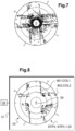
- FIG 7 illustrates a display that would display all obstacle points 75 obtained at the flight point illustrated in the figure 6 . It is noted that a pilot cannot exploit the information displayed.
- FIG 8 illustrates the display of only the relevant points 80 on a display 25, according to a two-dimensional representation 28.
- the relevant points 80 are displayed by the display 25, through pixels, seen from above the aircraft 1 and at 360 degrees around a symbol 29 representing the aircraft 1.
- the displayed information becomes intelligible and thus contributes to flight safety.
- the display 25 can implement a coloring step STP3.1.
- this coloring step STP3.1 the display 25 assigns a color to each relevant point 80 according to the nature of the material of the obstacle detected at this relevant point 80.
- a first relevant point 801 can have a first color COL1 while another relevant point 802 has another color COL2.
- each relevant point 80 can have a first color when the obstacle 60 is detected as belonging to the group of minerals, a second color when the obstacle 60 is detected as belonging to the group of metals, a third color when the obstacle 60 is detected as belonging to the group of organic materials, a fourth color when the obstacle 60 is detected as belonging to the group of elements diffuse in the air.
- the present invention is subject to numerous variations as to its implementation. Although several embodiments have been described, it is understood that it is not conceivable to exhaustively identify all the possible modes.
Landscapes
- Engineering & Computer Science (AREA)
- Physics & Mathematics (AREA)
- General Physics & Mathematics (AREA)
- Aviation & Aerospace Engineering (AREA)
- Radar, Positioning & Navigation (AREA)
- Remote Sensing (AREA)
- Computer Networks & Wireless Communication (AREA)
- Electromagnetism (AREA)
- Optical Radar Systems And Details Thereof (AREA)
- Traffic Control Systems (AREA)
- Radar Systems Or Details Thereof (AREA)
Claims (16)
- Verfahren zum Erkennen von Hindernissen (60) in der Umgebung eines Luftfahrzeugs (1), wobei das Verfahren die folgenden Schritte umfasst:- Abtasten (STP1) eines umgebenden Raums (70) mit einem Hindernissensor (15), wobei der Hindernissensor (15) Positionsdaten in Bezug auf eine Mehrzahl von Hindernispunkten (75) erzeugt,- Bestimmen (STP2) jedes Hindernispunkts (75), der sich innerhalb eines Erfassungsvolumens (85) befindet, wobei jeder Hindernispunkt (75), der sich innerhalb des Erfassungsvolumens (85) befindet, ein relevanter Punkt ist, wobei sich das Erfassungsvolumen (85) von dem abgetasteten umgebenden Raum (70) unterscheidet, jeder Hindernispunkt (75) außerhalb dieses Erfassungsvolumens (85) ein irrelevanter Punkt ist, das Erfassungsvolumen (85) sich zwischen einer eingeschlossenen oberen Ebene (PSUP) und einer eingeschlossenen unteren Ebene (PINF) erstreckt, und die obere Ebene (PSUP) und die untere Ebene (PINF) vertikal oberhalb bzw. unterhalb des Luftfahrzeugs (1) angeordnet sind, wobei das Verfahren einen Schritt des Bestimmens einer maximalen Schwellenhöhe (H1) und einer minimalen Schwellenhöhe (H2) umfasst, wobei die maximale Schwellenhöhe (H1) ein Abstand ist, der die obere Ebene (PSUP) und einen Bezugspunkt (ref) des Luftfahrzeugs in der Vertikalen trennt, wobei die minimale Schwellenhöhe (H2) ein Abstand ist, der den Bezugspunkt (ref) und die untere Ebene (PINF) in der Vertikalen trennt, wobei die maximale Schwellenhöhe (H1) und die minimale Schwellenhöhe (H2) in Abhängigkeit von mindestens einem der folgenden Parameter variabel sind: einer vertikalen Geschwindigkeit des Luftfahrzeugs (1), einer Höhe des Luftfahrzeugs (1) in Bezug zum Boden, einer Vorwärtsgeschwindigkeit des Luftfahrzeugs (1),- Anzeigen (STP3) der relevanten Punkte (80) auf einem Display (25), ohne einen irrelevanten Punkt auf dem Display anzuzeigen.
- Verfahren nach Anspruch 1,
dadurch gekennzeichnet, dass der von dem Hindernissensor abgetastete Umgebungsraum (70) ein abgetastetes Volumen (700) umfasst, das sich über 360 Grad um eine an dem Flugzeug (1) angebrachte Symmetrieachse (AXSYM) erstreckt, wobei sich der Umgebungsraum (70) in Elevation in einem Winkelfeld (85) erstreckt, das sich auf beiden Seiten einer zu der Symmetrieachse (AXSYM) orthogonalen Mittelebene (PMED) erstreckt. - Verfahren nach Anspruch 2,
dadurch gekennzeichnet, dass das Winkelfeld (85) einen Winkel von mindestens 40 Grad aufweist. - Verfahren nach einem der Ansprüche 2 bis 3,
dadurch gekennzeichnet, dass der abgetastete Raum (70) jedes seit einer Messzeit analysierte abgetastete Volumen enthält. - Verfahren nach einem der Ansprüche 1 bis 4,
dadurch gekennzeichnet, dass das Anzeigen einen Schritt umfasst, bei dem die relevanten Punkte (80) in einer zweidimensionalen Darstellung (28) von oben oder von unten auf das Flugzeug (1) gesehen und um 360 Grad um ein das Flugzeug (1) darstellendes Symbol (29) herum angezeigt werden. - Verfahren nach einem der Ansprüche 1 bis 5,
dadurch gekennzeichnet, dass das Erfassungsvolumen (85) an das Luftfahrzeug (1) gekoppelt ist, wobei das Erfassungsvolumen (85) ein Volumen definiert, in dem ein Hindernis in der Lage ist, eine Gefahr für das Luftfahrzeug (1) darzustellen. - Verfahren nach einem der Ansprüche 1 bis 6,
dadurch gekennzeichnet, dass das Verfahren eine Bestimmung einer Hindernishöhe (Hn) jedes Hindernispunkts (75) in Bezug auf eine durch die Referenz (ref) verlaufende Referenzebene (P0) umfasst, wobei jeder relevante Punkt in Bezug auf die Referenzebene (P0) eine Hindernishöhe (Hn) aufweist, die ihn zwischen der oberen Ebene (PSUP) und der unteren Ebene (PINF) platziert. - Verfahren nach Anspruch 7,
dadurch gekennzeichnet, dass die Hindernishöhe (Hn) eines der Hindernispunkte (75) von der Entfernung des Hindernispunktes (75) von der Referenz (ref) sowie von einem Höhenwinkel (alphan) des Hindernispunktes (75) in Bezug auf die Referenz (ref) und einem Peilwinkel (psin) des Hindernispunktes in Bezug auf die Referenz (ref) abhängt. - Verfahren nach einem der Ansprüche 7 bis 8,
dadurch gekennzeichnet, dass die Hindernishöhe (Hn) eines der Hindernispunkte (75) mittels der folgenden Beziehung berechnet wird:
- Verfahren nach einem der Ansprüche 1 bis 9,
dadurch gekennzeichnet, dass die maximale Schwellenhöhe (H1) vom Betrag gleich dem Abstand zwischen einem Scheitelpunkt (2) des Luftfahrzeugs (1) und der Referenz (ref) plus einer ersten Marge (marg1) ist und die minimale Schwellenhöhe (H2) vom Betrag gleich einem Abstands eines Endes (4) eines Fahrwerks (3) von der Referenz (ref) plus einer zweiten Marge (marg2) ist. - Verfahren nach einem der Ansprüche 1 bis 10,
dadurch gekennzeichnet, dass die obere Ebene (PSUP) und die untere Ebene (PINF) horizontal sind. - Verfahren nach einem der Ansprüche 1 bis 10,
dadurch gekennzeichnet, dass die obere Ebene (PSUP) und die untere Ebene (PINF) parallel zu einer Ebene sind, die durch einen Längsgeschwindigkeitsvektor (Vx) und einen Quergeschwindigkeitsvektor (Vy) des Luftfahrzeugs (1) definiert ist. - Verfahren nach einem der Ansprüche 1 bis 12,
dadurch gekennzeichnet, dass das Verfahren einen Schritt des Einfärbens (STP3.1) jedes relevanten Punkts (80) in Abhängigkeit von der Art des Materials eines an diesem relevanten Punkt (80) erfassten Hindernisses umfasst, wobei diese Art aus der Gruppe der Mineralien oder der Gruppe der Metalle oder der Gruppe der organischen Stoffe oder der Gruppe der in der Luft verteilten Elemente stammen kann. - Luftfahrzeug (1), das mit einem Hinderniserkennungssystem (10) ausgestattet ist, wobei das Hinderniserkennungssystem (10) einen Hindernissensor (15) und ein Display (25) umfasst,
dadurch gekennzeichnet, dass das Hinderniserkennungssystem (10) das Verfahren nach einem der Ansprüche 1 bis 13 durchführt, wobei das Hinderniserkennungssystem (10) einen Filter (20) aufweist, der konfiguriert ist, um unter den Hindernispunkten (75) jeden relevanten Punkt (80) zu bestimmen, der sich innerhalb eines vorgegebenen Erfassungsvolumens (85) befindet, wobei sich das Erfassungsvolumen (85) von dem umgebenden Raum (70) unterscheidet, und wobei das Display (25) konfiguriert ist, um die relevanten Punkte (80) anzuzeigen. - Luftfahrzeug nach Anspruch 14,
dadurch gekennzeichnet, dass das Display (25) ein zweidimensionales Display ist. - Luftfahrzeug nach einem der Ansprüche 14 bis 15,
dadurch gekennzeichnet, dass das Luftfahrzeug (1) ein Messsystem (30) aufweist, das einen Rollwinkel und einen Nickwinkel des Luftfahrzeugs (1) misst, wobei der Filter (20) mit dem Messsystem (30) zusammenwirkt.
Applications Claiming Priority (1)
| Application Number | Priority Date | Filing Date | Title |
|---|---|---|---|
| FR2012540A FR3116906B1 (fr) | 2020-12-02 | 2020-12-02 | Procédé et système de détection d’obstacles avec un senseur d’obstacles pour un aéronef |
Publications (2)
| Publication Number | Publication Date |
|---|---|
| EP4009070A1 EP4009070A1 (de) | 2022-06-08 |
| EP4009070B1 true EP4009070B1 (de) | 2024-10-23 |
Family
ID=75438866
Family Applications (1)
| Application Number | Title | Priority Date | Filing Date |
|---|---|---|---|
| EP21206292.1A Active EP4009070B1 (de) | 2020-12-02 | 2021-11-03 | Verfahren und system zur hinderniserkennung mithilfe eines hindernissensors für luftfahrzeug |
Country Status (3)
| Country | Link |
|---|---|
| US (1) | US11862030B2 (de) |
| EP (1) | EP4009070B1 (de) |
| FR (1) | FR3116906B1 (de) |
Families Citing this family (1)
| Publication number | Priority date | Publication date | Assignee | Title |
|---|---|---|---|---|
| FR3143770A1 (fr) | 2022-12-19 | 2024-06-21 | Airbus Helicopters | Procédé et système de détection d’obstacles avec un capteur d’obstacles pour un aéronef à voilure tournante |
Family Cites Families (34)
| Publication number | Priority date | Publication date | Assignee | Title |
|---|---|---|---|---|
| US6804607B1 (en) * | 2001-04-17 | 2004-10-12 | Derek Wood | Collision avoidance system and method utilizing variable surveillance envelope |
| US7095488B2 (en) * | 2003-01-21 | 2006-08-22 | Rosemount Aerospace Inc. | System for profiling objects on terrain forward and below an aircraft utilizing a cross-track laser altimeter |
| FR2932279B1 (fr) * | 2008-06-10 | 2011-08-19 | Thales Sa | Dispositif et procede de surveillance des obstructions dans l'environnement proche d'un aeronef. |
| US7688254B2 (en) * | 2008-06-27 | 2010-03-30 | Honeywell International, Inc. | Display of high-cruise-altitude weather |
| US20130128258A1 (en) * | 2010-04-27 | 2013-05-23 | Saab Ab | Helicopter obstacle detection and information system |
| FR2967285B1 (fr) * | 2010-11-05 | 2013-07-19 | Rockwell Collins France | Procede et dispositif de detection de collisions potentielles pouvant etre mis en oeuvre dans un aeronef |
| US9014880B2 (en) * | 2010-12-21 | 2015-04-21 | General Electric Company | Trajectory based sense and avoid |
| EP2610637B1 (de) * | 2011-12-28 | 2015-10-14 | AIRBUS HELICOPTERS DEUTSCHLAND GmbH | Annäherungswarnsystem für Hubschrauber |
| US8600589B2 (en) * | 2012-04-24 | 2013-12-03 | Exelis, Inc. | Point cloud visualization of acceptable helicopter landing zones based on 4D LIDAR |
| EP2672289B1 (de) | 2012-06-06 | 2014-09-10 | AIRBUS HELICOPTERS DEUTSCHLAND GmbH | Hindernisbenachrichtigungssystem eines Helikopters |
| EP2741106A1 (de) * | 2012-12-10 | 2014-06-11 | AIRBUS HELICOPTERS DEUTSCHLAND GmbH | Hindernis- und Geländewarnradarsystem für ein Rotorflugzeug |
| FR2999725B1 (fr) * | 2012-12-18 | 2015-01-23 | Thales Sa | Procede de reglage d'un secteur de cision/masquage d'un dispositif de scrutation d'environnement, dispositif de reglage et terminal d'operateur correspondants |
| US10963133B2 (en) * | 2014-01-07 | 2021-03-30 | Honeywell International Inc. | Enhanced awareness of obstacle proximity |
| US10431105B2 (en) * | 2014-01-07 | 2019-10-01 | Honeywell International Inc. | Enhanced awareness of obstacle proximity |
| US11022681B2 (en) * | 2014-05-06 | 2021-06-01 | Okkola Technologies, Llc | System and method for measuring and rendering terrain on a display |
| US9568602B1 (en) * | 2014-09-26 | 2017-02-14 | Rockwell Collins, Inc. | Radar system and method of due regard/detect and avoid sensing and weather sensing |
| US20160335898A1 (en) * | 2015-04-09 | 2016-11-17 | Vulcan, Inc. | Automated drone management system |
| CN106556843A (zh) * | 2015-09-28 | 2017-04-05 | 东莞前沿技术研究院 | 三维地形测绘系统以及测绘方法 |
| US9685092B2 (en) * | 2015-10-08 | 2017-06-20 | Honeywell International Inc. | Stationary obstacle identification system |
| US9779629B2 (en) | 2015-10-30 | 2017-10-03 | Honeywell International Inc. | Obstacle advisory system |
| JP6194382B1 (ja) * | 2016-03-18 | 2017-09-06 | 株式会社Subaru | 飛行障害表示装置、飛行障害表示方法及び飛行障害表示プログラム |
| US20170309060A1 (en) | 2016-04-21 | 2017-10-26 | Honeywell International Inc. | Cockpit display for degraded visual environment (dve) using millimeter wave radar (mmwr) |
| US10451422B2 (en) * | 2016-04-28 | 2019-10-22 | Rogerson Aircraft Corporation | System and method for providing persistent mission data to a fleet of vehicles |
| US10571559B2 (en) * | 2016-05-10 | 2020-02-25 | Phase Sensitive Innovations, Inc. | Real-time millimeter wave holographic scanner |
| US9997078B2 (en) * | 2016-09-09 | 2018-06-12 | Garmin International, Inc. | Obstacle determination and display system |
| US10403158B2 (en) * | 2017-04-06 | 2019-09-03 | The Boeing Company | Vertical landing vehicle, situational awareness system, and method thereof |
| GB2564675B (en) * | 2017-07-19 | 2020-04-29 | Ge Aviat Systems Ltd | A landing system for an aerial vehicle |
| GB2568356B (en) * | 2017-09-07 | 2021-12-15 | Borealis Tech Ltd | Improved aircraft ground collision avoidance system |
| US10803760B2 (en) * | 2017-10-13 | 2020-10-13 | Rosemount Aerospace Inc. | Method and system for rendering and displaying a perspective view of aircraft taxi operation |
| US10484667B2 (en) * | 2017-10-31 | 2019-11-19 | Sony Corporation | Generating 3D depth map using parallax |
| US10909875B2 (en) * | 2018-03-29 | 2021-02-02 | Cae Inc. | Method and system for determining a recirculation effect from an obstacle on a main rotor induced velocity of a simulated rotorcraft |
| US10627516B2 (en) * | 2018-07-19 | 2020-04-21 | Luminar Technologies, Inc. | Adjustable pulse characteristics for ground detection in lidar systems |
| AU2019433213B2 (en) * | 2018-12-07 | 2025-06-05 | Joby Aero, Inc. | Aircraft control system and method |
| US10845823B2 (en) * | 2018-12-19 | 2020-11-24 | Joby Aero, Inc. | Vehicle navigation system |
-
2020
- 2020-12-02 FR FR2012540A patent/FR3116906B1/fr active Active
-
2021
- 2021-11-03 EP EP21206292.1A patent/EP4009070B1/de active Active
- 2021-11-17 US US17/528,895 patent/US11862030B2/en active Active
Also Published As
| Publication number | Publication date |
|---|---|
| EP4009070A1 (de) | 2022-06-08 |
| US11862030B2 (en) | 2024-01-02 |
| FR3116906A1 (fr) | 2022-06-03 |
| FR3116906B1 (fr) | 2023-06-30 |
| US20220172631A1 (en) | 2022-06-02 |
Similar Documents
| Publication | Publication Date | Title |
|---|---|---|
| EP1870789B1 (de) | System zur Erfassung von Hindernissen in der Umgebung eines Landungspunktes | |
| EP2717229B1 (de) | Visualisierungssystem für Luftfahrzeuge über einer Landebahn und entsprechendes Verfahren | |
| FR2773609A1 (fr) | Procede et dispositif d'anti-collision terrain pour aeronef, a visualisation perfectionnee | |
| EP1991834B1 (de) | Verfahren und vorrichtung zur automatischen einstellung eines bildes eines flugzeugnavigationsbildschirms | |
| FR2923623A1 (fr) | Systeme de securisation d'un plan de vol pour aeronef | |
| EP4217761B1 (de) | Verfahren zur ortung eines flugzeugs im flug | |
| EP3045920B1 (de) | Verfahren und vorrichtung zur bestimmung der windgeschwindigkeit, die zur optimierung der masse beim abheben eines flugzeugs berücksichtigt werden muss | |
| EP2804023B1 (de) | Systeme und Verfahren zum Nachweis von Reinluftturbulenz | |
| EP2717228A1 (de) | Visualizierungssystem für Flugzeuge und entsprechendes Verfahren | |
| EP2738573A1 (de) | Verfahren und System zur Bestimmung eines Schätzfehlers der Durchquerungszeit der Ionosphäre | |
| BR102016015421A2 (pt) | processo e sistema de exibição de tensões verticais de uma aeronave, produto programa de computador e aeronave associados | |
| EP2161540B1 (de) | Anzeigesystem für Luftfahrzeug, das Mittel zur Darstellung eines Endzielortes umfasst und zugehöriges Anzeigeverfahren | |
| EP4390439A1 (de) | Verfahren und system zur hinderniserkennung mit einem hindernissensor für ein drehflügelflugzeug | |
| EP1936330B1 (de) | Verfahren und System zur Verarbeitung und Visualisierung von Bildern der Umgebung eines Luftfahrzeugs | |
| EP2407953B1 (de) | Verbessertes Pilotenassistenzverfahren für Luftfahrzeug | |
| EP2939050B1 (de) | Verfahren zur bestimmung der geschwindigkeit eines drehflüglers in bezug zur umgebungsluft | |
| EP4009070A1 (de) | Verfahren und system zur hinderniserkennung mithilfe eines hindernissensors für luftfahrzeug | |
| FR3081597A1 (fr) | Procede et dispositif de determination et d'affichage d'une distance de securite d'un giravion en prenant en compte la hauteur des vagues | |
| EP2193477B1 (de) | Verfahren und system zur flugzeugrollunterstützung | |
| FR2938924A1 (fr) | Procede et dispositif de determination de parametres anemometriques d'un aeronef. | |
| WO2014146884A1 (fr) | Procede d'observation d'une zone au moyen d'un drone | |
| CA2615749C (fr) | Dispositif d'aide a la navigation au sol d'un avion sur un aeroport | |
| FR2971343A1 (fr) | Dispositif aeroporte de telemetrie par laser, a division d'impulsions, et systeme de releve topographique correspondant | |
| CA3204386A1 (fr) | Dispositif electronique de stockage d'une base de donnees terrain, procede de generation d'une telle base de donnees, systeme avionique, procede de surveillance et programmes d'ordinateur associe | |
| EP4286885B1 (de) | Verfahren und system zur kontinuierlichen flugverwaltung eines integrierten strahlgenerators |
Legal Events
| Date | Code | Title | Description |
|---|---|---|---|
| PUAI | Public reference made under article 153(3) epc to a published international application that has entered the european phase |
Free format text: ORIGINAL CODE: 0009012 |
|
| STAA | Information on the status of an ep patent application or granted ep patent |
Free format text: STATUS: THE APPLICATION HAS BEEN PUBLISHED |
|
| STAA | Information on the status of an ep patent application or granted ep patent |
Free format text: STATUS: REQUEST FOR EXAMINATION WAS MADE |
|
| AK | Designated contracting states |
Kind code of ref document: A1 Designated state(s): AL AT BE BG CH CY CZ DE DK EE ES FI FR GB GR HR HU IE IS IT LI LT LU LV MC MK MT NL NO PL PT RO RS SE SI SK SM TR |
|
| 17P | Request for examination filed |
Effective date: 20220525 |
|
| RBV | Designated contracting states (corrected) |
Designated state(s): AL AT BE BG CH CY CZ DE DK EE ES FI FR GB GR HR HU IE IS IT LI LT LU LV MC MK MT NL NO PL PT RO RS SE SI SK SM TR |
|
| P01 | Opt-out of the competence of the unified patent court (upc) registered |
Effective date: 20230530 |
|
| STAA | Information on the status of an ep patent application or granted ep patent |
Free format text: STATUS: EXAMINATION IS IN PROGRESS |
|
| 17Q | First examination report despatched |
Effective date: 20230809 |
|
| GRAP | Despatch of communication of intention to grant a patent |
Free format text: ORIGINAL CODE: EPIDOSNIGR1 |
|
| STAA | Information on the status of an ep patent application or granted ep patent |
Free format text: STATUS: GRANT OF PATENT IS INTENDED |
|
| INTG | Intention to grant announced |
Effective date: 20240802 |
|
| GRAS | Grant fee paid |
Free format text: ORIGINAL CODE: EPIDOSNIGR3 |
|
| GRAA | (expected) grant |
Free format text: ORIGINAL CODE: 0009210 |
|
| STAA | Information on the status of an ep patent application or granted ep patent |
Free format text: STATUS: THE PATENT HAS BEEN GRANTED |
|
| AK | Designated contracting states |
Kind code of ref document: B1 Designated state(s): AL AT BE BG CH CY CZ DE DK EE ES FI FR GB GR HR HU IE IS IT LI LT LU LV MC MK MT NL NO PL PT RO RS SE SI SK SM TR |
|
| REG | Reference to a national code |
Ref country code: GB Ref legal event code: FG4D Free format text: NOT ENGLISH |
|
| REG | Reference to a national code |
Ref country code: CH Ref legal event code: EP |
|
| REG | Reference to a national code |
Ref country code: DE Ref legal event code: R096 Ref document number: 602021020589 Country of ref document: DE |
|
| REG | Reference to a national code |
Ref country code: IE Ref legal event code: FG4D Free format text: LANGUAGE OF EP DOCUMENT: FRENCH |
|
| REG | Reference to a national code |
Ref country code: LT Ref legal event code: MG9D |
|
| REG | Reference to a national code |
Ref country code: AT Ref legal event code: MK05 Ref document number: 1735262 Country of ref document: AT Kind code of ref document: T Effective date: 20241023 |
|
| PG25 | Lapsed in a contracting state [announced via postgrant information from national office to epo] |
Ref country code: NL Free format text: LAPSE BECAUSE OF FAILURE TO SUBMIT A TRANSLATION OF THE DESCRIPTION OR TO PAY THE FEE WITHIN THE PRESCRIBED TIME-LIMIT Effective date: 20241023 |
|
| PG25 | Lapsed in a contracting state [announced via postgrant information from national office to epo] |
Ref country code: NL Free format text: LAPSE BECAUSE OF FAILURE TO SUBMIT A TRANSLATION OF THE DESCRIPTION OR TO PAY THE FEE WITHIN THE PRESCRIBED TIME-LIMIT Effective date: 20241023 |
|
| PG25 | Lapsed in a contracting state [announced via postgrant information from national office to epo] |
Ref country code: PT Free format text: LAPSE BECAUSE OF FAILURE TO SUBMIT A TRANSLATION OF THE DESCRIPTION OR TO PAY THE FEE WITHIN THE PRESCRIBED TIME-LIMIT Effective date: 20250224 Ref country code: IS Free format text: LAPSE BECAUSE OF FAILURE TO SUBMIT A TRANSLATION OF THE DESCRIPTION OR TO PAY THE FEE WITHIN THE PRESCRIBED TIME-LIMIT Effective date: 20250223 Ref country code: HR Free format text: LAPSE BECAUSE OF FAILURE TO SUBMIT A TRANSLATION OF THE DESCRIPTION OR TO PAY THE FEE WITHIN THE PRESCRIBED TIME-LIMIT Effective date: 20241023 |
|
| PG25 | Lapsed in a contracting state [announced via postgrant information from national office to epo] |
Ref country code: FI Free format text: LAPSE BECAUSE OF FAILURE TO SUBMIT A TRANSLATION OF THE DESCRIPTION OR TO PAY THE FEE WITHIN THE PRESCRIBED TIME-LIMIT Effective date: 20241023 |
|
| PG25 | Lapsed in a contracting state [announced via postgrant information from national office to epo] |
Ref country code: BG Free format text: LAPSE BECAUSE OF FAILURE TO SUBMIT A TRANSLATION OF THE DESCRIPTION OR TO PAY THE FEE WITHIN THE PRESCRIBED TIME-LIMIT Effective date: 20241023 |
|
| PG25 | Lapsed in a contracting state [announced via postgrant information from national office to epo] |
Ref country code: ES Free format text: LAPSE BECAUSE OF FAILURE TO SUBMIT A TRANSLATION OF THE DESCRIPTION OR TO PAY THE FEE WITHIN THE PRESCRIBED TIME-LIMIT Effective date: 20241023 |
|
| PG25 | Lapsed in a contracting state [announced via postgrant information from national office to epo] |
Ref country code: NO Free format text: LAPSE BECAUSE OF FAILURE TO SUBMIT A TRANSLATION OF THE DESCRIPTION OR TO PAY THE FEE WITHIN THE PRESCRIBED TIME-LIMIT Effective date: 20250123 |
|
| PG25 | Lapsed in a contracting state [announced via postgrant information from national office to epo] |
Ref country code: LV Free format text: LAPSE BECAUSE OF FAILURE TO SUBMIT A TRANSLATION OF THE DESCRIPTION OR TO PAY THE FEE WITHIN THE PRESCRIBED TIME-LIMIT Effective date: 20241023 Ref country code: AT Free format text: LAPSE BECAUSE OF FAILURE TO SUBMIT A TRANSLATION OF THE DESCRIPTION OR TO PAY THE FEE WITHIN THE PRESCRIBED TIME-LIMIT Effective date: 20241023 Ref country code: GR Free format text: LAPSE BECAUSE OF FAILURE TO SUBMIT A TRANSLATION OF THE DESCRIPTION OR TO PAY THE FEE WITHIN THE PRESCRIBED TIME-LIMIT Effective date: 20250124 |
|
| PG25 | Lapsed in a contracting state [announced via postgrant information from national office to epo] |
Ref country code: PL Free format text: LAPSE BECAUSE OF FAILURE TO SUBMIT A TRANSLATION OF THE DESCRIPTION OR TO PAY THE FEE WITHIN THE PRESCRIBED TIME-LIMIT Effective date: 20241023 |
|
| PG25 | Lapsed in a contracting state [announced via postgrant information from national office to epo] |
Ref country code: RS Free format text: LAPSE BECAUSE OF FAILURE TO SUBMIT A TRANSLATION OF THE DESCRIPTION OR TO PAY THE FEE WITHIN THE PRESCRIBED TIME-LIMIT Effective date: 20250123 |
|
| REG | Reference to a national code |
Ref country code: CH Ref legal event code: PL |
|
| PG25 | Lapsed in a contracting state [announced via postgrant information from national office to epo] |
Ref country code: SM Free format text: LAPSE BECAUSE OF FAILURE TO SUBMIT A TRANSLATION OF THE DESCRIPTION OR TO PAY THE FEE WITHIN THE PRESCRIBED TIME-LIMIT Effective date: 20241023 |
|
| PG25 | Lapsed in a contracting state [announced via postgrant information from national office to epo] |
Ref country code: MC Free format text: LAPSE BECAUSE OF FAILURE TO SUBMIT A TRANSLATION OF THE DESCRIPTION OR TO PAY THE FEE WITHIN THE PRESCRIBED TIME-LIMIT Effective date: 20241023 |
|
| PG25 | Lapsed in a contracting state [announced via postgrant information from national office to epo] |
Ref country code: DK Free format text: LAPSE BECAUSE OF FAILURE TO SUBMIT A TRANSLATION OF THE DESCRIPTION OR TO PAY THE FEE WITHIN THE PRESCRIBED TIME-LIMIT Effective date: 20241023 |
|
| PG25 | Lapsed in a contracting state [announced via postgrant information from national office to epo] |
Ref country code: LU Free format text: LAPSE BECAUSE OF NON-PAYMENT OF DUE FEES Effective date: 20241103 |
|
| REG | Reference to a national code |
Ref country code: CH Ref legal event code: PL |
|
| PG25 | Lapsed in a contracting state [announced via postgrant information from national office to epo] |
Ref country code: EE Free format text: LAPSE BECAUSE OF FAILURE TO SUBMIT A TRANSLATION OF THE DESCRIPTION OR TO PAY THE FEE WITHIN THE PRESCRIBED TIME-LIMIT Effective date: 20241023 |
|
| PG25 | Lapsed in a contracting state [announced via postgrant information from national office to epo] |
Ref country code: CH Free format text: LAPSE BECAUSE OF NON-PAYMENT OF DUE FEES Effective date: 20241130 |
|
| PG25 | Lapsed in a contracting state [announced via postgrant information from national office to epo] |
Ref country code: RO Free format text: LAPSE BECAUSE OF FAILURE TO SUBMIT A TRANSLATION OF THE DESCRIPTION OR TO PAY THE FEE WITHIN THE PRESCRIBED TIME-LIMIT Effective date: 20241023 |
|
| REG | Reference to a national code |
Ref country code: DE Ref legal event code: R097 Ref document number: 602021020589 Country of ref document: DE |
|
| PG25 | Lapsed in a contracting state [announced via postgrant information from national office to epo] |
Ref country code: SK Free format text: LAPSE BECAUSE OF FAILURE TO SUBMIT A TRANSLATION OF THE DESCRIPTION OR TO PAY THE FEE WITHIN THE PRESCRIBED TIME-LIMIT Effective date: 20241023 |
|
| PG25 | Lapsed in a contracting state [announced via postgrant information from national office to epo] |
Ref country code: CZ Free format text: LAPSE BECAUSE OF FAILURE TO SUBMIT A TRANSLATION OF THE DESCRIPTION OR TO PAY THE FEE WITHIN THE PRESCRIBED TIME-LIMIT Effective date: 20241023 |
|
| REG | Reference to a national code |
Ref country code: BE Ref legal event code: MM Effective date: 20241130 |
|
| PLBE | No opposition filed within time limit |
Free format text: ORIGINAL CODE: 0009261 |
|
| STAA | Information on the status of an ep patent application or granted ep patent |
Free format text: STATUS: NO OPPOSITION FILED WITHIN TIME LIMIT |
|
| PG25 | Lapsed in a contracting state [announced via postgrant information from national office to epo] |
Ref country code: SE Free format text: LAPSE BECAUSE OF FAILURE TO SUBMIT A TRANSLATION OF THE DESCRIPTION OR TO PAY THE FEE WITHIN THE PRESCRIBED TIME-LIMIT Effective date: 20241023 |
|
| 26N | No opposition filed |
Effective date: 20250724 |
|
| PG25 | Lapsed in a contracting state [announced via postgrant information from national office to epo] |
Ref country code: BE Free format text: LAPSE BECAUSE OF NON-PAYMENT OF DUE FEES Effective date: 20241130 |
|
| PG25 | Lapsed in a contracting state [announced via postgrant information from national office to epo] |
Ref country code: IE Free format text: LAPSE BECAUSE OF NON-PAYMENT OF DUE FEES Effective date: 20241103 |
|
| PGFP | Annual fee paid to national office [announced via postgrant information from national office to epo] |
Ref country code: DE Payment date: 20251119 Year of fee payment: 5 |
|
| PGFP | Annual fee paid to national office [announced via postgrant information from national office to epo] |
Ref country code: IT Payment date: 20251125 Year of fee payment: 5 |
|
| PGFP | Annual fee paid to national office [announced via postgrant information from national office to epo] |
Ref country code: FR Payment date: 20251126 Year of fee payment: 5 |
|
| PG25 | Lapsed in a contracting state [announced via postgrant information from national office to epo] |
Ref country code: HU Free format text: LAPSE BECAUSE OF FAILURE TO SUBMIT A TRANSLATION OF THE DESCRIPTION OR TO PAY THE FEE WITHIN THE PRESCRIBED TIME-LIMIT; INVALID AB INITIO Effective date: 20211103 |
|
| PG25 | Lapsed in a contracting state [announced via postgrant information from national office to epo] |
Ref country code: CY Free format text: LAPSE BECAUSE OF FAILURE TO SUBMIT A TRANSLATION OF THE DESCRIPTION OR TO PAY THE FEE WITHIN THE PRESCRIBED TIME-LIMIT; INVALID AB INITIO Effective date: 20211103 |
|
| PG25 | Lapsed in a contracting state [announced via postgrant information from national office to epo] |
Ref country code: TR Free format text: LAPSE BECAUSE OF FAILURE TO SUBMIT A TRANSLATION OF THE DESCRIPTION OR TO PAY THE FEE WITHIN THE PRESCRIBED TIME-LIMIT Effective date: 20241023 |
|
| PG25 | Lapsed in a contracting state [announced via postgrant information from national office to epo] |
Ref country code: SI Free format text: LAPSE BECAUSE OF FAILURE TO SUBMIT A TRANSLATION OF THE DESCRIPTION OR TO PAY THE FEE WITHIN THE PRESCRIBED TIME-LIMIT Effective date: 20241023 |
|
| PG25 | Lapsed in a contracting state [announced via postgrant information from national office to epo] |
Ref country code: LT Free format text: LAPSE BECAUSE OF FAILURE TO SUBMIT A TRANSLATION OF THE DESCRIPTION OR TO PAY THE FEE WITHIN THE PRESCRIBED TIME-LIMIT Effective date: 20241023 |