EP4009071B1 - Verfahren und vorrichtung für radargenauigkeitsmessungen - Google Patents
Verfahren und vorrichtung für radargenauigkeitsmessungen Download PDFInfo
- Publication number
- EP4009071B1 EP4009071B1 EP22151904.4A EP22151904A EP4009071B1 EP 4009071 B1 EP4009071 B1 EP 4009071B1 EP 22151904 A EP22151904 A EP 22151904A EP 4009071 B1 EP4009071 B1 EP 4009071B1
- Authority
- EP
- European Patent Office
- Prior art keywords
- antenna
- radar
- radar sensor
- test
- cover
- Prior art date
- Legal status (The legal status is an assumption and is not a legal conclusion. Google has not performed a legal analysis and makes no representation as to the accuracy of the status listed.)
- Active
Links
Images

Classifications
-
- H—ELECTRICITY
- H01—ELECTRIC ELEMENTS
- H01Q—ANTENNAS, i.e. RADIO AERIALS
- H01Q1/00—Details of, or arrangements associated with, antennas
- H01Q1/42—Housings not intimately mechanically associated with radiating elements, e.g. radome
-
- G—PHYSICS
- G01—MEASURING; TESTING
- G01R—MEASURING ELECTRIC VARIABLES; MEASURING MAGNETIC VARIABLES
- G01R29/00—Arrangements for measuring or indicating electric quantities not covered by groups G01R19/00 - G01R27/00
- G01R29/08—Measuring electromagnetic field characteristics
- G01R29/0807—Measuring electromagnetic field characteristics characterised by the application
- G01R29/0814—Field measurements related to measuring influence on or from apparatus, components or humans, e.g. in ESD, EMI, EMC, EMP testing, measuring radiation leakage; detecting presence of micro- or radiowave emitters; dosimetry; testing shielding; measurements related to lightning
- G01R29/0835—Testing shielding, e.g. for efficiency
-
- G—PHYSICS
- G01—MEASURING; TESTING
- G01S—RADIO DIRECTION-FINDING; RADIO NAVIGATION; DETERMINING DISTANCE OR VELOCITY BY USE OF RADIO WAVES; LOCATING OR PRESENCE-DETECTING BY USE OF THE REFLECTION OR RERADIATION OF RADIO WAVES; ANALOGOUS ARRANGEMENTS USING OTHER WAVES
- G01S13/00—Systems using the reflection or reradiation of radio waves, e.g. radar systems; Analogous systems using reflection or reradiation of waves whose nature or wavelength is irrelevant or unspecified
- G01S13/87—Combinations of radar systems, e.g. primary radar and secondary radar
-
- G—PHYSICS
- G01—MEASURING; TESTING
- G01S—RADIO DIRECTION-FINDING; RADIO NAVIGATION; DETERMINING DISTANCE OR VELOCITY BY USE OF RADIO WAVES; LOCATING OR PRESENCE-DETECTING BY USE OF THE REFLECTION OR RERADIATION OF RADIO WAVES; ANALOGOUS ARRANGEMENTS USING OTHER WAVES
- G01S7/00—Details of systems according to groups G01S13/00, G01S15/00, G01S17/00
- G01S7/02—Details of systems according to groups G01S13/00, G01S15/00, G01S17/00 of systems according to group G01S13/00
- G01S7/40—Means for monitoring or calibrating
-
- H—ELECTRICITY
- H01—ELECTRIC ELEMENTS
- H01Q—ANTENNAS, i.e. RADIO AERIALS
- H01Q1/00—Details of, or arrangements associated with, antennas
- H01Q1/42—Housings not intimately mechanically associated with radiating elements, e.g. radome
- H01Q1/421—Means for correcting aberrations introduced by a radome
-
- G—PHYSICS
- G01—MEASURING; TESTING
- G01S—RADIO DIRECTION-FINDING; RADIO NAVIGATION; DETERMINING DISTANCE OR VELOCITY BY USE OF RADIO WAVES; LOCATING OR PRESENCE-DETECTING BY USE OF THE REFLECTION OR RERADIATION OF RADIO WAVES; ANALOGOUS ARRANGEMENTS USING OTHER WAVES
- G01S13/00—Systems using the reflection or reradiation of radio waves, e.g. radar systems; Analogous systems using reflection or reradiation of waves whose nature or wavelength is irrelevant or unspecified
- G01S13/003—Bistatic radar systems; Multistatic radar systems
-
- G—PHYSICS
- G01—MEASURING; TESTING
- G01S—RADIO DIRECTION-FINDING; RADIO NAVIGATION; DETERMINING DISTANCE OR VELOCITY BY USE OF RADIO WAVES; LOCATING OR PRESENCE-DETECTING BY USE OF THE REFLECTION OR RERADIATION OF RADIO WAVES; ANALOGOUS ARRANGEMENTS USING OTHER WAVES
- G01S7/00—Details of systems according to groups G01S13/00, G01S15/00, G01S17/00
- G01S7/02—Details of systems according to groups G01S13/00, G01S15/00, G01S17/00 of systems according to group G01S13/00
- G01S7/40—Means for monitoring or calibrating
- G01S7/4052—Means for monitoring or calibrating by simulation of echoes
- G01S7/4082—Means for monitoring or calibrating by simulation of echoes using externally generated reference signals, e.g. via remote reflector or transponder
- G01S7/4086—Means for monitoring or calibrating by simulation of echoes using externally generated reference signals, e.g. via remote reflector or transponder in a calibrating environment, e.g. anechoic chamber
Definitions
- the invention relates to a use of a test setup for evaluating the impact of radar antenna covers on radar waves.
- the test setup comprises a test antenna, a radar sensor antenna and a radar sensor antenna cover.
- radar antennas are covered with a weatherproof enclosure, called a radome or bumper to protect the antenna.
- a weatherproof enclosure called a radome or bumper to protect the antenna.
- the radome/bumper is constructed of material that minimally influences the radar waves, the angular accuracy of a radar sensor is affected and the antenna beam pattern is distored.
- a measurement method and setup to measure the effects on the radar wave caused by the radome/bumper is a measurement method and setup to measure the effects on the radar wave caused by the radome/bumper.
- WO 2015/043935 A1 discloses a method for monitoring a cover of a Doppler radar sensor of a rail vehicle, using two adjacent antenna arrays, wherein a first radio signal is transmitted by a first antenna array, the said radio signal is at least partly reflected by the cover to be monitored and measured by a second antenna array. On the basis of the reflected signal, measured by the second antenna, dirt present on the cover is automatically detected.
- said document does not show a test antenna comprising several antenna elements in elevation and/or azimuth direction to evaluate the effect of radar waves caused by a radome or bumper.
- WO 2015/043935 A1 only detects dirt on a cover based on reflection measurements, wherein the transmitting antenna array and the receiving antenna array are located at the same side of the cover and since said document does not disclose the measurement of the influence on the radome/bumper material on radar waves with a test antenna.
- a test antenna, a radar sensor antenna, a radar sensor antenna cover There is a need to provide a system and method with a test antenna, a radar sensor antenna, a radar sensor antenna cover.
- EP3115804A1 discloses a test rig for testing a distance radar device for determining distance and speed of obstacles.
- JP 2011 122892A discloses a test apparatus and a test method for testing a radome boresight error.
- EP 3258288A1 is prior art under Art. 54(3) EPC and discloses a test setup is used for measuring the impact of automotive radome bodies.
- a test setup is used for measuring the impact of radar antenna covers, which antenna covers are not automotive radome bodies as disclosed in EP3258288A1 .
- the test set up comprises:
- the analyzer unit is configured to compare measurement data taken with the radar sensor antenna cover, which covers the radar sensor antenna, and measurement data taken without the radar sensor antenna cover , wherein for measuring the angular accuracy effects caused by the radar sensor antenna cover, the radar sensor antenna is designed to measure the elevation and azimuth angle of the received signal gone through the radar sensor antenna cover, and the analyzer unit is designed to compare this data with the measurement data of the elevation and azimuth angle of the radar sensor signal not gone through the radar sensor antenna cover.
- the test antenna is designed to measure the radar signals, emitted by the radar sensor antenna, gone through the radar sensor antenna cover and the analyzing unit is designed to compare this data with the measurement data obtained when the test antenna receives the radar radiation emitted by the radar sensor antenna without going through the radar sensor antenna cover.
- Fig. 1 illustrates an exemplary test setup for measuring the impact of radar antenna covers, comprising a radar sensor antenna 1, a test antenna 2, a radar sensor cover 3 and an analyzer unit 4.
- the radar sensor antenna 1 may exemplarily be a multi-antenna array consisting of several antenna elements 5, each antenna element 5 being connected to a phase shifter 6.
- the phase shifters 6 in this exemplary case, are connected via a connection line 7 to a control/processing unit 8 that may be part of the analyzing unit 4, for configuring the phase of the applied signals.
- the phase shifters 6 are connected via a connection line 9 to a transmission/receiving unit 10 that may be part of the analyzing unit 4, configured to transmit/receive radar signals.
- the transmission/receiving unit 10 is connected to the control/processing unit 8. It is also conceivable that the transmission/receiving unit 10 and/or the control/processing unit 8 are provided as separate units and are not necessarily included into the analyzer unit 4.
- the test antenna 2 comprises several antenna elements 11 in elevation and/or azimuth direction. Furthermore the antenna elements 11 may be exemplarily connected to a phase shifter 12, wherein the phase shifters 12 are connected via a connection line 13 to the control/processing unit 8 that may be part of an analyzing unit 4, for configuring the phase of the applied signals. Furthermore, the phase shifters 12 are connected via a connection line 14 to a transmission/receiving unit 15 that may be part of the analyzing unit 4, configured to transmit/receive radar signals. Thus, the feed current for each antenna element 11 passes through a phase shifter 12. The transmission/receiving unit 15 is connected to the control/processing unit 8. It is also conceivable that the transmission/receiving unit 15 and/or the control/processing unit 8 are provided as separate units and are not necessarily included into the analyzer unit 4.
- each element 11 is provided with a phase shifter 12
- radar radiation is generated, identical to radar echos that are normally generated, when radar radiation is reflected by a real object.
- the test antenna 2 is able to simulate targets since the control/processing unit 8 in combination with the transmitter/receiver unit 15 are configured to produce radar echos to simulate targets.
- Fig. 1 shows a material 3 that covers the radar sensor antenna 1.
- the material 3 is located between the radar sensor antenna 1 and the test antenna 2 and influences the radar radiation going through the material 3.
- the cover material 3 is drawn with a dashed line, to point out, that measurements are conducted with the material between the two antennas and without the material between the two antennas.
- the analyzing unit 4 compares measurement data taken without material influencing the radar radiation 3, such as a radome, bumper, weather shield or similar that covers the radar sensor antenna 1, and measurement data taken with material influencing the radar radiation 3.
- the radar sensor antenna 1 measures the elevation and azimuth angle of the received signal gone through the material, and the analyzing unit 4 compares this data with the measurement data of the elevation and azimuth angle of the radar sensor signal not gone through the cover material 3.
- the test antenna 2 measures the radar signals, emitted by the radar sensor antenna 1, gone through the material 3 and the analyzing unit 4 compares this data with the measurement data obtained when the test antenna 2 receives the radar radiation emitted by the radar sensor antenna 1 without going through the material 3.
- Fig. 1 which shows a so called passive electronically scanned array (PESA) including several phase shifters and antenna elements, but only one transmitter/receiver per antenna, an active electronically scanned array (AESA) antenna, which comprises a separate transmitter and/or receiver unit for each antenna element, can be implemented.
- PESA passive electronically scanned array
- AESA active electronically scanned array
- the test setup according to the present invention does not require corner reflectors to measure the angular accuracy impact of the cover material as known from state of the art solutions.
- the known state of the art method requires the measurement of corner reflector positions (R, azimuth, elevation) with the radome cover for several corner reflectors, which means increased effort and which is very time consuming.
- the test setup of the present invention allows the measurement of the angular accuracy impact of the cover material within seconds and additionally the measurement of the antenna beam pattern distortion caused by the antenna cover is possible within seconds.
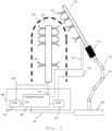
- Fig. 2 illustrates an exemplary test setup for measuring the impact of radar antenna covers, comprising a radar sensor antenna 101, a test antenna 102, a radar sensor cover 103, an analyzer unit 104 and a robotic arm 116 including a connection adapter 117 to connect the test antenna 102 to the robotic arm 116.
- the robotic arm is mounted on a mounting plate 118.
- the radar sensor antenna 101 may exemplarily be a multi-antenna array consisting of several antenna elements 105 each antenna element 105 being connected to a transmission/receiver unit 110 via a connection line 109 and with a process/control unit 108 via a connection line 107.
- a first antenna array is provided, but a duplicated second antenna array symmetrically mirrored to the first antenna array is shown. Additionally or alternatively, a radar sensor antenna with antenna arrays that are orientated in different directions in respect to the first antenna array are conceivable.
- the transmission/receiving unit 110 is connected to the control/processing unit 108.
- transmission/receiving unit 110 and/or the transmission/receiving unit 115 and/or the control/processing unit 108 are provided as separate units and are not necessarily included into the analyzer unit 104.
- the test antenna 102 comprises several antenna elements 111 in elevation and/or azimuth direction. Furthermore the antenna elements 111 are connected via a connection line 113 to the control/processing unit 108 that may be part of the analyzing unit 104, for configuring the phase of the applied signals. Furthermore, the antenna elements 111 are connected via a connection line 114 to a transmission/receiving unit 115 that may be part of the analyzing unit 104, configured to transmit/receive radar signals.
- each element 111 is configured to be switchable individually and controllable via the control/processing unit 108, it is possible to create a beam of radar waves that can be electronically steered to point in different directions, without moving the test antenna 102, and generate radar radiation that is identical to radar echos that are normally generated, when radar radiation is reflected by a real object.
- the test antenna is able to simulate targets.
- a robotic arm 116 is provided to allow a movement of the test antenna 102 to a desired location around the radar sensor antenna 101.
- the movement of the robotic arm 116 is realized by motors 119 that move the robotic arm 116 in x, y and z direction.
- the robotic arm is controlled by the control processing unit 108 and connected to the control/processing unit 108 via connection line 120. Since robotic arms are well known and available in different configurations, no more details are given regarding the robotic arm.
- a connection adapter 117 to connect the test antenna 102 to the robotic arm 116, and a mounting plate 118 to mount the robotic arm and ensure mechanical stability is shown.
- Fig. 2 shows a material 103 that covers the radar sensor antenna 101.
- the material 103 is located between the radar sensor antenna 101 and the test antenna 102 and influences the radar radiation going through the material 103.
- the cover material 103 is drawn with a dashed line, to point out that measurements are conducted with the material 103 between the two antennas 101, 102 and without the material 103 between the two antennas 101, 102.
- the analyzing unit 104 compares measurement data, taken without material 103 influencing the radar radiation, such as a radome, bumper, weather shield or similar that covers the radar sensor antenna 101, and measurement data taken with material 103 influencing the radar radiation 103.
- the radar sensor antenna 101 measures the elevation and azimuth angle of the received signal gone through the material 103 and the analyzing unit 104 compares this data with the measurement data of the elevation and azimuth angle of the radar sensor signal not gone through the cover material 103.
- the test antenna 102 For measuring the antenna beam pattern distortion caused by the cover material 103, the test antenna 102 measures the radar signals, emitted by the radar sensor antenna 101, gone through the material 103 and the analyzing unit 104 compares this data with the measurement data obtained when the test antenna 102 receives the radar radiation emitted by the radar sensor antenna 101 without going through the material 103.
- the test setup according to the present invention does not require corner reflectors to measure the angular accuracy impact of the cover material as known from state of the art solutions.
- the known state of the art method requires the measurement of corner reflector positions (R, azimuth, elevation) with and without radome cover for several corner reflectors, which means a higher effort and is very time consuming.
- the test setup of the present invention allows the measurement of the angular accuracy impact of the cover material 103 within seconds.
- the additional robotic arm 116 further reduces the testing time, since in addition to the beam movement performed without antenna movement the robot arm 116 movement can position the test antenna 102 and can define a rough scan position.
- the fine positioning, so called fine tuning of the beam is conducted by the electronic beam movement.
- the robot arm 116 can be adapted to fulfill a further function, which is to place the radome/bumper 103 around the radar sensor antenna 101 or to remove the radome/bumper 103 being positioned around the radar sensor antenna 101 depending on the measurement step. This configuration is especially time saving when doing automated production line testing.
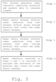
- Fig. 3 shows a flow chart of the inventive test method with the test antenna 2, 102 switched to transmission mode generating radar radiation and the radar sensor antenna 1, 101 switched to receive mode receiving radar radiation.
- radar radiation comprising elevation and azimuth data
- the radar sensor antenna 1, 101 receives the radiation from the test antenna 2, 102 without going through a material 3, 103 that covers the radar sensor antenna 1, 101.
- the measurement without any material 3, 103 between the radar sensor antenna 1, 101 and the test antenna 2, 102 is required as a reference measurement.
- the radar sensor antenna 1, 101 receives the radar radiation generated from the test antenna 2, 102, wherein the radar radiation has gone through a material 3, 103 that covers the radar sensor antenna 1, 101.
- Step 4 analyzes the radar radiation received directly, without going through any material 3, 103 and the radar radiation received after having gone through a material 3, 103 that influences radar radiation. Based on a measurement without a sensor antenna cover 3, 103 and another measurement with a sensor antenna cover 3, 103, the impact of the cover 3, 103 on the radar radiation emitted from the test antenna is evaluated. The information related to the impact of the sensor antenna cover on the radar radiation is required to maintain angular accuracy of the radar sensor antenna, when a cover 3, 103 that influences the radar radiation by absorption, reflection or scattering, covers the radar sensor antenna 1, 101.
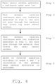
- Fig. 4 shows a flow chart of the inventive test method with the radar sensor antenna 1, 101 switched to transmission mode, generating a continuous radar wave (cw), and the test antenna 2, 102 switched to receive mode, receiving the radar waves emitted by the radar sensor antenna 1, 101.
- the generation of the continuous radar wave is shown in step 5 of the inventive test method.
- step 6 the emitted continuous radar wave is received and measured by the test antenna 2, 102 without going through the material 3, 103 that covers the radar sensor antenna 1, 101.
- step 7 the emitted continuous radar wave is received and measured by the test antenna 2, 102 having gone through the material 3, 103 that covers the radar sensor antenna 1, 101.
- step 8 based on the two measurements, one measurement without the influence of the sensor antenna cover material 3, 103 and one measurement with the influence of the sensor antenna cover material 3, 103, the calculation of the antenna beam pattern distortion caused by the cover material 3, 103 is performed.
Landscapes
- Engineering & Computer Science (AREA)
- Physics & Mathematics (AREA)
- General Physics & Mathematics (AREA)
- Radar, Positioning & Navigation (AREA)
- Remote Sensing (AREA)
- Computer Networks & Wireless Communication (AREA)
- Electromagnetism (AREA)
- Radar Systems Or Details Thereof (AREA)
- Variable-Direction Aerials And Aerial Arrays (AREA)
- Details Of Aerials (AREA)
Claims (5)
- Verwendung eines Messaufbaus zum Messen der Auswirkung von Radarantennenabdeckungen, wobei die Antennenabdeckungen nicht Auto-Radomkörper sind,der Messaufbau umfassend:- eine Messantenne (2), die konfiguriert ist, um Radarstrahlung zu erzeugen und um Radarstrahlung zu empfangen- eine Radarsensorantenne (1), die konfiguriert ist, um Radarstrahlung, die durch die Messantenne (2) ausgesendet wird, zu empfangen und um Radarstrahlung, die die durch die Messantenne (2) empfangen werden soll, zu erzeugen- eine Radarsensorantennenabdeckung (3)- eine Analysatoreinheit (4),wobei die Messantenne (2) mehrere Antennenelemente (11) in Elevations- und/oder Azimutrichtung umfasst,dadurch gekennzeichnet,dass die Analysatoreinheit (4) konfiguriert ist, um Messdaten, die mit der Radarsensorantennenabdeckung (3), die die Radarsensorantenne (1) abdeckt, genommen werden, mit Messdaten, die ohne die Radarsensorantennenabdeckung (3) genommen werden, zu vergleichen, wobei zum Messen der Winkelgenauigkeitseffekte, die durch die Radarsensorantennenabdeckung (3) verursacht werden, die Radarsensorantenne (1) ausgelegt ist, um den Elevations- und Azimutwinkel des empfangenen Signals, das durch die Radarsensorantennenabdeckung (3) hindurchgegangen ist, zu messen, und die Analysatoreinheit (4) ausgelegt ist, um diese Daten mit den Messdaten des Elevations- und Azimutwinkels des Radarsensorsignals, das nicht durch die Radarsensorantennenabdeckung (3) hindurchgegangen ist, zu vergleichen, unddass zum Messen des Antennenstrahlmusterverzerrung, die durch die Radarsensorantennenabdeckung (3) verursacht wird, die Messantenne (2) ausgelegt ist, um die Radarsignale, die durch die Radarsensorantenne (1) ausgesendet werden, die durch die Radarsensorantennenabdeckung (3) hindurchgegangen sind, zu messen, und die Analysatoreinheit (4) ausgelegt ist, um diese Daten mit den Messdaten, die erhalten werden, wenn die Messantenne (2) die Radarstrahlung, die durch die Radarsensorantenne (1) ausgesendet wird, ohne durch die Radarsensorantennenabdeckung (3) hindurchzugehen, empfängt, zu vergleichen.
- Verfahren nach Anspruch 1,
wobei die Radarstrahlung, die durch die Messantenne (2) erzeugt wird, derart ist, dass Radarechos ausgesendet werden, um ein Ziel zu simulieren. - Verwendung nach einem der Ansprüche 1 bis 2, wobei jedes der Messantennenelemente (11) konfiguriert ist, um einzeln schaltbar zu sein.
- Verwendung nach Anspruch 3, wobei die schaltbaren Messantennenelemente (11) konfiguriert sind, um einen Strahl zu bilden.
- Verwendung nach einem der Ansprüche 1 bis 4,
wobei die Radarsensorantenne (1) ein Mehrantennen-Array ist.
Applications Claiming Priority (2)
| Application Number | Priority Date | Filing Date | Title |
|---|---|---|---|
| US15/494,092 US10581150B2 (en) | 2017-04-21 | 2017-04-21 | Method and apparatus for radar accuracy measurements |
| EP17172341.4A EP3392669B8 (de) | 2017-04-21 | 2017-05-23 | Verfahren und vorrichtung für radargenauigkeitsmessungen |
Related Parent Applications (2)
| Application Number | Title | Priority Date | Filing Date |
|---|---|---|---|
| EP17172341.4A Division EP3392669B8 (de) | 2017-04-21 | 2017-05-23 | Verfahren und vorrichtung für radargenauigkeitsmessungen |
| EP17172341.4A Division-Into EP3392669B8 (de) | 2017-04-21 | 2017-05-23 | Verfahren und vorrichtung für radargenauigkeitsmessungen |
Publications (2)
| Publication Number | Publication Date |
|---|---|
| EP4009071A1 EP4009071A1 (de) | 2022-06-08 |
| EP4009071B1 true EP4009071B1 (de) | 2025-01-08 |
Family
ID=58765755
Family Applications (2)
| Application Number | Title | Priority Date | Filing Date |
|---|---|---|---|
| EP22151904.4A Active EP4009071B1 (de) | 2017-04-21 | 2017-05-23 | Verfahren und vorrichtung für radargenauigkeitsmessungen |
| EP17172341.4A Active EP3392669B8 (de) | 2017-04-21 | 2017-05-23 | Verfahren und vorrichtung für radargenauigkeitsmessungen |
Family Applications After (1)
| Application Number | Title | Priority Date | Filing Date |
|---|---|---|---|
| EP17172341.4A Active EP3392669B8 (de) | 2017-04-21 | 2017-05-23 | Verfahren und vorrichtung für radargenauigkeitsmessungen |
Country Status (3)
| Country | Link |
|---|---|
| US (1) | US10581150B2 (de) |
| EP (2) | EP4009071B1 (de) |
| JP (1) | JP7018280B2 (de) |
Families Citing this family (18)
| Publication number | Priority date | Publication date | Assignee | Title |
|---|---|---|---|---|
| EP3871003B1 (de) * | 2018-10-24 | 2025-02-26 | ABB Schweiz AG | Radarsensor und roboter |
| CN113614561B (zh) * | 2019-03-22 | 2024-11-22 | 株式会社村田制作所 | 雷达装置以及具备该雷达装置的车辆 |
| EP3751306B1 (de) * | 2019-06-11 | 2024-04-03 | Rohde & Schwarz GmbH & Co. KG | System und verfahren zum testen eines radars |
| US11442158B2 (en) * | 2019-08-01 | 2022-09-13 | Rohde & Schwarz Gmbh & Co. Kg | Multiple input multiple output imaging array and corresponding imaging method |
| US20210063532A1 (en) * | 2019-08-27 | 2021-03-04 | Qualcomm Incorporated | Apparatus and method for radar calibration |
| US11313786B2 (en) | 2020-02-04 | 2022-04-26 | Aptiv Technologies Limited | Testing system for detectors useful on vehicles |
| EP3869616B8 (de) * | 2020-02-21 | 2023-11-22 | Rohde & Schwarz GmbH & Co. KG | Messsystem zur messung eines durch ein radom eingeführten winkelfehlers und entsprechendes verfahren |
| KR102328695B1 (ko) * | 2020-03-23 | 2021-11-18 | 주식회사 아이유플러스 | 복수의 타겟들에 대한 테스트를 위한 레이더 테스트 시스템 및 방법 |
| EP4136707B1 (de) * | 2020-04-15 | 2025-05-28 | Perisens GmbH | Vorrichtungen, systeme und verfahren zur messung von radomen |
| EP3968045B1 (de) * | 2020-09-14 | 2025-06-04 | Rohde & Schwarz GmbH & Co. KG | Abbildungssystem und verfahren zur materialcharakterisierung einer probe |
| CN112986931B (zh) * | 2021-02-08 | 2023-07-21 | 西安电子工程研究所 | 一种基于脉间积累的相控阵雷达接收通道校准测试方法 |
| EP4113745A1 (de) * | 2021-06-30 | 2023-01-04 | Perisens GmbH | Vereinfachte radom-messsysteme und verfahren |
| CN113721081B (zh) * | 2021-09-27 | 2024-03-15 | 国家无线电监测中心检测中心 | 一种天线罩的最佳厚度的测量方法和系统 |
| EP4246174A1 (de) * | 2022-03-15 | 2023-09-20 | Rockwell Collins, Inc. | Erkennung von antennenanordnungsausfällen |
| US12372615B2 (en) | 2022-09-08 | 2025-07-29 | Raytheon Company | Multi-target near-field test system |
| DE102022213636A1 (de) | 2022-12-14 | 2024-06-20 | Robert Bosch Gesellschaft mit beschränkter Haftung | Verfahren und Vorrichtung zum Überprüfen eines Kfz-Radarsenders in einem Kraftfahrzeug |
| US12345750B2 (en) * | 2023-06-27 | 2025-07-01 | Rohde & Schwarz Gmbh & Co. Kg | Method and radiation detector for automotive radar tests |
| EP4506727B1 (de) * | 2023-08-11 | 2026-02-25 | GM Cruise Holdings LLC | Systeme und verfahren zur erhöhung der radarauflösung unter verwendung von halbkohärenten radarnetzwerken |
Family Cites Families (20)
| Publication number | Priority date | Publication date | Assignee | Title |
|---|---|---|---|---|
| US3953850A (en) * | 1974-10-08 | 1976-04-27 | The United States Of America As Represented By The Secretary Of The Army | Radar test facility communication system |
| JPH02181683A (ja) * | 1989-01-06 | 1990-07-16 | Mitsubishi Electric Corp | レーダシミュレータ装置 |
| US5047782A (en) * | 1990-06-04 | 1991-09-10 | Westinghouse Electric Corp. | System and method for simulating targets for a radar receiver utilizing an optical link |
| US5066921A (en) * | 1990-08-01 | 1991-11-19 | General Dynamics, Electronics Division | Radome diagnostic system |
| US5371505A (en) * | 1993-04-22 | 1994-12-06 | Microwave Power Devices, Inc. | Radome test systems and methods |
| US5485159A (en) * | 1994-08-24 | 1996-01-16 | Delco Electronics Corporation | Apparatus and method to detect radar radome obstruction |
| DE19805584C2 (de) * | 1998-02-12 | 2000-04-13 | Daimler Chrysler Ag | System und Verfahren zur Materialüberprüfung von Werkstoffen, sowie Werkstoff und Verfahren zu seiner Herstellung |
| DE102005018163A1 (de) * | 2005-04-19 | 2006-11-02 | Deutsches Zentrum für Luft- und Raumfahrt e.V. | Signal-Simulationseinrichtung |
| IL174746A0 (en) * | 2006-04-03 | 2007-03-08 | Israel Aerospace Ind Ltd | Methods and systems for generating virtual radar targets |
| US7999624B2 (en) * | 2007-04-24 | 2011-08-16 | City University Of Hong Kong | Radiation source |
| US20090135076A1 (en) * | 2007-11-28 | 2009-05-28 | Senglee Foo | Linear antenna array with azimuth beam augmentation by axial rotation |
| JP2011122892A (ja) * | 2009-12-09 | 2011-06-23 | Yokohama Rubber Co Ltd:The | レドームのボアサイトエラー試験装置及びレドームのボアサイトエラー試験方法 |
| JP5716475B2 (ja) * | 2011-03-22 | 2015-05-13 | 株式会社デンソー | アレイアンテナの軸調整方法及び軸調整システム |
| FR2978249B1 (fr) * | 2011-07-22 | 2013-07-26 | Thales Sa | Dispositif de calibration et de test pour une antenne active notamment une antenne de pointe avant d'un radar aeroporte |
| CN103412227B (zh) * | 2013-08-27 | 2015-07-08 | 中国舰船研究设计中心 | 一种基于绕射抑制的频选雷达天线罩传输性能测试系统及其方法 |
| DE102013219391A1 (de) | 2013-09-26 | 2015-03-26 | Siemens Aktiengesellschaft | Verfahren zur Überwachung einer Sensorabdeckung sowie danach betriebene Sensoreinheit |
| CN103913470B (zh) * | 2014-03-24 | 2017-03-29 | 西安电子科技大学 | 基于远区电磁场分布的共形承载天线的罩体缺陷检测方法 |
| DE102016112402A1 (de) * | 2015-07-08 | 2017-01-12 | Dspace Digital Signal Processing And Control Engineering Gmbh | Prüfstand zum Test eines Abstandsradargeräts zur Entfernungs- und Geschwindigkeitsbestimmung von Hindernissen |
| CN204925281U (zh) * | 2015-08-25 | 2015-12-30 | 深圳光启创新技术有限公司 | 雷达罩测试装置 |
| EP3258288B1 (de) * | 2016-06-14 | 2024-07-31 | Rohde & Schwarz GmbH & Co. KG | Verfahren zum testen der übertragungs- und reflexionseigenschaften eines radom-körpers sowie vorrichtung zum testen der übertragungs- und reflexionseigenschaften eines radom-körpers |
-
2017
- 2017-04-21 US US15/494,092 patent/US10581150B2/en active Active
- 2017-05-23 EP EP22151904.4A patent/EP4009071B1/de active Active
- 2017-05-23 EP EP17172341.4A patent/EP3392669B8/de active Active
- 2017-09-26 JP JP2017184364A patent/JP7018280B2/ja active Active
Also Published As
| Publication number | Publication date |
|---|---|
| EP3392669A1 (de) | 2018-10-24 |
| EP4009071A1 (de) | 2022-06-08 |
| US20180306903A1 (en) | 2018-10-25 |
| EP3392669B1 (de) | 2022-04-06 |
| JP2018179961A (ja) | 2018-11-15 |
| JP7018280B2 (ja) | 2022-02-10 |
| US10581150B2 (en) | 2020-03-03 |
| EP3392669B8 (de) | 2022-05-25 |
Similar Documents
| Publication | Publication Date | Title |
|---|---|---|
| EP4009071B1 (de) | Verfahren und vorrichtung für radargenauigkeitsmessungen | |
| US12050240B2 (en) | Radome measuring system and method | |
| EP3258288B1 (de) | Verfahren zum testen der übertragungs- und reflexionseigenschaften eines radom-körpers sowie vorrichtung zum testen der übertragungs- und reflexionseigenschaften eines radom-körpers | |
| JP6734847B2 (ja) | レーダセンサ、レーダセンサシステム、および点反射物体と面反射物体を測定するための水平垂直デジタルビーム形成を用いて物体の位置を特定する方法 | |
| CN102135610B (zh) | 一种用于人体毫米波成像安检系统的近场实时校准方法 | |
| WO2019023717A1 (en) | INTERFEROMETRIC RADAR SYSTEM FOR MONITORING MULTIPLE OBJECTS FOR THE ACQUISITION OF PRECISE INFORMATION DATA ON TEMPORAL AND SPACE POSITIONS | |
| AU2020364169B2 (en) | Calibrating radars and tracking space objects | |
| US11852731B2 (en) | Test bench for testing a distance sensor operating with electromagnetic waves | |
| Jha | The millimeter Wave (mmW) radar characterization, testing, verification challenges and opportunities | |
| JP2001264427A (ja) | レーダ装置 | |
| JP5102403B1 (ja) | レーダ試験装置 | |
| RU2709417C1 (ru) | Способ определения диаграммы направленности фазированной антенной решетки | |
| KR20170092906A (ko) | 레이더 장치 | |
| JP2010237069A (ja) | レーダ反射断面積計測装置 | |
| KR20240055085A (ko) | 가상 센서를 사용하는 레이더 시스템 및 방법 | |
| RU2707506C1 (ru) | Способ контроля работоспособности радиолокационной станции и комплекс для его осуществления | |
| JP2005121421A (ja) | 海上用rcs計測装置 | |
| EP4641952A1 (de) | Over-the-air-messsystem und -verfahren | |
| EP4246174A1 (de) | Erkennung von antennenanordnungsausfällen | |
| EP4667969A1 (de) | Radarsensor | |
| KR102018139B1 (ko) | 도플러 신호 발생장치 및 그를 이용한 사각지대 감시장치 검사 시스템 | |
| CA3045206A1 (en) | Synthetic aperture radar method and synthetic aperture radar system |
Legal Events
| Date | Code | Title | Description |
|---|---|---|---|
| PUAI | Public reference made under article 153(3) epc to a published international application that has entered the european phase |
Free format text: ORIGINAL CODE: 0009012 |
|
| STAA | Information on the status of an ep patent application or granted ep patent |
Free format text: STATUS: THE APPLICATION HAS BEEN PUBLISHED |
|
| AC | Divisional application: reference to earlier application |
Ref document number: 3392669 Country of ref document: EP Kind code of ref document: P |
|
| AK | Designated contracting states |
Kind code of ref document: A1 Designated state(s): AL AT BE BG CH CY CZ DE DK EE ES FI FR GB GR HR HU IE IS IT LI LT LU LV MC MK MT NL NO PL PT RO RS SE SI SK SM TR |
|
| STAA | Information on the status of an ep patent application or granted ep patent |
Free format text: STATUS: REQUEST FOR EXAMINATION WAS MADE |
|
| 17P | Request for examination filed |
Effective date: 20220602 |
|
| RBV | Designated contracting states (corrected) |
Designated state(s): AL AT BE BG CH CY CZ DE DK EE ES FI FR GB GR HR HU IE IS IT LI LT LU LV MC MK MT NL NO PL PT RO RS SE SI SK SM TR |
|
| P01 | Opt-out of the competence of the unified patent court (upc) registered |
Effective date: 20230525 |
|
| GRAP | Despatch of communication of intention to grant a patent |
Free format text: ORIGINAL CODE: EPIDOSNIGR1 |
|
| STAA | Information on the status of an ep patent application or granted ep patent |
Free format text: STATUS: GRANT OF PATENT IS INTENDED |
|
| INTG | Intention to grant announced |
Effective date: 20240918 |
|
| GRAS | Grant fee paid |
Free format text: ORIGINAL CODE: EPIDOSNIGR3 |
|
| GRAA | (expected) grant |
Free format text: ORIGINAL CODE: 0009210 |
|
| STAA | Information on the status of an ep patent application or granted ep patent |
Free format text: STATUS: THE PATENT HAS BEEN GRANTED |
|
| AC | Divisional application: reference to earlier application |
Ref document number: 3392669 Country of ref document: EP Kind code of ref document: P |
|
| AK | Designated contracting states |
Kind code of ref document: B1 Designated state(s): AL AT BE BG CY CZ DE DK EE ES FI FR GB GR HR HU IS IT LT LU LV MC MK MT NL NO PL PT RO RS SE SI SK SM TR |
|
| RBV | Designated contracting states (corrected) |
Designated state(s): AL AT BE BG CY CZ DE DK EE ES FI FR GB GR HR HU IS IT LT LU LV MC MK MT NL NO PL PT RO RS SE SI SK SM TR |
|
| REG | Reference to a national code |
Ref country code: GB Ref legal event code: FG4D |
|
| REG | Reference to a national code |
Ref country code: DE Ref legal event code: R096 Ref document number: 602017087314 Country of ref document: DE |
|
| REG | Reference to a national code |
Ref country code: LT Ref legal event code: MG9D |
|
| REG | Reference to a national code |
Ref country code: NL Ref legal event code: MP Effective date: 20250108 |
|
| REG | Reference to a national code |
Ref country code: AT Ref legal event code: MK05 Ref document number: 1758667 Country of ref document: AT Kind code of ref document: T Effective date: 20250108 |
|
| PG25 | Lapsed in a contracting state [announced via postgrant information from national office to epo] |
Ref country code: NL Free format text: LAPSE BECAUSE OF FAILURE TO SUBMIT A TRANSLATION OF THE DESCRIPTION OR TO PAY THE FEE WITHIN THE PRESCRIBED TIME-LIMIT Effective date: 20250108 |
|
| PG25 | Lapsed in a contracting state [announced via postgrant information from national office to epo] |
Ref country code: RS Free format text: LAPSE BECAUSE OF FAILURE TO SUBMIT A TRANSLATION OF THE DESCRIPTION OR TO PAY THE FEE WITHIN THE PRESCRIBED TIME-LIMIT Effective date: 20250408 |
|
| PG25 | Lapsed in a contracting state [announced via postgrant information from national office to epo] |
Ref country code: FI Free format text: LAPSE BECAUSE OF FAILURE TO SUBMIT A TRANSLATION OF THE DESCRIPTION OR TO PAY THE FEE WITHIN THE PRESCRIBED TIME-LIMIT Effective date: 20250108 |
|
| PG25 | Lapsed in a contracting state [announced via postgrant information from national office to epo] |
Ref country code: PL Free format text: LAPSE BECAUSE OF FAILURE TO SUBMIT A TRANSLATION OF THE DESCRIPTION OR TO PAY THE FEE WITHIN THE PRESCRIBED TIME-LIMIT Effective date: 20250108 |
|
| PGFP | Annual fee paid to national office [announced via postgrant information from national office to epo] |
Ref country code: DE Payment date: 20250519 Year of fee payment: 9 |
|
| PG25 | Lapsed in a contracting state [announced via postgrant information from national office to epo] |
Ref country code: ES Free format text: LAPSE BECAUSE OF FAILURE TO SUBMIT A TRANSLATION OF THE DESCRIPTION OR TO PAY THE FEE WITHIN THE PRESCRIBED TIME-LIMIT Effective date: 20250108 |
|
| PG25 | Lapsed in a contracting state [announced via postgrant information from national office to epo] |
Ref country code: NO Free format text: LAPSE BECAUSE OF FAILURE TO SUBMIT A TRANSLATION OF THE DESCRIPTION OR TO PAY THE FEE WITHIN THE PRESCRIBED TIME-LIMIT Effective date: 20250408 Ref country code: IS Free format text: LAPSE BECAUSE OF FAILURE TO SUBMIT A TRANSLATION OF THE DESCRIPTION OR TO PAY THE FEE WITHIN THE PRESCRIBED TIME-LIMIT Effective date: 20250508 |
|
| PG25 | Lapsed in a contracting state [announced via postgrant information from national office to epo] |
Ref country code: HR Free format text: LAPSE BECAUSE OF FAILURE TO SUBMIT A TRANSLATION OF THE DESCRIPTION OR TO PAY THE FEE WITHIN THE PRESCRIBED TIME-LIMIT Effective date: 20250108 |
|
| PG25 | Lapsed in a contracting state [announced via postgrant information from national office to epo] |
Ref country code: PT Free format text: LAPSE BECAUSE OF FAILURE TO SUBMIT A TRANSLATION OF THE DESCRIPTION OR TO PAY THE FEE WITHIN THE PRESCRIBED TIME-LIMIT Effective date: 20250508 Ref country code: LV Free format text: LAPSE BECAUSE OF FAILURE TO SUBMIT A TRANSLATION OF THE DESCRIPTION OR TO PAY THE FEE WITHIN THE PRESCRIBED TIME-LIMIT Effective date: 20250108 |
|
| PGFP | Annual fee paid to national office [announced via postgrant information from national office to epo] |
Ref country code: FR Payment date: 20250521 Year of fee payment: 9 |
|
| PG25 | Lapsed in a contracting state [announced via postgrant information from national office to epo] |
Ref country code: GR Free format text: LAPSE BECAUSE OF FAILURE TO SUBMIT A TRANSLATION OF THE DESCRIPTION OR TO PAY THE FEE WITHIN THE PRESCRIBED TIME-LIMIT Effective date: 20250409 Ref country code: BG Free format text: LAPSE BECAUSE OF FAILURE TO SUBMIT A TRANSLATION OF THE DESCRIPTION OR TO PAY THE FEE WITHIN THE PRESCRIBED TIME-LIMIT Effective date: 20250108 |
|
| PG25 | Lapsed in a contracting state [announced via postgrant information from national office to epo] |
Ref country code: AT Free format text: LAPSE BECAUSE OF FAILURE TO SUBMIT A TRANSLATION OF THE DESCRIPTION OR TO PAY THE FEE WITHIN THE PRESCRIBED TIME-LIMIT Effective date: 20250108 |
|
| PG25 | Lapsed in a contracting state [announced via postgrant information from national office to epo] |
Ref country code: SE Free format text: LAPSE BECAUSE OF FAILURE TO SUBMIT A TRANSLATION OF THE DESCRIPTION OR TO PAY THE FEE WITHIN THE PRESCRIBED TIME-LIMIT Effective date: 20250108 |
|
| PG25 | Lapsed in a contracting state [announced via postgrant information from national office to epo] |
Ref country code: SM Free format text: LAPSE BECAUSE OF FAILURE TO SUBMIT A TRANSLATION OF THE DESCRIPTION OR TO PAY THE FEE WITHIN THE PRESCRIBED TIME-LIMIT Effective date: 20250108 |
|
| REG | Reference to a national code |
Ref country code: DE Ref legal event code: R097 Ref document number: 602017087314 Country of ref document: DE |
|
| PG25 | Lapsed in a contracting state [announced via postgrant information from national office to epo] |
Ref country code: DK Free format text: LAPSE BECAUSE OF FAILURE TO SUBMIT A TRANSLATION OF THE DESCRIPTION OR TO PAY THE FEE WITHIN THE PRESCRIBED TIME-LIMIT Effective date: 20250108 |
|
| PG25 | Lapsed in a contracting state [announced via postgrant information from national office to epo] |
Ref country code: CZ Free format text: LAPSE BECAUSE OF FAILURE TO SUBMIT A TRANSLATION OF THE DESCRIPTION OR TO PAY THE FEE WITHIN THE PRESCRIBED TIME-LIMIT Effective date: 20250108 Ref country code: EE Free format text: LAPSE BECAUSE OF FAILURE TO SUBMIT A TRANSLATION OF THE DESCRIPTION OR TO PAY THE FEE WITHIN THE PRESCRIBED TIME-LIMIT Effective date: 20250108 |
|
| PG25 | Lapsed in a contracting state [announced via postgrant information from national office to epo] |
Ref country code: RO Free format text: LAPSE BECAUSE OF FAILURE TO SUBMIT A TRANSLATION OF THE DESCRIPTION OR TO PAY THE FEE WITHIN THE PRESCRIBED TIME-LIMIT Effective date: 20250108 |
|
| PG25 | Lapsed in a contracting state [announced via postgrant information from national office to epo] |
Ref country code: SK Free format text: LAPSE BECAUSE OF FAILURE TO SUBMIT A TRANSLATION OF THE DESCRIPTION OR TO PAY THE FEE WITHIN THE PRESCRIBED TIME-LIMIT Effective date: 20250108 |
|
| PLBE | No opposition filed within time limit |
Free format text: ORIGINAL CODE: 0009261 |
|
| STAA | Information on the status of an ep patent application or granted ep patent |
Free format text: STATUS: NO OPPOSITION FILED WITHIN TIME LIMIT |
|
| 26N | No opposition filed |
Effective date: 20251009 |
|
| PG25 | Lapsed in a contracting state [announced via postgrant information from national office to epo] |
Ref country code: LU Free format text: LAPSE BECAUSE OF NON-PAYMENT OF DUE FEES Effective date: 20250523 |
|
| PG25 | Lapsed in a contracting state [announced via postgrant information from national office to epo] |
Ref country code: IT Free format text: LAPSE BECAUSE OF FAILURE TO SUBMIT A TRANSLATION OF THE DESCRIPTION OR TO PAY THE FEE WITHIN THE PRESCRIBED TIME-LIMIT Effective date: 20250108 |
|
| REG | Reference to a national code |
Ref country code: BE Ref legal event code: MM Effective date: 20250531 |
|
| PG25 | Lapsed in a contracting state [announced via postgrant information from national office to epo] |
Ref country code: MC Free format text: LAPSE BECAUSE OF FAILURE TO SUBMIT A TRANSLATION OF THE DESCRIPTION OR TO PAY THE FEE WITHIN THE PRESCRIBED TIME-LIMIT Effective date: 20250108 |
|
| PGFP | Annual fee paid to national office [announced via postgrant information from national office to epo] |
Ref country code: GB Payment date: 20260324 Year of fee payment: 10 |
|
| PG25 | Lapsed in a contracting state [announced via postgrant information from national office to epo] |
Ref country code: BE Free format text: LAPSE BECAUSE OF NON-PAYMENT OF DUE FEES Effective date: 20250531 |