EP4009072A1 - Procédé, appareil de commande et véhicule destinés à la validation de la localisation d'un véhicule par référencement à des objets statiques dans la zone environnante - Google Patents
Procédé, appareil de commande et véhicule destinés à la validation de la localisation d'un véhicule par référencement à des objets statiques dans la zone environnante Download PDFInfo
- Publication number
- EP4009072A1 EP4009072A1 EP21212923.3A EP21212923A EP4009072A1 EP 4009072 A1 EP4009072 A1 EP 4009072A1 EP 21212923 A EP21212923 A EP 21212923A EP 4009072 A1 EP4009072 A1 EP 4009072A1
- Authority
- EP
- European Patent Office
- Prior art keywords
- vehicle
- localization
- static
- error
- localization system
- Prior art date
- Legal status (The legal status is an assumption and is not a legal conclusion. Google has not performed a legal analysis and makes no representation as to the accuracy of the status listed.)
- Withdrawn
Links
Images


Classifications
-
- G—PHYSICS
- G01—MEASURING; TESTING
- G01S—RADIO DIRECTION-FINDING; RADIO NAVIGATION; DETERMINING DISTANCE OR VELOCITY BY USE OF RADIO WAVES; LOCATING OR PRESENCE-DETECTING BY USE OF THE REFLECTION OR RERADIATION OF RADIO WAVES; ANALOGOUS ARRANGEMENTS USING OTHER WAVES
- G01S7/00—Details of systems according to groups G01S13/00, G01S15/00, G01S17/00
- G01S7/48—Details of systems according to groups G01S13/00, G01S15/00, G01S17/00 of systems according to group G01S17/00
- G01S7/4808—Evaluating distance, position or velocity data
-
- G—PHYSICS
- G01—MEASURING; TESTING
- G01C—MEASURING DISTANCES, LEVELS OR BEARINGS; SURVEYING; NAVIGATION; GYROSCOPIC INSTRUMENTS; PHOTOGRAMMETRY OR VIDEOGRAMMETRY
- G01C21/00—Navigation; Navigational instruments not provided for in groups G01C1/00 - G01C19/00
- G01C21/20—Instruments for performing navigational calculations
-
- G—PHYSICS
- G01—MEASURING; TESTING
- G01C—MEASURING DISTANCES, LEVELS OR BEARINGS; SURVEYING; NAVIGATION; GYROSCOPIC INSTRUMENTS; PHOTOGRAMMETRY OR VIDEOGRAMMETRY
- G01C21/00—Navigation; Navigational instruments not provided for in groups G01C1/00 - G01C19/00
- G01C21/26—Navigation; Navigational instruments not provided for in groups G01C1/00 - G01C19/00 specially adapted for navigation in a road network
- G01C21/34—Route searching; Route guidance
- G01C21/36—Input/output arrangements for on-board computers
- G01C21/3605—Destination input or retrieval
- G01C21/3608—Destination input or retrieval using speech input, e.g. using speech recognition
-
- G—PHYSICS
- G01—MEASURING; TESTING
- G01S—RADIO DIRECTION-FINDING; RADIO NAVIGATION; DETERMINING DISTANCE OR VELOCITY BY USE OF RADIO WAVES; LOCATING OR PRESENCE-DETECTING BY USE OF THE REFLECTION OR RERADIATION OF RADIO WAVES; ANALOGOUS ARRANGEMENTS USING OTHER WAVES
- G01S13/00—Systems using the reflection or reradiation of radio waves, e.g. radar systems; Analogous systems using reflection or reradiation of waves whose nature or wavelength is irrelevant or unspecified
- G01S13/02—Systems using reflection of radio waves, e.g. primary radar systems; Analogous systems
- G01S13/06—Systems determining position data of a target
- G01S13/42—Simultaneous measurement of distance and other co-ordinates
-
- G—PHYSICS
- G01—MEASURING; TESTING
- G01S—RADIO DIRECTION-FINDING; RADIO NAVIGATION; DETERMINING DISTANCE OR VELOCITY BY USE OF RADIO WAVES; LOCATING OR PRESENCE-DETECTING BY USE OF THE REFLECTION OR RERADIATION OF RADIO WAVES; ANALOGOUS ARRANGEMENTS USING OTHER WAVES
- G01S13/00—Systems using the reflection or reradiation of radio waves, e.g. radar systems; Analogous systems using reflection or reradiation of waves whose nature or wavelength is irrelevant or unspecified
- G01S13/86—Combinations of radar systems with non-radar systems, e.g. sonar, direction finder
-
- G—PHYSICS
- G01—MEASURING; TESTING
- G01S—RADIO DIRECTION-FINDING; RADIO NAVIGATION; DETERMINING DISTANCE OR VELOCITY BY USE OF RADIO WAVES; LOCATING OR PRESENCE-DETECTING BY USE OF THE REFLECTION OR RERADIATION OF RADIO WAVES; ANALOGOUS ARRANGEMENTS USING OTHER WAVES
- G01S13/00—Systems using the reflection or reradiation of radio waves, e.g. radar systems; Analogous systems using reflection or reradiation of waves whose nature or wavelength is irrelevant or unspecified
- G01S13/88—Radar or analogous systems specially adapted for specific applications
- G01S13/93—Radar or analogous systems specially adapted for specific applications for anti-collision purposes
- G01S13/931—Radar or analogous systems specially adapted for specific applications for anti-collision purposes of land vehicles
-
- G—PHYSICS
- G01—MEASURING; TESTING
- G01S—RADIO DIRECTION-FINDING; RADIO NAVIGATION; DETERMINING DISTANCE OR VELOCITY BY USE OF RADIO WAVES; LOCATING OR PRESENCE-DETECTING BY USE OF THE REFLECTION OR RERADIATION OF RADIO WAVES; ANALOGOUS ARRANGEMENTS USING OTHER WAVES
- G01S17/00—Systems using the reflection or reradiation of electromagnetic waves other than radio waves, e.g. lidar systems
- G01S17/86—Combinations of lidar systems with systems other than lidar, radar or sonar, e.g. with direction finders
-
- G—PHYSICS
- G01—MEASURING; TESTING
- G01S—RADIO DIRECTION-FINDING; RADIO NAVIGATION; DETERMINING DISTANCE OR VELOCITY BY USE OF RADIO WAVES; LOCATING OR PRESENCE-DETECTING BY USE OF THE REFLECTION OR RERADIATION OF RADIO WAVES; ANALOGOUS ARRANGEMENTS USING OTHER WAVES
- G01S17/00—Systems using the reflection or reradiation of electromagnetic waves other than radio waves, e.g. lidar systems
- G01S17/88—Lidar systems specially adapted for specific applications
- G01S17/93—Lidar systems specially adapted for specific applications for anti-collision purposes
- G01S17/931—Lidar systems specially adapted for specific applications for anti-collision purposes of land vehicles
-
- G—PHYSICS
- G01—MEASURING; TESTING
- G01S—RADIO DIRECTION-FINDING; RADIO NAVIGATION; DETERMINING DISTANCE OR VELOCITY BY USE OF RADIO WAVES; LOCATING OR PRESENCE-DETECTING BY USE OF THE REFLECTION OR RERADIATION OF RADIO WAVES; ANALOGOUS ARRANGEMENTS USING OTHER WAVES
- G01S19/00—Satellite radio beacon positioning systems; Determining position, velocity or attitude using signals transmitted by such systems
- G01S19/38—Determining a navigation solution using signals transmitted by a satellite radio beacon positioning system
- G01S19/39—Determining a navigation solution using signals transmitted by a satellite radio beacon positioning system the satellite radio beacon positioning system transmitting time-stamped messages, e.g. GPS [Global Positioning System], GLONASS [Global Orbiting Navigation Satellite System] or GALILEO
- G01S19/396—Determining accuracy or reliability of position or pseudorange measurements
-
- G—PHYSICS
- G01—MEASURING; TESTING
- G01S—RADIO DIRECTION-FINDING; RADIO NAVIGATION; DETERMINING DISTANCE OR VELOCITY BY USE OF RADIO WAVES; LOCATING OR PRESENCE-DETECTING BY USE OF THE REFLECTION OR RERADIATION OF RADIO WAVES; ANALOGOUS ARRANGEMENTS USING OTHER WAVES
- G01S7/00—Details of systems according to groups G01S13/00, G01S15/00, G01S17/00
- G01S7/02—Details of systems according to groups G01S13/00, G01S15/00, G01S17/00 of systems according to group G01S13/00
- G01S7/40—Means for monitoring or calibrating
- G01S7/4004—Means for monitoring or calibrating of parts of a radar system
-
- G—PHYSICS
- G01—MEASURING; TESTING
- G01S—RADIO DIRECTION-FINDING; RADIO NAVIGATION; DETERMINING DISTANCE OR VELOCITY BY USE OF RADIO WAVES; LOCATING OR PRESENCE-DETECTING BY USE OF THE REFLECTION OR RERADIATION OF RADIO WAVES; ANALOGOUS ARRANGEMENTS USING OTHER WAVES
- G01S7/00—Details of systems according to groups G01S13/00, G01S15/00, G01S17/00
- G01S7/02—Details of systems according to groups G01S13/00, G01S15/00, G01S17/00 of systems according to group G01S13/00
- G01S7/41—Details of systems according to groups G01S13/00, G01S15/00, G01S17/00 of systems according to group G01S13/00 using analysis of echo signal for target characterisation; Target signature; Target cross-section
- G01S7/414—Discriminating targets with respect to background clutter
-
- G—PHYSICS
- G01—MEASURING; TESTING
- G01S—RADIO DIRECTION-FINDING; RADIO NAVIGATION; DETERMINING DISTANCE OR VELOCITY BY USE OF RADIO WAVES; LOCATING OR PRESENCE-DETECTING BY USE OF THE REFLECTION OR RERADIATION OF RADIO WAVES; ANALOGOUS ARRANGEMENTS USING OTHER WAVES
- G01S7/00—Details of systems according to groups G01S13/00, G01S15/00, G01S17/00
- G01S7/48—Details of systems according to groups G01S13/00, G01S15/00, G01S17/00 of systems according to group G01S17/00
- G01S7/4802—Details of systems according to groups G01S13/00, G01S15/00, G01S17/00 of systems according to group G01S17/00 using analysis of echo signal for target characterisation; Target signature; Target cross-section
-
- G—PHYSICS
- G01—MEASURING; TESTING
- G01S—RADIO DIRECTION-FINDING; RADIO NAVIGATION; DETERMINING DISTANCE OR VELOCITY BY USE OF RADIO WAVES; LOCATING OR PRESENCE-DETECTING BY USE OF THE REFLECTION OR RERADIATION OF RADIO WAVES; ANALOGOUS ARRANGEMENTS USING OTHER WAVES
- G01S7/00—Details of systems according to groups G01S13/00, G01S15/00, G01S17/00
- G01S7/48—Details of systems according to groups G01S13/00, G01S15/00, G01S17/00 of systems according to group G01S17/00
- G01S7/497—Means for monitoring or calibrating
-
- G—PHYSICS
- G06—COMPUTING OR CALCULATING; COUNTING
- G06V—IMAGE OR VIDEO RECOGNITION OR UNDERSTANDING
- G06V20/00—Scenes; Scene-specific elements
- G06V20/50—Context or environment of the image
- G06V20/56—Context or environment of the image exterior to a vehicle by using sensors mounted on the vehicle
-
- G—PHYSICS
- G01—MEASURING; TESTING
- G01S—RADIO DIRECTION-FINDING; RADIO NAVIGATION; DETERMINING DISTANCE OR VELOCITY BY USE OF RADIO WAVES; LOCATING OR PRESENCE-DETECTING BY USE OF THE REFLECTION OR RERADIATION OF RADIO WAVES; ANALOGOUS ARRANGEMENTS USING OTHER WAVES
- G01S19/00—Satellite radio beacon positioning systems; Determining position, velocity or attitude using signals transmitted by such systems
- G01S19/01—Satellite radio beacon positioning systems transmitting time-stamped messages, e.g. GPS [Global Positioning System], GLONASS [Global Orbiting Navigation Satellite System] or GALILEO
- G01S19/13—Receivers
- G01S19/14—Receivers specially adapted for specific applications
-
- G—PHYSICS
- G01—MEASURING; TESTING
- G01S—RADIO DIRECTION-FINDING; RADIO NAVIGATION; DETERMINING DISTANCE OR VELOCITY BY USE OF RADIO WAVES; LOCATING OR PRESENCE-DETECTING BY USE OF THE REFLECTION OR RERADIATION OF RADIO WAVES; ANALOGOUS ARRANGEMENTS USING OTHER WAVES
- G01S19/00—Satellite radio beacon positioning systems; Determining position, velocity or attitude using signals transmitted by such systems
- G01S19/38—Determining a navigation solution using signals transmitted by a satellite radio beacon positioning system
- G01S19/39—Determining a navigation solution using signals transmitted by a satellite radio beacon positioning system the satellite radio beacon positioning system transmitting time-stamped messages, e.g. GPS [Global Positioning System], GLONASS [Global Orbiting Navigation Satellite System] or GALILEO
- G01S19/42—Determining position
- G01S19/48—Determining position by combining or switching between position solutions derived from the satellite radio beacon positioning system and position solutions derived from a further system
- G01S19/485—Determining position by combining or switching between position solutions derived from the satellite radio beacon positioning system and position solutions derived from a further system whereby the further system is an optical system or imaging system
-
- G—PHYSICS
- G01—MEASURING; TESTING
- G01S—RADIO DIRECTION-FINDING; RADIO NAVIGATION; DETERMINING DISTANCE OR VELOCITY BY USE OF RADIO WAVES; LOCATING OR PRESENCE-DETECTING BY USE OF THE REFLECTION OR RERADIATION OF RADIO WAVES; ANALOGOUS ARRANGEMENTS USING OTHER WAVES
- G01S13/00—Systems using the reflection or reradiation of radio waves, e.g. radar systems; Analogous systems using reflection or reradiation of waves whose nature or wavelength is irrelevant or unspecified
- G01S13/88—Radar or analogous systems specially adapted for specific applications
- G01S13/93—Radar or analogous systems specially adapted for specific applications for anti-collision purposes
- G01S13/931—Radar or analogous systems specially adapted for specific applications for anti-collision purposes of land vehicles
- G01S2013/9323—Alternative operation using light waves
-
- G—PHYSICS
- G01—MEASURING; TESTING
- G01S—RADIO DIRECTION-FINDING; RADIO NAVIGATION; DETERMINING DISTANCE OR VELOCITY BY USE OF RADIO WAVES; LOCATING OR PRESENCE-DETECTING BY USE OF THE REFLECTION OR RERADIATION OF RADIO WAVES; ANALOGOUS ARRANGEMENTS USING OTHER WAVES
- G01S7/00—Details of systems according to groups G01S13/00, G01S15/00, G01S17/00
- G01S7/003—Transmission of data between radar, sonar or lidar systems and remote stations
Definitions
- the invention relates to the field of determining the position of vehicles, in particular the validation of one or more localization systems that are set up to determine the position of a vehicle.
- ego position or ego pose of a corresponding vehicle in relation to a defined coordinate system or a digital map, or in other words a reference system, as precisely as possible.
- the combination of the position and the alignment of the vehicle within the reference system is to be understood as the ego pose.
- the position and orientation of the vehicle as well as the process of obtaining this information is known under the concept of localization.
- the localization of the ego pose can be achieved by global external observation, such as by means of "global positioning system” (GPS) or GPS-RTK (GPS - “real time kinematic”), by SLAM algorithms ("simultaneous localization and mapping") using internal optical and/or acoustic sensors, such as light detection and ranging (LiDAR), radio detection and ranging (RADAR), cameras, ultrasound and others, as well as through a combination of global external observation and internal sensors or through active sensors within a spatially defined environment.
- GPS global positioning system
- GPS-RTK GPS- “real time kinematic”
- SLAM algorithms simultaneous localization and mapping
- internal optical and/or acoustic sensors such as light detection and ranging (LiDAR), radio detection and ranging (RADAR), cameras, ultrasound and others, as well as through a combination of global external observation and internal sensors or through active sensors within a spatially defined environment.
- DE102018212133A1 discloses a method for optimizing the accuracy of a global localization system for a fleet of vehicles, with the distance to fixed landmarks being measured by a number of vehicles from different positions and using internal sensors, and loaded onto a server, with the server generating one from all determined positions of a landmark forms an average and shares this information with all vehicles in the fleet, so that the position of that landmark is corrected within the respective reference system of the vehicles.
- EP3643016A1 it is known to check the localization of the ego position of a vehicle by an independent localization system by measuring dynamic objects using internal sensors, with the internal sensors detecting a dynamic object at a first point in time and determining its speed, based on this the position of the dynamic Object is estimated at a second time and then checked whether the estimated position matches the position measured at the second time by the independent localization system, so as to determine a deviation between the independent localization system and internal sensors.
- the methods for validating localization systems mentioned from the prior art are essentially based on comparing the results of the system to be validated with the results of at least one reference system, it being assumed that the reference system has a higher level of accuracy and/or a measurable error behavior having.
- the user of a corresponding reference system for validating a localization system now only has the specified accuracy of the reference system to evaluate the accuracy of the localization system to be validated, but without being able to prove the absolute accuracy, since the reference system is also can be validated by a corresponding procedure.
- localization systems are only validated with an accuracy that corresponds to the relative error to a reference system. Accordingly, he can Total localization errors regarding the reference system generated, based on the associated database, the ego position determination itself and within the reference system, the measurement accuracy and/or the calibration of sensors, the systematic errors and time shifts between the systems.
- the present invention is now based on the object of providing improved validation of the localization of an unknown localization system, with the disadvantages of the error sources of a reference system being substituted.
- This object is achieved by a method according to claim 1 and a control unit according to claim 9 and a vehicle according to claim 10 in that a change in the position of the stationary environment of a vehicle is detected by internal sensors as a measure of the overall error of the localization system to be validated .
- the intention of the invention is now the substitution of a second localization system as a reference system by the method according to the invention for validating the localization of a vehicle from a first localization system by means of vehicle-internal sensors.
- an ego position of the vehicle determined by the first localization system is assumed to be exact and the static surroundings are evaluated with regard to the change in the position of static objects, starting from this exact ego position.
- static objects from the surroundings of the vehicle are measured by the vehicle's internal sensors while the vehicle is moving and thus from different positions.
- the position of the static objects in the environment within the reference system should not change or only slightly and to a defined extent, taking into account the known measurement errors of the vehicle's internal sensors and change the time lag between the localization system and the validation according to the invention.
- any further deviation in the position of static objects that exceeds the known measurement error of the vehicle's internal sensors and, if applicable, the aforementioned time shift is now to be regarded as a measure of the inaccuracy of the first localization system.
- the overall error in the determination of the ego position by the first localization system which can be determined in this way, opens up the possibility of evaluating the accuracy of the localization depending on the position of the vehicle and of identifying critical areas in which the accuracy of the corresponding localization system can be reduced using technical means in accordance with needs to be adapted to the given requirements.
- the vehicle (V) can be a passenger car, but also any other vehicle (V) whose position within a reference system is to be determined by means of localization.
- the vehicle (V) can have vehicle-internal sensors (10), preferably sensors by which the immediate surroundings of the vehicle (V) can be detected.
- Sensors (10) inside the vehicle can be acoustic sensors (11), such as RADAR, ultrasound and others, and/or optical sensors (12), such as LiDAR sensors (13), cameras and/or other sensors.
- vehicle-internal sensors (10) can include any other technical means that are set up to locate objects in the immediate vicinity of the vehicle (V) and/or to determine the distance of the vehicle (V) from said objects.
- the localization of objects relates to determining the position of corresponding objects in relation to the vehicle (V) itself or to classifying the position within a reference system. All the sensors associated with the vehicle (V) are summarized below under the collective term of in-vehicle sensors, but include at least one sensor, which is preferably a LiDAR sensor (13).
- the vehicle (V) can also have technical means for external data transmission (20).
- the external data transmission (20) includes sending and receiving data as a wireless communication with external devices, such as networks, satellites or other devices that are set up to receive data from a vehicle (V) or these to distribute.
- external devices such as networks, satellites or other devices that are set up to receive data from a vehicle (V) or these to distribute.
- external devices such as networks, satellites or other devices that are set up to receive data from a vehicle (V) or these to distribute.
- external devices such as networks, satellites or other devices that are set up to receive data from a vehicle (V) or these to distribute.
- external devices such as networks, satellites or other devices that are set up to receive data from a vehicle (V) or these to distribute.
- GPS global navigation satellite systems
- the vehicle (V) can have other technical means for wireless data transmission (22), such as Bluetooth, WLAN, mobile data transmission, radio, UMTS and others.
- the vehicle (V) can also have an in-vehicle control unit (30) that includes a localization module (31) and a validation module (32), wherein the localization module (31) is set up to localize the vehicle (V) and where the validation module (31) is set up to check localizations of the vehicle (V) for their accuracy.
- the localization module (31) and the validation module (32) can be implemented in terms of software as part of the software of the vehicle's internal control unit (30) and can correspond to executable computer programs.
- the localization module (31) can comprise several independent localization systems.
- a localization system within the meaning of the invention is the combination of software or computer programs of the localization module (31), which information is supplied and which determine the localization of the vehicle (V) and the technical means for providing corresponding information, the technical means the vehicle's internal sensors (10) and/or elements of external data transmission (20).
- the localization module (31) includes a localization system which determines the localization of the vehicle (V) using GPS (21) and transmits the result of the localization to the validation module (32).
- the vehicle (V) can also have a data memory (40) that is set up to store a large number of data.
- the vehicle's internal sensors and the external data transmission (20) can be set up to transmit data to the data memory (40).
- the vehicle's internal control unit (30) can be set up to receive data from the vehicle's internal sensors (10) and the external data transmission (20) and to transmit data to the data memory (40) and/or to read it from it.
- the localization module (31) comprises two independent localization systems, with a first determining the localization using GPS and another using optical sensors (12) in the form of cameras. The localization module (31) is set up here to transmit the results of both localization systems to the validation module (32).
- the localization module (31) can include any number of localization systems, the results of which are transmitted to the validation module (32).
- the validation module (32) is set up accordingly in order to receive the results of the localization module (31) and/or from the vehicle's internal sensor system (10), but at least from a LiDAR sensor.
- the process sequence of the method according to the invention begins with the receipt of at least one determined ego position from at least one localization system by the validation module (31) in a first step (S1).
- the ego position within the meaning of the invention is the position of the vehicle (V) within a reference system.
- the reference system can be part of a localization system and correspondingly coupled to it.
- the localization system determines the localization of the vehicle (V) using GPS
- the reference system can be a global coordinate system, to the origin of which the vehicle (V) is referenced using coordinates of its position.
- the origin of the coordinates of the position of the vehicle (V) corresponds to the midpoint of the longitudinal extent of the rear axle.
- any other reference point can be chosen as the origin of the coordinates of the vehicle's position (V).
- the global reference system can also be designed as a digital map and be part of a navigation system. Other objects and reference points can be arranged within the digital map.
- the reference system can be a digital map of the immediate vicinity of the vehicle (V), the localization module (31) being set up in order to process data from the preferably optical sensors (12) in order, for example, to determine the immediate surroundings of the vehicle (V) using a SLAM algorithm and to display it on the digital map.
- the immediate area surrounding the vehicle (V) depends on the localization system used, with the range of the immediate area surrounding the vehicle (V) being able to extend to the range of the technical means used to implement localization.
- the immediate vicinity of the vehicle (V) can cover a radius of 100m, in one embodiment in which LiDAR sensors are used as optical sensors (12) for localization if objects are located at a distance from the vehicle (V) of 100m can be detected with a required accuracy.
- localization using GPS can use the entire globe as a reference system, with the immediate vicinity of the vehicle (V) being more difficult to represent here. Accordingly, it can be advantageous to use several independent localization systems in parallel. Independent localization systems within the meaning of the invention are those that use different technical means for determining the necessary data and/or different methods for processing said data within the localization module (31).
- a localization system which uses GPS and a global reference system is independent of another localization system which, for example, uses optical Sensors and a reference system in the immediate vicinity of the vehicle (V) used.
- two localization systems are also independent of one another, for example, both of which use the same type of in-vehicle sensors (12) and the same method for localization, although each localization system is assigned a separate sensor that works separately from the other sensor and uses the data takes place within the localization module (31) in two different computer programs or evaluation devices. Errors that arise in the localization systems are thus decoupled from other errors in other localization systems.
- the surroundings (S2) of the vehicle (V) are detected by means of sensors (10) inside the vehicle.
- the detection of the surroundings of the vehicle (V) includes the detection and localization of static and dynamic objects in the immediate vicinity of the vehicle (V), preferably using optical sensors (12), particularly preferably using LiDAR sensors (13).
- static objects are recognized in that their absolute position determined by the vehicle's internal sensors (10) within a reference system for the vehicle (V) does not change in relation to time and location.
- time-based means that the absolute position of a static object determined by the vehicle's internal sensor system (10) does not change at a first point in time compared to a second point in time, which follows at a time interval from the first point in time.
- location-based within the meaning of the invention means that in the moving vehicle (V), the absolute position of a static object determined by the vehicle's internal sensors (10) at a first location point is opposite a second location point, which is at a geographical distance from the first location point , not changed.
- dynamic objects are recognized in the same way as static objects, with the difference that the absolute position of dynamic objects determined by the vehicle's internal sensors (10) changes with respect to time and location.
- the required change in the absolute position of dynamic objects is at least greater than the total measurement uncertainty of the position determination of static objects.
- the steps of receiving the ego position of the vehicle (V) by an unknown localization system (S1) and detecting the surroundings (S2) are carried out continuously and in parallel.
- static landmarks are measured by means of sensors (10) inside the vehicle.
- Static landmarks within the meaning of the invention can be static objects, which are arranged recurrently in a typical application for the corresponding vehicle (V) and/or have a defined shape, so that they can be recognized by the vehicle's internal sensors (10) with reproducible accuracy .
- recurring static objects that have an essentially defined shape can be, for example, elements of the road layout such as traffic signs, traffic lights, lane boundaries or others.
- any other static objects can serve as landmarks, insofar as they can be detected and measured by the vehicle's internal sensors (10) with the required accuracy.
- static landmarks are already arranged within an in-vehicle reference system so that they can be predetermined and used repeatedly by the validation module (32).
- static landmarks are recorded and measured temporarily and without reference to a reference system.
- Static objects are detected by the vehicle's internal sensor system (10) or at least one LiDAR sensor (13), the external shape of which is at least suitable for carrying out a measurement according to the invention.
- the measurement of static landmarks within the meaning of the invention is the determination of a temporary and fixed reference point of a static object, which the vehicle's internal sensors (10) can reproduce at a later point in time and/or from a changed position of the vehicle (V) and with a required Can determine accuracy and the determination of the relative distance of the static object to the vehicle (V) and / or the absolute position of the reference point of that static object.
- the position of at least one reference point of a static landmark, determined by the vehicle-internal sensor system (10), relative to the vehicle (V), is linked to the ego position of the vehicle (V ) absolutely within the associated reference system (S4).
- Said unknown localization system may have its own associated reference system.
- the determined ego position of the vehicle (V) is accordingly entered into the reference system within the validation module (32) and coupled with it.
- the reference system is a digital map of the entire globe with an internal coordinate system, where the vehicle's ego position (V) is used as a transformation to Origin of that internal coordinate system can be represented.
- reference system can additionally by the method according to the invention surveyed static landmark to be included.
- the determined relative position of the reference point of the static landmark which was determined by the vehicle's internal sensors (10) is used. Accordingly, further transformations take place with respect to the reference system of the unknown localization system, starting from the absolute position of the vehicle (V) to the at least one vehicle-internal sensor (10) and to the at least one static landmark.
- the localization of the at least one static landmark is thus advantageously decoupled from the unknown localization system, which eliminates the errors in the unknown localization and the known errors in the vehicle's internal sensors (10), such as calibration and systematic errors, as well as a time shift between the systems are replaced.
- a query is made as to whether sufficient data is available (S5). If there is enough data, the process flow jumps to step S6, otherwise the process flow jumps back to step S1.
- steps S1 to S4 are carried out, a data set is generated at a first point in time, consisting of an ego position of the vehicle (V) determined by the unknown localization system, in absolute terms in relation to the associated reference system and one determined by the vehicle's internal sensors (10). Position of a reference point of at least one static landmark, relative to the vehicle (V).
- the change in the position of a reference point from the at least one landmark is to be determined as a measure of the apparent mobility of the stationary environment, which means that at least a second dataset is required at a second point in time.
- several corresponding data records can be collected at different points in time.
- the different data sets are preferably generated during the movement of the vehicle (V) or at least at different positions of the vehicle (V).
- the change in the position of the at least one static landmark (S6) is calculated.
- the positions of the reference points of the at least one static landmark which were determined in step S3 from the different data sets and were integrated into the reference system of the unknown localization system as absolute position coordinates in step S4, are compared with one another and corresponding deviations are determined.
- the deviations in the position of the at least one static landmark are determined on the basis of a number of reference points depending on the shape of the landmark.
- steps S2 and S3 distinctive geometric surfaces and shapes of a landmark can be measured by the vehicle's internal sensors (10) and in relation to the Position of the vehicle (V) are provided, with the corresponding surfaces and shapes being compared with those from another data set, from a later point in time and/or a changed position of the vehicle (V) in order to determine whether the external shape of the landmark has changed changed disproportionately.
- step S2 an essentially rectangular traffic sign was detected by the vehicle's internal sensor system (10) and in step S3 its corner points were measured as reference points.
- At least two different static objects are recorded and measured as landmarks in steps S2 and S3, with a reference point of a first and a second landmark being measured, as well as their absolute position, with reference to step S4, in the reference system of the unknown localization system can be integrated.
- the distance between the reference points of the at least two static landmarks is now determined as a measure of the mobility of the static surroundings of the vehicle (V).
- the change in the distance between the reference points of the at least two static landmarks is advantageous according to the invention as a measure of the mobility of the static environment and thus as a measure of the overall error in the localization of the ego position of the vehicle (V) by the unknown localization system determinable.
- any other method can be used that is set up to determine a change in the stationary position of those static objects in relation to a reference system of an unknown localization system from the detection of static objects using in-vehicle sensors (10).
- several of the methods mentioned can advantageously be used in combination.
- at least two static landmarks are detected and measured, with the mobility of the stationary environment of the vehicle (V) both by determining the change in the Shape of the individual static landmarks themselves, as well as by their distance from each other is determined.
- the overall error in determining the position of the at least one static landmark is first calculated in a further step (S7).
- at least two data sets are used here, comprising data that has changed over time or in terms of location with regard to the localization of the ego position by the unknown localization system and the measured at least one static landmark. As the number of data sets relating to the same static landmarks increases, the accuracy of the calculation of the error in determining the position also increases.
- step S8 the overall error of the position determination determined according to step S7 is finally evaluated (S8).
- the positions of the reference points of the static landmarks resulting from the different data sets are subject to measurement inaccuracy, which can be attributed to the method according to the invention.
- the landmarks recorded relative to the vehicle (V) are subject to a determinable deviation in their position determination, consisting only of the known measurement uncertainty and the calibration of the vehicle-internal sensors (10) used and possibly systematic errors.
- the absolute position determination of those landmarks, integrated into the reference system of the unknown localization, is also subject to the time shift of steps S1, S2 and S3, i.e.
- the localization of the ego position of the vehicle (V) and the detection and measurement of the static environment, as well as the Error in locating the ego position of the vehicle (V) by the unknown localization system Accordingly, the errors from measurement uncertainty and calibration of the vehicle's internal sensors (10) are known, the time shift between the two systems can be determined and systematic errors can be estimated. In this way, which is advantageous according to the invention, the only indeterminable measurement uncertainty arises from the error in the localization of the unknown localization system.
- tolerable error limits can now be established in the determination of the position of the at least one static landmark as a function of defined requirements, with deviations from that position which go beyond the error threshold defined in this way being detectable as a measure of the error of the unknown localization system to be validated are.
- Requirements for tolerable error limits can be determined by geographic, population-related, safety-related, climatic and other requirements. So can For example, a tolerable total error limit in geographical dependence at locations where there are many people or other obstacles and at the same time a large number of landmarks for possible orientation of a vehicle (V) are present, in order to prevent collisions or to make the vehicle (V) suitable for the application control than in places where there is a relatively large amount of open space and few landmarks, so that the localization of the vehicle (V) can be relatively imprecise here.
- the method according to the invention thus advantageously creates the possibility of evaluating an unknown localization system at any global position of the vehicle (V) independently of other reference systems with regard to its accuracy and at the same time, conversely, it offers the possibility of validating corresponding localization systems Point out sections of the route where the accuracy of the localization system to be validated must be adjusted.
- the designation of the unknown localization system does not mean exclusively completely unknown systems.
- An unknown localization system can also apply known methods, procedures and devices and/or use known reference systems, where only the accuracy of the localization of the ego position of a vehicle (V) is unknown in total and thus as a total error. Accordingly, the method according to the invention can be used for any localization system whose accuracy is to be checked, validated or reproduced.
- the position of the vehicle (V) determined by that unknown localization system is indicated by the coordinates of a reference point which is here in an exemplary manner in the middle of the rear axle of the vehicle (V), represented by the cross on the dashed line.
- the result of the localization therefore corresponds to the information relating to a reference system and the coordinates of the reference point of the vehicle (V). This information is recorded by the localization module (31) and forwarded to the validation module (32).
- the validation module (32) interprets this information in such a way that the position of the vehicle (V) determined in this way is classified in a global coordinate system (GCS) associated with the unknown localization system as a reference system and with respect to a global zero point (GZ) as the coordinate origin is referenced. Accordingly, there is a mathematical transformation (TGZV) from the global zero point (GZ) to the reference point of the vehicle (V), represented by a bold arrow, starting at the global zero point (GZ) and ending at the rear axle of the vehicle (V), shown schematically.
- GCS global coordinate system
- TGZV mathematical transformation
- the optical sensor (OS) detects, for example, a first static landmark (LM1).
- the validation module (31) now references the reference point of the vehicle (V) to a detected reference point of the first static landmark (LM1), with the mathematical transformations TVS, from the reference point of the vehicle (V) to the position of the optical sensor (OS), within of the vehicle (V) and TSLM1, from the optical sensor (OS) to the first static landmark (LM1).
- the first static landmark (LM1) would be, according to a transformation TGZLM1, as shown below, from a series of individual transformations (TGZV, TVS, TSLM1).
- T GZ , LM 1 T GZ , V ⁇ T V , S ⁇ T S , LM 1
- each of these transformations contains different sources of error, which can be expressed at any time during the measurement with a determinable measurement accuracy.
- the landmarks (LM1, LM2) on the one hand as absolute coordinates within the global coordinate system (GCS) of the unknown localization system can be given and on the other hand as two-dimensional Coordinates or in the form of a distance and an angle relative to the vehicle (V) can be measured by the at least one optical sensor (OS).
- GCS global coordinate system
- OS optical sensor
- E TSLMi 1.2
- the error E TSLMi can depend on the current observation location of the vehicle (V), on the external shape of the landmark and on the measurement error of the at least one optical sensor (OS).
- E TSLMi corresponds to an overall error for the transformation TSLMi.
- the overall error with regard to the exact position of the landmarks (LM1, LM2) or also in an analogous manner for the distance (D) is shown schematically as a dashed circle around the two landmarks (LM1, LM2).
- a corresponding error cloud for any landmark (LM1) has different characteristics corresponding to the dimensions of possible error sources.
- the measurement accuracy of the transformation TSLM1 can generally be represented as a total error E TSLMi .
- the transformation TGZV corresponds to the localization of the vehicle (V) by the unknown localization system and thus contains an unknown error.
- the validation module (32) now assumes that the transformations TGZLM1 and TVS are constant, since both the position of any static landmark (LM1) with respect to the static coordinate origin (GZ) and the position of the at least one optical sensor ( OS) relative to the vehicle (V) do not change.
- E TGZLMi are in particular the determinable errors with regard to the calibration of the optical sensors (OS), the time behavior between the unknown localization system and the measurement of the optical sensors (OS), the measurement error of the optical sensors (OS) themselves as well as systematic errors.
- This overall error in determining the positions of the static landmarks (LM1, LM2), E TGZLMi should therefore, assuming perfect localization of the vehicle (V) by the unknown localization system, correspond to the determinable measurement error E TSLMi and/or be essentially known.
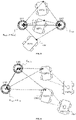
- FIG 5 an embodiment of the method according to the invention is shown, with a moving vehicle (V) passing two static landmarks (LM1, LM2) and at 3 different positions (P1, P2, P3) the localization of the vehicle (V) by an unknown localization system according to previous description, validated by distance measurement.
- the determined distance (D) between the two static landmarks (LM1, LM2) should be essentially unchanged at all 3 positions (P1, P2, P3).
- a substantially unchanged distance (D) between the two static landmarks (LM1, LM2) in the sense of this exemplary embodiment can be expressed on the one hand by a distance (D) that does not exceed a maximum error limit in all 3 measurements and/or on the other hand does not stand out disproportionately within direct comparisons of two measurements each.
- the inner circle in each case schematically forms the known measurement error E TSLMi and the outer circle the resulting error of the unknown localization system, which essentially consists of the error E TGZV of the transformation TGZV, between the coordinate origin (GZ) and the vehicle (V), exists and mathematically can also contain the error E TVS of the transformation TVS between the reference point of the vehicle (V) and the position of the at least one optical sensor (OS) within the vehicle.
- a vehicle (V) is localized indirectly by observing the dynamic environment, preferably moving vehicles (V1, V2), in particular within a vehicle fleet.
- Systems that monitor the dynamic environment of a vehicle (V) can be validated in an advantageous manner.
- a first vehicle (V1) includes a localization system, with the movement of dynamic objects in the environment being detected by means of vehicle-internal sensors (10).
- the corresponding technical means of the vehicle-internal sensors (10) of the first vehicle (V1) can be set up to detect the dynamic environment of the vehicle (V2) and in this way to avoid collisions, for example.
- the method according to the invention can be used to validate a corresponding localization system.
- the first vehicle (V1) comprises at least one first vehicle-internal sensor (OS1) as part of its in-vehicle sensor system (10), which is set up to detect the position of the dynamic environment.
- the at least one first sensor (OS1) can be a camera that is set up to capture moving objects within the viewing angle and to further process this information.
- the first vehicle (V1) detects the movement of a second vehicle (V2) and determines the position of the second vehicle (V2) using a corresponding localization system.
- the position of the second vehicle (V2) can be both relative to the first vehicle (V1) and also in absolute terms within a global coordinate system (GCS), provided that the absolute position of the first vehicle (V1) is also known.
- GCS global coordinate system
- the first vehicle (V1) can, for example, locate the second vehicle (V2) in a first position (P1) at a first time and in a second position (P2) at a second time. If the accuracy with which the localization of the second vehicle (V2) is to be checked by the localization system of the first vehicle (V1) using the camera as a first sensor (OS1), it is necessary for the second vehicle (V2 ) also has at least one sensor (OS2) as part of an in-vehicle sensor system (10) in order to carry out the method according to the invention.
- the second vehicle (V2) carries out the method according to the invention using a sensor (OS2), in which it evaluates the change in the distance between the two static landmarks (LM1, LM2), for example.
- OS2 sensor
- the information from two vehicles is advantageously combined (V1, V2) according to the invention, localization being performed by the first vehicle (V1) and the static environment being measured by the second vehicle (V2).
- the position of the first vehicle (V1) can be determined by an unknown localization system.
- the validation of this localization can be improved in a simple way, simply by arranging a further sensor (OS1), for example in the form of a camera, on the first vehicle (V1), with a second vehicle (V2) using a sensor (OS2 ) captures the static environment of the second vehicle (V2) and transmits this information to the first vehicle (V1) or to an externally stored validation module (32). Due to the known measurement error of the sensor (OS1) of the first vehicle (V1), the information regarding the change in the static environment detected by the second vehicle (V2) can be included in the validation.
- a camera system can be checked as an optical sensor (OS1) of the first vehicle, insofar as it can be validated to what extent the camera system determines the exact position of the observed vehicle (V2).
- the position of the second vehicle (V2) can be determined by an unknown localization system. This unknown localization system can also be validated by combining the available information, with the position of the second vehicle (V2) determined by the first vehicle (V1) using a first sensor (OS1) being combined with the detection of the static surroundings of the second vehicle ( V2) are coupled by a second sensor (OS2).
Landscapes
- Engineering & Computer Science (AREA)
- Radar, Positioning & Navigation (AREA)
- Remote Sensing (AREA)
- Physics & Mathematics (AREA)
- General Physics & Mathematics (AREA)
- Computer Networks & Wireless Communication (AREA)
- Electromagnetism (AREA)
- Automation & Control Theory (AREA)
- General Health & Medical Sciences (AREA)
- Human Computer Interaction (AREA)
- Audiology, Speech & Language Pathology (AREA)
- Artificial Intelligence (AREA)
- Acoustics & Sound (AREA)
- Health & Medical Sciences (AREA)
- Multimedia (AREA)
- Theoretical Computer Science (AREA)
- Navigation (AREA)
- Traffic Control Systems (AREA)
Applications Claiming Priority (1)
| Application Number | Priority Date | Filing Date | Title |
|---|---|---|---|
| DE102020132397.2A DE102020132397A1 (de) | 2020-12-07 | 2020-12-07 | Verfahren, Steuergerät und Fahrzeug zur Validierung der Lokalisierung eines Fahrzeuges durch Referenzierung zu statischen Objekten im Umfeld |
Publications (1)
| Publication Number | Publication Date |
|---|---|
| EP4009072A1 true EP4009072A1 (fr) | 2022-06-08 |
Family
ID=78824969
Family Applications (1)
| Application Number | Title | Priority Date | Filing Date |
|---|---|---|---|
| EP21212923.3A Withdrawn EP4009072A1 (fr) | 2020-12-07 | 2021-12-07 | Procédé, appareil de commande et véhicule destinés à la validation de la localisation d'un véhicule par référencement à des objets statiques dans la zone environnante |
Country Status (2)
| Country | Link |
|---|---|
| EP (1) | EP4009072A1 (fr) |
| DE (1) | DE102020132397A1 (fr) |
Cited By (1)
| Publication number | Priority date | Publication date | Assignee | Title |
|---|---|---|---|---|
| CN118707499A (zh) * | 2024-06-20 | 2024-09-27 | 奇瑞汽车股份有限公司 | 一种车辆高精定位性能测试方法及系统 |
Citations (6)
| Publication number | Priority date | Publication date | Assignee | Title |
|---|---|---|---|---|
| EP0635773A2 (fr) * | 1993-07-21 | 1995-01-25 | Siemens Aktiengesellschaft | Procédé d'établissement d'une carte de l'environnement et de détermination d'une position dans l'environnement au moyen d'un appareil automoteur |
| US20190271550A1 (en) * | 2016-07-21 | 2019-09-05 | Intelligent Technologies International, Inc. | System and Method for Creating, Updating, and Using Maps Generated by Probe Vehicles |
| DE102018212133A1 (de) | 2018-07-20 | 2020-01-23 | Continental Automotive Gmbh | Verfahren und Vorrichtung zur Genauigkeitssteigerung einer Ortsbestimmung |
| EP3643016A1 (fr) | 2017-06-20 | 2020-04-29 | Cisco Technology, Inc. | Sélection de trajet de réseau |
| DE102018218492A1 (de) | 2018-10-29 | 2020-04-30 | Robert Bosch Gmbh | Steuergerät, Verfahren und Sensoranordnung zur selbstüberwachten Lokalisierung |
| US20200310460A1 (en) | 2019-03-28 | 2020-10-01 | Wipro Limited | System and method for validating readings of orientation sensor mounted on autonomous ground vehicle |
Family Cites Families (1)
| Publication number | Priority date | Publication date | Assignee | Title |
|---|---|---|---|---|
| US8447519B2 (en) | 2010-11-10 | 2013-05-21 | GM Global Technology Operations LLC | Method of augmenting GPS or GPS/sensor vehicle positioning using additional in-vehicle vision sensors |
-
2020
- 2020-12-07 DE DE102020132397.2A patent/DE102020132397A1/de active Pending
-
2021
- 2021-12-07 EP EP21212923.3A patent/EP4009072A1/fr not_active Withdrawn
Patent Citations (6)
| Publication number | Priority date | Publication date | Assignee | Title |
|---|---|---|---|---|
| EP0635773A2 (fr) * | 1993-07-21 | 1995-01-25 | Siemens Aktiengesellschaft | Procédé d'établissement d'une carte de l'environnement et de détermination d'une position dans l'environnement au moyen d'un appareil automoteur |
| US20190271550A1 (en) * | 2016-07-21 | 2019-09-05 | Intelligent Technologies International, Inc. | System and Method for Creating, Updating, and Using Maps Generated by Probe Vehicles |
| EP3643016A1 (fr) | 2017-06-20 | 2020-04-29 | Cisco Technology, Inc. | Sélection de trajet de réseau |
| DE102018212133A1 (de) | 2018-07-20 | 2020-01-23 | Continental Automotive Gmbh | Verfahren und Vorrichtung zur Genauigkeitssteigerung einer Ortsbestimmung |
| DE102018218492A1 (de) | 2018-10-29 | 2020-04-30 | Robert Bosch Gmbh | Steuergerät, Verfahren und Sensoranordnung zur selbstüberwachten Lokalisierung |
| US20200310460A1 (en) | 2019-03-28 | 2020-10-01 | Wipro Limited | System and method for validating readings of orientation sensor mounted on autonomous ground vehicle |
Cited By (1)
| Publication number | Priority date | Publication date | Assignee | Title |
|---|---|---|---|---|
| CN118707499A (zh) * | 2024-06-20 | 2024-09-27 | 奇瑞汽车股份有限公司 | 一种车辆高精定位性能测试方法及系统 |
Also Published As
| Publication number | Publication date |
|---|---|
| DE102020132397A1 (de) | 2022-06-09 |
Similar Documents
| Publication | Publication Date | Title |
|---|---|---|
| DE102015214338B4 (de) | Bestimmung einer Anordnungsinformation für ein Fahrzeug | |
| EP3001137B1 (fr) | Procede de surveillance d'un etalonnage de plusieurs capteurs d'environnement d'un vehicule automobile et vehicule automobile | |
| EP3577420B1 (fr) | Procédé de mise a jour d'une carte numérique | |
| EP3649519B1 (fr) | Procédé pour faire vérifier la carte numérique d'un véhicule très automatisé, dispositif correspondant et programme d'ordinateur | |
| DE102020105639A1 (de) | Vorrichtung und Verfahren zum Schätzen einer Position in einem automatisierten Parkdienstsystem | |
| WO2020216559A1 (fr) | Procédé de reconnaissance d'un bon fonctionnement d'un capteur d'environnement, appareil de commande et véhicule | |
| DE102018115813A1 (de) | Verfahren und systeme zum lokalisieren eines fahrzeugs | |
| EP3465088B1 (fr) | Procédé, dispositif et support d'informations lisible par ordinateur comprenant des instructions pour déterminer la position latérale d'un véhicule par rapport aux bandes de circulation d'une chaussée | |
| DE102015206605A1 (de) | Kalibrierung und Überwachung von Umfeldsensoren mit Hilfe hochgenauer Karten | |
| DE102016224329A1 (de) | Verfahren und System zur Lokalisierung eines Fahrzeugs | |
| WO2019063266A1 (fr) | Procédé de localisation d'un véhicule très automatisé (vta), en particulier un véhicule fortement automatisé, et système de véhicule | |
| DE102016223422A1 (de) | Verfahren zur automatischen Ermittlung extrinsischer Parameter einer Kamera eines Fahrzeugs | |
| EP3649794B1 (fr) | Procédé, système d'aide à la conduite et programme pour faire vérifier la carte numérique d'un véhicule très automatisé, en particulier d'un véhicule fortement automatisé | |
| DE102010007091A1 (de) | Verfahren zur Positionsermittlung für ein Kraftfahrzeug | |
| DE102021204372A1 (de) | Orientierungsbasierte Positionsermittlung von Schienenfahrzeugen | |
| EP4165370B1 (fr) | Procédé d'évaluation d'une carte numérique et système d'évaluation | |
| DE102016003261A1 (de) | Verfahren zur Selbstlokalisierung eines Fahrzeugs in einer Fahrzeugumgebung | |
| EP4222451A1 (fr) | Procédé d'essai de plausibilité de cartes | |
| WO2019068827A1 (fr) | Procédé permettant de faire fonctionner un système de navigation | |
| DE102015225577A1 (de) | Verbessertes Verfahren zum Ermitteln der Randbebauung einer Fahrbahn für die Lokalisierung von Kraftfahrzeugen | |
| DE102019208788A1 (de) | Kraftfahrzeug | |
| DE102018007960A1 (de) | Verfahren zum Abgleich von Kartenmaterial mit einer erfassten Umgebung eines Fahrzeugs, Steuergerät, eingerichtet zum Ausführen eines solchen Verfahrens, sowie Fahrzeug mit einem solchen Steuergerät | |
| DE102022112395A1 (de) | Von kreuzungsknoten unterstützte hochauflösende kartierung | |
| DE112022002019T5 (de) | Fahrvorrichtung, fahrzeug und verfahren zum automatisierten fahren und/oder assistierten fahren | |
| DE102017118078A1 (de) | Lokalisationseinrichtung für ein Kraftfahrzeug, Fahrerassistenzeinrichtung, Kraftfahrzeug sowie Verfahren zum Lokalisieren eines Kraftfahrzeugs |
Legal Events
| Date | Code | Title | Description |
|---|---|---|---|
| PUAI | Public reference made under article 153(3) epc to a published international application that has entered the european phase |
Free format text: ORIGINAL CODE: 0009012 |
|
| STAA | Information on the status of an ep patent application or granted ep patent |
Free format text: STATUS: THE APPLICATION HAS BEEN PUBLISHED |
|
| AK | Designated contracting states |
Kind code of ref document: A1 Designated state(s): AL AT BE BG CH CY CZ DE DK EE ES FI FR GB GR HR HU IE IS IT LI LT LU LV MC MK MT NL NO PL PT RO RS SE SI SK SM TR |
|
| STAA | Information on the status of an ep patent application or granted ep patent |
Free format text: STATUS: THE APPLICATION IS DEEMED TO BE WITHDRAWN |
|
| 18D | Application deemed to be withdrawn |
Effective date: 20221209 |