EP4009073A1 - Vorrichtung zur entfernungsbildaufnahme und verfahren zur entfernungsbildaufnahme - Google Patents
Vorrichtung zur entfernungsbildaufnahme und verfahren zur entfernungsbildaufnahme Download PDFInfo
- Publication number
- EP4009073A1 EP4009073A1 EP20847013.8A EP20847013A EP4009073A1 EP 4009073 A1 EP4009073 A1 EP 4009073A1 EP 20847013 A EP20847013 A EP 20847013A EP 4009073 A1 EP4009073 A1 EP 4009073A1
- Authority
- EP
- European Patent Office
- Prior art keywords
- electric charge
- distance
- light
- charge accumulating
- unit
- Prior art date
- Legal status (The legal status is an assumption and is not a legal conclusion. Google has not performed a legal analysis and makes no representation as to the accuracy of the status listed.)
- Pending
Links
Images





Classifications
-
- H—ELECTRICITY
- H04—ELECTRIC COMMUNICATION TECHNIQUE
- H04N—PICTORIAL COMMUNICATION, e.g. TELEVISION
- H04N23/00—Cameras or camera modules comprising electronic image sensors; Control thereof
- H04N23/70—Circuitry for compensating brightness variation in the scene
-
- G—PHYSICS
- G01—MEASURING; TESTING
- G01S—RADIO DIRECTION-FINDING; RADIO NAVIGATION; DETERMINING DISTANCE OR VELOCITY BY USE OF RADIO WAVES; LOCATING OR PRESENCE-DETECTING BY USE OF THE REFLECTION OR RERADIATION OF RADIO WAVES; ANALOGOUS ARRANGEMENTS USING OTHER WAVES
- G01S17/00—Systems using the reflection or reradiation of electromagnetic waves other than radio waves, e.g. lidar systems
- G01S17/88—Lidar systems specially adapted for specific applications
- G01S17/89—Lidar systems specially adapted for specific applications for mapping or imaging
- G01S17/894—Three-dimensional [3D] imaging with simultaneous measurement of time-of-flight at a two-dimensional [2D] array of receiver pixels, e.g. time-of-flight cameras or flash lidar
-
- G—PHYSICS
- G01—MEASURING; TESTING
- G01S—RADIO DIRECTION-FINDING; RADIO NAVIGATION; DETERMINING DISTANCE OR VELOCITY BY USE OF RADIO WAVES; LOCATING OR PRESENCE-DETECTING BY USE OF THE REFLECTION OR RERADIATION OF RADIO WAVES; ANALOGOUS ARRANGEMENTS USING OTHER WAVES
- G01S17/00—Systems using the reflection or reradiation of electromagnetic waves other than radio waves, e.g. lidar systems
- G01S17/02—Systems using the reflection of electromagnetic waves other than radio waves
- G01S17/06—Systems determining position data of a target
- G01S17/08—Systems determining position data of a target for measuring distance only
-
- G—PHYSICS
- G01—MEASURING; TESTING
- G01S—RADIO DIRECTION-FINDING; RADIO NAVIGATION; DETERMINING DISTANCE OR VELOCITY BY USE OF RADIO WAVES; LOCATING OR PRESENCE-DETECTING BY USE OF THE REFLECTION OR RERADIATION OF RADIO WAVES; ANALOGOUS ARRANGEMENTS USING OTHER WAVES
- G01S17/00—Systems using the reflection or reradiation of electromagnetic waves other than radio waves, e.g. lidar systems
- G01S17/02—Systems using the reflection of electromagnetic waves other than radio waves
- G01S17/06—Systems determining position data of a target
- G01S17/08—Systems determining position data of a target for measuring distance only
- G01S17/10—Systems determining position data of a target for measuring distance only using transmission of interrupted, pulse-modulated waves
-
- G—PHYSICS
- G01—MEASURING; TESTING
- G01S—RADIO DIRECTION-FINDING; RADIO NAVIGATION; DETERMINING DISTANCE OR VELOCITY BY USE OF RADIO WAVES; LOCATING OR PRESENCE-DETECTING BY USE OF THE REFLECTION OR RERADIATION OF RADIO WAVES; ANALOGOUS ARRANGEMENTS USING OTHER WAVES
- G01S7/00—Details of systems according to groups G01S13/00, G01S15/00, G01S17/00
- G01S7/48—Details of systems according to groups G01S13/00, G01S15/00, G01S17/00 of systems according to group G01S17/00
- G01S7/483—Details of pulse systems
- G01S7/486—Receivers
- G01S7/4861—Circuits for detection, sampling, integration or read-out
- G01S7/4863—Detector arrays, e.g. charge-transfer gates
-
- G—PHYSICS
- G01—MEASURING; TESTING
- G01S—RADIO DIRECTION-FINDING; RADIO NAVIGATION; DETERMINING DISTANCE OR VELOCITY BY USE OF RADIO WAVES; LOCATING OR PRESENCE-DETECTING BY USE OF THE REFLECTION OR RERADIATION OF RADIO WAVES; ANALOGOUS ARRANGEMENTS USING OTHER WAVES
- G01S7/00—Details of systems according to groups G01S13/00, G01S15/00, G01S17/00
- G01S7/48—Details of systems according to groups G01S13/00, G01S15/00, G01S17/00 of systems according to group G01S17/00
- G01S7/483—Details of pulse systems
- G01S7/486—Receivers
- G01S7/4865—Time delay measurement, e.g. time-of-flight measurement, time of arrival measurement or determining the exact position of a peak
-
- H—ELECTRICITY
- H04—ELECTRIC COMMUNICATION TECHNIQUE
- H04N—PICTORIAL COMMUNICATION, e.g. TELEVISION
- H04N23/00—Cameras or camera modules comprising electronic image sensors; Control thereof
- H04N23/56—Cameras or camera modules comprising electronic image sensors; Control thereof provided with illuminating means
-
- H—ELECTRICITY
- H04—ELECTRIC COMMUNICATION TECHNIQUE
- H04N—PICTORIAL COMMUNICATION, e.g. TELEVISION
- H04N23/00—Cameras or camera modules comprising electronic image sensors; Control thereof
- H04N23/70—Circuitry for compensating brightness variation in the scene
- H04N23/72—Combination of two or more compensation controls
-
- H—ELECTRICITY
- H04—ELECTRIC COMMUNICATION TECHNIQUE
- H04N—PICTORIAL COMMUNICATION, e.g. TELEVISION
- H04N25/00—Circuitry of solid-state image sensors [SSIS]; Control thereof
- H04N25/50—Control of the SSIS exposure
- H04N25/53—Control of the integration time
- H04N25/531—Control of the integration time by controlling rolling shutters in CMOS SSIS
-
- H—ELECTRICITY
- H04—ELECTRIC COMMUNICATION TECHNIQUE
- H04N—PICTORIAL COMMUNICATION, e.g. TELEVISION
- H04N25/00—Circuitry of solid-state image sensors [SSIS]; Control thereof
- H04N25/70—SSIS architectures; Circuits associated therewith
- H04N25/76—Addressed sensors, e.g. MOS or CMOS sensors
- H04N25/77—Pixel circuitry, e.g. memories, A/D converters, pixel amplifiers, shared circuits or shared components
- H04N25/771—Pixel circuitry, e.g. memories, A/D converters, pixel amplifiers, shared circuits or shared components comprising storage means other than floating diffusion
Definitions
- the present invention relates to a distance-image capturing apparatus and a distance-image capturing method.
- distance-image capturing apparatuses of a time of flight (hereinafter, referred to as "TOF") system measuring the distance to a subject on the basis of a flying time of light using a fact that the speed of light is known are known.
- TOF time of flight
- a distance-image capturing apparatus similar to an image capturing apparatus, a plurality of pixels detecting light for measuring a distance are disposed in a two-dimensional matrix pattern, and information of a two-dimensional distance to a subject and an image of the subject can be obtained (captured).
- a flare phenomenon When reflected light with such a high intensity is received, multiple reflections, a so-called a flare phenomenon, occurs in an optical system such as a lens inside a distance-image capturing apparatus.
- This flare phenomenon has an influence on the amount of received light of pixels detecting light for measuring the distance to an object that is present at a long distance and becomes a factor causing error in the measured distance.
- the flare phenomenon can be reduced or avoided.
- processing that is specific to a lens is necessary, and there is a problem that the costs may rise, or the measurement environment may be restricted.
- Patent Document 1 a technology for eliminating a light reception component according to a flare phenomenon using a database of a reference electric charge amount ratio is disclosed.
- the reference electric charge amount ratio is the ratio of the amount of electric charge for each distance that is obtained by measuring a target object in an ideal environment of a case in which flare does not occur.
- Patent Document 1 Japanese Patent No. 6298236
- the present invention is based on the problem described above, and an object thereof is to provide a distance-image capturing apparatus and a distance-image capturing method capable of inhibiting an influence according to a flare phenomenon without changing an optical configuration of the inside of the apparatus and without generating a database indicating a relation between a distance and a ratio of amounts of electric charge in an ideal environment.
- a distance-image capturing apparatus including: a light source unit that emits a light pulse to a measurement space that is a space in which measurement is performed; a light receiving unit that includes pixels each including a photoelectric conversion device generating electric charge according to incident light and a plurality of electric charge accumulating units accumulating the electric charge and a pixel driving circuit that distributes the electric charge to the electric charge accumulating units of the pixels to be accumulated in the electric charge accumulating units at a predetermined accumulation timing synchronized with the emission of the light pulse; and a distance image processing unit that measures the distance to a subject present in the measurement space on the basis of amounts of electric charge accumulated in the electric charge accumulating units, the distance image processing unit including a timing control unit that controls the accumulation timing in accordance with a measurement mode set in advance in accordance with the range of distances that are measurement targets.
- the plurality of electric charge accumulating units of the pixel may be formed from a first electric charge accumulating unit, a second electric charge accumulating unit, and a third electric charge accumulating unit, and in a case in which the measurement mode is a long-distance mode, the timing control unit may accumulate the electric charge in the first electric charge accumulating unit in an external light accumulation period that is an off state in which the light pulse is not emitted, set at least a flare light reception period as a non-accumulation period in which the electric charge is not accumulated in any one of the electric charge accumulating units, and, after elapse of the non-accumulation period, distribute electric charge corresponding to an amount of light incident to the light receiving unit in a reflected light reception period to the second electric charge accumulating unit and the third electric charge accumulating unit to be accumulated in the second electric charge accumulating unit and the third electric charge accumulating unit, the flare light reception period being a period that is delayed by a
- the timing control unit performs measurement in the intermediate distance mode and an intermediate distance external light mode as the measurement modes and, in a case in which the measurement mode is the intermediate distance external light mode, accumulates the electric charge in the first electric charge accumulating unit in an external light accumulation period that is an off state in which the light pulse is not emitted, and the distance image processing unit extracts a flare light component according to flare light on the basis of the amounts of electric charge accumulated in the electric charge accumulating units in the intermediate distance mode, extracts an external light component according to external light on the basis of the amounts of electric charge accumulated in the electric charge accumulating units in the intermediate distance external light mode, and measures the distance to the subject using the extracted flare light component and the external light component.
- the timing control unit accumulates the electric charge in the first electric charge accumulating unit in the external light accumulation period in which the light pulse is the off state, sets the flare light reception period as a non-accumulation period in which the electric charge is not accumulated in any one of the electric charge accumulating unit, and distributes an electric charge corresponding to the amount of light incident to the light receiving unit in a reflected light reception period to the second electric charge accumulating unit and the third electric charge accumulating unit to be accumulated in the second electric charge accumulating unit and the third electric charge accumulating unit, and the distance image processing unit measures the distance to the subject present in the measurement space by combining the amounts of electric charge accumulated in the electric charge accumulating units in the intermediate distance mode and the amounts of electric charge accumulated in the electric charge accumulating units in the intermediate distance external light mode.
- the distance image processing unit extracts values acquired by multiplying the amount of electric charge accumulated in the first electric charge accumulating unit by a constant in the intermediate distance mode as a flare light component according to flare light included in the amount of electric charge accumulated in the second electric charge accumulating unit.
- the plurality of electric charge accumulating units of the pixel are formed from a first electric charge accumulating unit, a second electric charge accumulating unit, a third electric charge accumulating unit, and a fourth electric charge accumulating unit
- the timing control unit accumulates the electric charge in the first electric charge accumulating unit in an external light accumulation period that is an off state in which the light pulse is not emitted, distributes an electric charge corresponding to an amount of light incident to the light receiving unit to the second electric charge accumulating unit and the third electric charge accumulating unit to be accumulated in the second electric charge accumulating unit and the third electric charge accumulating unit in a flare light reception period, and distributes an electric charge corresponding to an amount of light incident to the light receiving unit in a reflected light reception period to the third electric charge accumulating unit and the fourth electric charge accumulating unit to be accumulated in the third electric charge accumulating unit and the fourth electric charge accumulating unit
- the flare light reception period is a period
- the distance-image capturing apparatus further including a measurement control unit that controls measurement, in which the measurement control unit causes the distance to the subject to be measured with the measurement mode set as a first normal mode, determines whether or not a short distance object present at a shorter distance than the subject is present in the measurement space on the basis of the amounts of electric charge accumulated in the electric charge accumulating units in the first normal mode, and, in a case in which the short distance object is present in the measurement space, changes the measurement mode and performs re-measurement, and the plurality of electric charge accumulating units of the pixel are formed from a first electric charge accumulating unit, a second electric charge accumulating unit, and a third electric charge accumulating unit, and in a case in which the measurement mode is the first normal mode, the timing control unit accumulates the electric charge in the first electric charge accumulating unit in an external light accumulation period that is an off state in which the light pulse is not emitted and repeats an accumulation period in which the electric charge is sequentially accumulated in the
- the measurement control unit determines that the short distance object is present in the measurement space.
- a distance-image capturing method using a distance-image capturing apparatus including: a light source unit that emits a light pulse to a measurement space that is a space in which measurement is performed; a light receiving unit that includes pixels each including a photoelectric conversion device generating electric charge according to incident light and a plurality of electric charge accumulating units accumulating the electric charge and a pixel driving circuit that distributes the electric charge to the electric charge accumulating units of the pixels to be accumulated in the electric charge accumulating units at a predetermined accumulation timing synchronized with the emission of the light pulse; a distance image processing unit that measures the distance to a subject present in the measurement space on the basis of amounts of electric charge accumulated in the electric charge accumulating units; and a timing control unit that controls the accumulation timing, the distance-image capturing method including a step of controlling the accumulation timing in accordance with a measurement mode set in advance in accordance with the range of distances that are measurement targets using the timing control unit.
- an effect according to a flare phenomenon can be inhibited without changing an optical configuration of the inside of an apparatus and without using a database.
- Fig. 1 is a block diagram showing a schematic configuration of a distance-image capturing apparatus according to the first embodiment of the present invention.
- the distance-image capturing apparatus 1 having the configuration illustrated in Fig. 1 includes a light source unit 2, a light receiving unit 3, and a distance image processing unit 4.
- a subject S that is a target object for which a distance is measured by the distance-image capturing apparatus 1 is shown in Fig. 1 as well.
- the light source unit 2 emits a light pulse PO to an imaging target space in which the subject S that is a target, for which a distance is measured by the distance-image capturing apparatus 1 is present, in accordance with control from the distance image processing unit 4.
- the light source unit 2 for example, is a semiconductor laser module of a surface emission type such as a vertical cavity surface emitting laser (VCSEL).
- the light source unit 2 includes a light source device 21 and a diffusion plate 22
- the light source device 21 is a light source that emits laser light having a near infrared wavelength band (for example, the wavelength is in a wavelength band of 850 nm to 940 nm) that becomes a light pulse PO emitted to a subject S.
- the light source device 21, for example, is a semiconductor laser light emitting device.
- the light source device 21 emits laser light having a pulse shape in accordance with control from a timing control unit 41.
- the diffusion plate 22 is an optical component that diffuses laser light of a near infrared wavelength band emitted by the light source device 21 into an area of a surface of the subject S to which the laser light is emitted. Pulse-shaped laser light diffused by the diffusion plate 22 exits as a light pulse PO and is emitted to a subject S.
- the light receiving unit 3 receives reflected light RL of a light pulse PO reflected by a subject S that is a target for which a distance is measured by the distance-image capturing apparatus 1 and outputs a pixel signal according to the received reflected light RL.
- the light receiving unit 3 includes a lens 31 and a distance image sensor 32.
- the lens 31 is an optical lens that leads reflected light RL that has been incident to the distance image sensor 32.
- the lens 31 causes the incident reflected light RL to exit to the distance image sensor 32 side and be received by (incident to) pixels provided in a light reception area of the distance image sensor 32.
- the distance image sensor 32 is an imaging device used in the distance-image capturing apparatus 1.
- the distance image sensor 32 includes a plurality of pixels in a two-dimensional light reception area.
- One photoelectric conversion device, a plurality of electric charge accumulating units corresponding to one photoelectric conversion device, and a constituent element distributing electric charge to the electric charge accumulating units are disposed in each of the pixels of the distance image sensor 32.
- the pixels are imaging devices having a configuration for distributing and accumulating electric charge in a plurality of electric charge accumulating units.
- the distance image sensor 32 distributes an electric charge generated by photoelectric conversion devices to the electric charge accumulating units in accordance with control from the timing control unit 41. In addition, the distance image sensor 32 outputs a pixel signal corresponding to the amount of electric charge distributed to each electric charge accumulating unit. A plurality of pixels are disposed in a two-dimensional matrix pattern in the distance image sensor 32, and pixel signals corresponding to one frame corresponding to each pixel are output.
- the distance image processing unit 4 calculates the distance to a subject S by controlling the distance-image capturing apparatus 1.
- the distance image processing unit 4 includes a timing control unit 41, a distance calculating unit 42, and a measurement control unit 43.
- the timing control unit 41 controls timings at which various control signals required for measurement are output in accordance with control of the measurement control unit 43.
- the various control signals described here are a signal for controlling emission of a light pulse PO, a signal for distributing reflected light RL into a plurality of electric charge accumulating units, a signal for controlling the number of times of distribution per frame, and the like.
- the number of times of distribution is the number of times of repetition of the process of distributing electric charge to the electric charge accumulating units CS (see Fig. 3 ).
- the distance calculating unit 42 outputs distance information calculated as the distance to a subject S on the basis of pixel signals output from the distance image sensor 32.
- the distance calculating unit 42 calculates a delay time Td (see Fig. 12A ) that is a time from emission of a light pulse PO to receiving of a reflected light RL on the basis of the amounts of electric charge accumulated in the plurality of electric charge accumulating units.
- the distance calculating unit 42 calculates the distance to a subject S in accordance with the calculated delay time Td.
- the measurement control unit 43 selects one measurement mode from among a plurality of measurement modes in accordance with a measurement environment.
- a measurement mode is provided for each environment in which measurement is performed, and a timing at which a light pulse PO is emitted and a timing at which reflected light RL is distributed to the plurality of electric charge accumulating units are defined using different relations.
- the environments in which measurement are performed are classified in accordance with the range of distances to be measured, and whether or not flare light, that is a cause of deterioration in accuracy of measurement, has been taken into consideration or not, and the like. Details of measurement modes will be described in detail later.
- reflected light RL acquired by a light pulse PO of a near infrared wavelength band emitted to a subject S by the light source unit 2 being reflected by the subject S is received by the light receiving unit 3, and the distance image processing unit 4 outputs distance information acquired by measuring the distance to the subject S.
- the distance image processing unit 4 may be a constituent element that is provided outside the distance-image capturing apparatus 1.
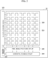
- FIG. 2 is a block diagram showing a schematic configuration of an imaging device (the distance image sensor 32) used in the distance-image capturing apparatus 1 according to the first embodiment of the present invention.
- the distance image sensor 32 includes a light reception area 320 in which a plurality of pixels 321 are disposed, a control circuit 322, a vertical scanning circuit 323 having a distribution operation, a horizontal scanning circuit 324, and a pixel signal processing circuit 325.
- the light reception area 320 is an area in which a plurality of pixels 321 are disposed, and Fig. 2 illustrates an example in which the pixels are disposed in a two-dimensional matrix pattern of eight rows and eight columns.
- the pixels 321 accumulate electric charge corresponding to the amount of received light.
- the control circuit 322 performs overall control of the distance image sensor 32.
- the control circuit 322 controls operations of constituent elements of the distance image sensor 32 in accordance with an instruction from the timing control unit 41 of the distance image processing unit 4.
- the control of the constituent elements included in the distance image sensor 32 may be configured to be directly performed by the timing control unit 41. In such a case, the control circuit 322 may be omitted.
- the vertical scanning circuit 323 is a circuit that controls the pixels 321 disposed in the light reception area 320 for each row in accordance with control from the control circuit 322.
- the vertical scanning circuit 323 outputs a voltage signal according to an amount of electric charge accumulated in each of the electric charge accumulating units CS of the pixel 321 to the pixel signal processing circuit 325.
- the vertical scanning circuit 323 distributes an electric charge converted by the photoelectric conversion device to each of the electric charge accumulating units of the pixel 321.
- the vertical scanning circuit 323 is one example of a "pixel driving circuit".
- the pixel signal processing circuit 325 is a circuit that performs signal processing set in advance (for example, a noise suppression process, an A/D conversion process, or the like) on a voltage signal output to a corresponding vertical signal line from the pixels 321 of each column in accordance with control from the control circuit 322.
- the horizontal scanning circuit 324 is a circuit that sequentially outputs signals output from the pixel signal processing circuit 325 to horizontal signal lines in accordance with control from the control circuit 322. In accordance with this, a pixel signal corresponding to the amount of accumulated electric charge corresponding to one frame is sequentially output to the distance image processing unit 4 through the horizontal signal line.
- pixel signal processing circuit 325 performs an A/D conversion process, and pixel signals are digital signals.
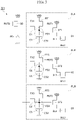
- Fig. 3 is a circuit diagram showing an example of the configuration of the pixel 321 disposed within the light reception area 320 of the imaging device (the distance image sensor 32) used in the distance-image capturing apparatus 1 according to the first embodiment of the present invention.
- Fig. 3 illustrates an example of the configuration of one pixel 321 among a plurality of pixels 321 disposed within the light reception area 320.
- the pixel 321 is an example of the configuration in which three pixel signal reading units are included.
- the pixel 321 includes one photoelectric conversion device PD, a drain gate transistor GD, and three pixel signal reading units RU that output voltage signals from corresponding output terminals O.
- Each of the pixel signal reading units RU includes a reading gate transistor G, a floating diffusion FD, an electric charge accumulating capacitor C, a reset gate transistor RT, a source follower gate transistor SF, and a selection gate transistor SL.
- an electric charge accumulating unit CS is composed of the floating diffusion FD and the electric charge accumulating capacitor C.
- the individual pixel signal reading units RU can be distinguished from each other.
- the pixel signal reading unit RU to which each constituent element corresponds can be represented in a distinguishing manner.
- the pixel signal reading unit RU1 that outputs a voltage signal from an output terminal O1 includes a reading gate transistor G1, a floating diffusion FD1, an electric charge accumulating capacitor C1, a reset gate transistor RT1, a source follower gate transistor SF1, and a selection gate transistor SL1.
- an electric charge accumulating unit CS1 is composed of a floating diffusion FD1 and an electric charge accumulating capacitor C1.
- the pixel signal reading unit RU2 and the pixel signal reading unit RU3 have configurations similar thereto.
- the electric charge accumulating unit CS1 is one example of a "first electric charge accumulating unit”.
- the electric charge accumulating unit CS2 is one example of a "second electric charge accumulating unit”.
- the electric charge accumulating unit CS3 is one example of a "third electric charge accumulating unit”.
- the photoelectric conversion device PD is a photodiode of an embedded type that generates electric charge by performing a photoelectric conversion of incident light and accumulates the generated electric charge.
- the structure of the photoelectric conversion device PD may be arbitrarily selected.
- the photoelectric conversion device PD for example, may be either a PN photo diode having a structure in which a P-type semiconductor and an N-type semiconductor are bonded or a PIN photodiode having a structure in which an I-type semiconductor is interposed between a P-type semiconductor and an N-type semiconductor.
- the photoelectric conversion device PD is not limited to a photodiode and, for example, may be a photoelectric conversion device of a photo-gate type.
- the pixel 321 distributes the electric charge generated by performing a photoelectric conversion of incident light using the photoelectric conversion device PD to the three electric charge accumulating units CS and outputs voltage signals corresponding to the amounts of distributed electric charge to the pixel signal processing circuit 325.
- the configuration of the pixel disposed in the distance image sensor 32 is not limited to the configuration including three pixel signal reading units RU as shown in Fig. 3 , and the pixel may have a configuration in which a plurality of pixel signal reading units RU are included.
- the number of pixel signal reading units RU (electric charge accumulating units CS) included in the pixel disposed in the distance image sensor 32 may be two or four or more.
- the electric charge accumulating unit CS is composed of the floating diffusion FD and the electric charge accumulating capacitor C is shown.
- the electric charge accumulating unit CS may be configured using at least the floating diffusion FD, and a configuration in which the pixel 321 does not include the electric charge accumulating capacitor C may be employed.
- a configuration in which no drain gate transistor GD is included may be employed in a case in which electric charge accumulated (remaining) in the photoelectric conversion device PD does not need to be discarded.
- Fig. 12A is a timing diagram showing timings of drive signals for driving pixels in a conventional distance-image capturing apparatus.
- a timing at which a light pulse PO is emitted, a timing at which reflected light is received, a timing of a drive signal TX1, a timing of a drive signal TX2, a timing of a drive signal TX3, and a timing of a drive signal RSTD are respectively denoted using item names of "Light”, “REFRECTION_B”, "G1", “G2", “G3”, and "GD”.
- a series of timings of a light reception operation in the distance-image capturing apparatus are denoted using an item name "Camera”.
- timings at which reading gate transistors G1, G2, and G3 and a drain gate transistor GD come into an on state are respectively denoted as “G1", “G2", “G3”, and "GD".
- the drive signal TX1 is a signal for driving the reading gate transistor G1. This similarly applies also to the drive signals TX2 and TX3.
- the light pulse PO is emitted for an emission time To, and reflected light RL is received by the distance image sensor 32 with a delay time Td delayed.
- the vertical scanning circuit 323 accumulates electric charge in order of the electric charge accumulating units CS1, CS2, and CS3 in synchronization with the emission of the light pulse PO.
- the vertical scanning circuit 323 causes the reading gate transistor G1 to be the on state. In accordance with this, electric charge acquired through photoelectric conversion using the photoelectric conversion device PD is accumulated in the electric charge accumulating unit CS1 through the reading gate transistor G1. Thereafter, the vertical scanning circuit 323 causes the reading gate transistor G1 to be an off state. In accordance with this, transmission of electric charge to the electric charge accumulating unit CS1 stops. In this way, the vertical scanning circuit 323 accumulates electric charge in the electric charge accumulating unit CS1.
- the vertical scanning circuit 323 causes the reading gate transistor G2 to be the on state at the timing at which accumulation of electric charge in the electric charge accumulating unit CS1 ends and starts accumulation of electric charge in the electric charge accumulating unit CS2. Thereafter, a flow of the process of accumulating electric charge in the electric charge accumulating unit CS2 is similar to the flow of the process of accumulating electric charge in the electric charge accumulating unit CS1, and thus a description thereof will be omitted.
- the light source unit 2 emits a light pulse PO at a timing at which the reading gate transistor G1 comes into the off state, in other words, a timing at which the reading gate transistor G2 comes into the on state.
- An emission time To for which the light source unit 2 emits the light pulse PO has the same length as an accumulation period Ta.
- a period (an accumulation period Ta) in which the reading gate transistor G1 comes into the on state, and electric charge is accumulated in the electric charge accumulating unit CS1 is one example of an "external light accumulation period".
- the vertical scanning circuit 323 causes the reading gate transistor G3 to be the on state at the timing at which accumulation of electric charge in the electric charge accumulating unit CS2 ends and starts accumulation of electric charge in the electric charge accumulating unit CS3. Thereafter, a flow of the process of accumulating electric charge in the electric charge accumulating unit CS3 is similar to the flow of the process of accumulating electric charge in the electric charge accumulating unit CS1, and thus a description thereof will be omitted.
- the vertical scanning circuit 323 causes the drain gate transistor GD to come into the on state at the timing at which accumulation of electric charge in the electric charge accumulating unit CS3 ends and discharges electric charge. In accordance with this, electric charge acquired through photoelectric conversion using the photoelectric conversion device PD is discarded through the drain gate transistor GD.
- the accumulation of electric charge in the electric charge accumulating unit CS using the vertical scanning circuit 323 and the discarding of electric charge acquired through photoelectric conversion performed by the photoelectric conversion device PD as described above are repeatedly performed at another frame.
- electric charge corresponding to the amount of light received by the distance-image capturing apparatus 1 in a predetermined time section is accumulated in each electric charge accumulating units CS.
- the horizontal scanning circuit 324 outputs an electric signal corresponding to the amount of electric charge corresponding to one frame, which is accumulated in each electric charge accumulating unit CS, to the distance calculating unit 42.
- a proportion (a distribution ratio) of electric charge distributed in the electric charge accumulating units CS2 and CS3 is a ratio according to the delay time Td until the light pulse PO is reflected on a subject S and is incident to the distance-image capturing apparatus 1.
- the distance calculating unit 42 calculates the delay time Td using the following Equation (1) using this principle.
- Td To ⁇ Q 3 ⁇ Q 1 / Q 2 + Q 3 ⁇ 2 ⁇ Q 1
- Equation (1) it is premised that a component corresponding to an external light component among amounts of electric charge accumulated in the electric charge accumulating units CS2 and CS3 is the same as the amount of electric charge accumulated in the electric charge accumulating unit CS1.
- the distance calculating unit 42 calculates a reciprocation distance to the subject S. Then, by calculating 1/2 of the reciprocation distance calculated as described above, the distance calculating unit 42 acquires the distance to the subject S.
- Fig. 12B is a diagram showing a concept of flare light.
- a case in which an object B present at a position of which a distance from the distance-image capturing apparatus 1 is relatively long (hereinafter, referred to as being present at a long distance or the like) in a measurement space E that is a measurement target to which the light pulse PO can be emitted is a subject will be considered.
- the amount of the reflected light RL is smaller than in a case in which an object present at a position of which a distance from the distance-image capturing apparatus 1 is relatively short is measured.
- the amount of the reflected light RL is small, it may be a factor for degrading accuracy of a measured distance. For this reason, in a case in which the distance to a subject is a long distance, it may be considered to improve the accuracy of measurement by increasing the amount of exposure (the amount of light received by the distance image sensor 32) by increasing the number of times of distribution.
- a part of received light is multi-reflected inside the distance-image capturing apparatus 1 when the part of light arrives at the distance image sensor 32 through the lens 31.
- light is received at a position different from a position at which reflected light from an object is originally imaged.
- flare light may be a factor degrading the accuracy of measurement.
- Fig. 12C is a diagram showing a case in which flare light is received in conventional measurement.
- "FLARE_A” shown in Fig. 12C represents flare light originated from reflected light from an object A or the like (an object present at a short distance).
- "REFRECTION_B” represents reflected light from an object B (a subject present at a long distance).
- items such as "Light” and the like are similar to those shown in Fig. 12A , and thus a description thereof will be omitted.
- a light pulse PO is emitted for an emission time To, and flare light with a delay time Tb and reflected light RL with a delay time Td are received by the distance image sensor 32.
- an amount of electric charge corresponding to the flare light is accumulated in the electric charge accumulating units CS2 and CS3 in addition to amounts of electric charge corresponding to reflected light RL and an external light component.
- Equation (1) Even by applying Equation (1) to the amount of electric charge according to flare light being mixed, it is difficult to calculate a distance with high accuracy.
- a plurality of measurement modes are defined in this embodiment.
- the measurement modes timings at which electric charge is distributed to electric charge accumulating units with respect to an emission timing of the light pulse PO are set to different timings.
- the measurement modes are defined in accordance with ranges of distances that are measurement targets.
- the ranges of distances that are measurement targets are divided in accordance with a distance calculated in accordance with a delay time Td until reception of reflected light RL after emission of the light pulse PO.
- the ranges of distances are three ranges including a long distance, an intermediate distance, and a short distance that are divided in accordance with a distance from the distance-image capturing apparatus 1.
- the short distance is a range of about 0 to 75 cm
- the intermediate distance is a range of about 75 cm to 2.25 m
- the long distance is a range equal to or larger than about 2.25 m.
- the measurement modes are defined in accordance with whether or not a countermeasure for inhibiting occurrence of flare light (hereinafter, referred to as a countermeasure for flare light) is taken.
- a countermeasure for flare light In a case in which an object other than a subject is present at a short distance, a countermeasure for inhibiting occurrence of flare light is taken. On the other hand, in a case in which an object other than a subject is not present at a short distance, a countermeasure for flare light is not taken.
- a long-distance mode for example, a long-distance mode, an intermediate distance mode, an intermediate distance mode, an intermediate distance external light mode, a normal mode 1 (a first normal mode), and a normal mode 2 (a second normal mode) are defined.
- the long-distance mode is a mode in which the distance to a subject may be present at a long distance is measured with high accuracy in a situation in which an object other than the subject is present at a short distance.
- the long-distance mode is a mode in which a subject present at a long distance is measured with a countermeasure for flare light taken.
- the intermediate distance mode is a mode in which the distance to a subject present at an intermediate distance is measured with high accuracy in a situation in which an object other than the subject may be present at a short distance.
- the intermediate distance mode is a mode in which a subject present at an intermediate distance is measured with a countermeasure for flare light is taken.
- the intermediate distance external light mode is a mode in which an amount of electric charge corresponding to external light is measured at the time of performing measurement in the intermediate distance mode.
- the intermediate distance external light mode is a mode used in a case in which external light is taken into account at the time of performing measurement in the intermediate distance mode.
- the normal mode 1 is a mode in which the distance to a subject present at a long distance is measured in a situation in which an object other than the subject is assumed not to be present at a short distance.
- the normal mode 1 is a mode in which a subject present at a long distance is measured with a countermeasure for flare light not taken.
- the normal mode 1 is a mode in which conventional measurement is performed.
- the normal mode 2 is a mode in which the distance to an object present at a short distance is measured.
- the normal mode 2 is a mode in which conventional measurement is performed and is a mode in which the amount of exposure is inhibited more than in the normal mode 1 (in other words, the number of times of distribution is decreased).
- the long-distance mode, the intermediate distance mode, and the intermediate distance external light mode will be sequentially described.
- Fig. 4 is a timing diagram showing timings at which pixels 321 are driven in the long-distance mode according to the first embodiment.
- a timing at which the drain gate transistor GD comes into the on state between "G1" and "G2" is denoted as "GD2".
- the other items such as "Light" are similar to those shown in Fig. 12C , and thus a description thereof will be omitted.
- a light pulse PO is emitted for an emission time To, and flare light with a delay time Tb and reflected light RL with a delay time Td are received by the distance image sensor 32.
- the long-distance mode is used in a situation in which an object B that is a subject and an object A that becomes a factor causing an occurrence of flare light are assumed to be at a long distance from the distance-image capturing apparatus 1.
- the long-distance mode is used in a situation in which it is premised that the delay time Td is longer than the delay time Tb, and the flare light and the reflected light RL are not simultaneously received.
- a timing at which a light pulse PO is emitted and a timing at which electric charge is accumulated in the electric charge accumulating unit CS are adjusted such that electric charge originated from flare light is not accumulated.
- the vertical scanning circuit 323 causes the reading gate transistor G1 to be the on state during an accumulation period Ta and accumulates electric charge corresponding to external light in the electric charge accumulating unit CS1.
- the vertical scanning circuit 323 causes the drain gate transistor GD to be the on state.
- electric charge acquired through photoelectric conversion using the photoelectric conversion device PD is discarded (discharged).
- electric charge acquired by performing photoelectric conversion of flare light received while the drain gate transistor GD is the on state is not accumulated in the electric charge accumulating unit CS.
- the vertical scanning circuit 323 sets a period in which at least flare light is received (a flare light reception period) as a period in which electric charge acquired through photoelectric conversion is discarded (discharged), in other words, a "non-accumulation period" in which electric charge is not accumulated.
- the "flare light reception period” and a “reflected light reception period” are periods not overlapping each other.
- the "flare light reception period” is a period until the light pulse emission time To (an emission period) elapses from a time acquired by delaying a time at which the emission of the light pulse PO starts by the delay time Tb.
- the “flare light reception period” is a period acquired by delaying the emission time To of the light pulse PO by the delay time Tb.
- the delay time Tb is one example of a "pulse light delay time”.
- the "reflected light reception period” is a period until the light pulse emission time To (the emission period) from a time acquired by delaying a time at which emission of the light pulse PO starts by the delay time Td.
- the "reflected light reception period” is a period acquired by delaying the emission time To of the light pulse PO by the delay time Td.
- the delay time Td is one example of a "reflected light delay time”.
- the vertical scanning circuit 323 sequentially causes the reading gate transistors G2 and G3 to be the on state during an accumulation period Ta at a timing at which the drain gate transistor GD is returned to the off state and distributes the reflected light RL to the electric charge accumulating units CS2 and CS3 to be accumulated in the electric charge accumulating units CS2 and CS3.
- electric charge corresponding to external light is accumulated in the electric charge accumulating unit CS1
- electric charge corresponding to the reflected light RL and the external light is accumulated in the electric charge accumulating units CS2 and CS3.
- the vertical scanning circuit 323 causes the drain gate transistor GD to be the on state until a period TX elapses from a time point at which emission of the light pulse PO starts from a time point at which the reading gate transistor G1 is caused to be the off state.
- the period TX is a period satisfying (To + Tb) ⁇ TX ⁇ Td that is equal to or longer than a sum of the emission time To and the delay time Tb and equal to or shorter than the delay time Td.
- the accumulation timings are controlled such that electric charge is not accumulated in a period in which flare light is received, and electric charge is accumulated in a period in which reflected light is received.
- the distance to an object B present at a long distance can be measured with high accuracy.
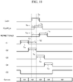
- FIGs. 5A and 5B are timing diagrams showing timings at which the pixel 321 is driven in the intermediate distance mode according to the first embodiment. Items such as "Light" and the like in Figs. 5A and 5B are similar to those shown in Figs. 12C , and thus a description thereof will be omitted.
- the intermediate distance mode does not have the electric charge accumulating unit CS in which electric charge corresponding to only external light is accumulated. In other words, a distance cannot be calculated after an external light component included in the amount of electric charge accumulated in each electric charge accumulating unit CS is extracted, and the external light component is eliminated. For this reason, in an environment in which there is a relatively low influence of an external light component on a result of calculation of a distance, for example, in an environment in which the amount of external light is small, measurement can be performed alone in the intermediate distance mode.
- the distance needs to be calculated after external light is received in the intermediate distance external light mode to be described below or using an arbitrary method, and the amount of electric charge corresponding to external light corresponding to one frame is additionally acquired.
- a light pulse PO is emitted for an emission time To, and flare light delayed by the delay time Tb and reflected light RL delayed with the delay time Td are received by the distance image sensor 32.
- the intermediate distance mode is used in a situation in which an object B that is a subject and an object A that becomes a factor for an occurrence of flare light are assumed to be at a short distance from the distance-image capturing apparatus 1 relative to that in the long-distance mode.
- the intermediate distance mode is used in a situation in which it is premised that a difference between the delay time Tb and the delay time Td is smaller than a difference assumed in the long-distance mode, and a period in which flare light and reflected light RL are simultaneously received is present.
- the timing at which the light pulse PO is emitted and the timing at which electric charge is accumulated in the electric charge accumulating units CS are adjusted such that an amount of electric charge originated from the flare light can be extracted.
- the vertical scanning circuit 323 electric charge corresponding to the flare light is distributed to the electric charge accumulating units CS 1 and CS2 to be accumulated in the electric charge accumulating units CS1 and CS2.
- electric charge corresponding to the reflected light RL is distributed to the electric charge accumulating units CS2 and CS3 to be accumulated in the electric charge accumulating units CS2 and CS3.
- the vertical scanning circuit 323 has electric charge corresponding to the amount of light incident to the light receiving unit 3 in the "flare light reception period" distributed to the electric charge accumulating units CS 1 and CS2 to be accumulated in the electric charge accumulating units CS1 and CS2.
- the vertical scanning circuit 323 has electric charge corresponding to an amount of light incident to the light receiving unit 3 in the "reflected light reception period" distributed to the electric charge accumulating units CS2 and CS3 to be accumulated in the electric charge accumulating units CS2 and CS3.
- the "flare light reception period" and the “reflected light reception period” at least partially overlap each other.
- the “flare light reception period” is a period until the light pulse emission time To (the emission period) elapses from a time acquired by delaying a time at which emission of the light pulse PO starts by the delay time Tb.
- the “flare light reception period” is a period acquired by delaying the emission time To of the light pulse PO by the delay time Tb.
- the delay time Tb is one example of a "pulse light delay time”.
- the "reflected light reception period” is a period until the light pulse emission time To (the emission period) from a time acquired by delaying a time at which emission of the light pulse PO starts by the delay time Td.
- the "reflected light reception period” is a period acquired by delaying the emission time To of the light pulse PO by the delay time Td.
- the delay time Td is one example of a "reflected light delay time”.
- the vertical scanning circuit 323, first, causes the reading gate transistor G1 to be the on state and accumulates electric charge in the electric charge accumulating unit CS1.
- the light source unit 2 starts emission of the light pulse PO at a time point at which a period TY elapses from a time point at which the reading gate transistor G1 changes to the on state. Flare light arrives at the distance-image capturing apparatus 1 at a time point at which a delay time Tb elapses from the time point at which emission of the light pulse PO starts (at an emission start time), and the flare light starts to be received.
- the vertical scanning circuit 323 causes the reading gate transistor G1 to be the on state until a period TZ elapses from the time point at which emission of the light pulse PO starts and accumulates electric charge in the electric charge accumulating unit CS1.
- a value acquired by summing the period TY and the period TZ is a period corresponding to the accumulation period Ta.
- the vertical scanning circuit 323 performs adjustment such that the period TZ is equal to or longer than the delay time Tb (TZ ⁇ Tb).
- a flare light reception start time at which reception of flare light starts can be included in the accumulation period Ta of the electric charge accumulating unit CS1, and electric charge corresponding to the flare light can be accumulated in the electric charge accumulating unit CS 1.
- the vertical scanning circuit 323 sequentially causes the reading gate transistors G2 and G3 to be the on state during the accumulation period Ta at a timing at which accumulation of electric charge in the electric charge accumulating unit CS 1 ends and accumulates electric charge in the electric charge accumulating units CS2 and CS3.
- electric charge corresponding to the flare light and the external light is distributed to the electric charge accumulating units CS 1 and CS2 to be accumulated in the electric charge accumulating units CS1 and CS2.
- electric charge corresponding to the reflected light RL and the external light is distributed to the electric charge accumulating units CS2 and CS3 to be accumulated in the electric charge accumulating units CS2 and CS3.
- the distance calculating unit 42 extracts a flare light component according to the flare light in the amount of electric charge accumulated in the electric charge accumulating unit CS2 on the basis of an amount of electric charge corresponding to the flare light accumulated in the electric charge accumulating unit CS1.
- the distance calculating unit 42 calculates a flare light component Q2f of the amount of electric charge accumulated in the electric charge accumulating unit CS2 using the following Equation (2).
- Q 2 f K ⁇ Q 1
- Q2f represents an amount of electric charge corresponding to the flare light component in the amount of electric charge accumulated in the electric charge accumulating unit CS2
- Q1 represents an amount of electric charge accumulated in the electric charge accumulating unit CS 1
- K represents a constant.
- the constant K is a constant that is uniquely determined in accordance with a time period relation between a timing at which the accumulation period Ta of the electric charge accumulating unit CS 1 ends and a timing at which reception of flare light starts.
- Fig. 5B illustrates an example of a case in which both the accumulation period Ta and the emission time To are composed of 13 clocks (13 ck).
- Fig. 5B illustrates an example in which emission of a light pulse PO starts after 10 clocks (10 ck) from a time point at which the reading gate transistor G1 comes into the on state in the intermediate distance mode.
- Q2f is an amount of electric charge of a flare light component included in the amount of electric charge accumulated in the electric charge accumulating unit CS2.
- Q1f is an amount of electric charge of a flare light component included in the amount of electric charge accumulated in the electric charge accumulating unit CS 1.
- the amount of electric charge Q1f may be regarded as the amount of electric charge accumulated in the electric charge accumulating unit CS1, in other words, the amount of electric charge Q1 represented in Equation (2).
- "11/2" represented in Equation (3) corresponds to the constant K represented in Equation (2).
- the constant K is determined on the basis of a time relation between a timing at which the accumulation period Ta of the electric charge accumulating unit CS 1 ends and a timing at which reception of flare light starts.
- the timing at which reception of flare light starts is determined in accordance with the distance to the object A (a short distance object) that becomes a factor for an occurrence of flare light present at a short distance.
- the constant K is a constant that is determined in accordance with the distance to a short distance object.
- the distance-image capturing apparatus 1 measures the distance to the short distance object, for example, in the normal mode 2. In this case, before or after measurement using the intermediate distance mode, the distance-image capturing apparatus 1 measures the distance to a short distance object in the normal mode 2. In addition, in this case, the distance-image capturing apparatus 1 stores a table in which the distance to a short distance object and a constant K are associated with each other in advance.
- the distance calculating unit 42 acquires a constant K corresponding to the measured distance to the short distance object.
- the distance calculating unit 42 applies the acquired constant K and the amounts of electric charge of the electric charge accumulating units CS1 and CS2 acquired in the intermediate distance mode to Equation (2). In this way, the distance calculating unit 42 can extract a flare light component included in the amount of electric charge accumulated in the electric charge accumulating unit CS2.
- the distance calculating unit 42 calculates an amount of electric charge corresponding to the reflected light RL accumulated in the electric charge accumulating unit CS2.
- the distance calculating unit 42 can calculate a delay time Td by applying the calculated amount of electric charge to the amount of electric charge Q2 represented in Equation (1) and calculate the distance to the object B using the calculated delay time Td.
- the amount of electric charge corresponding to external light is 0 (zero).
- the influence of the flare light component is eliminated in the distance to the object B that has been acquired in this way, and thus degradation of accuracy of a distance originated from the flare light can be inhibited.
- calculation of a distance needs to be performed with an amount of electric charge corresponding to the external light excluded, and thus it is necessary to receive external light in the intermediate distance external light mode to be described below or using an arbitrary method and additionally acquire an amount of electric charge corresponding to external light corresponding to one frame.
- Fig. 6 is a timing diagram showing timings at which pixels 321 are driven in the intermediate distance external light mode according to the first embodiment. Items such as "Light" and the like in Fig. 6 are similar to those shown in Fig. 12C , and thus a description thereof will be omitted. In addition, emission of a light pulse PO, timing relations of reception of flare light and reception of reflected light RL in Fig. 6 are similar to those shown in Fig. 5A , and thus a description thereof will be omitted.
- a timing at which the electric charge accumulating unit CS1 is caused to be the on state is advanced by an accumulation period Ta, which is different from the intermediate distance mode.
- a timing at which a light pulse PO is emitted and timings at which the electric charge accumulating units CS2 and CS3 are caused to be the on state are the same timings of the intermediate distance mode.
- an amount of electric charge corresponding to external light is accumulated in the electric charge accumulating unit CS1 in the intermediate distance external light mode.
- the timing at which a light pulse PO is emitted and the timings at which the electric charge accumulating units CS2 and CS3 are caused to be the on state are the same timings of the intermediate distance mode.
- electric charge corresponding to the flare light and the reflected light RL is accumulated in the electric charge accumulating unit CS2
- electric charge corresponding to the reflected light RL is accumulated in the electric charge accumulating unit CS3.
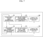
- Fig. 7 is a diagram showing a process of calculating a distance using measurement results of the intermediate distance mode and the intermediate distance external light mode that is performed by the distance-image capturing apparatus 1 according to the first embodiment.
- the distance-image capturing apparatus 1 alternately repeats measurement of one frame using the intermediate distance mode (a process F1) and measurement of one frame using the intermediate distance external light mode (a process F2).
- the distance-image capturing apparatus 1 stores at least the amount of electric charge Qlgf in the process result according to the process F1 in a frame memory and temporarily maintains a measurement result using the intermediate distance mode (the process F4).
- the process result according to the process F1 the amount of electric charge Qlgf corresponding to the flare light and the external light according to a distribution ratio corresponding to one frame, the amount of electric charge Q2grf corresponding to the flare light, the reflected light RL, and the external light according to a distribution ratio corresponding to one frame, and the amount of electric charge Q3gr corresponding to the reflected light RL and the external light according to a distribution ratio corresponding to one frame are included.
- the distance-image capturing apparatus 1 stores at least the amount of electric charge Q1g in the process result according to the process F2 in the frame memory and temporarily maintains the measurement result using the intermediate distance external light mode (the process F3).
- the process result according to the process F2 the amount of electric charge Q1g corresponding to the external light corresponding to one frame, the amount of electric charge Q2grf corresponding to the flare light, the reflected light RL, and the external light according to a distribution ratio corresponding to one frame, and the amount of electric charge Q3gr corresponding to the reflected light RL and the external light according to a distribution ratio corresponding to one frame are included.
- the distance-image capturing apparatus 1 combines the two measurement results of the intermediate distance mode and the intermediate distance external light mode according to the process result according to the process F3 and the process result according to the process F1 (the process F5).
- combination is performed using the amount of electric charge Q1g and the amount of electric charge Q1gf, the amount of electric charge Q2grf, and the amount of electric charge Q3gr of the intermediate distance mode as a process result according to the process F1.
- combination is performed using the amounts of electric charge Q1g, Q2grf, and Q3gr and the amount of electric charge Qlgf of the intermediate distance mode.
- combination is performed using the amount of electric charge Q1gf, the amount of electric charge Q2grf, and the amount of electric charge Q3gr of the intermediate distance mode.
- the distance-image capturing apparatus 1 combines two measurement results of the intermediate distance mode and the intermediate distance external light mode using the process result according to the process F4 and the process result according to the process F2 (process F6).
- a result of combination according to the process F6 a result similar to the result of the combination according to the process F5 is included.
- the distance-image capturing apparatus 1 calculates a delay time Td until the light pulse PO is reflected on the object B and is incident to the distance-image capturing apparatus 1.
- Td To ⁇ Q 3 r / Q 2 r + Q 3 r
- Q3r represents a reflected light component in the amount of electric charge Q3 accumulated in the electric charge accumulating unit CS3
- Q2r represents a reflected light component in the amount of electric charge Q2 accumulated in the electric charge accumulating unit CS2.
- the amounts of electric charge Q2g and the amount of electric charge Q3g are the same as the amount of electric charge accumulated in the electric charge accumulating unit CS1 in the intermediate distance external light mode.
- the amount of electric charge Q2f is a constant K times the flare light component in the amount of electric charge accumulated in the electric charge accumulating unit CS 1 extracted in the intermediate distance mode.
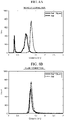
- Figs. 8A and 8B are diagrams showing the modified example of the method for calculating a constant K.
- a measurement result (distance) for each pixel is represented using a histogram.
- the horizontal axis represents a distance (Distance [m])
- the vertical axis represents the number (Count) of pixels.
- an object B is assumed to be a wall, and the distance to the wall is measured.
- Figs. 8A and the like results of measurements of the distance to the object B (denoted as Wall) in both a case in which a short distance object A (denoted as Object) is present in a measurement area (Wall + Object) and a case in which no short distance object is present (Wall) are shown.
- Fig. 8A illustrates a measurement result before elimination of flare light (no correction)
- Fig. 8B illustrates a measurement result after elimination of flare light (flare correction).
- a peak of a histogram appears near a distance of 1.2 m.
- the distance to the object B is about 1.2 m.
- a peak representing a distance (0.3 m to 0.4 m) to the short distance object A and a peak near a distance 1.0 m appear.
- the peak near the distance 1.0 m represents that the distance to the object B is measure as being shorter than an actual distance due to flare light originated from the short distance object A mixed into reflected light of the object B.
- Fig. 8B illustrates a result of calculation of a distance after a search for such a constant K that the peak near 1.0 m shown in Fig. 8A is shifted to near 1.2 m is performed and a flare light component is eliminated using the retrieved constant K.
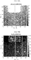
- FIGS. 9A to 9F are diagrams showing effects of measurement using the intermediate distance mode.
- Figs. 9A and 9B images (differential images) in which differences of distances for pixels are set as pixel values are shown using a distance image acquired by capturing only an object B and a distance image acquired by capturing the object B and a short distance object A.
- Fig. 9A is a differential image before elimination of a flare light component (no correction)
- Fig. 9B is a differential image after elimination of a flare light component (flare correction).
- Figs. 9A is a differential image before elimination of a flare light component (no correction)
- Fig. 9B is a differential image after elimination of a flare light component (flare correction).
- the horizontal axis represents pixels (Pixel(H)) in the horizontal direction
- the vertical axis represents pixels (Pixel(V)) in the vertical direction
- indices of difference values are shown as gray scales to the right side of the differential image and indicate that the difference becomes larger as the gray becomes brighter.
- the entire object B (wall) becomes a bright gray and illustrates that there is a difference in the distance.
- an area in the vicinity of the short distance object A (left and right sides and a lower side of the short distance object A) becomes a brighter gray, and a difference in the distance in this area is calculated to be large.
- the entire object B (wall) becomes a dark gray, and a difference in the distance is close to zero as a whole.
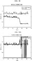
- Figs. 9C and 9D relations between pixels of vertical cross-sections (D1) of Figs. 9A and 9B and distances are shown.
- Fig. 9C illustrates a result acquired using a distance image before elimination of a flare light component (no correction)
- Fig. 9D illustrates a result acquired using a distance image after elimination of the flare light component (flare correction).
- the horizontal axis represents a pixel (Pixel)
- the vertical axis represents a distance (Distance [m])).
- a difference of 30 cm to 40 cm occurs between a case in which the short distance object A is absent (a dotted line) and a case in which the short distance object A is present (a solid line).
- a case in which flare correction is performed in a case in which flare correction is performed, a case in which the short distance object A is absent (the dotted line) and a case in which the short distance object is present (the solid line) almost overlap each other in an area in which the short distance object A is not present, and the difference decreases.
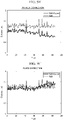
- Figs. 9E and 9F relations between pixels of vertical cross-sections (D2) of Figs. 9A and 9B and distances are shown.
- Fig. 9E illustrates a result acquired using a distance image before elimination of a flare light component (no correction)
- Fig. 9F illustrates a result acquired using a distance image after elimination of the flare light component (flare correction).
- the horizontal axis represents a pixel (Pixel)
- the vertical axis represents a distance (Distance [m])).
- a difference of 30 cm to 40 cm occurs between a case in which the short distance object A is absent (a dotted line) and a case in which the short distance object A is present (a solid line), and particularly, the difference becomes larger in accordance with approach to the position of the short distance object A (near 60 Pixel).
- a case in which flare correction is performed a case in which the short distance object A is absent (a dotted line) and a case in which the short distance object is present (a solid line) almost overlap each other, and the difference does not increase also in an area close to the short distance object A.
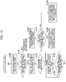
- Step S100 The distance-image capturing apparatus 1, first, performs measurement in the normal mode 1.
- the distance-image capturing apparatus 1 stores measurement results (a distance DB to an object B that is a subject, the amount of electric charge accumulated in the electric charge accumulating unit CS, and the like).
- Step S101 The distance-image capturing apparatus 1 determines whether a flare light component is present in the amount of electric charge Q2 accumulated in the electric charge accumulating unit CS2 from the measurement result using the normal mode 1.
- the distance-image capturing apparatus 1 determines that a flare light component is present in the amount of electric charge Q2. In a case in which it is determined that a flare light component is present in the amount of electric charge Q2, the distance-image capturing apparatus 1 performs the process of Step S102. On the other hand, in a case in which it is determined that a flare light component is absent in the amount of electric charge Q2, the distance-image capturing apparatus 1 returns to Step S100 and continues measurement using the normal mode 1.
- the amount of electric charge Q2 for example, an average value of the amounts of electric charge Q2 in all the pixels
- Step S102 The distance-image capturing apparatus 1 performs measurement using the normal mode 2.
- the normal mode 2 the number of times of distribution is smaller than in the normal mode 1, and the amount of exposure is suppressed, and thus the distance to a long distance subject is not measured (cannot be measured), and only the distance to the short distance object A is measured.
- the distance-image capturing apparatus 1 stores measurement results (a distance DA to the short distance object A and the like).
- Step S103 The distance-image capturing apparatus 1 determines whether re-measurement for eliminating the flare light component is performed in the long-distance mode or in the intermediate distance mode. In a case in which a difference (an absolute value) between the distance DA and the distance DB is equal to or larger than a predetermined threshold, the distance-image capturing apparatus 1 performs re-measurement in the long-distance mode. On the other hand, in a case in which a difference (an absolute value) between the distance DA and the distance DB is smaller than the predetermined threshold, the distance-image capturing apparatus 1 performs re-measurement in the intermediate distance mode.
- the distance-image capturing apparatus 1 performs a process shown in Step S104. In a case in which the re-measurement is performed in the intermediate distance mode, the distance-image capturing apparatus 1 performs a process shown in Step S106.
- Step S104 The distance-image capturing apparatus 1 performs measurement in the long-distance mode.
- the measurement in the long-distance mode for example, is performed for the same number of times of distribution as the number of times of distribution of the normal mode 1.
- Step S105 After repeating the long-distance mode for a predetermined number of frames (for example, 30 frames), the distance-image capturing apparatus 1 determines whether or not the short distance object A is continuously present. This is a process of returning to the normal mode 1 from the long-distance mode in a case in which a relation between the short distance object A and the subject changes as in a case in which the short distance object A is a mobile body or the like. The distance-image capturing apparatus 1 determines whether or not a flare light component is present in the amount of electric charge Q2 accumulated in the electric charge accumulating unit CS2 from the measurement results of the normal mode 1.
- a predetermined number of frames for example, 30 frames
- Step S101 For the determination of whether or not a flare light component is present, a method similar to that of the process shown in Step S101 may be used. In a case in which it is determined that a flare light component is present in the amount of electric charge Q2, the distance-image capturing apparatus 1 returns to the process of Step S104 and continues measurement using the long-distance mode. On the other hand, in a case in which it is determined that a flare light component is absent in the amount of electric charge Q2, the distance-image capturing apparatus 1 returns to the Step S100 and returns to the measurement using the normal mode 1.
- Step S 106 The distance-image capturing apparatus 1 performs measurement in the intermediate distance mode.
- the measurement in the intermediate distance mode for example, is performed for the same number of times of distribution as the number of times of distribution of the normal mode 1.
- the distance-image capturing apparatus 1 stores the amounts of electric charge accumulated in the electric charge accumulating units CS1 to CS3 and performs the process represented in Step S107.
- Step S107 The distance-image capturing apparatus 1 determines whether or not a flare light component is present in the amount of electric charge Q2 accumulated in the electric charge accumulating unit CS2 from the measurement results of the intermediate distance mode. This is a process corresponding to a case in which a flare light component disappears when re-measurement is performed in the intermediate distance mode such as a case in which the short distance object A is a mobile body and temporarily traverses the measurement area or the like even in a case in which it is determined that a flare light component is present in Step S101.
- a method for determining whether or not a flare light component is present in the amount of electric charge Q2 is similar to Step S101.
- the distance-image capturing apparatus 1 performs a process of Step S107.
- the distance-image capturing apparatus 1 performs a process of Step S108.
- Step S108 The distance-image capturing apparatus 1 eliminates the flare light component included in the amount of electric charge Q2 using the measurement results of the intermediate distance mode (the amounts of electric charge accumulated in the electric charge accumulating units CS1 to CS3) and calculates the distance to the object B. Although description is omitted in this flowchart, the distance-image capturing apparatus 1 calculates the distance to the object B using an external light component measured in the intermediate distance external light mode for the measurement results of the intermediate distance mode. The distance-image capturing apparatus 1 returns to the process of Step S106 and continues measurement using the intermediate distance mode.
- Step S 109 The distance-image capturing apparatus 1 calculates the distance to the object B without eliminating a flare light component of the amount of electric charge Q2 of flare light using measurement results of the intermediate distance mode (the amounts of electric charge accumulated in the electric charge accumulating units CS1 to CS3).
- the method for calculating a distance in this case is similar to a conventional calculation method.
- the distance-image capturing apparatus 1 returns to Step S100 and returns to the measurement using the normal mode 1.
- measurement of once in each measurement mode may be a measurement result corresponding to one frame, or measurement results corresponding to a plurality of frames may be averaged (for example, a moving average).
- the distance-image capturing apparatus 1 includes the light source unit 2, the light receiving unit 3, and the distance image processing unit 4.
- the light source unit 2 emits a light pulse PO into a measurement space E.
- the light receiving unit 3 includes pixels each including a photoelectric conversion device PD that generates electric charge corresponding to incident light and a plurality of electric charge accumulating units CS accumulating the electric charge and the vertical scanning circuit 323 (a pixel driving circuit) that distributes and accumulates electric charge at a predetermined accumulation timing synchronized with the emission of the light pulse PO into each of the electric charge accumulating units CS.
- the distance image processing unit 4 measures the distance to a subject S present in a measurement space E on the basis of amounts of electric charge accumulated in each of the electric charge accumulating units CS.
- the distance image processing unit 4 includes a timing control unit 41.
- the timing control unit 41 controls an accumulation timing in accordance with a measurement mode set in advance in accordance with the range of distances that are measurement targets.
- the distance-image capturing apparatus 1 according to the first embodiment can select a measurement mode in accordance with the range of distances that are measurement targets. For this reason, in a case in which there is an influence of flare light at the time of measuring an object present at a long distance, the influence of the flare light can be reduced by changing the accumulation timing.
- the influence of a flare phenomenon can be inhibited without changing the optical configuration inside the apparatus and without using a database.
- the timing control unit 41 adjusts the accumulation timing such that flare light is not received, and electric charge corresponding to the amount of the flare light is not accumulated in a case in which the measurement mode is the long-distance mode.
- a flare light component can be excluded, and effects similar to the effects described above are acquired.
- the timing control unit 41 adjusts the accumulation timing such that electric charge corresponding to flare light is distributed and accumulated into the electric charge accumulating units CS1 and CS2.
- the flare light component can be eliminated, and effects similar to the effects described above are acquired.
- the timing control unit 41 eliminates an external light component using an amount of electric charge corresponding to the external light that is separately measured. In accordance with this, elimination of the flare light component and elimination of the external light component can be performed, and effects similar to the effects described above are acquired.
- the timing control unit 41 adjusts the accumulation timing such that electric charge corresponding to external light in the intermediate distance external light mode is accumulated in the electric charge accumulating unit CS.
- the timing control unit 41 adjusts the accumulation timing such that electric charge corresponding to external light in the intermediate distance external light mode is accumulated in the electric charge accumulating unit CS.
- the distance calculating unit 42 sets a value acquired by multiplying the amount of electric charge accumulated in the electric charge accumulating unit CS 1 by the constant K as a flare light component included in the amount of electric charge accumulated in the electric charge accumulating unit CS2.
- the flare light component can be eliminated, and effects similar to the effects described above are acquired.
- measurement is performed while dynamically changing the measurement mode in accordance with a result of determination of presence/absence of flare light.
- re-measurement can be performed by performing switching between measurement modes, and effects similar to the effects described above are acquired.
- a pixel includes four electric charge accumulating units CS1 to CS4, which is different from the embodiment described above.
- Fig. 11 is a timing diagram showing timings at which pixels 321 are driven in the second embodiment. Items such as "Light" and the like in Fig. 11 are similar to those shown in Fig. 12C , and thus a description thereof will be omitted. In addition, emission of a light pulse PO, timing relations of reception of flare light and reception of reflected light RL in Fig. 11 are similar to those shown in Fig. 5A , and thus a description thereof will be omitted.
- a distance calculating unit 42 determines a constant K on the basis of the amount of electric charge accumulated in the electric charge accumulating unit CS2 and the distance to a short distance object A.
- the distance calculating unit 42 extracts a flare light component in the amount of electric charge accumulated in the electric charge accumulating unit CS3 using the constant K. By eliminating the extracted flare light component from the electric charge accumulating unit CS3, the distance calculating unit 42 calculates an amount of electric charge corresponding to reflected light RL accumulated in the electric charge accumulating unit CS3.
- the distance calculating unit 42 calculates the distance to an object using the amount of electric charge corresponding to the reflected light RL accumulated in the electric charge accumulating unit CS3 and the amounts of electric charge accumulated in the electric charge accumulating units CS1 and CS4.
- the pixel 321 includes four electric charge accumulating units CS.
- measurement using the intermediate distance mode and measurement using the intermediate distance external light mode can be simultaneously performed, and a distance can be calculated with high accuracy without performing complicated processes such as so-called frame composition and the like.
- All or a part of the distance-image capturing apparatus 1 according to the embodiment described above may be configured to be realized by a computer.
- the function may be realized.
- the "computer system” described here is a system that includes an OS and hardware such as peripherals.
- the "computer-readable recording medium” represents a portable medium such as a flexible disk, a magneto-optical disc, a ROM, or a CD-ROM or a storage device such as a hard disk built into a computer system.
- the "computer-readable recording medium” may include a medium dynamically storing the program for a short time such as a communication line of a case in which the program is transmitted through a network such as the Internet or a communication circuit line such as a telephone line and a medium storing the program for a predetermined time such as an internal volatile memory of the computer system that becomes a server or a client in such a case.
- the program described above may be a program used for realizing a part of the function described above or a program that can realize the function described above in combination with a program that is already recorded in the computer system and may be realized using a programmable logic device such as an FPGA.
- an effect according to a flare phenomenon can be inhibited without changing the optical configuration inside the apparatus and without using a database.
Landscapes
- Engineering & Computer Science (AREA)
- Physics & Mathematics (AREA)
- Electromagnetism (AREA)
- Computer Networks & Wireless Communication (AREA)
- General Physics & Mathematics (AREA)
- Radar, Positioning & Navigation (AREA)
- Remote Sensing (AREA)
- Multimedia (AREA)
- Signal Processing (AREA)
- Optical Radar Systems And Details Thereof (AREA)
- Measurement Of Optical Distance (AREA)
- Transforming Light Signals Into Electric Signals (AREA)
Applications Claiming Priority (2)
| Application Number | Priority Date | Filing Date | Title |
|---|---|---|---|
| JP2019142536A JP7463671B2 (ja) | 2019-08-01 | 2019-08-01 | 距離画像撮像装置、及び距離画像撮像方法 |
| PCT/JP2020/029199 WO2021020496A1 (ja) | 2019-08-01 | 2020-07-30 | 距離画像撮像装置、及び距離画像撮像方法 |
Publications (2)
| Publication Number | Publication Date |
|---|---|
| EP4009073A1 true EP4009073A1 (de) | 2022-06-08 |
| EP4009073A4 EP4009073A4 (de) | 2023-07-12 |
Family
ID=74230355
Family Applications (1)
| Application Number | Title | Priority Date | Filing Date |
|---|---|---|---|
| EP20847013.8A Pending EP4009073A4 (de) | 2019-08-01 | 2020-07-30 | Vorrichtung zur entfernungsbildaufnahme und verfahren zur entfernungsbildaufnahme |
Country Status (6)
| Country | Link |
|---|---|
| US (1) | US11982750B2 (de) |
| EP (1) | EP4009073A4 (de) |
| JP (1) | JP7463671B2 (de) |
| CN (1) | CN114175618B (de) |
| TW (1) | TWI780462B (de) |
| WO (1) | WO2021020496A1 (de) |
Families Citing this family (17)
| Publication number | Priority date | Publication date | Assignee | Title |
|---|---|---|---|---|
| EP4303533A4 (de) * | 2021-03-05 | 2024-08-14 | Toppan Inc. | Entfernungsbildaufnahmevorrichtung und entfernungsbildaufnahmeverfahren |
| JP7721926B2 (ja) * | 2021-03-05 | 2025-08-13 | Toppanホールディングス株式会社 | 距離画像撮像装置及び距離画像撮像方法 |
| JP7635618B2 (ja) * | 2021-04-12 | 2025-02-26 | Toppanホールディングス株式会社 | 距離画像撮像装置、及び距離画像撮像方法 |
| JP7753670B2 (ja) * | 2021-05-17 | 2025-10-15 | Toppanホールディングス株式会社 | 距離画像撮像装置及び距離画像撮像方法 |
| JP7652897B2 (ja) * | 2021-05-31 | 2025-03-27 | 日立Astemo株式会社 | 画像処理装置、および、画像処理方法 |
| JP7707659B2 (ja) * | 2021-05-31 | 2025-07-15 | Toppanホールディングス株式会社 | 距離画像撮像装置、及び距離画像撮像方法 |
| JP2022189184A (ja) * | 2021-06-10 | 2022-12-22 | ソニーセミコンダクタソリューションズ株式会社 | 測距センサ、測距装置及び測距方法 |
| DE102021123254B4 (de) * | 2021-09-08 | 2025-03-06 | Infineon Technologies Ag | Vorrichtung und Verfahren zum Erfassen einer Szene |
| JPWO2023120012A1 (de) | 2021-12-24 | 2023-06-29 | ||
| CN118575098A (zh) | 2022-01-21 | 2024-08-30 | 株式会社小糸制作所 | 测量装置 |
| US20250123374A1 (en) | 2022-02-01 | 2025-04-17 | Koito Manufacturing Co., Ltd. | Measurement device |
| CN118891894A (zh) | 2022-03-11 | 2024-11-01 | 株式会社小糸制作所 | 光电转换电路以及光电转换装置 |
| JP2023172742A (ja) * | 2022-05-24 | 2023-12-06 | Toppanホールディングス株式会社 | 距離画像撮像装置、及び距離画像撮像方法 |
| JP7848620B2 (ja) * | 2022-07-15 | 2026-04-21 | Toppanホールディングス株式会社 | 距離画像撮像装置、及び距離画像撮像方法 |
| WO2024014547A1 (ja) * | 2022-07-15 | 2024-01-18 | Toppanホールディングス株式会社 | 距離画像撮像装置、及び距離画像撮像方法 |
| JP2024060330A (ja) * | 2022-10-19 | 2024-05-02 | キヤノン株式会社 | 測距装置及び測距装置の駆動方法 |
| WO2025094648A1 (ja) * | 2023-10-30 | 2025-05-08 | ソニーセミコンダクタソリューションズ株式会社 | 測距システム、測距装置、測距方法 |
Family Cites Families (29)
| Publication number | Priority date | Publication date | Assignee | Title |
|---|---|---|---|---|
| US5705807A (en) * | 1994-10-24 | 1998-01-06 | Nissan Motor Co., Ltd. | Photo detecting apparatus for detecting reflected light from an object and excluding an external light componet from the reflected light |
| JP3820087B2 (ja) * | 1999-08-11 | 2006-09-13 | ペンタックス株式会社 | 3次元画像検出装置 |
| EP1152261A1 (de) * | 2000-04-28 | 2001-11-07 | CSEM Centre Suisse d'Electronique et de Microtechnique SA | Vorrichtung und Verfahren zur ortsauflösende Photodetektion und Demodulation von modulierten elektromagnetischen Wellen |
| WO2008152647A2 (en) * | 2007-06-15 | 2008-12-18 | Ben Gurion University Of The Negev Research And Development Authority | Three-dimensional imaging method and apparatus |
| JP4981780B2 (ja) * | 2008-10-20 | 2012-07-25 | 本田技研工業株式会社 | 測距システム及び測距方法 |
| WO2010098454A1 (ja) * | 2009-02-27 | 2010-09-02 | パナソニック電工株式会社 | 距離測定装置 |
| JP5343055B2 (ja) * | 2010-09-13 | 2013-11-13 | 本田技研工業株式会社 | 撮像装置および撮像方法 |
| JP6298236B2 (ja) * | 2013-02-22 | 2018-03-20 | スタンレー電気株式会社 | 距離画像生成装置および距離画像生成方法 |
| WO2015025497A1 (ja) * | 2013-08-23 | 2015-02-26 | パナソニックIpマネジメント株式会社 | 測距システム及び信号発生装置 |
| US9900485B2 (en) * | 2014-01-08 | 2018-02-20 | Mitsubishi Electric Corporation | Image generation device |
| CN105899966B (zh) * | 2014-01-14 | 2019-05-07 | 松下知识产权经营株式会社 | 距离图像生成装置以及距离图像生成方法 |
| US10578741B2 (en) * | 2014-11-11 | 2020-03-03 | Panasonic Intellectual Property Management Co., Ltd. | Distance detection device and distance detection method |
| JP2016189557A (ja) * | 2015-03-30 | 2016-11-04 | ソニー株式会社 | 撮像素子およびその駆動方法、並びに電子機器 |
| US10250833B2 (en) * | 2015-04-20 | 2019-04-02 | Samsung Electronics Co., Ltd. | Timestamp calibration of the 3D camera with epipolar line laser point scanning |
| CN106257915B (zh) * | 2015-06-17 | 2021-02-26 | 松下知识产权经营株式会社 | 摄像装置 |
| JP6799538B2 (ja) * | 2015-08-04 | 2020-12-16 | ヌヴォトンテクノロジージャパン株式会社 | 固体撮像装置の駆動方法 |
| JP2017133853A (ja) * | 2016-01-25 | 2017-08-03 | 株式会社リコー | 測距装置 |
| KR102796731B1 (ko) * | 2016-02-19 | 2025-04-16 | 삼성전자주식회사 | 전자 장치 및 그의 동작 방법 |
| WO2017170568A1 (ja) * | 2016-03-30 | 2017-10-05 | 国立大学法人静岡大学 | 画素回路及び撮像素子 |
| EP3467765B1 (de) * | 2016-05-23 | 2024-10-23 | Sony Group Corporation | Elektronische vorrichtung, steuerungsverfahren für elektronische vorrichtung und programm |
| JP6834211B2 (ja) * | 2016-07-15 | 2021-02-24 | 株式会社リコー | 測距装置、移動体、ロボット、3次元計測装置及び測距方法 |
| KR101832364B1 (ko) * | 2017-02-22 | 2018-04-04 | 경희대학교 산학협력단 | 재귀 반사 필름을 이용한 거리 측정 장치 및 방법 |
| JP2018185179A (ja) * | 2017-04-25 | 2018-11-22 | 株式会社リコー | 測距装置、監視装置、3次元計測装置、移動体、ロボット及び測距方法 |
| JP7194443B2 (ja) * | 2017-10-20 | 2022-12-22 | 国立大学法人静岡大学 | 距離画像測定装置及び距離画像測定方法 |
| WO2019123825A1 (ja) * | 2017-12-22 | 2019-06-27 | ソニーセミコンダクタソリューションズ株式会社 | 信号生成装置 |
| EP3572832B1 (de) * | 2017-12-22 | 2025-02-12 | Sony Semiconductor Solutions Corporation | Impulsgenerator und signalerzeugungsvorrichtung |
| JP2019142536A (ja) | 2018-02-20 | 2019-08-29 | レンゴー株式会社 | トレイ |
| WO2020178920A1 (ja) * | 2019-03-01 | 2020-09-10 | 株式会社ブルックマンテクノロジ | 距離画像撮像装置および距離画像撮像装置による距離画像撮像方法 |
| US11598860B2 (en) * | 2019-03-20 | 2023-03-07 | Brookman Technology, Inc. | Distance image capturing device, distance image capturing system, and distance image capturing method |
-
2019
- 2019-08-01 JP JP2019142536A patent/JP7463671B2/ja active Active
-
2020
- 2020-07-30 CN CN202080054290.1A patent/CN114175618B/zh active Active
- 2020-07-30 EP EP20847013.8A patent/EP4009073A4/de active Pending
- 2020-07-30 WO PCT/JP2020/029199 patent/WO2021020496A1/ja not_active Ceased
- 2020-07-31 TW TW109125942A patent/TWI780462B/zh active
-
2022
- 2022-01-27 US US17/586,447 patent/US11982750B2/en active Active
Also Published As
| Publication number | Publication date |
|---|---|
| US20220146684A1 (en) | 2022-05-12 |
| TWI780462B (zh) | 2022-10-11 |
| JP7463671B2 (ja) | 2024-04-09 |
| TW202112122A (zh) | 2021-03-16 |
| CN114175618A (zh) | 2022-03-11 |
| CN114175618B (zh) | 2024-06-14 |
| US11982750B2 (en) | 2024-05-14 |
| EP4009073A4 (de) | 2023-07-12 |
| JP2021025833A (ja) | 2021-02-22 |
| WO2021020496A1 (ja) | 2021-02-04 |
Similar Documents
| Publication | Publication Date | Title |
|---|---|---|
| US11982750B2 (en) | Distance-image capturing apparatus and distance-image capturing method | |
| US10764518B2 (en) | Pixel structure | |
| US10739135B2 (en) | Distance measuring apparatus | |
| US20230358863A1 (en) | Range imaging device and range imaging method | |
| US11626446B2 (en) | Pixel circuit and method of operating the same in an always-on mode | |
| US11336854B2 (en) | Distance image capturing apparatus and distance image capturing method using distance image capturing apparatus | |
| EP3987305B1 (de) | Direkte flugzeittiefensensorarchitektur und verfahren zum betrieb eines solchen sensors | |
| US20220043129A1 (en) | Time flight depth camera and multi-frequency modulation and demodulation distance measuring method | |
| US20250085404A1 (en) | Range imaging apparatus and range imaging method | |
| US20250035790A1 (en) | Range imaging apparatus and range imaging method | |
| CN116710803A (zh) | 距离图像摄像装置以及距离图像摄像方法 | |
| US20260029535A1 (en) | Distance image capturing device and distance image capturing method | |
| US20250370132A1 (en) | Distance image capturing device and distance image capturing method | |
| CN114829970A (zh) | 飞行时间成像电路、飞行时间成像系统和飞行时间成像方法 | |
| US20250155576A1 (en) | Range imaging device and range imaging method | |
| US20250116514A1 (en) | Distance image capturing device and distance image capturing method | |
| US20240022833A1 (en) | Range imaging device and range imaging method | |
| JP2024078837A (ja) | 距離画像撮像装置、及び距離画像撮像方法 | |
| US20250189638A1 (en) | Time-of-flight system and method | |
| JP2025117801A (ja) | 距離画像撮像装置、及び距離画像撮像方法 | |
| JP2023180900A (ja) | 距離画像撮像装置、及び距離画像撮像方法 |
Legal Events
| Date | Code | Title | Description |
|---|---|---|---|
| STAA | Information on the status of an ep patent application or granted ep patent |
Free format text: STATUS: THE INTERNATIONAL PUBLICATION HAS BEEN MADE |
|
| PUAI | Public reference made under article 153(3) epc to a published international application that has entered the european phase |
Free format text: ORIGINAL CODE: 0009012 |
|
| STAA | Information on the status of an ep patent application or granted ep patent |
Free format text: STATUS: REQUEST FOR EXAMINATION WAS MADE |
|
| 17P | Request for examination filed |
Effective date: 20220131 |
|
| AK | Designated contracting states |
Kind code of ref document: A1 Designated state(s): AL AT BE BG CH CY CZ DE DK EE ES FI FR GB GR HR HU IE IS IT LI LT LU LV MC MK MT NL NO PL PT RO RS SE SI SK SM TR |
|
| DAV | Request for validation of the european patent (deleted) | ||
| DAX | Request for extension of the european patent (deleted) | ||
| A4 | Supplementary search report drawn up and despatched |
Effective date: 20230612 |
|
| RIC1 | Information provided on ipc code assigned before grant |
Ipc: H04N 25/771 20230101ALI20230605BHEP Ipc: H04N 25/531 20230101ALI20230605BHEP Ipc: G01S 17/894 20200101ALI20230605BHEP Ipc: G01S 7/4865 20200101ALI20230605BHEP Ipc: G01S 7/4863 20200101ALI20230605BHEP Ipc: G01S 17/89 20200101ALI20230605BHEP Ipc: G01C 3/06 20060101ALI20230605BHEP Ipc: G01S 7/497 20060101AFI20230605BHEP |
|
| RAP1 | Party data changed (applicant data changed or rights of an application transferred) |
Owner name: TOPPAN HOLDINGS INC. |
|
| STAA | Information on the status of an ep patent application or granted ep patent |
Free format text: STATUS: EXAMINATION IS IN PROGRESS |
|
| 17Q | First examination report despatched |
Effective date: 20240321 |
|
| GRAP | Despatch of communication of intention to grant a patent |
Free format text: ORIGINAL CODE: EPIDOSNIGR1 |
|
| STAA | Information on the status of an ep patent application or granted ep patent |
Free format text: STATUS: GRANT OF PATENT IS INTENDED |
|
| INTG | Intention to grant announced |
Effective date: 20260318 |