EP4009090B1 - Module de caméra et son procédé de mise au point automatique - Google Patents
Module de caméra et son procédé de mise au point automatique Download PDFInfo
- Publication number
- EP4009090B1 EP4009090B1 EP21211982.0A EP21211982A EP4009090B1 EP 4009090 B1 EP4009090 B1 EP 4009090B1 EP 21211982 A EP21211982 A EP 21211982A EP 4009090 B1 EP4009090 B1 EP 4009090B1
- Authority
- EP
- European Patent Office
- Prior art keywords
- mover
- posture
- camera module
- actuator
- lens
- Prior art date
- Legal status (The legal status is an assumption and is not a legal conclusion. Google has not performed a legal analysis and makes no representation as to the accuracy of the status listed.)
- Active
Links
Images


Classifications
-
- G—PHYSICS
- G02—OPTICS
- G02B—OPTICAL ELEMENTS, SYSTEMS OR APPARATUS
- G02B7/00—Mountings, adjusting means, or light-tight connections, for optical elements
- G02B7/02—Mountings, adjusting means, or light-tight connections, for optical elements for lenses
- G02B7/04—Mountings, adjusting means, or light-tight connections, for optical elements for lenses with mechanism for focusing or varying magnification
- G02B7/08—Mountings, adjusting means, or light-tight connections, for optical elements for lenses with mechanism for focusing or varying magnification adapted to co-operate with a remote control mechanism
-
- G—PHYSICS
- G03—PHOTOGRAPHY; CINEMATOGRAPHY; ANALOGOUS TECHNIQUES USING WAVES OTHER THAN OPTICAL WAVES; ELECTROGRAPHY; HOLOGRAPHY
- G03B—APPARATUS OR ARRANGEMENTS FOR TAKING PHOTOGRAPHS OR FOR PROJECTING OR VIEWING THEM; APPARATUS OR ARRANGEMENTS EMPLOYING ANALOGOUS TECHNIQUES USING WAVES OTHER THAN OPTICAL WAVES; ACCESSORIES THEREFOR
- G03B13/00—Viewfinders; Focusing aids for cameras; Means for focusing for cameras; Autofocus systems for cameras
- G03B13/32—Means for focusing
- G03B13/34—Power focusing
- G03B13/36—Autofocus systems
-
- G—PHYSICS
- G03—PHOTOGRAPHY; CINEMATOGRAPHY; ANALOGOUS TECHNIQUES USING WAVES OTHER THAN OPTICAL WAVES; ELECTROGRAPHY; HOLOGRAPHY
- G03B—APPARATUS OR ARRANGEMENTS FOR TAKING PHOTOGRAPHS OR FOR PROJECTING OR VIEWING THEM; APPARATUS OR ARRANGEMENTS EMPLOYING ANALOGOUS TECHNIQUES USING WAVES OTHER THAN OPTICAL WAVES; ACCESSORIES THEREFOR
- G03B3/00—Focusing arrangements of general interest for cameras, projectors or printers
- G03B3/10—Power-operated focusing
-
- H—ELECTRICITY
- H04—ELECTRIC COMMUNICATION TECHNIQUE
- H04N—PICTORIAL COMMUNICATION, e.g. TELEVISION
- H04N23/00—Cameras or camera modules comprising electronic image sensors; Control thereof
- H04N23/50—Constructional details
- H04N23/54—Mounting of pick-up tubes, electronic image sensors, deviation or focusing coils
-
- H—ELECTRICITY
- H04—ELECTRIC COMMUNICATION TECHNIQUE
- H04N—PICTORIAL COMMUNICATION, e.g. TELEVISION
- H04N23/00—Cameras or camera modules comprising electronic image sensors; Control thereof
- H04N23/57—Mechanical or electrical details of cameras or camera modules specially adapted for being embedded in other devices
-
- H—ELECTRICITY
- H04—ELECTRIC COMMUNICATION TECHNIQUE
- H04N—PICTORIAL COMMUNICATION, e.g. TELEVISION
- H04N23/00—Cameras or camera modules comprising electronic image sensors; Control thereof
- H04N23/60—Control of cameras or camera modules
- H04N23/67—Focus control based on electronic image sensor signals
Definitions
- the teachings in accordance with exemplary and non-limiting embodiments of this disclosure relate generally to a camera module and a method for auto focusing the camera module.
- a conventional digital camera module mounted on the mobile phones has suffered from disadvantages in that a gap between an image sensor converting an outside light to a digital image or a digital video and a lens cannot be adjusted.
- a lens driving device such as a VCM (Voice Coil Motor) configured to adjust a gap between an image sensor and a lens has been recently developed to enable a camera module to obtain a further improved digital image and a digital video.
- VCM Vehicle Coil Motor
- a VCM mounted on a camera module is configured such that a mover mounted with a lens therein moves upward from a base to adjust a gap between the lens and an image sensor arranged at a rear surface of the base.
- the conventional VCM is configured such that an elastic member presses the mover to contact the base in a case no driving signal is applied. That is, the conventional VCM is configured such that, under a state where the elastic member presses the mover, an electromagnetic force for driving the mover must be greater than elasticity of the elastic member and self-weight of the mover in order to allow the mover to be distanced from the base.
- the mover of the conventional VCM has a displacement of approximately 30 ⁇ m to 50 ⁇ m depending on posture of the VCM.
- the mover in the conventional VCM suffers from disadvantages in that it has a displacement depending on the posture of the VCM, includes a non-moving section where the mover is not driven even if a driving signal is applied, and the mover is driven by an auto focus algorithm not reflected therewith to thereby take too much time for auto focusing.
- a camera module according to the present invention is claimed in claim 1.
- a method for auto focusing a camera module according to the present invention is claimed in claim 5.
- the camera module comprises:
- a bit allocated to drive the first search section may be -LSB (Least Significant Bit) ⁇ 0, and a bit allocated to drive the second search section may be 0 - LSB.
- LSB east Significant Bit
- a bit allocated to drive the first search section may be 0 ⁇ MSB (Most Significant Bit), and a bit allocated to drive the second search section may be -LSB ⁇ 0.
- the camera module comprises: a posture detection unit outputting a posture data by detecting a posture of the mover, and a controller receiving the posture data outputted by the posture detection unit and outputting a control signal to the actuator driving unit.
- the posture of the mover is one of an 'UP' posture of the lens, a 'SIDE' posture of the lens and a 'DOWN' posture of the lens.
- the actuator further includes an elastic member fixed at one side to the mover, and fixed at the other side opposite to the one side to the stator, to elastically support the mover.
- one half may be allocated to drive the first search section and the other half may be allocated to drive the second search section.
- the first search section and the second search section may be symmetrical.
- the first search section and the second search section may be asymmetrical.
- an LSB Least Significant Bit allocated between the first and second search sections may be within a 300 ⁇ 500 LSB scope.
- an LSB Least Significant Bit allocated between the first and second search sections may be within a 500 ⁇ 1000 LSB scope.
- a method for auto focusing a camera module as disclosed comprises:
- the focusing is performed to a forward direction using a separate direction bit.
- a method for auto focusing a camera module as disclosed comprises:
- the method may further include searching the best focusing point by moving the mover to the macro, in a case the focusing value increases to the macro direction in the step of determining whether an increase of focusing value is the infinity direction or the macro direction using the first search.
- the method further includes reducing a mechanical impact sound by lengthening a time of moving the mover to the infinity direction or the macro direction in an initial step over that of other steps.
- the method includes reducing a mechanical impact sound by dividing a step size of initially moving the mover to the infinity direction or the macro direction to several stages.
- an algorithm driving an actuator can be simplified by designating a current value for each address and by allocating a search section in which a mover can be driven to a forward direction and a reverse direction in a -1023-1023 bit scope using a forward direction bit and a reverse direction bit.
- resolution can be increased by driving the mover to both directions.
- a consumed current can be reduced and a camera module is optimally driven by detecting a posture of a VCM or a lens and by controlling the VCM using the posture data.
- a defocusing problem can be solved by applying a current to a reverse direction even if there is a change in a spring due to a mover being drivable to both directions.
- an algorithm driving an actuator can be simplified by designating a current value for each address and by allocating a search section in which a mover can be driven to a forward direction and a reverse direction using a forward direction bit and a reverse direction bit.
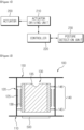
- FIG. 1 is a schematic block diagram illustrating a configuration of a camera module according to an exemplary embodiment of the present disclosure.
- the camera module is configured such that a mover including at least one lens is driven to both directions (forward direction or reverse direction), and an LSB (Least Significant Bit) allocated to drive to both directions may be -1023 ⁇ 1023.
- the camera module includes an actuator (200) moving a mover including at least one lens receiving an optical image of an object, and an actuator driving unit (210) controlling the actuator (200) to drive the mover to both directions.
- the actuator driving unit (210) controls the actuator (200) to drive the mover to a forward direction or to a reverse direction.
- a bit allocated to drive the first search section may be -LSB-0
- a bit allocated to drive the second search section may be 0-MSB (Most Significant Bit)
- a bit allocated to drive the first search section may be 0-MSB
- a bit allocated to drive the second search section may be -LSB-0.
- an LSB allocated to drive to the first and second search sections may be -1023-1023.
- the LSB to drive the first search section may be -1023-0, or an LSB to drive the second search section may be 0 ⁇ 1023.
- the first search section and the second search section may be symmetrical or asymmetrical.
- the camera module according to an exemplary embodiment of the present disclosure can increase a resolving power of the camera module, because a direction bit can be added to a forward direction and a reverse direction to drive a mover to the forward direction and the reverse direction at -1023-1023 LSB, and a one-fold resolution can be possessed with a same number of bits over a case where no direction bit is available.
- the camera module according to the present disclosure further includes a posture detection unit (230) outputting a posture data by detecting a posture of the mover, and a controller (220) receiving the posture data outputted by the posture detection unit (230) and outputting a control signal to the actuator driving unit (210).
- a posture detection unit (230) outputting a posture data by detecting a posture of the mover
- a controller (220) receiving the posture data outputted by the posture detection unit (230) and outputting a control signal to the actuator driving unit (210).
- the posture detection unit (230) detects a posture of the mover and outputs a posture data
- the controller (220) receives the posture data from the posture detection unit (230) and outputs a control signal corresponding to the posture of the mover to the actuator driving unit (210), and the actuator driving unit (210) appropriately drives the actuator (200) in response to the posture of the mover.
- the posture of the mover is one of an 'UP' posture of the lens, a 'SIDE' posture of the lens and a 'DOWN' posture of the lens, as will be described later.
- the posture detection unit (230) may sense more than the three kinds of postures, description will be made on sensing of the three postures of UP, SIDE and DOWN postures for convenience sake in the exemplary embodiment of the present disclosure.
- the actuator (200) may be one of a VCM (Voice Coil Motor) actuator, an actuator driven by piezoelectric power, and a MEMS (Micro Electro Mechanical System) actuator driven by electrostatic capacity method.
- VCM Vehicle Coil Motor
- MEMS Micro Electro Mechanical System
- the VCM performs an auto focusing of the camera module by driving the mover in response to an electromagnetic force.
- the posture detection unit (230) may include a gyro sensor configured to detect a gravitational direction.
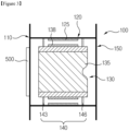
- FIG.2 is a schematic cross-sectional view illustrating a lens of a camera module being positioned at an upper surface direction according to an exemplary embodiment of the present disclosure
- FIG.3 is a schematic cross-sectional view illustrating a lens of a camera module being positioned at a lateral surface direction according to an exemplary embodiment of the present disclosure
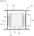
- FIG.4 is a schematic cross-sectional view illustrating a lens of a camera module being positioned at a bottom surface direction according to an exemplary embodiment of the present disclosure.
- FIG.2 illustrates an UP POSTURE where a lens of a camera module is positioned at an up direction
- the UP POSTURE may be defined that an optical axis of a lens (135) of a mover (130) of a VCM is formed perpendicular to a ground, and a base (110) is arranged opposite to the ground.
- FIG.3 illustrates a SIDE POSTURE where a lens of a camera module is positioned at a lateral direction
- the SIDE POSTURE may be defined that an optical axis of the lens (135) of the mover (130) of the VCM is formed parallel with the ground, and the base (110) is arranged perpendicular to the ground.
- FIG.4 illustrates a DOWN POSTURE where a lens of a camera module is positioned at a down direction, and the DOWN POSTURE may be defined that an optical axis of the lens (135) of the mover (130) of the VCM is formed perpendicular to the ground, and a cover (150) is arranged opposite to the ground.
- a VCM (100) is used for the actuator in FIGS. 2 , 3 and 4 , where the mover (130), a stator (120), the base (110), an elastic member (140) and the cover (150) may be parts of the VCM (100).
- the VCM (100) performs the auto focusing function by driving the mover (130) to a forward direction or to a reverse direction.
- the mover (130) mounted on the VCM (100) is driven to a forward direction ascending to the cover (150), or to a reverse direction descending to the base (110), and the auto focusing operation is performed between the lens (135) and an image sensor (500) in the midst of the ascending or descending operation process. That is, the mover (130) is spaced apart from the cover (150) and the base (110).
- the base (110) takes a shape of a plate centrally formed with an opening to pass light, and the base (110) serves to function as a bottom stopper of the mover (130).
- the image sensor (500) may be arranged at a rear surface or a rear side of the base (110). The image sensor (500) converts the light focused through the lens of the mover (130) to a digital image or a video.
- the method includes reducing a mechanical impact sound by lengthening a time of moving the mover to the infinity direction or the macro direction in an initial step over that of other steps. Still furthermore, the method includes reducing a mechanical impact sound by dividing a step size of initially moving the mover to the infinity direction or the macro direction to several stages.
- the camera module includes an actuator (1200) moving a mover including at least one lens receiving an optical image of an object, and an actuator driving unit (1210) controlling the actuator (1200) to drive the mover to a forward direction or to a reverse direction, where the actuator driving unit (1210) controls the actuator (1200) to drive the mover to the forward direction or to the reverse direction.
- a driving scope of the mover by the actuator driving unit (1210) includes a first search section and a second search section, in a case a search section driving the mover to the forward direction is defined as the first search section, and a search section driving the mover to the reverse direction is defined as the second search section.
- an LSB allocated to drive the first search section and the second search section may be 0 - 1023.
- an LSB allocated to drive the first search section may be 0 - 513, and an LSB allocated to drive the second search section is 513 - 1023.
- the first search section and the second search section are symmetrical or asymmetrical.
- an LSB allocated between the first and second search sections may be within a 300 ⁇ 500 LSB scope, and an LSB allocated between the first and second search sections may be within a 500 ⁇ 1000 LSB scope.
- the camera module according to present disclosure is advantageous in that an algorithm driving an actuator can be simplified even if there is no information whether to move an actuator to a forward direction or a reverse direction, by adding a direction bit to the forward direction and the reverse direction, and by designating a current value for each address and by allocating a search section in which a mover can be driven to the forward direction and the reverse direction in a 0 ⁇ 1023 LSB.
- a camera module includes a posture detection unit (1230) outputting a posture data by detecting a posture of the mover, and a controller (1220) receiving the posture data outputted by the posture detection unit (1230) and outputting a control signal to the actuator driving unit (1210).
- the posture detection unit (1230) outputs the posture data by detecting a posture of the mover
- the controller (1220) receives the posture data outputted by the posture detection unit (1230) and outputs a control signal corresponding to the posture of the mover to the actuator driving unit (1210)
- the actuator driving unit (1210) appropriately drives the actuator (1200) in response to the posture of the mover.
- the posture of the mover is one of an 'UP' posture of the lens, a 'SIDE' posture of the lens and a 'DOWN' posture of the lens.
- the posture detection unit (1230) may sense more than the three kinds of postures, description will be made on sensing by the posture detection unit (1230) of the three postures of UP, SIDE and DOWN postures for convenience sake in the exemplary embodiment of the present disclosure.
- the actuator (1200) may be one of a VCM (Voice Coil Motor) actuator, an actuator driven by piezoelectric power, and a MEMS (Micro Electro Mechanical System) actuator driven by electrostatic capacity method.
- VCM Voice Coil Motor
- MEMS Micro Electro Mechanical System
- the VCM performs an auto focusing of the camera module by driving the mover in response to an electromagnetic force.
- the posture detection unit (1230) may include a gyro sensor configured to detect a gravitational direction.
- FIG.8 is a graph illustrating a current-distance characteristic of a camera module according to the present disclosure.
- the camera module according to the present disclosure is configured such that an LSB bit is 0 ⁇ 513 that is allocated to drive the first search section where the mover is driven to a reverse direction (-) including a lens, and an LSB bit is 513 ⁇ 1023 that is allocated to drive the second search section where the mover is driven to a forward direction (+), where the number of bits allocated to a reverse direction may increase or decrease depending on a current value or a reverse stroke.
- a current value may be -50mA, and in a case the LSB is 513, a current value may be 0mA, and in a case the LSB is 1023, a current value may be +50mA.
- FIG.9 is a flowchart for illustrating a method for auto focusing a camera module according to the present disclosure.
- the method for auto focusing a camera module includes performing a first search by moving a mover including a lens (S200). Successively, a determination is made as to whether an increase of focusing value is an infinity direction or a macro direction using the first search (S210). The mover is then moved to the infinity to search a best focusing point, if it is determined that the focusing value increases to the infinity direction (S220), where, in a case the focusing value increases to the macro direction in the step (S210) of determining whether an increase of focusing value is the infinity direction or the macro direction using the first search, the best focusing point is searched by moving the mover to the macro (S230).
- the focusing is performed to the searched best focusing point, where the method includes reducing a mechanical impact sound by lengthening a time of moving the mover to the infinity direction or the macro direction in an initial step over that of other steps, and further includes reducing a mechanical impact sound by dividing a step size of initially moving the mover to the infinity direction or the macro direction to several stages.
- the exemplary embodiments of the present disclosure has an industrial applicability in that an algorithm driving an actuator can be simplified, resolution can be increased, a consumed current can be reduced and a defocusing problem can be solved.
Landscapes
- Physics & Mathematics (AREA)
- General Physics & Mathematics (AREA)
- Engineering & Computer Science (AREA)
- Multimedia (AREA)
- Signal Processing (AREA)
- Optics & Photonics (AREA)
- Lens Barrels (AREA)
- Studio Devices (AREA)
Claims (5)
- Un module de caméra comprenant :une base (110) ;un stator (120) disposé sur la base (110) ;un couvercle (150) fixé à la base (110) et enveloppant le stator (120) ;un dispositif de mouvement (130) disposé dans le couvercle (150) et comprenant une lentille (135) ;un élément élastique (140) reliant le dispositif de mouvement (130) et le stator (120) ;un actionneur (200, 1200) comprenant une bobine disposée sur le dispositif de mouvement (130) et un aimant disposé dans le couvercle (150) et faisant face à la bobine ; etune unité d'entraînement de l'actionneur (210, 1210) configurée pour commander l'actionneur (200, 1200) afin de déplacer le dispositif de mouvement (130) vers l'avant ou vers l'arrière,dans lequel le dispositif de mouvement (130) est séparé du couvercle (150) par un premier écart et de la base (110) par un second écart lorsqu'aucun courant n'est appliqué à l'actionneur (200, 1200),caractérisé en ce que :un bit de direction est attribué dans l'unité d'entraînement de l'actionneur (210, 1210), dans lequel le bit de direction comprend une information de mouvement vers l'avant selon laquelle le dispositif de mouvement (130) se déplace vers le couvercle (150) pour réduire le premier écart et une information de mouvement inverse selon laquelle le dispositif de mouvement (130) se déplace vers la base (110) pour réduire le second écart,dans lequel l'unité d'entraînement de l'actionneur (210, 1210) est configurée pour déplacer le dispositif de mouvement (130) d'une position initiale à une position infinie ou à une position macro, puis pour rechercher un meilleur point de mise au point en déplaçant le dispositif de mouvement (130) de la position infinie à la position macro ou de la position macro à la position infinie, et ensuite pour effectuer une mise au point à l'aide du meilleur point de mise au point,caractérisé en ce que :l'unité d'entraînement de l'actionneur (210, 1210) est configurée pour déplacer le dispositif de mouvement (130) le long d'une pluralité d'étapes de déplacement, la pluralité d'étapes de déplacement comprenant une première étape et une deuxième étape suivant la première étape, et l'unité d'entraînement de l'actionneur (210, 1210) est configurée pour allonger le temps de déplacement du dispositif de mouvement (130) dans la première étape par rapport à celle de la deuxième étape afin de réduire un bruit d'impact mécanique,dans lequel le module de caméra comprend :une unité de détection de posture (230, 1230) émettant des données de posture en détectant la posture du dispositif de posture (130), etun dispositif de commande (220, 1220) configuré pour recevoir les données de posture émises par l'unité de détection de posture (230, 1230) et pour émettre un signal de commande à l'unité d'entraînement de l'actionneur (210, 1210) pour entraîner l'actionneur (200) en réponse à la posture du dispositif de mouvement, etdans lequel la posture du dispositif de mouvement (130) est l'une des postures suivantes : "HAUT" de la lentille (135), "CÔTÉ" de la lentille (135) et "BAS" de la lentille (135).
- Module de caméra selon la revendication 1, dans lequel l'élément élastique (140) comprend un premier élément élastique (143) couplé à une surface inférieure du dispositif de mouvement (130), et un deuxième élément élastique (146) couplé à une surface supérieure du dispositif de mouvement (130).
- Module de caméra selon l'une quelconque des revendications 1 à 2, dans lequel la base (110) sert de butée inférieure pour arrêter le dispositif de mouvement (130), et dans lequel le couvercle (150) sert de butée supérieure pour arrêter le dispositif de mouvement (130).
- Module de caméra selon l'une quelconque des revendications 1 à 3, comprenant un capteur d'image (500) disposé sur une surface arrière de la base (110).
- Méthode de mise au point automatique du module de caméra selon la revendication 1, dans laquelle, lorsque le bit de direction est alloué comme bit de direction inverse, le dispositif de mouvement (130) est déplacé vers la position infinie, et lorsque le bit de direction est alloué comme bit de direction avant, le dispositif de mouvement (130) est déplacé vers la position macro.
Priority Applications (1)
| Application Number | Priority Date | Filing Date | Title |
|---|---|---|---|
| EP25159605.2A EP4550819A3 (fr) | 2012-05-17 | 2013-04-26 | Module de caméra et procédé de mise au point automatique de celui-ci |
Applications Claiming Priority (5)
| Application Number | Priority Date | Filing Date | Title |
|---|---|---|---|
| KR1020120052338A KR102077850B1 (ko) | 2012-05-17 | 2012-05-17 | 카메라 모듈 및 그의 오토 포커싱 방법 |
| KR1020120052339A KR102077849B1 (ko) | 2012-05-17 | 2012-05-17 | 카메라 모듈 및 그의 오토 포커싱 방법 |
| EP13791147.5A EP2850492B1 (fr) | 2012-05-17 | 2013-04-26 | Module de caméra et procédé de mise au point de celui-ci |
| PCT/KR2013/003600 WO2013172566A1 (fr) | 2012-05-17 | 2013-04-26 | Module de caméra et procédé de mise au point de celui-ci |
| EP19212583.9A EP3650931B1 (fr) | 2012-05-17 | 2013-04-26 | Module de caméra et son procédé de mise au point automatique |
Related Parent Applications (3)
| Application Number | Title | Priority Date | Filing Date |
|---|---|---|---|
| EP13791147.5A Division EP2850492B1 (fr) | 2012-05-17 | 2013-04-26 | Module de caméra et procédé de mise au point de celui-ci |
| EP19212583.9A Division EP3650931B1 (fr) | 2012-05-17 | 2013-04-26 | Module de caméra et son procédé de mise au point automatique |
| EP19212583.9A Division-Into EP3650931B1 (fr) | 2012-05-17 | 2013-04-26 | Module de caméra et son procédé de mise au point automatique |
Related Child Applications (1)
| Application Number | Title | Priority Date | Filing Date |
|---|---|---|---|
| EP25159605.2A Division EP4550819A3 (fr) | 2012-05-17 | 2013-04-26 | Module de caméra et procédé de mise au point automatique de celui-ci |
Publications (2)
| Publication Number | Publication Date |
|---|---|
| EP4009090A1 EP4009090A1 (fr) | 2022-06-08 |
| EP4009090B1 true EP4009090B1 (fr) | 2025-02-26 |
Family
ID=49583936
Family Applications (4)
| Application Number | Title | Priority Date | Filing Date |
|---|---|---|---|
| EP21211982.0A Active EP4009090B1 (fr) | 2012-05-17 | 2013-04-26 | Module de caméra et son procédé de mise au point automatique |
| EP19212583.9A Active EP3650931B1 (fr) | 2012-05-17 | 2013-04-26 | Module de caméra et son procédé de mise au point automatique |
| EP13791147.5A Active EP2850492B1 (fr) | 2012-05-17 | 2013-04-26 | Module de caméra et procédé de mise au point de celui-ci |
| EP25159605.2A Pending EP4550819A3 (fr) | 2012-05-17 | 2013-04-26 | Module de caméra et procédé de mise au point automatique de celui-ci |
Family Applications After (3)
| Application Number | Title | Priority Date | Filing Date |
|---|---|---|---|
| EP19212583.9A Active EP3650931B1 (fr) | 2012-05-17 | 2013-04-26 | Module de caméra et son procédé de mise au point automatique |
| EP13791147.5A Active EP2850492B1 (fr) | 2012-05-17 | 2013-04-26 | Module de caméra et procédé de mise au point de celui-ci |
| EP25159605.2A Pending EP4550819A3 (fr) | 2012-05-17 | 2013-04-26 | Module de caméra et procédé de mise au point automatique de celui-ci |
Country Status (4)
| Country | Link |
|---|---|
| US (2) | US9568805B2 (fr) |
| EP (4) | EP4009090B1 (fr) |
| CN (2) | CN108303834B (fr) |
| WO (1) | WO2013172566A1 (fr) |
Families Citing this family (7)
| Publication number | Priority date | Publication date | Assignee | Title |
|---|---|---|---|---|
| CN104678679A (zh) * | 2015-03-30 | 2015-06-03 | 信利光电股份有限公司 | 一种拍摄设备及其自动对焦模组 |
| CN104777980B (zh) * | 2015-04-22 | 2017-08-11 | 广东欧珀移动通信有限公司 | 一种高分辨率终端的省电方法和装置 |
| KR102508248B1 (ko) * | 2015-08-20 | 2023-03-08 | 삼성전자주식회사 | 중력 및 온도 센서를 이용한 카메라의 자동 초점 조절 방법, 카메라 제어 장치, 및 카메라 시스템 |
| CN108781256B (zh) * | 2016-03-09 | 2020-08-11 | Lg 电子株式会社 | 控制相机模块的自动聚焦的装置和方法 |
| CN108429884A (zh) * | 2018-06-05 | 2018-08-21 | 昆山丘钛微电子科技有限公司 | 一种对焦方法、装置、设备及介质 |
| CN110830726B (zh) * | 2019-12-24 | 2022-01-28 | 西安易朴通讯技术有限公司 | 一种自动对焦方法、装置、设备和存储介质 |
| CN111175952A (zh) * | 2019-12-31 | 2020-05-19 | Oppo广东移动通信有限公司 | 变焦镜头、相机模组和电子装置 |
Citations (1)
| Publication number | Priority date | Publication date | Assignee | Title |
|---|---|---|---|---|
| US20110159919A1 (en) * | 2009-12-21 | 2011-06-30 | Lg Innotek Co., Ltd. | Mobile Phone |
Family Cites Families (37)
| Publication number | Priority date | Publication date | Assignee | Title |
|---|---|---|---|---|
| JPS5886893A (ja) * | 1981-11-16 | 1983-05-24 | Minolta Camera Co Ltd | モ−タ駆動制御装置 |
| US6643451B1 (en) * | 1998-03-25 | 2003-11-04 | Sanyo Electric Co., Ltd | Image data alteration preventing apparatus and alteration preventing method |
| EP1730587B1 (fr) * | 2004-03-15 | 2010-09-01 | Cambridge Mechatronics Limited | Mise au point automatique de camera |
| EP1610447B1 (fr) * | 2004-06-14 | 2009-09-09 | Matsushita Electric Works, Ltd. | Unité d'entraînement |
| JP2006189506A (ja) * | 2004-12-28 | 2006-07-20 | Fuji Photo Film Co Ltd | カメラ |
| TWI265668B (en) * | 2005-12-23 | 2006-11-01 | Ind Tech Res Inst | Axial movement actuator |
| KR100806690B1 (ko) * | 2006-03-07 | 2008-02-27 | 삼성전기주식회사 | 자동초점 수행 방법 및 이를 이용한 자동초점 조정장치 |
| TW200742923A (en) * | 2006-05-11 | 2007-11-16 | Asia Optical Co Inc | Method of auto focus |
| KR20080006723A (ko) * | 2006-07-13 | 2008-01-17 | 엘지전자 주식회사 | 할바흐 배열을 이용한 음성 코일 모터 카메라 장치 |
| JP4986551B2 (ja) * | 2006-09-06 | 2012-07-25 | 三洋電機株式会社 | レンズ駆動制御装置 |
| JP4717766B2 (ja) * | 2006-09-14 | 2011-07-06 | キヤノン株式会社 | 画像表示装置、撮像装置、画像表示方法、記憶媒体、及び、プログラム |
| CN201018387Y (zh) * | 2007-01-22 | 2008-02-06 | 泓记精密股份有限公司 | 高效能音圈马达 |
| JP4952364B2 (ja) * | 2007-05-07 | 2012-06-13 | コニカミノルタオプト株式会社 | 駆動ユニットおよび可動モジュール |
| JP4957366B2 (ja) * | 2007-05-09 | 2012-06-20 | コニカミノルタアドバンストレイヤー株式会社 | カメラモジュールおよびカメラモジュールの駆動方法 |
| JP4552974B2 (ja) * | 2007-06-22 | 2010-09-29 | カシオ計算機株式会社 | カメラ装置、フォーカス制御方法及びプログラム |
| KR101396344B1 (ko) | 2007-06-25 | 2014-05-19 | 삼성전자주식회사 | 영상에 위치정보를 입력하는 시스템 및 그 동작 방법 |
| FR2922695A1 (fr) * | 2007-10-22 | 2009-04-24 | St Microelectronics Grenoble | Circuit de commande de moteur a bobine mobile |
| CN101483376B (zh) * | 2008-01-10 | 2011-05-18 | 财团法人工业技术研究院 | 音圈马达 |
| JP2009271405A (ja) * | 2008-05-09 | 2009-11-19 | Mitsumi Electric Co Ltd | カメラモジュール |
| KR100965337B1 (ko) | 2008-09-22 | 2010-06-22 | 삼성전기주식회사 | 카메라모듈용 피에조 액추에이터의 구동장치 및 구동방법 |
| WO2010050200A1 (fr) * | 2008-10-30 | 2010-05-06 | パナソニック株式会社 | Système d'appareil photo |
| KR20100062657A (ko) * | 2008-12-02 | 2010-06-10 | (주)차바이오앤디오스텍 | 촬상 장치용 렌즈 액츄에이터 |
| JP2010262223A (ja) * | 2009-05-11 | 2010-11-18 | Panasonic Corp | カメラ、携帯端末装置及びレンズの位置制御方法 |
| JP2011070178A (ja) * | 2009-08-28 | 2011-04-07 | Panasonic Corp | レンズ鏡筒および撮像装置 |
| KR101664352B1 (ko) * | 2009-09-09 | 2016-10-10 | 엘지이노텍 주식회사 | Vcm 엑추에이터를 이용한 자동 초점조절방법 |
| JP5534760B2 (ja) * | 2009-09-24 | 2014-07-02 | 日本電産サンキョー株式会社 | 振れ補正機能付きの光学ユニット |
| JP2011112520A (ja) * | 2009-11-27 | 2011-06-09 | Sony Corp | 位置検知装置、撮像装置および位置検知方法 |
| US9167143B2 (en) * | 2009-12-07 | 2015-10-20 | Nokia Technologies Oy | Apparatus, a method, and a computer program for automatic focusing |
| KR101220735B1 (ko) * | 2010-02-22 | 2013-01-09 | 엘지이노텍 주식회사 | 보이스 코일 모터 |
| KR101095108B1 (ko) * | 2010-03-23 | 2011-12-16 | 삼성전기주식회사 | 카메라 모듈 |
| US9036076B2 (en) * | 2010-06-29 | 2015-05-19 | Nikon Corporation | Interchangeable lens, camera body and camera system for transmitting drive condition information at different frequencies |
| KR101126295B1 (ko) | 2010-10-26 | 2012-03-20 | 엘지이노텍 주식회사 | 카메라 모듈 및 그의 오토 포커싱 탐색 범위 설정 방법 |
| KR101164755B1 (ko) * | 2010-11-02 | 2012-07-12 | 엘지이노텍 주식회사 | 보이스 코일 모터 및 이의 구동 방법 |
| US9184677B2 (en) * | 2010-12-06 | 2015-11-10 | Nikon Corporation | Driving device, lens barrel, and image capturing apparatus |
| KR101808858B1 (ko) * | 2011-04-07 | 2018-01-18 | 엘지이노텍 주식회사 | 보이스 코일 모터 |
| US8908083B2 (en) * | 2011-09-28 | 2014-12-09 | Apple Inc. | Dynamic autofocus operations |
| KR102001621B1 (ko) * | 2011-11-30 | 2019-07-18 | 엘지이노텍 주식회사 | 보이스 코일 모터 및 이의 구동 방법 |
-
2013
- 2013-04-26 EP EP21211982.0A patent/EP4009090B1/fr active Active
- 2013-04-26 EP EP19212583.9A patent/EP3650931B1/fr active Active
- 2013-04-26 EP EP13791147.5A patent/EP2850492B1/fr active Active
- 2013-04-26 WO PCT/KR2013/003600 patent/WO2013172566A1/fr not_active Ceased
- 2013-04-26 CN CN201810060485.1A patent/CN108303834B/zh active Active
- 2013-04-26 CN CN201380025716.0A patent/CN104321699B/zh active Active
- 2013-04-26 US US14/399,379 patent/US9568805B2/en active Active
- 2013-04-26 EP EP25159605.2A patent/EP4550819A3/fr active Pending
-
2016
- 2016-12-27 US US15/391,303 patent/US9678409B2/en active Active
Patent Citations (1)
| Publication number | Priority date | Publication date | Assignee | Title |
|---|---|---|---|---|
| US20110159919A1 (en) * | 2009-12-21 | 2011-06-30 | Lg Innotek Co., Ltd. | Mobile Phone |
Also Published As
| Publication number | Publication date |
|---|---|
| CN108303834B (zh) | 2022-02-08 |
| CN104321699B (zh) | 2018-02-23 |
| US20170108758A1 (en) | 2017-04-20 |
| CN108303834A (zh) | 2018-07-20 |
| EP4009090A1 (fr) | 2022-06-08 |
| EP3650931A1 (fr) | 2020-05-13 |
| EP2850492A4 (fr) | 2016-01-20 |
| US9568805B2 (en) | 2017-02-14 |
| EP2850492A1 (fr) | 2015-03-25 |
| WO2013172566A1 (fr) | 2013-11-21 |
| EP4550819A3 (fr) | 2025-07-09 |
| EP2850492B1 (fr) | 2019-12-25 |
| US9678409B2 (en) | 2017-06-13 |
| EP3650931B1 (fr) | 2022-01-12 |
| EP4550819A2 (fr) | 2025-05-07 |
| US20150098008A1 (en) | 2015-04-09 |
| CN104321699A (zh) | 2015-01-28 |
Similar Documents
| Publication | Publication Date | Title |
|---|---|---|
| US9678409B2 (en) | Camera module and method for auto focusing the same | |
| US9723198B2 (en) | Camera module and auto focusing method of camera module | |
| KR101743053B1 (ko) | 카메라 모듈 및 그 구동 방법 | |
| KR102628090B1 (ko) | 카메라 모듈의 오토 포커스 제어 장치 및 방법 | |
| KR101126295B1 (ko) | 카메라 모듈 및 그의 오토 포커싱 탐색 범위 설정 방법 | |
| KR102876630B1 (ko) | 이동단말의 카메라모듈의 오토 포커싱 방법 및 이를 적용한 이동단말 | |
| KR102077849B1 (ko) | 카메라 모듈 및 그의 오토 포커싱 방법 | |
| KR102077850B1 (ko) | 카메라 모듈 및 그의 오토 포커싱 방법 | |
| US20140333725A1 (en) | 3-dimensional camera module and method for auto focusing the same | |
| KR102452740B1 (ko) | 카메라 모듈 및 그의 오토 포커싱 방법 | |
| KR102318960B1 (ko) | 카메라 모듈 및 그의 오토 포커싱 방법 | |
| KR102315448B1 (ko) | 카메라 모듈 및 그의 오토 포커싱 방법 | |
| KR102164662B1 (ko) | 카메라 모듈 및 그의 오토 포커싱 방법 | |
| KR102167779B1 (ko) | 카메라 모듈 및 그의 오토 포커싱 방법 | |
| KR102103561B1 (ko) | 카메라 모듈 | |
| KR20130077217A (ko) | 카메라 모듈 및 카메라 모듈의 오토 포커싱 방법 | |
| KR102308955B1 (ko) | 카메라 모듈 | |
| US20210360162A1 (en) | Control apparatus, image pickup apparatus, control method, and memory medium | |
| JP2008176063A (ja) | カメラモジュール |
Legal Events
| Date | Code | Title | Description |
|---|---|---|---|
| PUAI | Public reference made under article 153(3) epc to a published international application that has entered the european phase |
Free format text: ORIGINAL CODE: 0009012 |
|
| STAA | Information on the status of an ep patent application or granted ep patent |
Free format text: STATUS: THE APPLICATION HAS BEEN PUBLISHED |
|
| AC | Divisional application: reference to earlier application |
Ref document number: 2850492 Country of ref document: EP Kind code of ref document: P Ref document number: 3650931 Country of ref document: EP Kind code of ref document: P |
|
| AK | Designated contracting states |
Kind code of ref document: A1 Designated state(s): AL AT BE BG CH CY CZ DE DK EE ES FI FR GB GR HR HU IE IS IT LI LT LU LV MC MK MT NL NO PL PT RO RS SE SI SK SM TR |
|
| STAA | Information on the status of an ep patent application or granted ep patent |
Free format text: STATUS: REQUEST FOR EXAMINATION WAS MADE |
|
| 17P | Request for examination filed |
Effective date: 20221205 |
|
| RBV | Designated contracting states (corrected) |
Designated state(s): AL AT BE BG CH CY CZ DE DK EE ES FI FR GB GR HR HU IE IS IT LI LT LU LV MC MK MT NL NO PL PT RO RS SE SI SK SM TR |
|
| STAA | Information on the status of an ep patent application or granted ep patent |
Free format text: STATUS: EXAMINATION IS IN PROGRESS |
|
| 17Q | First examination report despatched |
Effective date: 20230630 |
|
| GRAP | Despatch of communication of intention to grant a patent |
Free format text: ORIGINAL CODE: EPIDOSNIGR1 |
|
| STAA | Information on the status of an ep patent application or granted ep patent |
Free format text: STATUS: GRANT OF PATENT IS INTENDED |
|
| RIC1 | Information provided on ipc code assigned before grant |
Ipc: H04N 23/67 20230101ALI20240906BHEP Ipc: H04N 23/54 20230101ALI20240906BHEP Ipc: G03B 13/36 20210101ALI20240906BHEP Ipc: G03B 3/10 20210101ALI20240906BHEP Ipc: G02B 7/08 20210101AFI20240906BHEP |
|
| INTG | Intention to grant announced |
Effective date: 20240919 |
|
| GRAS | Grant fee paid |
Free format text: ORIGINAL CODE: EPIDOSNIGR3 |
|
| GRAA | (expected) grant |
Free format text: ORIGINAL CODE: 0009210 |
|
| STAA | Information on the status of an ep patent application or granted ep patent |
Free format text: STATUS: THE PATENT HAS BEEN GRANTED |
|
| AC | Divisional application: reference to earlier application |
Ref document number: 2850492 Country of ref document: EP Kind code of ref document: P Ref document number: 3650931 Country of ref document: EP Kind code of ref document: P |
|
| AK | Designated contracting states |
Kind code of ref document: B1 Designated state(s): AL AT BE BG CH CY CZ DE DK EE ES FI FR GB GR HR HU IE IS IT LI LT LU LV MC MK MT NL NO PL PT RO RS SE SI SK SM TR |
|
| REG | Reference to a national code |
Ref country code: GB Ref legal event code: FG4D |
|
| REG | Reference to a national code |
Ref country code: CH Ref legal event code: EP |
|
| REG | Reference to a national code |
Ref country code: DE Ref legal event code: R096 Ref document number: 602013086551 Country of ref document: DE |
|
| REG | Reference to a national code |
Ref country code: IE Ref legal event code: FG4D |
|
| REG | Reference to a national code |
Ref country code: NL Ref legal event code: MP Effective date: 20250226 |
|
| PG25 | Lapsed in a contracting state [announced via postgrant information from national office to epo] |
Ref country code: RS Free format text: LAPSE BECAUSE OF FAILURE TO SUBMIT A TRANSLATION OF THE DESCRIPTION OR TO PAY THE FEE WITHIN THE PRESCRIBED TIME-LIMIT Effective date: 20250526 |
|
| PG25 | Lapsed in a contracting state [announced via postgrant information from national office to epo] |
Ref country code: FI Free format text: LAPSE BECAUSE OF FAILURE TO SUBMIT A TRANSLATION OF THE DESCRIPTION OR TO PAY THE FEE WITHIN THE PRESCRIBED TIME-LIMIT Effective date: 20250226 |
|
| PG25 | Lapsed in a contracting state [announced via postgrant information from national office to epo] |
Ref country code: PL Free format text: LAPSE BECAUSE OF FAILURE TO SUBMIT A TRANSLATION OF THE DESCRIPTION OR TO PAY THE FEE WITHIN THE PRESCRIBED TIME-LIMIT Effective date: 20250226 |
|
| PGFP | Annual fee paid to national office [announced via postgrant information from national office to epo] |
Ref country code: DE Payment date: 20250422 Year of fee payment: 13 |
|
| PG25 | Lapsed in a contracting state [announced via postgrant information from national office to epo] |
Ref country code: ES Free format text: LAPSE BECAUSE OF FAILURE TO SUBMIT A TRANSLATION OF THE DESCRIPTION OR TO PAY THE FEE WITHIN THE PRESCRIBED TIME-LIMIT Effective date: 20250226 |
|
| REG | Reference to a national code |
Ref country code: LT Ref legal event code: MG9D |
|
| PG25 | Lapsed in a contracting state [announced via postgrant information from national office to epo] |
Ref country code: NO Free format text: LAPSE BECAUSE OF FAILURE TO SUBMIT A TRANSLATION OF THE DESCRIPTION OR TO PAY THE FEE WITHIN THE PRESCRIBED TIME-LIMIT Effective date: 20250526 Ref country code: IS Free format text: LAPSE BECAUSE OF FAILURE TO SUBMIT A TRANSLATION OF THE DESCRIPTION OR TO PAY THE FEE WITHIN THE PRESCRIBED TIME-LIMIT Effective date: 20250626 |
|
| PG25 | Lapsed in a contracting state [announced via postgrant information from national office to epo] |
Ref country code: NL Free format text: LAPSE BECAUSE OF FAILURE TO SUBMIT A TRANSLATION OF THE DESCRIPTION OR TO PAY THE FEE WITHIN THE PRESCRIBED TIME-LIMIT Effective date: 20250226 |
|
| PG25 | Lapsed in a contracting state [announced via postgrant information from national office to epo] |
Ref country code: HR Free format text: LAPSE BECAUSE OF FAILURE TO SUBMIT A TRANSLATION OF THE DESCRIPTION OR TO PAY THE FEE WITHIN THE PRESCRIBED TIME-LIMIT Effective date: 20250226 |
|
| PG25 | Lapsed in a contracting state [announced via postgrant information from national office to epo] |
Ref country code: PT Free format text: LAPSE BECAUSE OF FAILURE TO SUBMIT A TRANSLATION OF THE DESCRIPTION OR TO PAY THE FEE WITHIN THE PRESCRIBED TIME-LIMIT Effective date: 20250626 Ref country code: LV Free format text: LAPSE BECAUSE OF FAILURE TO SUBMIT A TRANSLATION OF THE DESCRIPTION OR TO PAY THE FEE WITHIN THE PRESCRIBED TIME-LIMIT Effective date: 20250226 |
|
| PG25 | Lapsed in a contracting state [announced via postgrant information from national office to epo] |
Ref country code: GR Free format text: LAPSE BECAUSE OF FAILURE TO SUBMIT A TRANSLATION OF THE DESCRIPTION OR TO PAY THE FEE WITHIN THE PRESCRIBED TIME-LIMIT Effective date: 20250527 Ref country code: BG Free format text: LAPSE BECAUSE OF FAILURE TO SUBMIT A TRANSLATION OF THE DESCRIPTION OR TO PAY THE FEE WITHIN THE PRESCRIBED TIME-LIMIT Effective date: 20250226 |
|
| REG | Reference to a national code |
Ref country code: AT Ref legal event code: MK05 Ref document number: 1771183 Country of ref document: AT Kind code of ref document: T Effective date: 20250226 |
|
| PG25 | Lapsed in a contracting state [announced via postgrant information from national office to epo] |
Ref country code: SE Free format text: LAPSE BECAUSE OF FAILURE TO SUBMIT A TRANSLATION OF THE DESCRIPTION OR TO PAY THE FEE WITHIN THE PRESCRIBED TIME-LIMIT Effective date: 20250226 |
|
| PG25 | Lapsed in a contracting state [announced via postgrant information from national office to epo] |
Ref country code: SM Free format text: LAPSE BECAUSE OF FAILURE TO SUBMIT A TRANSLATION OF THE DESCRIPTION OR TO PAY THE FEE WITHIN THE PRESCRIBED TIME-LIMIT Effective date: 20250226 |
|
| PG25 | Lapsed in a contracting state [announced via postgrant information from national office to epo] |
Ref country code: DK Free format text: LAPSE BECAUSE OF FAILURE TO SUBMIT A TRANSLATION OF THE DESCRIPTION OR TO PAY THE FEE WITHIN THE PRESCRIBED TIME-LIMIT Effective date: 20250226 |
|
| PG25 | Lapsed in a contracting state [announced via postgrant information from national office to epo] |
Ref country code: IT Free format text: LAPSE BECAUSE OF FAILURE TO SUBMIT A TRANSLATION OF THE DESCRIPTION OR TO PAY THE FEE WITHIN THE PRESCRIBED TIME-LIMIT Effective date: 20250226 |
|
| PG25 | Lapsed in a contracting state [announced via postgrant information from national office to epo] |
Ref country code: AT Free format text: LAPSE BECAUSE OF FAILURE TO SUBMIT A TRANSLATION OF THE DESCRIPTION OR TO PAY THE FEE WITHIN THE PRESCRIBED TIME-LIMIT Effective date: 20250226 |
|
| PG25 | Lapsed in a contracting state [announced via postgrant information from national office to epo] |
Ref country code: EE Free format text: LAPSE BECAUSE OF FAILURE TO SUBMIT A TRANSLATION OF THE DESCRIPTION OR TO PAY THE FEE WITHIN THE PRESCRIBED TIME-LIMIT Effective date: 20250226 Ref country code: CZ Free format text: LAPSE BECAUSE OF FAILURE TO SUBMIT A TRANSLATION OF THE DESCRIPTION OR TO PAY THE FEE WITHIN THE PRESCRIBED TIME-LIMIT Effective date: 20250226 |
|
| PG25 | Lapsed in a contracting state [announced via postgrant information from national office to epo] |
Ref country code: RO Free format text: LAPSE BECAUSE OF FAILURE TO SUBMIT A TRANSLATION OF THE DESCRIPTION OR TO PAY THE FEE WITHIN THE PRESCRIBED TIME-LIMIT Effective date: 20250226 |
|
| PG25 | Lapsed in a contracting state [announced via postgrant information from national office to epo] |
Ref country code: SK Free format text: LAPSE BECAUSE OF FAILURE TO SUBMIT A TRANSLATION OF THE DESCRIPTION OR TO PAY THE FEE WITHIN THE PRESCRIBED TIME-LIMIT Effective date: 20250226 |
|
| REG | Reference to a national code |
Ref country code: CH Ref legal event code: H13 Free format text: ST27 STATUS EVENT CODE: U-0-0-H10-H13 (AS PROVIDED BY THE NATIONAL OFFICE) Effective date: 20251125 |
|
| REG | Reference to a national code |
Ref country code: DE Ref legal event code: R097 Ref document number: 602013086551 Country of ref document: DE |
|
| PG25 | Lapsed in a contracting state [announced via postgrant information from national office to epo] |
Ref country code: LU Free format text: LAPSE BECAUSE OF NON-PAYMENT OF DUE FEES Effective date: 20250426 |
|
| PG25 | Lapsed in a contracting state [announced via postgrant information from national office to epo] |
Ref country code: MC Free format text: LAPSE BECAUSE OF FAILURE TO SUBMIT A TRANSLATION OF THE DESCRIPTION OR TO PAY THE FEE WITHIN THE PRESCRIBED TIME-LIMIT Effective date: 20250226 |
|
| REG | Reference to a national code |
Ref country code: BE Ref legal event code: MM Effective date: 20250430 |
|
| PLBE | No opposition filed within time limit |
Free format text: ORIGINAL CODE: 0009261 |
|
| STAA | Information on the status of an ep patent application or granted ep patent |
Free format text: STATUS: NO OPPOSITION FILED WITHIN TIME LIMIT |
|
| PG25 | Lapsed in a contracting state [announced via postgrant information from national office to epo] |
Ref country code: BE Free format text: LAPSE BECAUSE OF NON-PAYMENT OF DUE FEES Effective date: 20250430 |
|
| PG25 | Lapsed in a contracting state [announced via postgrant information from national office to epo] |
Ref country code: CH Free format text: LAPSE BECAUSE OF NON-PAYMENT OF DUE FEES Effective date: 20250430 |
|
| GBPC | Gb: european patent ceased through non-payment of renewal fee |
Effective date: 20250526 |
|
| 26N | No opposition filed |
Effective date: 20251127 |
|
| PG25 | Lapsed in a contracting state [announced via postgrant information from national office to epo] |
Ref country code: GB Free format text: LAPSE BECAUSE OF NON-PAYMENT OF DUE FEES Effective date: 20250526 |
|
| PG25 | Lapsed in a contracting state [announced via postgrant information from national office to epo] |
Ref country code: IE Free format text: LAPSE BECAUSE OF NON-PAYMENT OF DUE FEES Effective date: 20250426 |
|
| PGFP | Annual fee paid to national office [announced via postgrant information from national office to epo] |
Ref country code: FR Payment date: 20260323 Year of fee payment: 14 |