EP4009235A1 - Système de commutation ou de surveillance des appareils de commande à moyenne tension - Google Patents
Système de commutation ou de surveillance des appareils de commande à moyenne tension Download PDFInfo
- Publication number
- EP4009235A1 EP4009235A1 EP20212076.2A EP20212076A EP4009235A1 EP 4009235 A1 EP4009235 A1 EP 4009235A1 EP 20212076 A EP20212076 A EP 20212076A EP 4009235 A1 EP4009235 A1 EP 4009235A1
- Authority
- EP
- European Patent Office
- Prior art keywords
- current carrying
- carrying parts
- infrared image
- image
- processing unit
- Prior art date
- Legal status (The legal status is an assumption and is not a legal conclusion. Google has not performed a legal analysis and makes no representation as to the accuracy of the status listed.)
- Pending
Links
Images

Classifications
-
- H—ELECTRICITY
- H02—GENERATION; CONVERSION OR DISTRIBUTION OF ELECTRIC POWER
- H02B—BOARDS, SUBSTATIONS OR SWITCHING ARRANGEMENTS FOR THE SUPPLY OR DISTRIBUTION OF ELECTRIC POWER
- H02B13/00—Arrangement of switchgear in which switches are enclosed in, or structurally associated with, a casing, e.g. cubicle
- H02B13/02—Arrangement of switchgear in which switches are enclosed in, or structurally associated with, a casing, e.g. cubicle with metal casing
- H02B13/035—Gas-insulated switchgear
- H02B13/065—Means for detecting or reacting to mechanical or electrical defects
-
- G—PHYSICS
- G06—COMPUTING OR CALCULATING; COUNTING
- G06T—IMAGE DATA PROCESSING OR GENERATION, IN GENERAL
- G06T7/00—Image analysis
- G06T7/0002—Inspection of images, e.g. flaw detection
- G06T7/0004—Industrial image inspection
-
- G—PHYSICS
- G06—COMPUTING OR CALCULATING; COUNTING
- G06F—ELECTRIC DIGITAL DATA PROCESSING
- G06F18/00—Pattern recognition
- G06F18/20—Analysing
- G06F18/21—Design or setup of recognition systems or techniques; Extraction of features in feature space; Blind source separation
- G06F18/214—Generating training patterns; Bootstrap methods, e.g. bagging or boosting
- G06F18/2155—Generating training patterns; Bootstrap methods, e.g. bagging or boosting characterised by the incorporation of unlabelled data, e.g. multiple instance learning [MIL], semi-supervised techniques using expectation-maximisation [EM] or naïve labelling
-
- G—PHYSICS
- G01—MEASURING; TESTING
- G01J—MEASUREMENT OF INTENSITY, VELOCITY, SPECTRAL CONTENT, POLARISATION, PHASE OR PULSE CHARACTERISTICS OF INFRARED, VISIBLE OR ULTRAVIOLET LIGHT; COLORIMETRY; RADIATION PYROMETRY
- G01J5/00—Radiation pyrometry, e.g. infrared or optical thermometry
- G01J5/0096—Radiation pyrometry, e.g. infrared or optical thermometry for measuring wires, electrical contacts or electronic systems
-
- G—PHYSICS
- G06—COMPUTING OR CALCULATING; COUNTING
- G06F—ELECTRIC DIGITAL DATA PROCESSING
- G06F18/00—Pattern recognition
- G06F18/20—Analysing
- G06F18/22—Matching criteria, e.g. proximity measures
-
- G—PHYSICS
- G06—COMPUTING OR CALCULATING; COUNTING
- G06N—COMPUTING ARRANGEMENTS BASED ON SPECIFIC COMPUTATIONAL MODELS
- G06N3/00—Computing arrangements based on biological models
- G06N3/02—Neural networks
- G06N3/04—Architecture, e.g. interconnection topology
- G06N3/045—Combinations of networks
-
- G—PHYSICS
- G06—COMPUTING OR CALCULATING; COUNTING
- G06N—COMPUTING ARRANGEMENTS BASED ON SPECIFIC COMPUTATIONAL MODELS
- G06N3/00—Computing arrangements based on biological models
- G06N3/02—Neural networks
- G06N3/04—Architecture, e.g. interconnection topology
- G06N3/045—Combinations of networks
- G06N3/0455—Auto-encoder networks; Encoder-decoder networks
-
- G—PHYSICS
- G06—COMPUTING OR CALCULATING; COUNTING
- G06N—COMPUTING ARRANGEMENTS BASED ON SPECIFIC COMPUTATIONAL MODELS
- G06N3/00—Computing arrangements based on biological models
- G06N3/02—Neural networks
- G06N3/08—Learning methods
- G06N3/088—Non-supervised learning, e.g. competitive learning
-
- G—PHYSICS
- G06—COMPUTING OR CALCULATING; COUNTING
- G06N—COMPUTING ARRANGEMENTS BASED ON SPECIFIC COMPUTATIONAL MODELS
- G06N3/00—Computing arrangements based on biological models
- G06N3/02—Neural networks
- G06N3/08—Learning methods
- G06N3/0895—Weakly supervised learning, e.g. semi-supervised or self-supervised learning
-
- G—PHYSICS
- G06—COMPUTING OR CALCULATING; COUNTING
- G06T—IMAGE DATA PROCESSING OR GENERATION, IN GENERAL
- G06T11/00—Two-dimensional [2D] image generation
-
- G—PHYSICS
- G06—COMPUTING OR CALCULATING; COUNTING
- G06V—IMAGE OR VIDEO RECOGNITION OR UNDERSTANDING
- G06V10/00—Arrangements for image or video recognition or understanding
- G06V10/10—Image acquisition
- G06V10/12—Details of acquisition arrangements; Constructional details thereof
- G06V10/14—Optical characteristics of the device performing the acquisition or on the illumination arrangements
- G06V10/143—Sensing or illuminating at different wavelengths
-
- G—PHYSICS
- G06—COMPUTING OR CALCULATING; COUNTING
- G06V—IMAGE OR VIDEO RECOGNITION OR UNDERSTANDING
- G06V10/00—Arrangements for image or video recognition or understanding
- G06V10/70—Arrangements for image or video recognition or understanding using pattern recognition or machine learning
- G06V10/74—Image or video pattern matching; Proximity measures in feature spaces
- G06V10/761—Proximity, similarity or dissimilarity measures
-
- G—PHYSICS
- G06—COMPUTING OR CALCULATING; COUNTING
- G06V—IMAGE OR VIDEO RECOGNITION OR UNDERSTANDING
- G06V20/00—Scenes; Scene-specific elements
- G06V20/50—Context or environment of the image
- G06V20/52—Surveillance or monitoring of activities, e.g. for recognising suspicious objects
-
- H—ELECTRICITY
- H04—ELECTRIC COMMUNICATION TECHNIQUE
- H04N—PICTORIAL COMMUNICATION, e.g. TELEVISION
- H04N23/00—Cameras or camera modules comprising electronic image sensors; Control thereof
- H04N23/20—Cameras or camera modules comprising electronic image sensors; Control thereof for generating image signals from infrared radiation only
-
- G—PHYSICS
- G06—COMPUTING OR CALCULATING; COUNTING
- G06N—COMPUTING ARRANGEMENTS BASED ON SPECIFIC COMPUTATIONAL MODELS
- G06N3/00—Computing arrangements based on biological models
- G06N3/02—Neural networks
- G06N3/08—Learning methods
-
- G—PHYSICS
- G06—COMPUTING OR CALCULATING; COUNTING
- G06T—IMAGE DATA PROCESSING OR GENERATION, IN GENERAL
- G06T2207/00—Indexing scheme for image analysis or image enhancement
- G06T2207/10—Image acquisition modality
- G06T2207/10048—Infrared image
-
- G—PHYSICS
- G06—COMPUTING OR CALCULATING; COUNTING
- G06T—IMAGE DATA PROCESSING OR GENERATION, IN GENERAL
- G06T2207/00—Indexing scheme for image analysis or image enhancement
- G06T2207/20—Special algorithmic details
- G06T2207/20084—Artificial neural networks [ANN]
-
- H—ELECTRICITY
- H01—ELECTRIC ELEMENTS
- H01H—ELECTRIC SWITCHES; RELAYS; SELECTORS; EMERGENCY PROTECTIVE DEVICES
- H01H1/00—Contacts
- H01H1/0015—Means for testing or for inspecting contacts, e.g. wear indicator
- H01H2001/0021—Camera or endoscope for monitoring contacts, their position or mechanism
-
- H—ELECTRICITY
- H02—GENERATION; CONVERSION OR DISTRIBUTION OF ELECTRIC POWER
- H02B—BOARDS, SUBSTATIONS OR SWITCHING ARRANGEMENTS FOR THE SUPPLY OR DISTRIBUTION OF ELECTRIC POWER
- H02B13/00—Arrangement of switchgear in which switches are enclosed in, or structurally associated with, a casing, e.g. cubicle
- H02B13/02—Arrangement of switchgear in which switches are enclosed in, or structurally associated with, a casing, e.g. cubicle with metal casing
- H02B13/025—Safety arrangements, e.g. in case of excessive pressure or fire due to electrical defect
-
- H—ELECTRICITY
- H02—GENERATION; CONVERSION OR DISTRIBUTION OF ELECTRIC POWER
- H02B—BOARDS, SUBSTATIONS OR SWITCHING ARRANGEMENTS FOR THE SUPPLY OR DISTRIBUTION OF ELECTRIC POWER
- H02B3/00—Apparatus specially adapted for the manufacture, assembly, or maintenance of boards or switchgear
Definitions
- the present invention relates to a medium voltage switchgear or controlgear monitoring system and medium voltage switchgear or controlgear monitoring method.
- thermographic thermographic
- a medium voltage switchgear or controlgear monitoring system comprising: - an infrared camera; and - a processing unit.
- the infrared camera is configured to be mounted within a medium voltage switchgear or controlgear.
- the infrared camera is configured to acquire an infrared image.
- the infrared image comprises image data of two or three current carrying parts of the switchgear or control gear.
- the two or three current carrying parts are the same current carry part of two or three equivalent systems within the switchgear or controlgear.
- the infrared camera is configured to provide the infrared image to the processing unit.
- the processing unit is configured to determine that the two or three current carrying parts are operating correctly or that one of the two or three current carrying parts has a fault, where this determination comprises analysis of the infrared image by an autoencoder implemented by the processing unit.
- a neural network in the form of an autoencoder is utilized to determine a fault in a current carrying par of for example a switchgear.
- the autoencoder is good at reproducing images that it has been trained with, but not good at reproducing images that it has not been trained with.
- the autoencoder can reproduce such input images imagery such that a generated output image matches the input image within a threshold.
- one of the current carrying parts is faulty and is at a higher temperature than it should be the associated imagery will represent this higher temperature for this part with respect to the other parts.
- this new image representing a fault is input to the autoencoder, the output it generates cannot match the input within the threshold and an alarm can be generated that there is a fault.
- the autoencoder is configured to utilize the infrared image to generate a synthetic infrared image.
- the synthetic infrared image comprises synthetic image data of the two or three current carrying parts of the switchgear or control gear.
- the determination that the two or three current carrying parts are operating correctly or that one of the two or three current carrying parts has a fault comprises a comparison of the infrared image with the synthetic infrared image.
- the processing unit is configured to determine that one of the two or three current carrying parts has a fault on the basis that a distance metric between at least one region of the infrared image and an equivalent at least one region of the synthetic infrared image is equal to or exceeds a threshold value.
- the processing unit is configured to determine that the two or three current carrying parts are operating correctly on the basis that a distance metric between at least one region of the infrared image and an equivalent at least one region of the synthetic infrared image is less than a threshold value.
- the threshold value utilized in the determination that one of the two or three current carrying parts has a fault is the same threshold value utilized in the determination that the two or three current carrying parts are operating correctly.
- the distance metric comprises a root mean squared error.
- the autoencoder is a trained autoencoder trained on the basis of a plurality of images.
- Each image comprises image data of two or three current carrying parts of a switchgear or control gear, and in each image the two or three current carrying parts are operating correctly.
- the processing unit is configured to update the training of the autoencoder.
- the update comprises utilization of the infrared image.
- the processing unit is configured to generate an alarm signal based on a determination that one of the two or three current carrying parts has a fault.
- the two or three current carrying parts are the same current carry part of two or three phases within the switchgear or controlgear.
- a medium voltage switchgear or controlgear monitoring method comprising:
- the method comprises utilizing the infrared image by the autoencoder to generate a synthetic infrared image, wherein the synthetic infrared image comprises synthetic image data of the two or three current carrying parts of the switchgear or control gear, and wherein the determining that the two or three current carrying parts are operating correctly or that one of the two or three current carrying parts has a fault comprises comparing the infrared image with the synthetic infrared image.
- the method comprises determining by the processing unit that one of the two or three current carrying parts has a fault on the basis that a distance metric between at least one region of the infrared image and an equivalent at least one region of the synthetic infrared image is equal to or exceeds a threshold value.
- the method comprises determining by the processing unit that the two or three current carrying parts are operating correctly on the basis that a distance metric between at least one region of the infrared image and an equivalent at least one region of the synthetic infrared image is less than a threshold value.
- the autoencoder is a trained autoencoder trained on the basis of a plurality of images, wherein each image comprises image data of two or three current carrying parts of a switchgear or control gear, and wherein in each image the two or three current carrying parts are operating correctly.
- Fig. 1 shows an example of a medium voltage switchgear or controlgear monitoring system 10.
- the system 10 comprises an infrared camera 20, and a processing unit 30.
- the processing unit can be housed with the camera or can be separate to the camera and communication between the camera and processing unit can be wired or wireless.
- the infrared camera is configured to be mounted within a medium voltage switchgear or controlgear 40.
- the infrared camera is configured to acquire an infrared image.
- the infrared image comprises image data of two or three current carrying parts of the switchgear or control gear 50.
- the two or three current carrying parts are the same current carry part of two or three equivalent systems within the switchgear or controlgear.
- the infrared camera is configured to provide the infrared image to the processing unit.
- the processing unit is configured to determine that the two or three current carrying parts are operating correctly or that one of the two or three current carrying parts has a fault. This determination comprises analysis of the infrared image by an auto
- the autoencoder is configured to utilize the infrared image to generate a synthetic infrared image.
- the synthetic infrared image comprises synthetic image data of the two or three current carrying parts of the switchgear or control gear.
- the determination that the two or three current carrying parts are operating correctly or that one of the two or three current carrying parts has a fault comprises a comparison of the infrared image with the synthetic infrared image.
- An image as such need not be generated, just the data that could be utilized to generate an image and this synthetic data is compared against the actual acquired infrared data.
- the processing unit is configured to determine that one of the two or three current carrying parts has a fault on the basis that a distance metric between at least one region of the infrared image and an equivalent at least one region of the synthetic infrared image is equal to or exceeds a threshold value.
- the processing unit is configured to determine that the two or three current carrying parts are operating correctly on the basis that a distance metric between at least one region of the infrared image and an equivalent at least one region of the synthetic infrared image is less than a threshold value.
- the threshold value utilized in the determination that one of the two or three current carrying parts has a fault is the same threshold value utilized in the determination that the two or three current carrying parts are operating correctly.
- the distance metric comprises a root mean squared error.
- the autoencoder is a trained autoencoder trained on the basis of a plurality of images.
- Each image comprises image data of two or three current carrying parts of a switchgear or control gear. In each image the two or three current carrying parts are operating correctly.
- the training image data could be acquired for the actual switchgear or controlgear within which the camera is mounted, for example during a startup training phase when a skilled engineer could confirm that there are no faults.
- the training data could be acquired for a different switchgear or controlgear, but for example of the same model type as that within which the camera is mounted.
- the autoencoder can be further trained on data that it determines not to be faulty.
- the autoencoder has not been trained on image data where there is a fault in one of the two or three current carrying parts.
- the processing unit is configured to update the training of the autoencoder, wherein the update comprises utilization of the infrared image.
- the processing unit is configured to generate an alarm signal based on a determination that one of the two or three current carrying parts has a fault.
- the two or three current carrying parts are the same current carry part of two or three phases within the switchgear or controlgear.
- Fig. 2 shows a medium voltage switchgear or controlgear monitoring method 100 in its basic steps.
- the method 100 comprises:
- the method comprises utilizing the infrared image by the autoencoder to generate a synthetic infrared image, wherein the synthetic infrared image comprises synthetic image data of the two or three current carrying parts of the switchgear or control gear, and wherein the determining that the two or three current carrying parts are operating correctly or that one of the two or three current carrying parts has a fault comprises comparing the infrared image with the synthetic infrared image.
- the method comprises determining by the processing unit that one of the two or three current carrying parts has a fault on the basis that a distance metric between at least one region of the infrared image and an equivalent at least one region of the synthetic infrared image is equal to or exceeds a threshold value.
- the method comprises determining by the processing unit that the two or three current carrying parts are operating correctly on the basis that a distance metric between at least one region of the infrared image and an equivalent at least one region of the synthetic infrared image is less than a threshold value.
- the threshold value utilized in the determination that one of the two or three current carrying parts has a fault is the same threshold value utilized in the determination that the two or three current carrying parts are operating correctly.
- the distance metric comprises a root mean squared error.
- the autoencoder is a trained autoencoder trained on the basis of a plurality of images, wherein each image comprises image data of two or three current carrying parts of a switchgear or control gear, and wherein in each image the two or three current carrying parts are operating correctly.
- the method comprises not training the autoencoder on image data where there is a fault in one of the two or three current carrying parts.
- the method comprises updating by the processing unit the training of the autoencoder, wherein the updating comprises utilizing the infrared image.
- the method comprises generating by the processing unit an alarm signal based on determining that one of the two or three current carrying parts has a fault.
- the two or three current carrying parts are the same current carry part of two or three phases within the switchgear or controlgear.
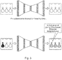
- Fig. 3 shows an autoencoder trained on healthy data. Then when the trained auroencoder is presented with heathy input data, as shown in the top image where there current carrying parts are at equivalent temperatures, the output is equivalent to the input. A comparison between the output and the input can then be used to determine that there is no fault.
- the trained autoencoder when the trained autoencoder is presented with input data, where there is a fault - for example one current carrying part is hotter than the other two - the autoencoder cannot accurately reproduce this and the output can be for example an output of three current carrying parts having each having an equivalent temperature that could be slightly higher than normal. But then a comparison between the input and the output can be used to indicate that there is a problem, because the input and output are different.
- an autoencoder could be used to detect anomalies in infrared images of electrical equipment.
- the autoencoders When trained on infrared images of healthy equipment, the autoencoders produce abnormal results when provided with images of faulty equipment. A distance metric can be used to understand if the deviation is big enough to call for an alarm.
- Autoencoders are neural networks, which reproduce the input they are given as good as they can in their output. While it would be trivial to develop an algorithm that passes on its input unchanged, autoencoders add an element of complexity. The central layers of the autoencoder are smaller than the input and output. Thus, they are forced to come up with suitable "compression techniques" in order to convey the information content.
- the autoencoder learns a "compression technique" which is optimized for its particular kind of data. For example, an autoencoder trained only on photos of green pears will find a way to compress the iconic pear shape and shades of green quite efficiently. In this compression language it is not possible to express other shapes such as red-blue checkered cubes in a satisfactory manner.
- the inventors realised that such autoencoders could be used to detect faults in medium voltage switchgear and medium voltage controlgear.
- the autoencoder is trained on IRT images of healthy electrical equipment and the autoencoder is then very be good at reproducing these images. In particular, it will exploit the correlation between the two or three phases of the system, which will be at very similar temperature levels.
- the output provided by the autoencoder is similar to the input, within limits or thresholds, and this can be used to determine that there is no fault in any of the two or three phases with respect to current carrying parts. This is shown in the top image of Fig. 3 .
- a system is provided with an infrared camera and a processor running such a trained autoencoder, which continuously records IRT images of critical sections in an electrical or electronic system such as switchgear.
- the images are fed to the autoencoder that was trained on healthy images. If the distance (a distance metric) between input and output exceeds a certain level, an anomaly alarm is triggered.
- the system can also record the images and continuously update the training of the autoencoder as alarms are acquitted as harmless - in other words use images as further training that it has determined to be healthy.
- the above is exploited by comparing the input and output images using a distance metric (such as but not limited to root squared mean error). If the distance is above a certain threshold, the image is an anomaly and an alarm is produced, and if the distance is below a metric that indicates that the input data relates to a healthy operation the image can be used to further train the autoencoder.
- the limit for the alarm and the limit for the image to be used for training can be the same or different. Thus, it may be desired to raise an alarm when a system has moved a certain amount away from being healthy, but an image may want to only be used for further training when it represents a very healthy case and where the output image is particularly similar to the input image.
- the new system only healthy data is required for training of the autoencoder, where such data is easily obtained.
- the present system is robustly trained only with healthy data
Landscapes
- Engineering & Computer Science (AREA)
- Theoretical Computer Science (AREA)
- Physics & Mathematics (AREA)
- General Physics & Mathematics (AREA)
- Data Mining & Analysis (AREA)
- Artificial Intelligence (AREA)
- Evolutionary Computation (AREA)
- General Engineering & Computer Science (AREA)
- Life Sciences & Earth Sciences (AREA)
- Multimedia (AREA)
- Computer Vision & Pattern Recognition (AREA)
- Computing Systems (AREA)
- General Health & Medical Sciences (AREA)
- Health & Medical Sciences (AREA)
- Software Systems (AREA)
- Computational Linguistics (AREA)
- Biophysics (AREA)
- Molecular Biology (AREA)
- Biomedical Technology (AREA)
- Mathematical Physics (AREA)
- Signal Processing (AREA)
- Evolutionary Biology (AREA)
- Bioinformatics & Computational Biology (AREA)
- Bioinformatics & Cheminformatics (AREA)
- Spectroscopy & Molecular Physics (AREA)
- Power Engineering (AREA)
- Quality & Reliability (AREA)
- Databases & Information Systems (AREA)
- Medical Informatics (AREA)
- Image Analysis (AREA)
- Testing Of Devices, Machine Parts, Or Other Structures Thereof (AREA)
- Emergency Alarm Devices (AREA)
Priority Applications (3)
| Application Number | Priority Date | Filing Date | Title |
|---|---|---|---|
| EP20212076.2A EP4009235A1 (fr) | 2020-12-07 | 2020-12-07 | Système de commutation ou de surveillance des appareils de commande à moyenne tension |
| CN202111478036.7A CN114663825A (zh) | 2020-12-07 | 2021-12-06 | 中压开关设备或控制设备监测系统 |
| US17/543,193 US12483010B2 (en) | 2020-12-07 | 2021-12-06 | Medium voltage switching or controlgear monitoring system |
Applications Claiming Priority (1)
| Application Number | Priority Date | Filing Date | Title |
|---|---|---|---|
| EP20212076.2A EP4009235A1 (fr) | 2020-12-07 | 2020-12-07 | Système de commutation ou de surveillance des appareils de commande à moyenne tension |
Publications (1)
| Publication Number | Publication Date |
|---|---|
| EP4009235A1 true EP4009235A1 (fr) | 2022-06-08 |
Family
ID=73740209
Family Applications (1)
| Application Number | Title | Priority Date | Filing Date |
|---|---|---|---|
| EP20212076.2A Pending EP4009235A1 (fr) | 2020-12-07 | 2020-12-07 | Système de commutation ou de surveillance des appareils de commande à moyenne tension |
Country Status (3)
| Country | Link |
|---|---|
| US (1) | US12483010B2 (fr) |
| EP (1) | EP4009235A1 (fr) |
| CN (1) | CN114663825A (fr) |
Families Citing this family (1)
| Publication number | Priority date | Publication date | Assignee | Title |
|---|---|---|---|---|
| EP4125106A1 (fr) * | 2021-07-27 | 2023-02-01 | Abb Schweiz Ag | Système de surveillance pour disjoncteur basse tension, moyenne tension ou haute tension |
Citations (2)
| Publication number | Priority date | Publication date | Assignee | Title |
|---|---|---|---|---|
| US20190197236A1 (en) * | 2017-12-27 | 2019-06-27 | Nec Laboratories America, Inc. | Reconstruction-based anomaly detection |
| EP3706267A1 (fr) * | 2019-03-07 | 2020-09-09 | ABB Schweiz AG | Système de surveillance de l'intelligence artificielle utilisant des images infrarouges pour identifier des hotspots dans un appareillage de commutation |
Family Cites Families (7)
| Publication number | Priority date | Publication date | Assignee | Title |
|---|---|---|---|---|
| US10539465B2 (en) * | 2017-03-29 | 2020-01-21 | Eaton Intelligent Power Limited | Systems, devices, and apparatus for monitoring temperature at remote locations using infrared light |
| US10474929B2 (en) * | 2017-04-25 | 2019-11-12 | Nec Corporation | Cyclic generative adversarial network for unsupervised cross-domain image generation |
| GB201811648D0 (en) * | 2018-07-16 | 2018-08-29 | Parfitt Anthony D | Electrical safety device and system |
| EP3706270B1 (fr) * | 2019-03-07 | 2022-06-29 | ABB Schweiz AG | Système de surveillance de l'intelligence artificielle utilisant des images infrarouges pour identifier des hotspots dans un appareillage de commutation |
| CN110992354B (zh) | 2019-12-13 | 2022-04-12 | 华中科技大学 | 基于引入自动记忆机制对抗自编码器的异常区域检测方法 |
| EP3859674A1 (fr) * | 2020-01-29 | 2021-08-04 | ABB Schweiz AG | Système de surveillance d'un appareillage de commutation |
| CN111967571B (zh) * | 2020-07-07 | 2023-04-21 | 华东交通大学 | 一种基于mhma的异常检测方法和设备 |
-
2020
- 2020-12-07 EP EP20212076.2A patent/EP4009235A1/fr active Pending
-
2021
- 2021-12-06 US US17/543,193 patent/US12483010B2/en active Active
- 2021-12-06 CN CN202111478036.7A patent/CN114663825A/zh active Pending
Patent Citations (2)
| Publication number | Priority date | Publication date | Assignee | Title |
|---|---|---|---|---|
| US20190197236A1 (en) * | 2017-12-27 | 2019-06-27 | Nec Laboratories America, Inc. | Reconstruction-based anomaly detection |
| EP3706267A1 (fr) * | 2019-03-07 | 2020-09-09 | ABB Schweiz AG | Système de surveillance de l'intelligence artificielle utilisant des images infrarouges pour identifier des hotspots dans un appareillage de commutation |
Non-Patent Citations (3)
| Title |
|---|
| TANG TA-WEI ET AL: "Anomaly Detection Neural Network with Dual Auto-Encoders GAN and Its Industrial Inspection Applications", SENSORS, vol. 20, no. 12, 12 June 2020 (2020-06-12), pages 3336, XP055800823, DOI: 10.3390/s20123336 * |
| WILDERMUTH STEPHAN ET AL: "Infrared temperature sensing in electrical equipment by low-cost IR cameras", 17 December 2018 (2018-12-17), pages 200 - 204, XP055803682, ISBN: 978-3-8007-4807-5, Retrieved from the Internet <URL:https://ieeexplore.ieee.org/stampPDF/getPDF.jsp?tp=&arnumber=8576742&ref=aHR0cHM6Ly9pZWVleHBsb3JlLmllZWUub3JnL2RvY3VtZW50Lzg1NzY3NDI=> [retrieved on 20210512] * |
| YONGYI RAN ET AL: "A Survey of Predictive Maintenance: Systems, Purposes and Approaches", ARXIV.ORG, CORNELL UNIVERSITY LIBRARY, 201 OLIN LIBRARY CORNELL UNIVERSITY ITHACA, NY 14853, 12 December 2019 (2019-12-12), XP081559610 * |
Also Published As
| Publication number | Publication date |
|---|---|
| CN114663825A (zh) | 2022-06-24 |
| US12483010B2 (en) | 2025-11-25 |
| US20220181856A1 (en) | 2022-06-09 |
Similar Documents
| Publication | Publication Date | Title |
|---|---|---|
| CN120031549B (zh) | 10kv变电站设备多源异构数据协同故障预测方法及其系统 | |
| CN113330463B (zh) | 在半导体设备工具中利用神经网络进行腔室匹配 | |
| US20200082245A1 (en) | Deep auto-encoder for equipment health monitoring and fault detection in semiconductor and display process equipment tools | |
| TWI841793B (zh) | 用於異常設備痕跡偵測及分類的程序及電腦可讀取媒體 | |
| US12250131B2 (en) | Method and apparatus for managing prediction of network anomalies | |
| CN112446854B (zh) | 用于监测开关设备的系统 | |
| JP2018185794A (ja) | 送電網におけるサイバー脅威を検出するための複数モデル複数領域の特徴発見 | |
| Rafique et al. | Analytics-driven fault discovery and diagnosis for cognitive root cause analysis | |
| CN119476639A (zh) | 电力多模态数据感知和数字孪生仿真协同交互方法及系统 | |
| KR102603642B1 (ko) | 연료전지 시스템의 고장 진단 방법 및 이를 수행하는 디지털 트윈 장치 | |
| US12483010B2 (en) | Medium voltage switching or controlgear monitoring system | |
| CN106841854A (zh) | 电力设备安全监控方法及系统 | |
| CN121055278A (zh) | 基于数字电网多源数据的异常检测与智能诊断方法、系统、设备及介质 | |
| CN115219039A (zh) | 用于监控设备的系统 | |
| CN111400114A (zh) | 基于深度递归网络大数据计算机系统故障检测方法及系统 | |
| CN114942364A (zh) | 一种基于知识图谱技术的变电站故障诊断方法与系统 | |
| CN116295855B (zh) | 基于无线通信网络的故障定位及诊断系统 | |
| EP4235591A1 (fr) | Système de surveillance d'un appareillage de commutation | |
| KR20230061480A (ko) | 진단 파라미터 예측 에러의 변동을 이용한 전기 장비의 상태 결정 | |
| KR20220028727A (ko) | 열화에 따른 시계열 데이터를 이용한 실시간 이상 감지 방법 및 그를 위한 장치 | |
| CN120806934B (zh) | 电力系统故障智能诊断方法、装置、设备及介质 | |
| CN120974380B (zh) | 双馈风力发电机匝间短路故障诊断方法及系统 | |
| US20260051155A1 (en) | Non-transitory computer-readable recording medium, information processing apparatus, and information processing method | |
| CN118037725B (zh) | 电气元件故障检测方法、电子设备及存储介质 | |
| CN120599390B (zh) | 基于图像处理的电气火灾监控探测方法及系统 |
Legal Events
| Date | Code | Title | Description |
|---|---|---|---|
| PUAI | Public reference made under article 153(3) epc to a published international application that has entered the european phase |
Free format text: ORIGINAL CODE: 0009012 |
|
| STAA | Information on the status of an ep patent application or granted ep patent |
Free format text: STATUS: THE APPLICATION HAS BEEN PUBLISHED |
|
| AK | Designated contracting states |
Kind code of ref document: A1 Designated state(s): AL AT BE BG CH CY CZ DE DK EE ES FI FR GB GR HR HU IE IS IT LI LT LU LV MC MK MT NL NO PL PT RO RS SE SI SK SM TR |
|
| STAA | Information on the status of an ep patent application or granted ep patent |
Free format text: STATUS: REQUEST FOR EXAMINATION WAS MADE |
|
| 17P | Request for examination filed |
Effective date: 20221024 |
|
| RBV | Designated contracting states (corrected) |
Designated state(s): AL AT BE BG CH CY CZ DE DK EE ES FI FR GB GR HR HU IE IS IT LI LT LU LV MC MK MT NL NO PL PT RO RS SE SI SK SM TR |
|
| STAA | Information on the status of an ep patent application or granted ep patent |
Free format text: STATUS: EXAMINATION IS IN PROGRESS |
|
| 17Q | First examination report despatched |
Effective date: 20240828 |