EP4009337A1 - Inducteur de puissance de type à film mince - Google Patents
Inducteur de puissance de type à film mince Download PDFInfo
- Publication number
- EP4009337A1 EP4009337A1 EP21761960.0A EP21761960A EP4009337A1 EP 4009337 A1 EP4009337 A1 EP 4009337A1 EP 21761960 A EP21761960 A EP 21761960A EP 4009337 A1 EP4009337 A1 EP 4009337A1
- Authority
- EP
- European Patent Office
- Prior art keywords
- thin
- power inductor
- coil
- magnet
- film power
- Prior art date
- Legal status (The legal status is an assumption and is not a legal conclusion. Google has not performed a legal analysis and makes no representation as to the accuracy of the status listed.)
- Pending
Links
- 239000010409 thin film Substances 0.000 claims abstract description 68
- 239000002346 layers by function Substances 0.000 claims abstract description 35
- 239000012790 adhesive layer Substances 0.000 claims abstract description 21
- 239000010410 layer Substances 0.000 claims abstract description 18
- 239000000696 magnetic material Substances 0.000 claims description 6
- 229910001004 magnetic alloy Inorganic materials 0.000 claims description 3
- 229910052751 metal Inorganic materials 0.000 claims description 3
- 239000002184 metal Substances 0.000 claims description 3
- 229910001092 metal group alloy Inorganic materials 0.000 claims description 3
- 238000000034 method Methods 0.000 description 4
- BQCADISMDOOEFD-UHFFFAOYSA-N Silver Chemical compound [Ag] BQCADISMDOOEFD-UHFFFAOYSA-N 0.000 description 2
- 238000004519 manufacturing process Methods 0.000 description 2
- 229910052709 silver Inorganic materials 0.000 description 2
- 239000004332 silver Substances 0.000 description 2
- 239000011248 coating agent Substances 0.000 description 1
- 238000000576 coating method Methods 0.000 description 1
- 230000000694 effects Effects 0.000 description 1
- 238000009713 electroplating Methods 0.000 description 1
- 230000007717 exclusion Effects 0.000 description 1
- 230000004907 flux Effects 0.000 description 1
- 238000009413 insulation Methods 0.000 description 1
- 239000000463 material Substances 0.000 description 1
- 230000035699 permeability Effects 0.000 description 1
Images


Classifications
-
- H—ELECTRICITY
- H01—ELECTRIC ELEMENTS
- H01F—MAGNETS; INDUCTANCES; TRANSFORMERS; SELECTION OF MATERIALS FOR THEIR MAGNETIC PROPERTIES
- H01F27/00—Details of transformers or inductances, in general
- H01F27/28—Coils; Windings; Conductive connections
- H01F27/2804—Printed windings
-
- H—ELECTRICITY
- H01—ELECTRIC ELEMENTS
- H01F—MAGNETS; INDUCTANCES; TRANSFORMERS; SELECTION OF MATERIALS FOR THEIR MAGNETIC PROPERTIES
- H01F27/00—Details of transformers or inductances, in general
- H01F27/28—Coils; Windings; Conductive connections
- H01F27/29—Terminals; Tapping arrangements for signal inductances
- H01F27/292—Surface mounted devices
-
- H—ELECTRICITY
- H01—ELECTRIC ELEMENTS
- H01F—MAGNETS; INDUCTANCES; TRANSFORMERS; SELECTION OF MATERIALS FOR THEIR MAGNETIC PROPERTIES
- H01F17/00—Fixed inductances of the signal type
- H01F17/0006—Printed inductances
- H01F17/0013—Printed inductances with stacked layers
-
- H—ELECTRICITY
- H01—ELECTRIC ELEMENTS
- H01F—MAGNETS; INDUCTANCES; TRANSFORMERS; SELECTION OF MATERIALS FOR THEIR MAGNETIC PROPERTIES
- H01F17/00—Fixed inductances of the signal type
- H01F17/04—Fixed inductances of the signal type with magnetic core
-
- H—ELECTRICITY
- H01—ELECTRIC ELEMENTS
- H01F—MAGNETS; INDUCTANCES; TRANSFORMERS; SELECTION OF MATERIALS FOR THEIR MAGNETIC PROPERTIES
- H01F27/00—Details of transformers or inductances, in general
- H01F27/24—Magnetic cores
-
- H—ELECTRICITY
- H01—ELECTRIC ELEMENTS
- H01F—MAGNETS; INDUCTANCES; TRANSFORMERS; SELECTION OF MATERIALS FOR THEIR MAGNETIC PROPERTIES
- H01F27/00—Details of transformers or inductances, in general
- H01F27/28—Coils; Windings; Conductive connections
- H01F27/30—Fastening or clamping coils, windings, or parts thereof together; Fastening or mounting coils or windings on core, casing, or other support
- H01F27/303—Clamping coils, windings or parts thereof together
-
- H—ELECTRICITY
- H01—ELECTRIC ELEMENTS
- H01F—MAGNETS; INDUCTANCES; TRANSFORMERS; SELECTION OF MATERIALS FOR THEIR MAGNETIC PROPERTIES
- H01F27/00—Details of transformers or inductances, in general
- H01F27/28—Coils; Windings; Conductive connections
- H01F27/30—Fastening or clamping coils, windings, or parts thereof together; Fastening or mounting coils or windings on core, casing, or other support
- H01F27/306—Fastening or mounting coils or windings on core, casing or other support
-
- H—ELECTRICITY
- H01—ELECTRIC ELEMENTS
- H01F—MAGNETS; INDUCTANCES; TRANSFORMERS; SELECTION OF MATERIALS FOR THEIR MAGNETIC PROPERTIES
- H01F27/00—Details of transformers or inductances, in general
- H01F27/28—Coils; Windings; Conductive connections
- H01F27/2804—Printed windings
- H01F2027/2809—Printed windings on stacked layers
Definitions
- Embodiments of the present application relate to the field of electronic devices, for example, a thin-film power inductor.
- An inductor (also referred to as a choke, a reactor, or a dynamic reactor) is an element that can convert electric energy into magnetic energy for storage.
- a power inductor is commonly used in a power circuit or an intelligent electronic device and may be categorized into a laminated power inductor, a thin-film power inductor, or a wire-wound power inductor.
- a puncture is required for connecting coils in a thin-film power inductor or a staggered arrangement is required for the coils in a thin-film power inductor, which make the thin-film power inductor have a complicated structure, and cause the thin-film power inductor to be manufactured difficultly.
- the present application provides a thin-film power inductor.
- the thin-film power inductor has advantages including a simple structure, a large inductance, a small direct current resistance, and an easy miniaturization.
- inventions of the present application provide a thin-film power inductor.
- the thin-film power inductor includes a magnet, a first port electrode, and a second port electrode.
- the first port electrode and the second port electrode are disposed on the outer surface of the magnet separately.
- the magnet includes at least one first sub-structure.
- a first sub-structure includes a first upper functional layer, a first upper coil, a first upper adhesive layer, a first insulating layer, a first lower adhesive layer, a first lower coil, and a first lower functional layer that are stacked in sequence.
- the first upper coil and the first lower coil each includes a first end and a second end.
- the first end of the first upper coil and the first end of the first lower coil are exposed to a same surface of the magnet and are both electrically connected to the first port electrode.
- the second end of the first upper coil and the second end of the first lower coil are exposed to a same surface of the magnet and are both electrically connected to the second port electrode.
- the processes may be performed in an order different from that described herein.
- two processes described successively may be basically implemented at a same time, or may be implemented in an order opposite to that described herein.
- FIG. 1 is a stereoscopic view of a thin-film power inductor according to embodiments of the present application.
- the thin-film power inductor includes a magnet 10, a first port electrode 20, and a second port electrode 30.
- the first port electrode 20 and the second port electrode 30 are disposed on an outer surface of the magnet 10 separately.
- the first port electrode 20 is an input electrode IN of the thin-film power inductor; the second port electrode 30 is an output electrode OUT of the thin-film power inductor.
- the first port electrode 20 and the second port electrode 30 may be formed by coating silver paste at designated ports of the magnet 10, and electroplating after the silver paste is solidified at a low temperature.
- a number of coils (also referred to as inductor coils) included in the magnet 10 may be designed according to a magnitude of an inductance of the thin-film power transistor. Specifically, the number of coils may be any positive integers.
- FIG. 2 is a section view of a first sub-structure according to embodiments of the present application.
- the first sub-structure includes a first upper functional layer A1, a first upper coil A2, a first upper adhesive layer A3, a first insulating layer A4, a first lower adhesive layer A5, a first lower coil A6, and a first lower functional layer A7 that are stacked in sequence.
- FIG. 3 is a section view of a second sub-structure according to embodiments of the present application.
- the second sub-structure includes a second functional layer B 1, a second coil B2, a second adhesive layer B3, and a second insulating layer B4 that are stacked in sequence.
- FIG. 4 is a section view of a third sub-structure according to embodiments of the present application.
- the third sub-structure includes a third upper functional layer C1, a third coil C2, a third adhesive layer C3, a third insulating layer C4, and a third lower functional layer C5 that are stacked in sequence.
- functional layers may be the first upper functional layer A1, the first lower functional layer A7, the second functional layer B1, the third upper functional layer C1, and the third lower functional layer C5.
- the functional layers may be manufactured using a same manufacturing process and may be made of a same material, and the functional layers herein are merely used for distinguishing different positions of the functional layers.
- coils may be the first upper coil A2, the first lower coil A6, the second coil B2, and the third coil C2.
- Adhesive layers may be the first upper adhesive layer A3, the first lower adhesive layer A5, the second adhesive layer B3, and the third adhesive layer C3.
- Insulating layers may be the first insulating layer A4, the second insulating layer B4, and the third insulating layer C4.
- the functional layers are configured to cover the coils, to increase an inductance of the thin-film power inductor, which is generated by self-induction of the coils.
- Each adhesive layer is configured to adhere layers on two sides of the adhesive layer to each other.
- the insulating layers are configured to guarantee insulation between the coils.
- the magnet 10 when the number of coils of the thin-film power transistor is 2n (n is a positive integer), the magnet 10 includes n first sub-structures that are stacked.
- FIG. 5 is a stereoscopic perspective view of a magnet provided with two coils according to embodiments of the present application.
- FIG. 6 is a stereoscopic perspective view of a thin-film transistor provided with two coils according to embodiments of the present application.
- the first upper coil A2 and the first lower coil A6 each includes a first end and a second end.
- the first end 111 of the first upper coil A2 and the first end 121 of the first lower coil A6 are exposed to a same surface of the magnet and are both electrically connected to the first port electrode 20.
- the second end 112 of the first upper coil A2 and the second end 122 of the first lower coil A6 are exposed to a same surface of the magnet and are both electrically connected to the second port electrode 30.
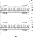
- FIG. 7 is a section view of a magnet provided with four coils according to embodiments of the present application. As shown in FIG. 7 , two first sub-structures are stacked.
- the first upper functional layer A1 and the first lower functional layer A7 adjacent to the first upper functional layer A1 may be a same layer and are formed in a same process.
- the magnet 10 when the number of coils of the thin-film power transistor is 2n + 1 (n is a positive integer), the magnet 10 includes n first sub-structures and one second sub-structure that are stacked.
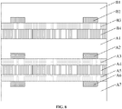
- FIG. 8 is a section view of a magnet provided with three coils according to embodiments of the present application.
- FIG. 9 is a stereoscopic perspective view of a thin-film transistor provided with three coils according to embodiments of the present application. As shown in FIGS. 8 and 9 , the magnet includes a second sub-structure and a first sub-structure that are stacked.
- the first upper coil A2, the first lower coil A6, and the second coil B2 each includes a first end and a second end.
- the first end 111 of the first upper coil A2, the first end 121 of the first lower coil A6, and the first end 131 of the second coil B2 are exposed to a same surface of the magnet and are all electrically connected to the first port electrode 20.
- the second end 112 of the first upper coil A2, the second end 122 of the first lower coil A6, and the second end 132 of the second coil B2 are exposed to the same surface of the magnet and are all electrically connected to the second port electrode 30.
- FIG. 10 is a section view of a magnet provided with five coils according to embodiments of the present application. As shown in FIG. 10 , one second sub-structure and two first sub-structures are stacked. In some embodiment, the first upper functional layer A1 and the first lower functional layer A7 adjacent to the first upper functional layer A1 may be a same layer and are formed in a same process.
- the magnet 10 when the number of coils of the thin-film power inductor is one, the magnet 10 includes one third sub-structure.
- FIG. 11 is a stereoscopic perspective view of a thin-film transistor provided with one coil according to embodiments of the present application.
- the third coil C2 includes a first end 111 and a second end 121.
- the first end 111 of the third coil C2 is exposed to the surface of the magnet and is electrically connected to the first port electrode 20.
- the second end 121 of the third coil C2 is exposed to the surface of the magnet and is electrically connected to the second port electrode 30.
- each two coils are coupled to each other and have a same shape. In this manner, the inductance of the thin-film power inductor is increased.
- the thin-film power inductor is a common-mode power inductor or a differential-mode power inductor.
- the thin-film power inductor is a common-mode power inductor.
- Each two coils are designed in the same direction. In this manner, a direct current resistance is reduced and an inductance is increased.
- the thin-film power inductor is a differential-mode power inductor. Each two coils are designed in opposite directions. In this manner, the direct current resistance is increased and the inductance is reduced.
- the functional layers of the thin-film power inductor are made of a magnetic material.
- the magnetic material for manufacturing the functional layers may be processed with insulating.
- the magnetic material may be a soft magnetic alloy.
- the soft magnetic alloy is a magnetic material with high saturation flux density, low coercive force, and high magnetic permeability.
- the coils of the thin-film power inductor may be made of a metal or a metal alloy.
- the metal or the metal alloy may have a low resistivity.
- the size of the thin-film power inductor provided in embodiments of the present application may be designed based on actual needs.
- the size of the thin-film power inductor may be 1.2 mm ⁇ 1.0 mm ⁇ 0.3 mm; a width of a coil is 100 ⁇ m; and a thickness of the coil is 30 ⁇ m.
- the present application provides a thin-film power inductor.
- the thin-film power inductor includes a magnet, a first port electrode, and a second port electrode.
- the first port electrode and the second port electrode are disposed on the outer surface of the magnet separately.
- the magnet includes at least one first sub-structure.
- a first sub-structure includes a first upper functional layer, a first upper coil, a first upper adhesive layer, a first insulating layer, a first lower adhesive layer, a first lower coil, and a first lower functional layer that are stacked in sequence.
- the first upper coil and the first lower coil each includes a first end and a second end.
- the first end of the first upper coil and the first end of the first lower coil are exposed to a same surface of the magnet and are both electrically connected to the first port electrode.
- the second end of the first upper coil and the second end of the first lower coil are exposed to a same surface of the magnet and are both electrically connected to the second port electrode.
- the thin-film power inductor Compared with a thin-film power inductor in the related art, the thin-film power inductor provided by the present application makes a full utilization of the three-dimensional multilayer space and reduces volumes required by the elements, thus having the advantages including a simple structure, a large inductance, a small direct current resistance, and an easy miniaturization.
Landscapes
- Engineering & Computer Science (AREA)
- Power Engineering (AREA)
- Microelectronics & Electronic Packaging (AREA)
- Coils Or Transformers For Communication (AREA)
Applications Claiming Priority (2)
| Application Number | Priority Date | Filing Date | Title |
|---|---|---|---|
| CN202011125941.XA CN112151246B (zh) | 2020-10-20 | 2020-10-20 | 一种薄膜型功率电感器 |
| PCT/CN2021/090466 WO2022083092A1 (fr) | 2020-10-20 | 2021-04-28 | Inducteur de puissance de type à film mince |
Publications (2)
| Publication Number | Publication Date |
|---|---|
| EP4009337A1 true EP4009337A1 (fr) | 2022-06-08 |
| EP4009337A4 EP4009337A4 (fr) | 2023-11-29 |
Family
ID=73954101
Family Applications (1)
| Application Number | Title | Priority Date | Filing Date |
|---|---|---|---|
| EP21761960.0A Pending EP4009337A4 (fr) | 2020-10-20 | 2021-04-28 | Inducteur de puissance de type à film mince |
Country Status (4)
| Country | Link |
|---|---|
| US (1) | US20230360839A1 (fr) |
| EP (1) | EP4009337A4 (fr) |
| CN (1) | CN112151246B (fr) |
| WO (1) | WO2022083092A1 (fr) |
Families Citing this family (1)
| Publication number | Priority date | Publication date | Assignee | Title |
|---|---|---|---|---|
| CN112151246B (zh) * | 2020-10-20 | 2025-05-30 | 横店集团东磁股份有限公司 | 一种薄膜型功率电感器 |
Family Cites Families (26)
| Publication number | Priority date | Publication date | Assignee | Title |
|---|---|---|---|---|
| TW200717549A (en) * | 2005-10-14 | 2007-05-01 | Murata Manufacturing Co | Multiplayer coil component |
| CN101840768B (zh) * | 2009-03-20 | 2012-07-04 | 佳邦科技股份有限公司 | 薄膜式共模噪声滤波器的结构与制造方法 |
| JP5451791B2 (ja) * | 2012-02-08 | 2014-03-26 | 太陽誘電株式会社 | 積層インダクタ |
| CN102867634A (zh) * | 2012-05-07 | 2013-01-09 | 深圳市固电电子有限公司 | 叠层片式电感器 |
| JP6312997B2 (ja) * | 2013-07-31 | 2018-04-18 | 新光電気工業株式会社 | コイル基板及びその製造方法、インダクタ |
| KR101973410B1 (ko) * | 2013-08-14 | 2019-09-02 | 삼성전기주식회사 | 박막 인덕터용 코일 유닛, 박막 인덕터용 코일 유닛의 제조방법, 박막 인덕터 및 박막 인덕터의 제조방법 |
| KR101983150B1 (ko) * | 2013-10-11 | 2019-05-28 | 삼성전기주식회사 | 적층형 인덕터 및 그 제조 방법 |
| KR20150114747A (ko) * | 2014-04-02 | 2015-10-13 | 삼성전기주식회사 | 칩형 코일 부품 및 그 실장 기판 |
| KR102120898B1 (ko) * | 2014-06-19 | 2020-06-09 | 삼성전기주식회사 | 칩형 코일 부품 |
| KR102185067B1 (ko) * | 2014-09-24 | 2020-12-01 | 삼성전기주식회사 | 박막 인덕터용 코일 유닛, 박막 인덕터용 코일 유닛의 제조방법, 박막 인덕터 및 박막 인덕터의 제조방법 |
| KR102178531B1 (ko) * | 2015-01-28 | 2020-11-13 | 삼성전기주식회사 | 칩 전자부품 및 칩 전자부품의 실장 기판 |
| CN106449012B (zh) * | 2015-08-11 | 2018-09-18 | 佳邦科技股份有限公司 | 定制化表面黏着型功率电感器及其制作方法 |
| KR102558332B1 (ko) * | 2016-05-04 | 2023-07-21 | 엘지이노텍 주식회사 | 인덕터 및 이의 제조 방법 |
| KR102632366B1 (ko) * | 2016-09-01 | 2024-02-02 | 삼성전기주식회사 | 코일 부품 |
| JP6589793B2 (ja) * | 2016-09-26 | 2019-10-16 | 株式会社村田製作所 | 積層型電子部品 |
| KR101868026B1 (ko) * | 2016-09-30 | 2018-06-18 | 주식회사 모다이노칩 | 파워 인덕터 |
| KR101823267B1 (ko) * | 2016-11-01 | 2018-01-29 | 삼성전기주식회사 | 박막 인덕터 및 그 제조 방법 |
| JP6658681B2 (ja) * | 2017-06-22 | 2020-03-04 | 株式会社村田製作所 | 積層インダクタの製造方法および積層インダクタ |
| KR101952873B1 (ko) * | 2017-07-05 | 2019-02-27 | 삼성전기주식회사 | 박막형 인덕터 |
| KR102442385B1 (ko) * | 2017-07-05 | 2022-09-14 | 삼성전기주식회사 | 박막형 인덕터 |
| KR102016499B1 (ko) * | 2018-04-10 | 2019-09-02 | 삼성전기주식회사 | 코일 부품 |
| KR102109636B1 (ko) * | 2018-07-19 | 2020-05-12 | 삼성전기주식회사 | 칩 인덕터 및 그 제조방법 |
| JP7218589B2 (ja) * | 2019-01-28 | 2023-02-07 | Tdk株式会社 | コイル部品 |
| US20220037083A1 (en) * | 2020-07-31 | 2022-02-03 | Taiyo Yuden Co., Ltd. | Inductor array |
| CN112151246B (zh) * | 2020-10-20 | 2025-05-30 | 横店集团东磁股份有限公司 | 一种薄膜型功率电感器 |
| CN213070861U (zh) * | 2020-10-20 | 2021-04-27 | 横店集团东磁股份有限公司 | 一种薄膜型功率电感器 |
-
2020
- 2020-10-20 CN CN202011125941.XA patent/CN112151246B/zh active Active
-
2021
- 2021-04-28 WO PCT/CN2021/090466 patent/WO2022083092A1/fr not_active Ceased
- 2021-04-28 US US17/611,468 patent/US20230360839A1/en active Pending
- 2021-04-28 EP EP21761960.0A patent/EP4009337A4/fr active Pending
Also Published As
| Publication number | Publication date |
|---|---|
| US20230360839A1 (en) | 2023-11-09 |
| CN112151246B (zh) | 2025-05-30 |
| EP4009337A4 (fr) | 2023-11-29 |
| CN112151246A (zh) | 2020-12-29 |
| WO2022083092A1 (fr) | 2022-04-28 |
Similar Documents
| Publication | Publication Date | Title |
|---|---|---|
| US11532424B2 (en) | Inductance element and electronic device | |
| US8373534B2 (en) | Flexible coil | |
| US8717136B2 (en) | Inductor with laminated yoke | |
| EP2652755B1 (fr) | Inductance à film mince avec entrefers intégrés | |
| US20140167897A1 (en) | Power inductor and method of manufacturing the same | |
| US20240379277A1 (en) | Multi-phase coupled inductor and manufacturing method thereof | |
| US20070057755A1 (en) | Solid electrolytic capacitor and manufacturing method thereof | |
| US20130241684A1 (en) | Method for manufacturing common mode filter and common mode filter | |
| US12334239B2 (en) | Patterned magnetic cores | |
| US20250210249A1 (en) | Inductor array | |
| US9019059B2 (en) | Multi-turn high density coil and fabrication method | |
| CN213070861U (zh) | 一种薄膜型功率电感器 | |
| EP4009337A1 (fr) | Inducteur de puissance de type à film mince | |
| KR101338139B1 (ko) | 파워 인덕터 | |
| CN220672356U (zh) | 一种电感器 | |
| CN212907274U (zh) | 新型电磁铁及扬声器的磁性结构 | |
| CN117594332A (zh) | 线圈部件 | |
| CN114334333A (zh) | 一种电磁元件与电子设备 | |
| JP2022126115A (ja) | 積層コイル部品 | |
| US20230008016A1 (en) | Coil component | |
| JP4724940B2 (ja) | 積層型インダクタンス素子及び積層型インダクタンス素子の製造方法 | |
| JP2002043139A (ja) | 薄型インダクタ | |
| CN121331615A (zh) | 平面变压器及其适用的电源供应器 | |
| KR20190067513A (ko) | 박막형 코일 부품 | |
| KR20230157636A (ko) | 코일 부품 |
Legal Events
| Date | Code | Title | Description |
|---|---|---|---|
| STAA | Information on the status of an ep patent application or granted ep patent |
Free format text: STATUS: UNKNOWN |
|
| STAA | Information on the status of an ep patent application or granted ep patent |
Free format text: STATUS: THE INTERNATIONAL PUBLICATION HAS BEEN MADE |
|
| PUAI | Public reference made under article 153(3) epc to a published international application that has entered the european phase |
Free format text: ORIGINAL CODE: 0009012 |
|
| STAA | Information on the status of an ep patent application or granted ep patent |
Free format text: STATUS: REQUEST FOR EXAMINATION WAS MADE |
|
| 17P | Request for examination filed |
Effective date: 20210906 |
|
| AK | Designated contracting states |
Kind code of ref document: A1 Designated state(s): AL AT BE BG CH CY CZ DE DK EE ES FI FR GB GR HR HU IE IS IT LI LT LU LV MC MK MT NL NO PL PT RO RS SE SI SK SM TR |
|
| REG | Reference to a national code |
Ref country code: DE Ref legal event code: R079 Free format text: PREVIOUS MAIN CLASS: H01F0027290000 Ipc: H01F0017000000 |
|
| A4 | Supplementary search report drawn up and despatched |
Effective date: 20231026 |
|
| RIC1 | Information provided on ipc code assigned before grant |
Ipc: H01F 27/29 20060101ALI20231020BHEP Ipc: H01F 17/04 20060101ALI20231020BHEP Ipc: H01F 17/00 20060101AFI20231020BHEP |
|
| DAV | Request for validation of the european patent (deleted) | ||
| DAX | Request for extension of the european patent (deleted) |