EP4009342A2 - Disjoncteur avec un ensemble de soufflage magnétique - Google Patents
Disjoncteur avec un ensemble de soufflage magnétique Download PDFInfo
- Publication number
- EP4009342A2 EP4009342A2 EP21207794.5A EP21207794A EP4009342A2 EP 4009342 A2 EP4009342 A2 EP 4009342A2 EP 21207794 A EP21207794 A EP 21207794A EP 4009342 A2 EP4009342 A2 EP 4009342A2
- Authority
- EP
- European Patent Office
- Prior art keywords
- magnetization
- arc
- chamber
- base body
- movable contactor
- Prior art date
- Legal status (The legal status is an assumption and is not a legal conclusion. Google has not performed a legal analysis and makes no representation as to the accuracy of the status listed.)
- Ceased
Links
- 230000005415 magnetization Effects 0.000 claims abstract description 151
- 230000003068 static effect Effects 0.000 claims abstract description 47
- 239000004020 conductor Substances 0.000 claims abstract description 22
- 230000005540 biological transmission Effects 0.000 claims description 9
- 239000000463 material Substances 0.000 claims description 8
- 238000006073 displacement reaction Methods 0.000 claims description 7
- 238000009413 insulation Methods 0.000 claims description 6
- 238000010586 diagram Methods 0.000 description 10
- 230000000694 effects Effects 0.000 description 2
- 229910000976 Electrical steel Inorganic materials 0.000 description 1
- 239000004677 Nylon Substances 0.000 description 1
- 238000002679 ablation Methods 0.000 description 1
- 230000004913 activation Effects 0.000 description 1
- 230000001154 acute effect Effects 0.000 description 1
- 238000007664 blowing Methods 0.000 description 1
- 239000012141 concentrate Substances 0.000 description 1
- 230000002708 enhancing effect Effects 0.000 description 1
- 239000008187 granular material Substances 0.000 description 1
- 239000012774 insulation material Substances 0.000 description 1
- 238000000034 method Methods 0.000 description 1
- 229920001778 nylon Polymers 0.000 description 1
- 229920001169 thermoplastic Polymers 0.000 description 1
- 229920001187 thermosetting polymer Polymers 0.000 description 1
- 239000004416 thermosoftening plastic Substances 0.000 description 1
Images





Classifications
-
- H—ELECTRICITY
- H01—ELECTRIC ELEMENTS
- H01H—ELECTRIC SWITCHES; RELAYS; SELECTORS; EMERGENCY PROTECTIVE DEVICES
- H01H9/00—Details of switching devices, not covered by groups H01H1/00 - H01H7/00
- H01H9/30—Means for extinguishing or preventing arc between current-carrying parts
- H01H9/44—Means for extinguishing or preventing arc between current-carrying parts using blow-out magnet
- H01H9/446—Means for extinguishing or preventing arc between current-carrying parts using blow-out magnet using magnetisable elements associated with the contacts
-
- H—ELECTRICITY
- H01—ELECTRIC ELEMENTS
- H01H—ELECTRIC SWITCHES; RELAYS; SELECTORS; EMERGENCY PROTECTIVE DEVICES
- H01H1/00—Contacts
- H01H1/12—Contacts characterised by the manner in which co-operating contacts engage
- H01H1/14—Contacts characterised by the manner in which co-operating contacts engage by abutting
- H01H1/22—Contacts characterised by the manner in which co-operating contacts engage by abutting with rigid pivoted member carrying the moving contact
- H01H1/221—Contacts characterised by the manner in which co-operating contacts engage by abutting with rigid pivoted member carrying the moving contact and a contact pressure spring acting between the pivoted member and a supporting member
-
- H—ELECTRICITY
- H01—ELECTRIC ELEMENTS
- H01H—ELECTRIC SWITCHES; RELAYS; SELECTORS; EMERGENCY PROTECTIVE DEVICES
- H01H77/00—Protective overload circuit-breaking switches operated by excess current and requiring separate action for resetting
- H01H77/02—Protective overload circuit-breaking switches operated by excess current and requiring separate action for resetting in which the excess current itself provides the energy for opening the contacts, and having a separate reset mechanism
- H01H77/10—Protective overload circuit-breaking switches operated by excess current and requiring separate action for resetting in which the excess current itself provides the energy for opening the contacts, and having a separate reset mechanism with electrodynamic opening
- H01H77/107—Protective overload circuit-breaking switches operated by excess current and requiring separate action for resetting in which the excess current itself provides the energy for opening the contacts, and having a separate reset mechanism with electrodynamic opening characterised by the blow-off force generating means, e.g. current loops
- H01H77/108—Protective overload circuit-breaking switches operated by excess current and requiring separate action for resetting in which the excess current itself provides the energy for opening the contacts, and having a separate reset mechanism with electrodynamic opening characterised by the blow-off force generating means, e.g. current loops comprising magnetisable elements, e.g. flux concentrator, linear slot motor
-
- H—ELECTRICITY
- H01—ELECTRIC ELEMENTS
- H01H—ELECTRIC SWITCHES; RELAYS; SELECTORS; EMERGENCY PROTECTIVE DEVICES
- H01H9/00—Details of switching devices, not covered by groups H01H1/00 - H01H7/00
- H01H9/30—Means for extinguishing or preventing arc between current-carrying parts
- H01H9/302—Means for extinguishing or preventing arc between current-carrying parts wherein arc-extinguishing gas is evolved from stationary parts
-
- H—ELECTRICITY
- H01—ELECTRIC ELEMENTS
- H01H—ELECTRIC SWITCHES; RELAYS; SELECTORS; EMERGENCY PROTECTIVE DEVICES
- H01H9/00—Details of switching devices, not covered by groups H01H1/00 - H01H7/00
- H01H9/30—Means for extinguishing or preventing arc between current-carrying parts
- H01H9/34—Stationary parts for restricting or subdividing the arc, e.g. barrier plate
- H01H9/346—Details concerning the arc formation chamber
Definitions
- the present utility model relates to a low-voltage electrical appliance, and in particular to a circuit breaker.
- a circuit breaker mainly includes a base, and a movable contactor, a static contactor, and an arc extinguishing chamber mounted on the base.
- a movable contact of the movable contactor is connected to or disconnected from a static contact of the static contactor, so that a current is allowed to pass or is cut off.
- the movable contactor separates from the static contactor under the action of a protection unit, thereby generating an arc.
- the arc is quickly transferred from a position between the movable contactor and the static contactor to the arc extinguishing chamber.
- the above objective is usually achieved by means of magnetic blow-out, a gas blast, and the like in the prior art.
- a device or material for magnetic blow-out and a gas blast is usually arranged on a side of an arc to be generated close to an arc extinguishing chamber, for example, in the arc extinguishing chamber.
- the arc needs to move by a certain distance before being affected by a magnetic field or a gas.
- the present utility model provides a circuit breaker.
- a magnetization assembly applies, on a side of an arc facing away from an arc extinguishing chamber, to the arc an electromagnetic force towards the arc extinguishing chamber, so as to further urge the arc to move towards the arc extinguishing chamber, thereby improving a speed at which the arc is transferred from a contactor to the arc extinguishing chamber.
- the present utility model provides a circuit breaker.
- the circuit breaker comprises a base extending at least partially in a horizontal direction, and further comprises an arc extinguishing chamber, a static contactor, a movable contactor, and a magnetization assembly.
- the arc extinguishing chamber is fixedly mounted to the base.
- the static contactor comprises a forward base body extending in a longitudinal direction and fixedly connected, below the arc extinguishing chamber, to a horizontally extending region of the base, the static contactor further comprises a reverse base body extending upwards from one longitudinal end of the forward base body, and then extending, opposite to the forward base body, until a free end thereof reaches a side of the arc extinguishing chamber, wherein a static contact is provided on an upper surface of the reverse base body, and an arc guiding member leading to the arc extinguishing chamber is mounted at the free end of the reverse base body.
- the movable contactor comprises a movable contact, and is designed to be rotatably arranged above the reverse base body relative to the base by means of a driving mechanism and a transmission mechanism so as to engage with or disengage from the static contact by means of the movable contact.
- the magnetization assembly comprises a first magnetization chamber and a second magnetization chamber both made of a non-electrically and non-magnetically conductive material, the first magnetization chamber and the second magnetization chamber being arranged opposite each other on two lateral sides of the reverse base body, the first magnetization chamber and the second magnetization chamber extending and covering at least part of the static contact in a longitudinal direction of the reverse base body and extending vertically at least beyond the static contact so as to allow at least part of an arc generated between the static contact and the movable contact to fall into a space defined by the first magnetization chamber and the second magnetization chamber, the magnetization assembly further comprising a magnetically conductive material, and the magnetically conductive material being arranged in cavities of the first magnetization chamber and the second magnetization chamber.
- the circuit breaker having the configuration described above is capable of applying, on a side of an arc facing away from the arc extinguishing chamber, to the arc an electromagnetic force towards the arc extinguishing chamber, and is capable of applying a greater Ampere force to the arc.
- the magnetization assembly further comprises a third magnetization chamber, the third magnetization chamber being also made of a non-electrically and non-magnetically conductive material, and the third magnetization chamber being designed to be arranged vertically between the forward base body and the reverse base body and arranged between the first magnetization chamber and the second magnetization chamber in a lateral direction of the reverse base body so as to connect the first magnetization chamber and the second magnetization chamber, wherein cavities of the first magnetization chamber, the second magnetization chamber, and the third magnetization chamber communicate with each other and collectively constitute a U-shaped cavity, and the magnetically conductive material is superposed in the form of a U-shaped magnetization sheet in the longitudinal direction of the reverse base body, and is conformably accommodated in the U-shaped cavity.
- the third magnetization cavity is capable of further enhancing magnetic field intensity in an arc region.
- the magnetization assembly further comprises a support portion also made of a non-electrically and non-magnetically conductive material, the support portion comprising a support main body designed to extend from the third magnetization chamber towards the other longitudinal end of the forward base body until reaching or beyond the free end of the reverse base body, wherein the support main body is vertically dimensioned to allow a lower surface thereof to rest against an upper surface of the forward base body and to allow a lower surface of the reverse base body to rest against an upper surface thereof.
- the support portion having the configuration described above is capable of preventing the free end of the reverse base body from deforming vertically.
- the support portion further comprises two lateral limiting protrusions extending from the upper surface of the support main body, a lateral dimension between the two lateral limiting protrusions being designed to allow at least the free end of the reverse base body to be accommodated therein to prevent lateral displacement of the free end of the reverse base body, the support portion further comprising a positioning boss extending from the lower surface of the support main body, and a positioning notch being provided on the upper surface of the forward base body, wherein the positioning notch is dimensioned to allow the positioning boss to be inserted therein so as to limit displacement of the support portion relative to the static contactor.
- the support portion having the configuration described above is capable of preventing the free end of the reverse base body from deforming laterally.
- At least part of a housing of one or more of the first magnetization chamber, the second magnetization chamber, and the third magnetization chamber is made of a gas-producing material.
- the first magnetization chamber, the second magnetization chamber, the third magnetization chamber, and the support portion are a unitary piece, wherein insulation paper is provided between the magnetization assembly and the upper surface of the forward base body.
- the transmission mechanism comprises a mounting chassis, a movable contactor support, a spring, an upper spring shaft, a lower spring shaft, and a mounting screw
- the mounting chassis comprises a fixed portion fixedly connected to the base and an annular mounting member extending from the fixed portion towards the movable contactor support
- the movable contactor support is configured to comprise a first support plate and a second support plate arranged on two sides of the annular mounting member and extending parallel to each other, an end portion of the movable contactor distal to the movable contact thereof is arranged between the first support plate and the annular mounting member and/or between the second support plate and the annular mounting member
- a movable contactor rotating hole is provided at the end portion of the movable contactor distal to the movable contact thereof
- a first rotating hole is provided on the first support plate, a second rotating hole being provided on the second support plate
- the movable contactor rotating hole, the first rotating hole, and the second rotating hole is relatively rotatably and closely
- an upper edge of the first support plate comprises a first upper curved recessed section and a first upper arc-shaped protruding section extending immediately following the first upper curved recessed section; a lower edge of the first support plate comprises a first lower arc-shaped recessed section; an upper edge of the second support plate comprises a second upper curved recessed section and a second upper arc-shaped protruding section extending immediately following the second upper curved recessed section; a lower edge of the second support plate comprises a second lower arc-shaped recessed section; the movable contactor is provided with a slot between the movable contact and the movable contactor rotating hole; the upper spring shaft is designed to pass through the slot and have two ends overlapping with the first upper curved recessed section and the second upper curved recessed section; the lower spring shaft is designed to be accommodated in the first lower arc-shaped recessed section edge and the second lower arc-shaped recessed section; the lower spring shaft is connected to the upper spring shaft by means of the spring; wherein
- the first upper curved recessed section and the second upper curved recessed section are arranged symmetrically about the annular mounting member; the first upper arc-shaped protruding section and the second upper arc-shaped protruding section are arranged symmetrically about the annular mounting member; the first lower arc-shaped recessed section and the second lower arc-shaped recessed section are arranged symmetrically about the annular mounting member.
- the movable contactor comprises a first movable contactor element and a second movable contactor element, wherein an end portion of the first movable contactor element distal to the movable contact thereof is clamped between the first support plate and the annular mounting member; an end portion of the second movable contactor element distal to the movable contact thereof is clamped between the second support plate and the annular mounting member; the spring is arranged between the first movable contactor element and the second movable contactor element; shaft sleeves are respectively provided at two ends of the upper spring shaft; a first driving hole and a second driving hole are respectively provided on the first support plate and the second support plate; the driving mechanism drives, by means of the first driving hole and the second driving hole, the movable contactor support to rotate relative to the mounting chassis.
- first support plate 611. first rotating hole; 612. first upper curved recessed section; 613. first upper arc-shaped protruding section; 614. first lower arc-shaped recessed section; 615. first driving hole; 62. second support plate; 621. second upper curved recessed section; 622. second upper arc-shaped protruding section; 63. mounting screw; 7. spring; 8. upper spring shaft; 9. lower spring shaft; 10. shaft sleeve.
- the present utility model provides a circuit breaker.
- the circuit breaker includes a base (not shown), an arc extinguishing chamber 4, a static contactor 2, and a movable contactor 3, and reference may be made to FIG. 1 for positions where the four components are arranged.
- the arc extinguishing chamber 4 mainly includes an arc extinguishing grate sheet and a mounting side plate. For clarity of illustration, the mounting side plate is not shown herein. Specifically, the arc extinguishing chamber 4 is fixedly mounted to the base.
- the static contactor 2 includes a forward base body 21 and a reverse base body 22. The base has at least one region extending horizontally.
- the forward base body 21 is arranged below the arc extinguishing chamber 4, and is fixedly connected to the horizontally extending region of the base.
- the forward base body 21 extends in a longitudinal direction thereof.
- the reverse base body 22 extends upwards from one longitudinal end of the forward base body 21, and then extends opposite to the forward base body 21 until a free end thereof reaches a side of the arc extinguishing chamber 4. It is noted here that the reverse base body 22 extending opposite to the forward base body 21 does not indicate that extension directions of the reverse base body 22 and the forward base body 21 are absolutely parallel.
- the reverse base body 22 may be inclined upwards or downwards relative to the forward base body 21, and an acute angle may be formed therebetween.
- An arc guiding member 24 leading to the arc extinguishing chamber 4 is mounted at the free end of the reverse base body 22, and facilitates guiding of an arc generated between the static contactor 2 and the movable contactor 3 into the arc extinguishing chamber 4.
- the static contactor 23 is arranged on an upper surface of the reverse base body 22 so as to contact a movable contact 33 of the movable contactor 3.
- the movable contactor 3 is also mounted to the base, is arranged above the reverse base body 22 by means of a driving mechanism (not shown) and a transmission mechanism that will be described in detail below, and can rotate about the base.
- the movable contactor 3 has the movable contact 33.
- the movable contactor 3 rotates about the base, so that the movable contact 33 can contact or be separated from the static contact 23, so as to cause a circuit to be closed or open.
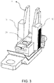
- the present utility model provides a magnetization assembly 1.
- the magnetization assembly 1 can apply to the arc an electromagnetic force on a side surface of the arc distal to the arc extinguishing chamber 4 when the generated arc is used as a demarcation line, so as to urge the arc enter the arc extinguishing chamber 4.
- the magnetization assembly 1 is configured to include at least a first magnetization chamber 11 and a second magnetization chamber 12, and both of the two chambers are made of a non-electrically and non-magnetically conductive material (e. g., thermoplastic or thermoset).
- a non-electrically and non-magnetically conductive material e. g., thermoplastic or thermoset.
- the first magnetization chamber 11 and the second magnetization chamber 12 are arranged on two lateral sides of the reverse base body 22, and are opposite each other. In order to ensure that an as great as possible Ampere force can be applied to the generated arc, at least part of the arc needs to fall into a space defined by the first magnetization chamber 11 and the second magnetization chamber 12.
- the first magnetization chamber 11 and the second magnetization chamber 12 need to extend and cover at least part of the static contact 23 in a longitudinal direction of the reverse base body 22, and in addition, the first magnetization chamber 11 and the second magnetization chamber 12 need to extend vertically at least beyond the static contact 23, preferably extend vertically beyond the static contact as much as possible, and most preferably cover the movable contactor repelled from the static contactor.
- the first magnetization chamber 11 and the second magnetization chamber 12 can be connected to the static contactor 2 by means of, for example, an additional securing means.
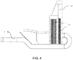
- the magnetization assembly 1 also includes a magnetically conductive material, such as a silicon steel sheet, and the magnetically conductive material is arranged in cavities of the first magnetization chamber 11 and the second magnetization chamber 12.
- the magnetically conductive material can concentrate an ambient magnetic field, and apply the same to an arc section falling within the space defined by the first magnetization chamber 11 and the second magnetization chamber 12.
- the magnetically conductive material can be placed in the cavities of the first magnetization chamber 11 and the second magnetization chamber 12 in the form of, for example, a grate sheet (also referred to as a magnetization sheet), granules, blocks, or the like.
- the magnetization assembly further includes a third magnetization chamber 13 also made of a non-electrically and non-magnetically conductive material.
- the third magnetization chamber 13 is arranged vertically between the forward base body 21 and the reverse base body 22, and is arranged between the first magnetization chamber 11 and the second magnetization chamber 12 in a lateral direction of the reverse base body 22 so as to cause the first magnetization chamber 11 and the second magnetization chamber 12 to be connected to each other.
- outer profiles of the first magnetization chamber 11, the second magnetization chamber 12, and the third magnetization chamber 13 can collectively form a U shape.
- the third magnetization chamber 13 likewise can be filled with a magnetically conductive material.
- Cavities of the first magnetization chamber 11, the second magnetization chamber 12, and the third magnetization chamber 13 communicate with each other, and collectively constitute a U-shaped cavity, so that at least part of the arc is enclosed by the U-shaped cavity.
- the magnetically conductive material is preferably designed to be in the form of a U-shaped magnetization sheet 15.
- a plurality of U-shaped magnetization sheets 15 can be superposed in the longitudinal direction of the reverse base body 22, and is conformably accommodated in the U-shaped cavity.
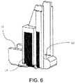
- the magnetization assembly 1 further includes a support portion 14.
- the support portion 14 is likewise made of a non-electrically and non-magnetically conductive material.
- the support portion 14 is designed to include a support main body 141, two lateral limiting protrusions 142 respectively extending upwards and downwards from the support main body 141, and a positioning boss 143.
- the support main body 141 is also arranged between the forward base body 21 and the reverse base body 22, and serves to fill a vertical space between the forward base body 21 and the reverse base body 22.
- the support main body 141 extends from the third magnetization chamber 13 towards the other longitudinal end of the forward base body 21 until reaching or even beyond the free end of the reverse base body 22.
- a lower surface of the support main body 141 vertically rests against an upper surface of the forward base body 21, and a lower surface of the reverse base body 22 can also rest against an upper surface of the support main body 141.
- the free end of the reverse base body 22 is highly prone to deform, and for example, the reverse base body 22 is displaced a certain distance vertically towards the forward base body 21.
- the support main body 141 can support the reverse base body 22 from vertically below the reverse base body 22, thereby preventing vertical downward displacement of the free end of the reverse base body 22.
- the two lateral limiting protrusions 142 extend from the upper surface of the reverse base body 22.
- a lateral distance between the two lateral limiting protrusions 142 needs be designed to allow the reverse base body 22, in particular the free end of the reverse base body 22, to be accommodated therein.
- the two lateral sides of the reverse base body 22 can respectively rest against the two lateral limiting protrusions 142, thereby limiting lateral displacement of the reverse base body 22.
- the first magnetization chamber 11, the second magnetization chamber 12, the third magnetization chamber 13, and the support portion 14 are preferably a unitary piece.
- the positioning boss 143 described above extends from the lower surface of the support main body 141.
- a positioning notch 25 (see FIG. 1 ) is also correspondingly provided on the upper surface of the forward base body 21. This positioning notch 25 is positioned and dimensioned to allow the positioning boss 143 to be inserted therein, thereby limiting movement of the support portion 14 relative to the static contactor, and further limiting movement of the entire magnetization assembly 1 relative to the static contactor 2.
- housings of the first, second, and third magnetization chambers distal to the reverse base body 22 may be partially open, and the U-shaped magnetization sheet 15 may be exposed to the outside, thereby simplifying a structure and a mounting process.
- an insulation material such as an insulation tape needs to be wrapped around the U-shaped magnetization sheet from the outside of the housing so as to prevent the U-shaped magnetization sheet from directly contacting the static contactor.
- insulation paper26 is provided between the magnetization assembly 1 and the upper surface of the forward base body 21 so as to further prevent the magnetization sheet from directly contacting the static contactor 2, thereby increasing an electrical gap of a product.
- the insulation paper 26 may also be provided to protect the static contactor below the arc extinguishing chamber from arc ablation.
- part of the housing of one or more of the first magnetization chamber 11, the second magnetization chamber 12, and the third magnetization chamber 13 may be made of a gas-producing material 16, for example nylon, and reference may be made to FIG. 5 for an exemplary position thereof. It is also preferred that all of the entire housing of the first magnetization chamber 11, the second magnetization chamber 12, and the third magnetization chamber 13 is made of the gas-producing material.
- the gas-producing material 16 produces a gas, thereby blowing the arc to move towards the arc extinguishing chamber 4. Additionally, the produced gas can also effectively cool the arc, lengthen the arc, and raise the arc voltage, thereby facilitating extinguishing of the arc.
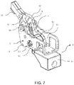
- the transmission mechanism is a mechanism designed to be driven by the driving mechanism so as to drive the movable contactor 3 to rotate relative to the base, and has another function herein, that is, holding the repelled movable contactor 3.
- the transmission mechanism mainly includes a mounting chassis 5, a movable contactor support 6, a spring 7, an upper spring shaft 8, a lower spring shaft 9, and a mounting screw 63.
- the mounting chassis 5 includes a fixed portion 51 and an annular mounting member 52.
- the fixed portion 51 is fixedly connected to the base, in particular a portion of the base extending horizontally.
- the annular mounting member 52 is designed to extend from the fixed portion 51 towards the movable contactor support 6 so that the movable contactor 3 and the movable contactor support 6 are connected thereto.
- the movable contactor support 6 mainly includes a first support plate 61 and a second support plate 62.
- the first support plate 61 and the second support plate 62 extend parallel to each other, and are arranged on two sides of the annular mounting member 52.
- the movable contactor 3 is arranged between the first support plate 61 and the second support plate 62. More specifically, when the movable contactor 3 is designed as shown in FIG.
- first movable contactor element 31 and a second movable contactor element 32 an end portion of the first movable contactor element 31 distal to the movable contact 33 is held between the first support plate 61 and the annular mounting member 52, and an end portion of the second movable contactor element 32 distal to the movable contact 33 is held between the second support plate 62 and the annular mounting member 52.
- a movable contactor rotating hole 34 is provided at an end portion of the movable contactor 3 (the first movable contactor element 31 and/or the second movable contactor element 32) distal to the movable contact 33.
- a first rotating hole 611 is provided on the first support plate 61.
- a second rotating hole is provided on the second support plate 62.
- a mounting screw 63 is provided.
- the movable contactor rotating hole 34, the first rotating hole 611, and the second rotating hole can be connected to each other by means of the mounting screws 63 respectively passing therethrough, so that the first support plate 61, the second support plate 62, the movable contactor 3, and the annular mounting member 52 are connected to each other, and can rotate relative to each other.
- the mounting screws 63 needs to be tightened sufficiently to ensure that the first support plate 61, the second support plate 62, the movable contactor 3, and the annular mounting member 52 are closely connected to each other.
- a connection between the movable contactor 3 and the annular mounting member 52 is mostly a soft connection.
- the soft connection generates great resistance to movement of the movable contactor 3.
- a hard screw is used herein, thereby achieving the technical effect of increasing an activation speed of the movable contactor 3.
- an upper edge of the first support plate 61 includes a first upper curved recessed section 612 and a first upper arc-shaped protruding section 613.
- the first upper arc-shaped protruding section 613 extends immediately following the first upper curved recessed section 612.
- An upper edge of the second support plate 62 includes a second upper curved recessed section 621 and a second upper arc-shaped protruding section 622.
- the second upper arc-shaped protruding section 622 extends immediately following the second upper curved recessed section 621.
- a lower edge of the first support plate 61 includes a first lower arc-shaped recessed section 614.
- the first lower arc-shaped recessed section 614 and the first upper arc-shaped protruding section 613 are designed to be concentric, as schematically illustrated in FIG. 10 .
- a lower edge of the second support plate 62 includes a second lower arc-shaped recessed section (not shown), and the second lower arc-shaped recessed section and the second upper arc-shaped protruding section 622 are also designed to be concentric.
- the movable contactor 3 is provided with a slot 35 between the movable contact 33 and the movable contactor rotating hole 34.
- the upper spring shaft 8 can pass through the slot 35 of the movable contactor 3, and has two ends overlapping with the first upper curved recessed section 612 and the second upper curved recessed section 621.
- the lower spring shaft 9 is accommodated in the first lower arc-shaped recessed section 614 and the second lower arc-shaped recessed section.
- the lower spring shaft 9 is connected to the upper spring shaft 8 by means of the spring 7.
- the upper spring shaft 8 moves within the first upper curved recessed section 612 and the second upper curved recessed section 621.
- the first upper arc-shaped protruding section 613 may be dimensioned to allow the upper spring shaft 8 to disengage from the first upper curved recessed section 612 and continue to move along the first upper arc-shaped protruding section 613.
- the second upper arc-shaped protruding section 622 may be dimensioned to allow the upper spring shaft 8 to disengage from the second upper curved recessed section 621 and continue to move along the second upper arc-shaped protruding section 622.
- the lower spring shaft 9 is always located in the first lower arc-shaped recessed section 614 and the second lower arc-shaped recessed section, and the first upper arc-shaped protruding section 613 and the second upper arc-shaped protruding section 622 are respectively concentric with the first lower arc-shaped recessed section 614 and the second lower arc-shaped recessed section, so that when the upper spring shaft 8 moves onto the first upper arc-shaped protruding section 613 and the second upper arc-shaped protruding section 622, a stretched length of the spring 7 remains unchanged during movement of the upper spring shaft 8 along the first upper arc-shaped protruding section 613 and the second upper arc-shaped protruding section 622.
- both the magnitude and direction (pointing to an axis of the lower spring shaft 9) of the force exerted by the spring 7 to the movable contactor 3 within this stage remain unchanged, so that the movable contactor 3 does not move reversely again into the first upper curved recessed section 612 and the second upper curved recessed section 621 under the drive of the spring 7.
- the configuration of the first support plate 61 does not need to be identical to the configuration of the second support plate 62.
- the first upper curved recessed section 612 and the second upper curved recessed section 621 need to be symmetrical about the annular mounting member 52;
- the first upper arc-shaped protruding section 613 and the second upper arc-shaped protruding section 622 need to be symmetrical about the annular mounting member 52;
- the first lower arc-shaped recessed section 614 and the second lower arc-shaped recessed section need to be symmetrical about the annular mounting member 52.
- Such a symmetrical structure causes the upper spring shaft and the lower spring shaft to be respectively subjected to forces in a balanced manner on the first support plate and the second support plate.
- shaft sleeves 10 are respectively provided at two ends of the upper spring shaft 8.
- the upper spring shaft 8 moves along the first upper curved recessed section 612 and the second upper curved recessed section 621 as well as the first upper arc-shaped protruding section 613 and the second upper arc-shaped protruding section 622 by means of the shaft sleeves 10.
- Providing the shaft sleeve 10 allows the diameter of the upper spring shaft to be designed to be smaller to conserve material, and smooths movement of the upper spring shaft relative to the movable contactor support.
- the shaft sleeve 10 can also limit displacement of the upper spring shaft 8 relative to the movable contactors in, for example, a lateral direction, so as to prevent the moving upper spring shaft from disengaging from the slot of the movable contactor.
- a first driving hole 615 and a second driving hole are respectively provided on the first support plate 61 and the second support plate 62.
- the driving mechanism (not shown) can drive, by means of the first driving hole 615 and the second driving hole, the movable contactor support 6 to rotate relative to the mounting chassis 5 in a direction causing the movable contactor 3 to engage with the static contactor 2, for example, in a counterclockwise direction in FIG. 9 .
- the movable contactor 3 rotates synchronously with the movable contactor support 6.
- the transmission mechanism causes the movable contactor 3 to be held by the movable contactor support, thereby preventing the movable contactor 3 from falling back, and preventing the arc from re-burning.
- the movable contactor 3 it is also possible for the movable contactor 3 to have only one element, such as including only the first movable contactor element 31 or the second movable contactor element 32, and in this case, structures of the other components do not need to be changed, and only one of the movable contactor elements needs to be omitted directly, such as maintaining only the first movable contactor element 31 located between the first support plate 61 and the annular mounting member 52 or only the second movable contactor element 32 located between the second support plate 62 and the annular mounting member 52.
Landscapes
- Arc-Extinguishing Devices That Are Switches (AREA)
Applications Claiming Priority (1)
| Application Number | Priority Date | Filing Date | Title |
|---|---|---|---|
| CN202022604920.8U CN213781970U (zh) | 2020-11-12 | 2020-11-12 | 断路器 |
Publications (2)
| Publication Number | Publication Date |
|---|---|
| EP4009342A2 true EP4009342A2 (fr) | 2022-06-08 |
| EP4009342A3 EP4009342A3 (fr) | 2022-08-31 |
Family
ID=76915305
Family Applications (1)
| Application Number | Title | Priority Date | Filing Date |
|---|---|---|---|
| EP21207794.5A Ceased EP4009342A3 (fr) | 2020-11-12 | 2021-11-11 | Disjoncteur avec un ensemble de soufflage magnétique |
Country Status (2)
| Country | Link |
|---|---|
| EP (1) | EP4009342A3 (fr) |
| CN (1) | CN213781970U (fr) |
Cited By (2)
| Publication number | Priority date | Publication date | Assignee | Title |
|---|---|---|---|---|
| CN119724977A (zh) * | 2023-09-27 | 2025-03-28 | 上海良信电器股份有限公司 | 混合式灭弧室及低压开关 |
| CN119725044A (zh) * | 2023-09-27 | 2025-03-28 | 上海良信电器股份有限公司 | 一种灭弧系统及断路器 |
Citations (1)
| Publication number | Priority date | Publication date | Assignee | Title |
|---|---|---|---|---|
| EP3041023A1 (fr) * | 2015-01-05 | 2016-07-06 | LSIS Co., Ltd. | Appareil de déclenchement instantané de disjoncteur à boîtier moulé |
Family Cites Families (5)
| Publication number | Priority date | Publication date | Assignee | Title |
|---|---|---|---|---|
| US7348514B2 (en) * | 2006-04-12 | 2008-03-25 | Eaton Corporation | Slot motor and circuit breaker including the same |
| US7358840B1 (en) * | 2006-09-28 | 2008-04-15 | Eaton Corporation | Electrical switching apparatus including a split core slot motor and method of installing a slot motor assembly in a circuit interrupter |
| CN104137216B (zh) * | 2012-02-27 | 2016-11-09 | 西门子公司 | 槽电机、槽电机盖、槽电机-弧板组件和操作方法 |
| US9704676B1 (en) * | 2016-03-15 | 2017-07-11 | Siemens Aktiengesellschaft | Slot motor assembly and arc plate assembly combination |
| US10128069B1 (en) * | 2017-07-18 | 2018-11-13 | Eaton Intelligent Power Limited | Electrical switching apparatus and debris barrier therefor |
-
2020
- 2020-11-12 CN CN202022604920.8U patent/CN213781970U/zh active Active
-
2021
- 2021-11-11 EP EP21207794.5A patent/EP4009342A3/fr not_active Ceased
Patent Citations (1)
| Publication number | Priority date | Publication date | Assignee | Title |
|---|---|---|---|---|
| EP3041023A1 (fr) * | 2015-01-05 | 2016-07-06 | LSIS Co., Ltd. | Appareil de déclenchement instantané de disjoncteur à boîtier moulé |
Cited By (2)
| Publication number | Priority date | Publication date | Assignee | Title |
|---|---|---|---|---|
| CN119724977A (zh) * | 2023-09-27 | 2025-03-28 | 上海良信电器股份有限公司 | 混合式灭弧室及低压开关 |
| CN119725044A (zh) * | 2023-09-27 | 2025-03-28 | 上海良信电器股份有限公司 | 一种灭弧系统及断路器 |
Also Published As
| Publication number | Publication date |
|---|---|
| EP4009342A3 (fr) | 2022-08-31 |
| CN213781970U (zh) | 2021-07-23 |
Similar Documents
| Publication | Publication Date | Title |
|---|---|---|
| EP2037472B1 (fr) | Ensemble contacteur et système de direction de l'arc | |
| JPH0628940A (ja) | 複数の接点を有する遮断装置 | |
| US11742165B2 (en) | Switching device for guiding and switching of load currents | |
| CN107342199B (zh) | 一种罩壳式屏蔽灭弧机构 | |
| US4132968A (en) | Current limiting circuit breaker with improved magnetic drive device | |
| AU628693B2 (en) | Compact dc/ac circuit breaker with common arc extinguishing capability | |
| CN213781970U (zh) | 断路器 | |
| CN107342198B (zh) | 一种具有强大分断短路电流能力的塑壳断路器 | |
| US9508495B2 (en) | Double break contact system for moulded case circuit breakers | |
| CN112735905A (zh) | 一种永磁真空断路器 | |
| US12388242B2 (en) | Grounding device for circuit breaker | |
| GB1600113A (en) | Current limiting contactor | |
| EP3772078B1 (fr) | Électrode pour disjoncteur et disjoncteur | |
| KR101704989B1 (ko) | 회로차단기의 가동접촉자 | |
| JP4090948B2 (ja) | 回路遮断器 | |
| CN204537895U (zh) | 开闭装置 | |
| JP3058259B2 (ja) | ガス開閉器の消弧装置 | |
| KR100798340B1 (ko) | 한류기능을 구비한 배선용 차단기 | |
| JP4329922B2 (ja) | 回路遮断器 | |
| US4698607A (en) | High speed contact driver for circuit interruption device | |
| JP2793182B2 (ja) | 回路しや断器 | |
| JP2003036771A (ja) | 開閉器 | |
| CN220400522U (zh) | 一种断路器 | |
| CN220933998U (zh) | 一种用于低压断路器的挡弧组件 | |
| CA2408816C (fr) | Interrupteur de courant de defaut d'arc tournant |
Legal Events
| Date | Code | Title | Description |
|---|---|---|---|
| PUAI | Public reference made under article 153(3) epc to a published international application that has entered the european phase |
Free format text: ORIGINAL CODE: 0009012 |
|
| STAA | Information on the status of an ep patent application or granted ep patent |
Free format text: STATUS: REQUEST FOR EXAMINATION WAS MADE |
|
| 17P | Request for examination filed |
Effective date: 20211111 |
|
| AK | Designated contracting states |
Kind code of ref document: A2 Designated state(s): AL AT BE BG CH CY CZ DE DK EE ES FI FR GB GR HR HU IE IS IT LI LT LU LV MC MK MT NL NO PL PT RO RS SE SI SK SM TR |
|
| PUAL | Search report despatched |
Free format text: ORIGINAL CODE: 0009013 |
|
| AK | Designated contracting states |
Kind code of ref document: A3 Designated state(s): AL AT BE BG CH CY CZ DE DK EE ES FI FR GB GR HR HU IE IS IT LI LT LU LV MC MK MT NL NO PL PT RO RS SE SI SK SM TR |
|
| RIC1 | Information provided on ipc code assigned before grant |
Ipc: H01H 77/10 20060101ALI20220722BHEP Ipc: H01H 1/22 20060101ALI20220722BHEP Ipc: H01H 9/44 20060101AFI20220722BHEP |
|
| P01 | Opt-out of the competence of the unified patent court (upc) registered |
Effective date: 20230521 |
|
| STAA | Information on the status of an ep patent application or granted ep patent |
Free format text: STATUS: EXAMINATION IS IN PROGRESS |
|
| 17Q | First examination report despatched |
Effective date: 20230706 |
|
| STAA | Information on the status of an ep patent application or granted ep patent |
Free format text: STATUS: THE APPLICATION HAS BEEN REFUSED |
|
| 18R | Application refused |
Effective date: 20241002 |