EP4009412A1 - Dispositif accumulateur d'énergie et unité de surveillance pour un dispositif accumulateur d'énergie - Google Patents
Dispositif accumulateur d'énergie et unité de surveillance pour un dispositif accumulateur d'énergie Download PDFInfo
- Publication number
- EP4009412A1 EP4009412A1 EP21209217.5A EP21209217A EP4009412A1 EP 4009412 A1 EP4009412 A1 EP 4009412A1 EP 21209217 A EP21209217 A EP 21209217A EP 4009412 A1 EP4009412 A1 EP 4009412A1
- Authority
- EP
- European Patent Office
- Prior art keywords
- signal transmitter
- energy storage
- overpressure
- storage device
- signal
- Prior art date
- Legal status (The legal status is an assumption and is not a legal conclusion. Google has not performed a legal analysis and makes no representation as to the accuracy of the status listed.)
- Pending
Links
Images
Classifications
-
- H—ELECTRICITY
- H01—ELECTRIC ELEMENTS
- H01M—PROCESSES OR MEANS, e.g. BATTERIES, FOR THE DIRECT CONVERSION OF CHEMICAL ENERGY INTO ELECTRICAL ENERGY
- H01M10/00—Secondary cells; Manufacture thereof
- H01M10/05—Accumulators with non-aqueous electrolyte
- H01M10/052—Li-accumulators
- H01M10/0525—Rocking-chair batteries, i.e. batteries with lithium insertion or intercalation in both electrodes; Lithium-ion batteries
-
- H—ELECTRICITY
- H01—ELECTRIC ELEMENTS
- H01M—PROCESSES OR MEANS, e.g. BATTERIES, FOR THE DIRECT CONVERSION OF CHEMICAL ENERGY INTO ELECTRICAL ENERGY
- H01M10/00—Secondary cells; Manufacture thereof
- H01M10/42—Methods or arrangements for servicing or maintenance of secondary cells or secondary half-cells
- H01M10/425—Structural combination with electronic components, e.g. electronic circuits integrated to the outside of the casing
-
- H—ELECTRICITY
- H01—ELECTRIC ELEMENTS
- H01M—PROCESSES OR MEANS, e.g. BATTERIES, FOR THE DIRECT CONVERSION OF CHEMICAL ENERGY INTO ELECTRICAL ENERGY
- H01M50/00—Constructional details or processes of manufacture of the non-active parts of electrochemical cells other than fuel cells, e.g. hybrid cells
- H01M50/20—Mountings; Secondary casings or frames; Racks, modules or packs; Suspension devices; Shock absorbers; Transport or carrying devices; Holders
- H01M50/249—Mountings; Secondary casings or frames; Racks, modules or packs; Suspension devices; Shock absorbers; Transport or carrying devices; Holders specially adapted for aircraft or vehicles, e.g. cars or trains
-
- H—ELECTRICITY
- H01—ELECTRIC ELEMENTS
- H01M—PROCESSES OR MEANS, e.g. BATTERIES, FOR THE DIRECT CONVERSION OF CHEMICAL ENERGY INTO ELECTRICAL ENERGY
- H01M50/00—Constructional details or processes of manufacture of the non-active parts of electrochemical cells other than fuel cells, e.g. hybrid cells
- H01M50/30—Arrangements for facilitating escape of gases
-
- H—ELECTRICITY
- H01—ELECTRIC ELEMENTS
- H01M—PROCESSES OR MEANS, e.g. BATTERIES, FOR THE DIRECT CONVERSION OF CHEMICAL ENERGY INTO ELECTRICAL ENERGY
- H01M50/00—Constructional details or processes of manufacture of the non-active parts of electrochemical cells other than fuel cells, e.g. hybrid cells
- H01M50/30—Arrangements for facilitating escape of gases
- H01M50/383—Flame arresting or ignition-preventing means
-
- H—ELECTRICITY
- H01—ELECTRIC ELEMENTS
- H01M—PROCESSES OR MEANS, e.g. BATTERIES, FOR THE DIRECT CONVERSION OF CHEMICAL ENERGY INTO ELECTRICAL ENERGY
- H01M50/00—Constructional details or processes of manufacture of the non-active parts of electrochemical cells other than fuel cells, e.g. hybrid cells
- H01M50/50—Current conducting connections for cells or batteries
- H01M50/572—Means for preventing undesired use or discharge
- H01M50/574—Devices or arrangements for the interruption of current
- H01M50/583—Devices or arrangements for the interruption of current in response to current, e.g. fuses
-
- H—ELECTRICITY
- H01—ELECTRIC ELEMENTS
- H01M—PROCESSES OR MEANS, e.g. BATTERIES, FOR THE DIRECT CONVERSION OF CHEMICAL ENERGY INTO ELECTRICAL ENERGY
- H01M10/00—Secondary cells; Manufacture thereof
- H01M10/42—Methods or arrangements for servicing or maintenance of secondary cells or secondary half-cells
- H01M10/425—Structural combination with electronic components, e.g. electronic circuits integrated to the outside of the casing
- H01M2010/4278—Systems for data transfer from batteries, e.g. transfer of battery parameters to a controller, data transferred between battery controller and main controller
-
- H—ELECTRICITY
- H01—ELECTRIC ELEMENTS
- H01M—PROCESSES OR MEANS, e.g. BATTERIES, FOR THE DIRECT CONVERSION OF CHEMICAL ENERGY INTO ELECTRICAL ENERGY
- H01M2200/00—Safety devices for primary or secondary batteries
-
- Y—GENERAL TAGGING OF NEW TECHNOLOGICAL DEVELOPMENTS; GENERAL TAGGING OF CROSS-SECTIONAL TECHNOLOGIES SPANNING OVER SEVERAL SECTIONS OF THE IPC; TECHNICAL SUBJECTS COVERED BY FORMER USPC CROSS-REFERENCE ART COLLECTIONS [XRACs] AND DIGESTS
- Y02—TECHNOLOGIES OR APPLICATIONS FOR MITIGATION OR ADAPTATION AGAINST CLIMATE CHANGE
- Y02E—REDUCTION OF GREENHOUSE GAS [GHG] EMISSIONS, RELATED TO ENERGY GENERATION, TRANSMISSION OR DISTRIBUTION
- Y02E60/00—Enabling technologies; Technologies with a potential or indirect contribution to GHG emissions mitigation
- Y02E60/10—Energy storage using batteries
Definitions
- the invention relates to an energy storage device for a vehicle, in particular a rail vehicle, consisting of at least two cell modules which are arranged next to one another and are connected directly to one another in series or in parallel, the cell modules being electrically and/or mechanically connected to one another by a safety device and the safety device having a Has a signal transmitter, via which a signal for a fire alarm system can be generated, the cell modules each having at least one overpressure opening and the signal transmitter being arranged above the overpressure openings in such a way that the signal transmitter can be activated in the event of a thermal runaway through the compressed gases escaping from at least one overpressure opening and sends a signal to the safety device or the fire alarm system.
- the invention relates to a monitoring unit for an energy storage device for a vehicle, in particular a railway vehicle, having at least two cell modules arranged next to one another and connected directly to one another in series or in parallel, with a safety device that electrically and/or mechanically connects the cell modules to one another and has a signal transmitter which can be used to generate a signal for a fire alarm system, with the signal transmitter being able to activate compressed gases escaping from at least one overpressure opening of a cell module in the event of a thermal runaway and sending a signal to the safety device or the fire alarm system, the signal transmitter being arranged above at least one overpressure opening is.
- Electrically driven vehicles in particular rail vehicles, generally require an energy storage device with a high energy content for the drive or for the electrical supply of technical equipment.
- So-called high-voltage batteries are usually used here, the voltage of which is over 100 V, for example 400 V.
- Lithium-ion batteries are particularly suitable for such batteries or energy stores.
- lithium-ion batteries contain hardware and software measures to prevent such events.
- measures include electronic monitoring of the cell voltages and currents, contactors for switching the current, or at least one fuse.
- the overcharging of the batteries is prevented electronically by hardware and software. Nevertheless, all of these measures can possibly fail, for example due to faulty or damaged components or in the event of an accident. Software errors cannot be ruled out either.
- an energy storage device is known.
- This previously known energy storage device has at least two cell modules which are arranged next to one another and are connected directly to one another in series or in parallel.
- the two cell modules are electrically and mechanically connected to one another by a safety device.
- the safety device can be separated by predetermined heat or predetermined mechanical pressure, so that the two cell modules are electrically and mechanically separated from one another when the safety device is in the separated state.
- This monitoring unit has a pressure relief device which is operatively connected to at least one battery and is triggered in the event of an undesired increase in pressure.
- a signal Via an electromechanical detection circuit disposed on and operatively connected to the pressure relief device and having a first condition or a second state, a signal can be provided which is generated when there is a change from the first state to the second state.
- fuses are often used which melt when the temperature rises and interrupt an electrical line.
- separating elements can also be provided, which are arranged between the cell modules and which increase in volume when the temperature rises, so that an electrical conductor connecting the cell modules to one another is subjected to tensile or shear stress, so that the electrical conductor tears off.
- WO 2020/220 462 A1 a battery arrangement is known according to which battery units are connected together, each battery unit having drain valves. In the event of an accident, a pressure equalization should be able to take place via such a drain valve.
- An alarm triggering device is arranged above the discharge valves, which in the event of an accident can detect escaping gases and trigger an alarm.
- the alarm triggering device is formed from individual wires and rods connected to one another.
- the battery modules each have openings sealed with a film, with the film tearing open in the event of an accident and activating a fire alarm wire laid above the opening.
- the invention is based on the object of developing a generic energy storage device or a generic monitoring unit or a generic method in such a way that standardized use in a large number of different arrangements of cell modules is possible, while at the same time quickly and early on Alarm signal can be generated in order to be able to initiate necessary security measures.
- each cell module has a plurality of overpressure openings, which are arranged on a line at regular intervals in the longitudinal direction of the cell module, the overpressure openings below are arranged by clamp-shaped holders, each holder being U-shaped in cross-section so that it forms an upwardly oriented receptacle which serves to receive the signal transmitter.
- the signal transmitter is thus arranged directly above an overpressure opening, which is closed during normal operation of the energy storage device. If the pressure within the energy storage device increases due to a chemical reaction and/or heat development, the overpressure opening is automatically opened by the increasing pressure in order to reduce the overpressure in the energy storage device. In this case, the signal transmitter is now subjected to the pressure and/or to thermal energy, so that either the signal transmitter is thermally stressed due to the heat energy escaping at the same time and/or the signal transmitter is mechanically stressed due to the pressure.
- the signal transmitter is loaded so that, due to the thermal energy or the mechanical energy, it generates a signal that can be recognized by the safety device or the fire alarm system, which signal is used to switch off the energy storage device and/or, for example, an optical or acoustic signal is emitted within the Generate vehicle, which prompts occupants in the vehicle to leave the vehicle.
- Other devices such as fire extinguishing devices, safety doors, emergency transmitters or the like can also be controlled and/or activated via the safety device or the fire alarm system.
- the construction according to the invention ensures that the signal generator is positioned securely and precisely above the overpressure openings.
- the holders provided according to the invention which are U-shaped in cross section, are used for this purpose, so that recordings are formed which are aligned upwards and are used to hold the signal transmitter.
- the construction according to the invention ensures that the signal transmitter cannot slip, for example due to vibrations and/or similar loads on the energy storage device, and thus cannot come out of its overlap with the overpressure openings. This ensures one safe intended operation.
- simple installation is possible, since the signal transmitter only has to penetrate into the holders provided for it to fix the signal transmitter in the exact position. Since the brackets are in turn fixed in position in relation to the overpressure openings, the brackets also automatically fix the position of the signal transmitter in a precise position.
- an overpressure opening itself serves as a receptacle for a holder.
- the overpressure opening fulfills two functions. On the one hand, it serves, particularly in the event of an accident, to enable gas to be released due to excess pressure. In addition, it serves as an anchor point for a bracket, thus receiving the bracket in a secure position in the final assembled state. Additional fastening means or devices can thus advantageously be dispensed with.
- a holder has a section opposite the receptacle, which is arranged in the overpressure opening.
- This section can be referred to as the connecting section and is used to position a holder securely in the associated overpressure opening.
- the connecting section has a sealing device.
- the overpressure opening is closed, preferably in a gas-tight manner, by means of the associated section of a holder.
- the holder or the connection section provided for arranging the holder in an overpressure opening is of this type designed so that it releases the overpressure opening in the event of an accident, so that pressure equalization is made possible by gas escaping.
- the holder or the connecting section can be equipped with a predetermined breaking point, a predetermined opening and/or the like, which ensures that the associated overpressure opening is opened in the event of an accident.
- the holder also remains in tact in the event of an accident, so that after the overpressure opening has been opened as intended in the event of an accident, the holder ensures that the signal transmitter is positioned correctly and securely.
- an associated holder is destroyed, in which case the holders adjacent to the destroyed holder ensure that the signal transmitter is positioned securely and precisely.
- the signal transmitter is preferably designed as an electrical conductor which is connected at the end to the safety device and/or the fire alarm system.
- a safety fuse can be integrated into the signal transmitter, for example, which is arranged above the overpressure opening, so that when thermal energy escapes through the open overpressure opening, the safety fuse melts and interrupts the electrical conductor. The interruption of the electrical conductor generates a signal in the safety device, which is evaluated as a signal for a malfunction.
- the signal transmitter has two electrical conductors running in parallel, which are surrounded separately from one another by a jacket made of a material that can be melted at a predetermined temperature. If the specified temperature is reached or exceeded, for example when the overpressure opening is opened and hot gases escape, the jacket surrounding the two conductors in the area above the overpressure opening melts and the two conductors come into contact with one another and create a short circuit. This short circuit in turn represents the signal for the safety device or the fire alarm system in the above sense.
- the signal transmitter preferably runs in the direction of the longitudinal axis of the cell modules, with the signal transmitter having a substantially U-shaped or semicircular course in the area of the narrow sides of the cell modules.
- the signal generator is therefore arranged in a loop above the cell modules, with the Signal generator is arranged over a plurality of linearly arranged overpressure openings of each cell module.
- the signal transmitter is connected to the cell module in the area of the overpressure openings. Adhesive bonding of the signal transmitter to a housing that has the overpressure opening is particularly suitable for this purpose.
- a plurality of housings, which can also be designed in one piece with the cell module, are arranged at regular intervals on an upper side of the cell module.
- the signal transmitter is preferably arranged above each overpressure opening of each cell module.
- the housing with the overpressure opening can, for example, have a receptacle in which the signal transmitter is arranged.
- the signal transmitter which is designed as an electrical conductor, for example, can be clipped into such a receptacle and held in a form-fitting manner.
- This receptacle is essentially U-shaped in cross section and has two spaced-apart limbs, the limbs having projections aligned towards one another in their areas, so that the electrical conductor is pressed into the corresponding receptacle during assembly and is fixed in position by these projections.
- At least two cell modules are preferably arranged in a common housing, with the housing being able to be closed tightly with a cover.
- a housing of this type represents a further safety device insofar as malfunctions of the cell modules can occur within the housing and, for example, the escape of hot gases from the closed housing is prevented or at least delayed. Nevertheless, the malfunction of the cell modules is detected in the immediate vicinity of the cell modules and the necessary signal is generated so that emergency measures can be initiated quickly.
- each cell module has a plurality of overpressure openings which are arranged on a line at regular intervals in the longitudinal direction of the cell module, with the overpressure openings being arranged below bracket-shaped holders, with each holder is U-shaped in cross section, so that it forms an upwardly oriented receptacle which serves to accommodate the signal generator.
- the signal can also be sent to the safety device or the fire alarm system if, alternatively or additionally, thermal energy is present above an open overpressure opening, which activates the signal transmitter.
- the signal transmitter is preferably in the form of an electrical conductor which is connected at the end to the safety device and/or the fire alarm system.
- the signal transmitter can have two electrical conductors running in parallel, which are surrounded separately from one another by a jacket made of a material that can be melted at a predetermined temperature.
- the signal transmitter can be designed as a safety fuse.
- the cell modules each have at least one overpressure opening and that the signal transmitter is arranged above the overpressure openings in such a way that the signal transmitter is activated in the event of thermal runaway due to compressed gases escaping from at least one overpressure opening and a signal is sent to the safety device or .the fire alarm system sends.
- the method is not limited to the fact that a signal can only be triggered via escaping compressed gases, but that thermal energy that escapes via an open overpressure opening can also be used to activate the signal generator and thus the signal as an indicator to transmit an emergency.
- the cell modules are formed with at least one overpressure opening and that the signal transmitter is arranged above the overpressure openings.
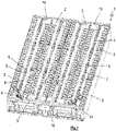
- the figure 1 shows an energy storage device 1 with a plurality of cell modules 2, which are arranged side by side in a housing 3, wherein the housing 2 can be closed with a cover, not shown.
- Each cell module 2 has five relief ports 4 arranged in a line at equal intervals in the longitudinal axis direction of each cell module 2 .
- the overpressure openings 4 are arranged below bracket-shaped brackets 5 .
- Each holder 5 has a U-shaped cross section, so that a receptacle 6 is formed which is directed upwards and serves to receive a signal generator 7 .
- the signal transmitter 7 is designed as an electrical conductor, for example as a fire alarm cable, with the signal transmitter 7 being fastened with a first end 8 to an electrically conductive element 9 and extending from there in the direction of the longitudinal axis of the first cell module 2 such that the signal transmitter 7 in the Shots 6 of each holder 5 of this cell module 2 are arranged directly above the respective overpressure opening 4 .
- the signal transmitter 7 is laid in a semicircular loop 10 and runs from there in the direction of the longitudinal axis of the second cell module 2.
- the signal transmitter 7 is also in the area of the second cell module 2 in the receptacles 6 of the brackets 5 above the overpressure openings 4 in the second cell module 2 are inserted.
- the signal transmitter 7 is again laid in a semicircular loop 10, so that the signal transmitter 7 subsequently runs in the longitudinal axis direction of the third cell module 2 and after passing through another semicircular loop 10 in the longitudinal axis direction of the fourth cell module 2 , respectively fixed in the corresponding receptacles 6 of the corresponding holders 5 above the overpressure openings 4 of the cell modules 2.
- the second end 11 of the signal generator 7 is also attached to the conductive element 9 .
- a chemical and/or thermal reaction occurs, for example in a cell module 2, as a result of which the pressure in the cell module 2 increases and the pressure in this cell module 2 reaches a level that requires an opening of at least one Overpressure opening 4 causes the signal transmitter 7 above the overpressure opening 4 to be mechanically and/or thermally loaded and separated by the load.
- the separation of the signal transmitter 7 can be detected via the conductive element 9, resulting in a signal which is transmitted to a safety device or a fire alarm system, which is not shown in detail.
- this signal which signals an emergency message, passengers sitting in a rail vehicle equipped with the energy storage device 1 can be warned and asked to leave the rail vehicle, for example.
- an optical and/or acoustic signal can be generated.
- the signal interrupts the journey of the rail vehicle at a suitable point and, for example, opens certain emergency exits that the passengers of the rail vehicle can use to exit.
Landscapes
- Chemical & Material Sciences (AREA)
- Chemical Kinetics & Catalysis (AREA)
- Electrochemistry (AREA)
- General Chemical & Material Sciences (AREA)
- Engineering & Computer Science (AREA)
- Manufacturing & Machinery (AREA)
- Materials Engineering (AREA)
- Aviation & Aerospace Engineering (AREA)
- Microelectronics & Electronic Packaging (AREA)
- Fire-Detection Mechanisms (AREA)
- Fire Alarms (AREA)
Applications Claiming Priority (1)
| Application Number | Priority Date | Filing Date | Title |
|---|---|---|---|
| DE102020132340.9A DE102020132340A1 (de) | 2020-12-04 | 2020-12-04 | Energiespeichervorrichtung, Überwachungseinheit für eine Energiespeichervorrichtung und Verfahren zur Herstellung einer Energiespeichervorrichtung |
Publications (1)
| Publication Number | Publication Date |
|---|---|
| EP4009412A1 true EP4009412A1 (fr) | 2022-06-08 |
Family
ID=78709274
Family Applications (1)
| Application Number | Title | Priority Date | Filing Date |
|---|---|---|---|
| EP21209217.5A Pending EP4009412A1 (fr) | 2020-12-04 | 2021-11-19 | Dispositif accumulateur d'énergie et unité de surveillance pour un dispositif accumulateur d'énergie |
Country Status (2)
| Country | Link |
|---|---|
| EP (1) | EP4009412A1 (fr) |
| DE (1) | DE102020132340A1 (fr) |
Cited By (1)
| Publication number | Priority date | Publication date | Assignee | Title |
|---|---|---|---|---|
| DE102023118696A1 (de) | 2023-07-14 | 2025-01-16 | Audi Aktiengesellschaft | Batterieanordnung, Kraftfahrzeug und Verfahren zum Erfassen eines Gasaustritts aus einer Batteriezelle |
Citations (5)
| Publication number | Priority date | Publication date | Assignee | Title |
|---|---|---|---|---|
| JP2005322471A (ja) | 2004-05-07 | 2005-11-17 | Toyota Motor Corp | 電池安全弁の状態を検知する検知装置、その検知装置を有する電池および集合電池 |
| DE102012001156A1 (de) | 2012-01-21 | 2013-07-25 | Daimler Ag | Energiespeichervorrichtung mit Sicherungseinrichtung |
| DE102012022126A1 (de) | 2012-11-13 | 2013-09-05 | Daimler Ag | Überwachungseinheit und Verfahren zur Überwachung einer Batteriesicherheitseinrichtung |
| US20180287126A1 (en) * | 2015-01-05 | 2018-10-04 | Johnson Controls Technology Company | Vent shield for a battery module |
| WO2020220462A1 (fr) | 2019-04-30 | 2020-11-05 | 宁德时代新能源科技股份有限公司 | Bloc-batterie |
Family Cites Families (3)
| Publication number | Priority date | Publication date | Assignee | Title |
|---|---|---|---|---|
| DE4403577A1 (de) | 1994-02-05 | 1995-08-10 | Hossein Prof Dr Ing Borsi | Sensor zur Früherkennung von unzulässigen Temperaturen und lokalen Brandherden in Transformatoren, Wicklungen, Spulen und Wandlern |
| EP1172779A3 (fr) | 2000-07-11 | 2003-02-12 | Uponor Innovation Ab | Tuyaux avec détection d'incendie intégrée |
| CN101164639B (zh) | 2006-10-19 | 2012-04-18 | 首安工业消防有限公司 | 一种带短路故障报警的不可恢复式线型感温探测器 |
-
2020
- 2020-12-04 DE DE102020132340.9A patent/DE102020132340A1/de active Pending
-
2021
- 2021-11-19 EP EP21209217.5A patent/EP4009412A1/fr active Pending
Patent Citations (5)
| Publication number | Priority date | Publication date | Assignee | Title |
|---|---|---|---|---|
| JP2005322471A (ja) | 2004-05-07 | 2005-11-17 | Toyota Motor Corp | 電池安全弁の状態を検知する検知装置、その検知装置を有する電池および集合電池 |
| DE102012001156A1 (de) | 2012-01-21 | 2013-07-25 | Daimler Ag | Energiespeichervorrichtung mit Sicherungseinrichtung |
| DE102012022126A1 (de) | 2012-11-13 | 2013-09-05 | Daimler Ag | Überwachungseinheit und Verfahren zur Überwachung einer Batteriesicherheitseinrichtung |
| US20180287126A1 (en) * | 2015-01-05 | 2018-10-04 | Johnson Controls Technology Company | Vent shield for a battery module |
| WO2020220462A1 (fr) | 2019-04-30 | 2020-11-05 | 宁德时代新能源科技股份有限公司 | Bloc-batterie |
Cited By (1)
| Publication number | Priority date | Publication date | Assignee | Title |
|---|---|---|---|---|
| DE102023118696A1 (de) | 2023-07-14 | 2025-01-16 | Audi Aktiengesellschaft | Batterieanordnung, Kraftfahrzeug und Verfahren zum Erfassen eines Gasaustritts aus einer Batteriezelle |
Also Published As
| Publication number | Publication date |
|---|---|
| DE102020132340A1 (de) | 2022-06-09 |
Similar Documents
| Publication | Publication Date | Title |
|---|---|---|
| DE102008034868B4 (de) | Batterie mit einer in einem Batteriegehäuse angeordneten Wärmeleitplatte zum Temperieren der Batterie | |
| EP3545568B1 (fr) | Système de batterie | |
| EP3392070A1 (fr) | Bloc-batterie et véhicule électrique | |
| EP3350851B1 (fr) | Module de batterie, son procédé de fabrication ainsi que batterie | |
| DE102012219784A1 (de) | Batteriemodul mit einem Gaskanal | |
| EP3785285B1 (fr) | Commutateur à haute tension, alimentation de bord à haute tension dans un véhicule automobile et procédé de fonctionnement d'un commutateur à haute tension | |
| DE102011103118A1 (de) | Vorrichtung und Verfahren zum automatischen Entladen einer Batterie eines Fahrzeuges | |
| DE102008059956A1 (de) | Batterie, insbesondere Fahrzeugbatterie | |
| WO2022073684A1 (fr) | Accumulateur d'énergie électrique | |
| DE102014006807A1 (de) | Batteriesystem mit Sensorvorrichtung | |
| DE102013203108A1 (de) | Schutz für Abblasventile von Akkumulatorzellen | |
| DE102008047502A1 (de) | Vorrichtung zur Energieverteilung in einem Fahrzeug | |
| DE102020117546A1 (de) | Schutzvorrichtung für Batteriezellen | |
| EP4009412A1 (fr) | Dispositif accumulateur d'énergie et unité de surveillance pour un dispositif accumulateur d'énergie | |
| WO2016015958A1 (fr) | Module de batterie | |
| DE102022201948B4 (de) | System zur Überwachung und Sicherheitserhöhung eines Batteriesystems, insbesondere eines Batteriesystems eines Kraftfahrzeuges, das als Antriebsenergiespeicher dient | |
| DE102007007986A1 (de) | Befestigung von Energiespeicherzellen in einem Gehäuse | |
| DE102009035467A1 (de) | Batterieeinzelzelle mit einem Gehäuse | |
| DE102014208543A1 (de) | Batteriezelleinrichtung mit einer Batteriezelle und einer Überwachungselektronik zum Überwachen der Batteriezelle und entsprechendes Verfahren zum Betreiben und Überwachen einer Batteriezelle | |
| WO2016071100A1 (fr) | Batterie à sécurité améliorée | |
| DE102020004558A1 (de) | Vorrichtung zur Erfassung eines Druckabfalls | |
| EP3159952B1 (fr) | Dispositif de securite pour systemes de batterie | |
| AT525598B1 (de) | Schutzvorrichtung für Batteriezellen | |
| DE102021123979A1 (de) | Batteriegehäuseanordnung, Batterie und Verfahren zum Detektieren eines Defekts einer Batterie | |
| DE102021208345A1 (de) | Batteriesystem für ein Fahrzeug mit Entgasungseinrichtung sowie Verfahren zum Entgasen eines Batteriesystems |
Legal Events
| Date | Code | Title | Description |
|---|---|---|---|
| PUAI | Public reference made under article 153(3) epc to a published international application that has entered the european phase |
Free format text: ORIGINAL CODE: 0009012 |
|
| STAA | Information on the status of an ep patent application or granted ep patent |
Free format text: STATUS: THE APPLICATION HAS BEEN PUBLISHED |
|
| AK | Designated contracting states |
Kind code of ref document: A1 Designated state(s): AL AT BE BG CH CY CZ DE DK EE ES FI FR GB GR HR HU IE IS IT LI LT LU LV MC MK MT NL NO PL PT RO RS SE SI SK SM TR |
|
| STAA | Information on the status of an ep patent application or granted ep patent |
Free format text: STATUS: REQUEST FOR EXAMINATION WAS MADE |
|
| 17P | Request for examination filed |
Effective date: 20220721 |
|
| RBV | Designated contracting states (corrected) |
Designated state(s): AL AT BE BG CH CY CZ DE DK EE ES FI FR GB GR HR HU IE IS IT LI LT LU LV MC MK MT NL NO PL PT RO RS SE SI SK SM TR |
|
| RIN1 | Information on inventor provided before grant (corrected) |
Inventor name: TRAPP, MAGNUS Inventor name: REINHOLD, STEFAN |
|
| P01 | Opt-out of the competence of the unified patent court (upc) registered |
Effective date: 20230522 |
|
| RAP3 | Party data changed (applicant data changed or rights of an application transferred) |
Owner name: HOPPECKE RAIL SYSTEMS GMBH |
|
| RAP1 | Party data changed (applicant data changed or rights of an application transferred) |
Owner name: HOPPECKE SYSTEMTECHNIK GMBH |