EP4009423B1 - Batterie, batterieanordnung, elektrische vorrichtung sowie herstellungsverfahren und vorrichtung für eine batterie - Google Patents
Batterie, batterieanordnung, elektrische vorrichtung sowie herstellungsverfahren und vorrichtung für eine batterie Download PDFInfo
- Publication number
- EP4009423B1 EP4009423B1 EP20941517.3A EP20941517A EP4009423B1 EP 4009423 B1 EP4009423 B1 EP 4009423B1 EP 20941517 A EP20941517 A EP 20941517A EP 4009423 B1 EP4009423 B1 EP 4009423B1
- Authority
- EP
- European Patent Office
- Prior art keywords
- connector
- battery
- box
- power consumption
- groove
- Prior art date
- Legal status (The legal status is an assumption and is not a legal conclusion. Google has not performed a legal analysis and makes no representation as to the accuracy of the status listed.)
- Active
Links
Images


Classifications
-
- H—ELECTRICITY
- H01—ELECTRIC ELEMENTS
- H01M—PROCESSES OR MEANS, e.g. BATTERIES, FOR THE DIRECT CONVERSION OF CHEMICAL ENERGY INTO ELECTRICAL ENERGY
- H01M50/00—Constructional details or processes of manufacture of the non-active parts of electrochemical cells other than fuel cells, e.g. hybrid cells
- H01M50/10—Primary casings; Jackets or wrappings
- H01M50/172—Arrangements of electric connectors penetrating the casing
- H01M50/174—Arrangements of electric connectors penetrating the casing adapted for the shape of the cells
- H01M50/176—Arrangements of electric connectors penetrating the casing adapted for the shape of the cells for prismatic or rectangular cells
-
- H—ELECTRICITY
- H01—ELECTRIC ELEMENTS
- H01M—PROCESSES OR MEANS, e.g. BATTERIES, FOR THE DIRECT CONVERSION OF CHEMICAL ENERGY INTO ELECTRICAL ENERGY
- H01M50/00—Constructional details or processes of manufacture of the non-active parts of electrochemical cells other than fuel cells, e.g. hybrid cells
- H01M50/20—Mountings; Secondary casings or frames; Racks, modules or packs; Suspension devices; Shock absorbers; Transport or carrying devices; Holders
- H01M50/204—Racks, modules or packs for multiple batteries or multiple cells
-
- H—ELECTRICITY
- H01—ELECTRIC ELEMENTS
- H01M—PROCESSES OR MEANS, e.g. BATTERIES, FOR THE DIRECT CONVERSION OF CHEMICAL ENERGY INTO ELECTRICAL ENERGY
- H01M50/00—Constructional details or processes of manufacture of the non-active parts of electrochemical cells other than fuel cells, e.g. hybrid cells
- H01M50/10—Primary casings; Jackets or wrappings
- H01M50/183—Sealing members
- H01M50/186—Sealing members characterised by the disposition of the sealing members
-
- H—ELECTRICITY
- H01—ELECTRIC ELEMENTS
- H01M—PROCESSES OR MEANS, e.g. BATTERIES, FOR THE DIRECT CONVERSION OF CHEMICAL ENERGY INTO ELECTRICAL ENERGY
- H01M50/00—Constructional details or processes of manufacture of the non-active parts of electrochemical cells other than fuel cells, e.g. hybrid cells
- H01M50/20—Mountings; Secondary casings or frames; Racks, modules or packs; Suspension devices; Shock absorbers; Transport or carrying devices; Holders
- H01M50/296—Mountings; Secondary casings or frames; Racks, modules or packs; Suspension devices; Shock absorbers; Transport or carrying devices; Holders characterised by terminals of battery packs
-
- H—ELECTRICITY
- H01—ELECTRIC ELEMENTS
- H01M—PROCESSES OR MEANS, e.g. BATTERIES, FOR THE DIRECT CONVERSION OF CHEMICAL ENERGY INTO ELECTRICAL ENERGY
- H01M50/00—Constructional details or processes of manufacture of the non-active parts of electrochemical cells other than fuel cells, e.g. hybrid cells
- H01M50/50—Current conducting connections for cells or batteries
- H01M50/543—Terminals
- H01M50/564—Terminals characterised by their manufacturing process
-
- H—ELECTRICITY
- H01—ELECTRIC ELEMENTS
- H01R—ELECTRICALLY-CONDUCTIVE CONNECTIONS; STRUCTURAL ASSOCIATIONS OF A PLURALITY OF MUTUALLY-INSULATED ELECTRICAL CONNECTING ELEMENTS; COUPLING DEVICES; CURRENT COLLECTORS
- H01R13/00—Details of coupling devices of the kinds covered by groups H01R12/70 or H01R24/00 - H01R33/00
- H01R13/62—Means for facilitating engagement or disengagement of coupling parts or for holding them in engagement
- H01R13/629—Additional means for facilitating engagement or disengagement of coupling parts, e.g. aligning or guiding means, levers, gas pressure electrical locking indicators, manufacturing tolerances
- H01R13/631—Additional means for facilitating engagement or disengagement of coupling parts, e.g. aligning or guiding means, levers, gas pressure electrical locking indicators, manufacturing tolerances for engagement only
-
- H—ELECTRICITY
- H01—ELECTRIC ELEMENTS
- H01M—PROCESSES OR MEANS, e.g. BATTERIES, FOR THE DIRECT CONVERSION OF CHEMICAL ENERGY INTO ELECTRICAL ENERGY
- H01M2220/00—Batteries for particular applications
- H01M2220/20—Batteries in motive systems, e.g. vehicle, ship, plane
-
- H—ELECTRICITY
- H01—ELECTRIC ELEMENTS
- H01R—ELECTRICALLY-CONDUCTIVE CONNECTIONS; STRUCTURAL ASSOCIATIONS OF A PLURALITY OF MUTUALLY-INSULATED ELECTRICAL CONNECTING ELEMENTS; COUPLING DEVICES; CURRENT COLLECTORS
- H01R13/00—Details of coupling devices of the kinds covered by groups H01R12/70 or H01R24/00 - H01R33/00
- H01R13/46—Bases; Cases
- H01R13/52—Dustproof, splashproof, drip-proof, waterproof, or flameproof cases
- H01R13/5202—Sealing means between parts of housing or between housing part and a wall, e.g. sealing rings
-
- H—ELECTRICITY
- H01—ELECTRIC ELEMENTS
- H01R—ELECTRICALLY-CONDUCTIVE CONNECTIONS; STRUCTURAL ASSOCIATIONS OF A PLURALITY OF MUTUALLY-INSULATED ELECTRICAL CONNECTING ELEMENTS; COUPLING DEVICES; CURRENT COLLECTORS
- H01R13/00—Details of coupling devices of the kinds covered by groups H01R12/70 or H01R24/00 - H01R33/00
- H01R13/62—Means for facilitating engagement or disengagement of coupling parts or for holding them in engagement
- H01R13/629—Additional means for facilitating engagement or disengagement of coupling parts, e.g. aligning or guiding means, levers, gas pressure electrical locking indicators, manufacturing tolerances
-
- H—ELECTRICITY
- H01—ELECTRIC ELEMENTS
- H01R—ELECTRICALLY-CONDUCTIVE CONNECTIONS; STRUCTURAL ASSOCIATIONS OF A PLURALITY OF MUTUALLY-INSULATED ELECTRICAL CONNECTING ELEMENTS; COUPLING DEVICES; CURRENT COLLECTORS
- H01R13/00—Details of coupling devices of the kinds covered by groups H01R12/70 or H01R24/00 - H01R33/00
- H01R13/73—Means for mounting coupling parts to apparatus or structures, e.g. to a wall
- H01R13/74—Means for mounting coupling parts in openings of a panel
-
- H—ELECTRICITY
- H01—ELECTRIC ELEMENTS
- H01R—ELECTRICALLY-CONDUCTIVE CONNECTIONS; STRUCTURAL ASSOCIATIONS OF A PLURALITY OF MUTUALLY-INSULATED ELECTRICAL CONNECTING ELEMENTS; COUPLING DEVICES; CURRENT COLLECTORS
- H01R2201/00—Connectors or connections adapted for particular applications
- H01R2201/26—Connectors or connections adapted for particular applications for vehicles
-
- H—ELECTRICITY
- H01—ELECTRIC ELEMENTS
- H01R—ELECTRICALLY-CONDUCTIVE CONNECTIONS; STRUCTURAL ASSOCIATIONS OF A PLURALITY OF MUTUALLY-INSULATED ELECTRICAL CONNECTING ELEMENTS; COUPLING DEVICES; CURRENT COLLECTORS
- H01R24/00—Two-part coupling devices, or either of their cooperating parts, characterised by their overall structure
- H01R24/66—Two-part coupling devices, or either of their cooperating parts, characterised by their overall structure with pins, blades or analogous contacts and secured to apparatus or structure, e.g. to a wall
-
- Y—GENERAL TAGGING OF NEW TECHNOLOGICAL DEVELOPMENTS; GENERAL TAGGING OF CROSS-SECTIONAL TECHNOLOGIES SPANNING OVER SEVERAL SECTIONS OF THE IPC; TECHNICAL SUBJECTS COVERED BY FORMER USPC CROSS-REFERENCE ART COLLECTIONS [XRACs] AND DIGESTS
- Y02—TECHNOLOGIES OR APPLICATIONS FOR MITIGATION OR ADAPTATION AGAINST CLIMATE CHANGE
- Y02E—REDUCTION OF GREENHOUSE GAS [GHG] EMISSIONS, RELATED TO ENERGY GENERATION, TRANSMISSION OR DISTRIBUTION
- Y02E60/00—Enabling technologies; Technologies with a potential or indirect contribution to GHG emissions mitigation
- Y02E60/10—Energy storage using batteries
Definitions
- a battery is provided with a first connector, and a second connector butted with the first connector of the battery is mounted to a power consumption device, so that electric energy of the battery is transferred to a power consumption device body through the first connector and the second connector.
- the first connector and the second connector need to additionally occupy a certain amount of space, so that there is a large distance between the battery and the power consumption device body, which requires large space for mounting the battery in the power consumption device, and is not beneficial to a compact structure of the power consumption device.
- an embodiment of the present application provides a power consumption device 1 that uses a battery 100 as a power source.
- the battery 100 mentioned in the embodiments of the present application refers to a single physical module including a plurality of battery cells to provide a higher voltage and capacity.
- the battery mentioned in the present application may include a battery module, a battery pack, or the like.
- the battery generally includes a box for packaging one or more battery cells. The box can avoid liquid or other foreign matters affecting charge or discharge of the battery cell.
- the technical solutions described in the embodiments of the present application are all applicable to various apparatuses using batteries, such as mobile phones, portable devices, notebook computers, electromobiles, electric toys, electric tools, electric vehicles, ships and spacecraft.
- the spacecraft includes airplanes, rockets, space shuttles, spaceships, and the like.
- the battery 100 may be used as an operation power source of the vehicle for a circuit system of the vehicle, for example, for a working power demand of the vehicle during startup, navigation and running.
- the battery 100 may be used not only as an operation power source of the vehicle, but also as a driving power source of the vehicle, replacing or partially replacing fuel or natural gas to provide driving power for the vehicle.
- the power consumption device 1 includes the power consumption device body and the battery 100, the power consumption device body is a vehicle body, and the battery 100 is mounted to the power consumption device body.
- the battery 100 includes a box 110, a plurality of battery cells 120 and a first connector 130, the plurality of battery cells 120 is disposed in the box 110, and the first connector 130 is electrically connected to the plurality of battery cells 120 to output electric energy of the battery 100.
- the power consumption device 1 may further include a support 300, the support 300 is mounted to the power consumption device body, the battery 100 is mounted to the support 300, and the battery 100 is mounted to the power consumption device body through the support 300.
- the battery 100 and the support 300 constitute a battery assembly 10.
- the battery assembly 10 further includes a second connector 500, the second connector 500 is mounted to the support 300, and the second connector 500 is configured to be butted with the battery 100.
- the electric energy of the battery 100 may be transferred to the power consumption device body through the first connector 130 and the second connector 500.
- the battery assembly 10 further includes a first conductive member 710, a second conductive member 720 and a butting terminal 730.
- One end of the first conductive member 710 and one end of the second conductive member 720 are both connected to the second connector 500.
- Another end of the first conductive member 710 and another end of the second conductive member 720 are both connected to the butting terminal 730, and the butting terminal 730 is directly or indirectly connected to the power consumption device body.
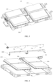
- an outer surface of the box 110 is provided with a groove 111 recessed towards the inner side of the box 110, and the first connector 130 is disposed in the groove 111.
- the second connector 500 is butted with the first connector 130, the second connector 500 is at least partially located in the groove 111.
- the provision of the groove 111 could leave space for the butting between the first connector 130 and the second connector 500, the second connector 500 on the support 300 is butted with the first connector 130 at the position of the groove 111, and the second connector 500 is partially or completely located in the groove 111, which could reduce a distance between the battery 100 and the power consumption device body, so that the battery 100 is closer to the power consumption device body, and could reduce mounting space required for mounting the batter 100 to the power consumption device body, so that the structure of the power consumption device 1 is more compact, and the arrangement of other components of the power consumption device 1 is not affected.
- the box 110 includes a lower housing 112 and an upper cover body 113, the plurality of battery cells 120 is disposed in the lower housing 112, the upper cover body 113 covers and engages with the lower housing 112, the groove 111 is formed on an outer surface of the upper cover body 113 and the outer surface of the upper cover body 113 is recessed downward, and the groove 111 penetrates one side of the upper cover body 113 in a first direction A.
- the box 110 is in a split structure, which facilitates the mounting of the plurality of battery cells 120 and other components inside the box 110, and facilitates manufacturing and molding of the box 110.
- the first connector 130 is disposed on a bottom wall of the groove 111, so that the first connector 130 is located at the deepest position of the groove 111.
- the second connector 500 could be located in the groove 111 to the maximum extent, which further reduces the mounting space required for mounting the battery 100 to the power consumption device body, so that the structure of the power consumption device 1 is more compact.
- the first connector 130 may be disposed on a side wall of the groove 111.
- the bottom wall of the groove 111 is provided with a first opening 1111, and the first connector 130 passes through the first opening 1111 to output electric energy of the plurality of battery cells 120 to an outside of the box 110 through the first connector 130.
- the first connector 130 passes through the first opening 1111 to facilitate simultaneous connection to the second connector 500 and the plurality of battery cells 120 inside the box 110, so that the first connector 130 has one portion located in the groove 111 and the other portion accommodated in the box 110, which reduces the occupation of space of the groove 111 by the first connector 130 to leave much space for the second connector 500, so that the second connector 500 could be located in the groove 111 to the maximum extent as much as possible, and further, the structure of the power consumption device 1 is more compact.
- the first connector 130 passes through the first opening 1111 from the inner side of the box 110. Moreover, the first connector 130 covers the first opening 1111 and is hermetically connected to the box 110 to close the first opening 1111. The first connector 130 covers and seals the first opening 1111, which could prevent rainwater, dust in the air and the like from entering the box 110 from the first opening 1111 and damaging the components inside the box 110.
- the outer surface of the upper cover body 113 of the box 110 is further provided with a guiding groove 114 recessed towards the inner side of the box 110, the guiding groove 114 is in communication with the groove 111, and the guiding groove 114 extends along a first direction A of the upper cover body 113 and penetrates one side of the upper cover body 113 far away from the groove 111 in the first direction A.
- a height position of the bottom wall of the groove 111 is lower than a height position of a bottom wall of the guiding groove 114, which facilitates the placement of a conductive wire connected between the second connector 500 and the power consumption device body.
- the battery 100 further includes a fixing member 150, and the fixing member 150 is configured to pass through a first through hole 1112 on the bottom wall of the groove 111 to be connected to the first connector 130.
- the fixing member 150 may be a bolt, a screw, or the like.
- the first connector 130 is fixed to the box 110 through the fixing member 150, so that the first connector 130 does not move relative to the box 110, and stable connecting relationships between the first connector 130 and the plurality of battery cells 120 and between the first connector 130 and the second connector 500 could be maintained.
- the battery 100 further includes a reinforcing plate 140, the reinforcing plate 140 is disposed on the bottom wall of the groove 111, the reinforcing plate 140 is provided with a second through hole 141 and a second opening 142 for the first connector 130 to pass through, the first opening 1111 is aligned with the second opening 142, a first connecting end 132 and a first guiding part 133 passes through the first opening 1111 and the second opening 142 in sequence.
- the second through hole 141 is aligned with the first through hole 1112, the fixing member 150 passes through the second through hole 141 and the first through hole 1112 in sequence to be connected to the first connector 130, so as to fix the reinforcing plate 140 and the first connector 130 to the box 110.
- the reinforcing plate 140 may increase the force-receiving area and ensure the hermetic seal of the entire surface.
- the provision of the reinforcing plate 140 could further improve stability of the connection between the first connector 130 and the box 110, and the reinforcing plate 140 could withstand the impact when the second connector 500 on the power consumption device 1 is butted with the first connector 130.
- the bottom wall of the groove 111 is drilled with the first opening 1111, so that the strength of the bottom wall of the groove 111 is reduced, thereby reducing bearing capacity of the bottom wall of the groove 111.
- the provision of the reinforcing plate 140 could compensate for the defect of reduction of the bearing capacity caused by drilling the first opening 1111 on the bottom wall of the groove 111.
- first through holes 1112 there are a plurality of first through holes 1112, each of the first through holes 1112 is arranged at intervals along an edge of the first opening 1111, the reinforcing plate 140 is drilled with a plurality of second through holes 141, and the second through holes 141 are arranged in one-to-one correspondence to the first through holes 1112, the first through holes 1112 are arranged in one-to-one correspondence to mounting holes on the first connector 130, and each second through hole 141 and each corresponded first through hole 1112 and each mounting hole on the first connector 130 is passing throughly provided with one fixing member 150, so that the first connector 130, the box 110 and the reinforcing plate 140 have multiple junctions to ensure uniform and stable connections and improve capacities of vibration resistance and impact resistance.
- the fixing member 150 fixes the reinforcing plate 140 and the first connector 130 to the box 110 simultaneously, which could reduce the number of fixing members 150 and the weight of the battery 100, save the costs, and reduce the difficulty of assembly of the battery 100.
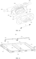
- the first connector 130 includes a base 131 and a connecting end 132, the first connecting end 132 is connected to the base 131, the base 131 has a first surface 1311, and one end of the first connecting end 132 is connected to the first surface 1311 of the base 131.
- the base 131 covers the first opening 1111 from an inner side of the box 110, the first surface 1311 of the base 131 faces the first opening 1111, and the first connecting end 132 is disposed on the first surface 1311 and passes out from the first opening 1111.
- the base 131 covers the first opening 1111 from the inner side of the box 110, which has a sealing effect on the first opening 1111. After the second connector 500 is butted with the first connector 130, the base 131 can prevent the first connector 130 from moving along a direction approaching the second connector 500, avoiding the second connector 500 pulling off the first connector 130 which may cause an electrical disconnection between the first connector 130 and the plurality of battery cells 120.
- the sealing groove 1312 may be arranged on an inner surface of the upper cover body 113, and the sealing member is disposed in the sealing groove 1312 of the upper cover body 113.
- the material of the sealing member may be nitrile rubber, silica gel, nylon, or the like.
- the first connecting end 132 is provided with a positive terminal and a negative terminal, and the first connecting end 132 passes through a first opening 1111, so that the positive terminal and the negative terminal of the first connector 130 could be butted with the second connector 500, respectively.
- the first connector 130 is further provided with a first guiding part 133, the first guiding part 133 is connected to the base 131 of the first connector 130, and the first guiding part 133 is configured to guide the second connector 500 when the first connector 130 is butted, so as to align a position of the second connector 500 with that of the first connector 130.
- the provision of the first guiding part 133 could ensure an accurate butting between the first connector 130 and the second connector 500.
- the second connector 500 includes a substrate 510, a second connecting end 520 and a second guiding part 530, and the second connecting end 520 and the second guiding part 530 are connected to the substrate 510.
- the first guiding part 133 is configured to be mated with the second guiding part 530 when the first connector 130 is butted with the second connector 500 to guide the first connector 130, so as to align the position of the second connector 500 with that of the first connector 130.
- the first connector 130 and the second connector 500 are guided to be butted with each other by the mating of the first guiding parts 133 and the second guiding parts 530, which could improve accuracy of the butting between the first connector 130 and the second connector 500.
- the first guiding part 133 is a guiding sleeve
- the second guiding part 530 is a guiding pillar.
- the first connector 130 and the second connector 500 are guided to be butted with each other by the mating of the guiding sleeve and the guiding pillar, which is simple in implementation and high in reliability.
- There are two first guiding parts 133 the two guiding parts 133 are located on two sides of the first connecting end 132 along a first direction A, respectively.
- There are two second guiding parts 530, and the second guiding parts 530 are arranged in one-to-one correspondence to the first guiding parts 133.
- the first guide part 133 may also be guiding pillar, and the second guide part 530 may also be guiding sleeve.
- the second connector 500 is floatingly mounted to the support 300.
- the substrate 510 and the support 300 are connected through an elastic member (not shown), and the extension, compression or torsion of the elastic member allows the second connector 500 to have a certain floating range relative to the support 300, which avoids the case that the second connector 500 and the battery 100 cannot be accurately butted in place caused by manufacturing or mounting errors during the butting process between the second connector 500 and the battery 100.
- the floating mounting of the second connector 500 to the support 300 may also enable the first guiding parts 133 and the second guiding parts 530 to be mated in a case when the first connector 130 and the second connector 500 have a certain mounting or manufacturing error, realizing an accurate butting between the first connector 130 and the second connector 500.
- the second connector 500 further includes a first wire 540 and a second wire 550
- the second connecting end 520 includes a first terminal 521 and a second terminal 522 with opposite polarities
- one end of the first wire 540 is connected to the first terminal 521
- one end of the second wire 550 is connected to the second terminal 552
- the first wire 540 and the second wire 550 extend from two opposite sides of the substrate 510 along the first direction A, respectively.
- the first wire 540 and the second wire 550 extend from two sides of the substrate 510 along a first direction A, respectively, so that the second connector 500 has a smaller size in a second direction B.
- first conductive member 710 and the first wire 540 may be an integral structure
- second conductive member 720 and the second wire 550 may be an integral structure
- the direction of the position at which the battery 100 is butted with the second connector 500 is different according to a different orientation of the second connector 500.
- the support 300 is connected to the bottom of the vehicle body, and the second connecting end 520 is disposed to face the battery 100 along a direction of gravity, so that the battery 100 may be butted with the second connector 500 along a direction opposite to the direction of gravity to realize an electrical connection between the battery 100 and the second connector 500.
- a damage to the first connector 130 and/or the second connector 500 due to the gravity of the battery 100 may be avoided and the use of the battery 100 or the power consumption device 1 may not be affected.
- the second connecting end 520 may be arranged in other directions, and correspondingly, the first connector 130 is butted with the second connector 500 in a direction opposite to the orientation of the second connecting end 520.
- the structure of the support 300 will be described in detail below with reference to FIG. 11 .
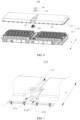
- the support 300 includes a first beam 310, a second beam 320 and a fixing frame 330, the first beam 310 and the second beam 320 are arranged opposite to each other, and accommodating space 350 for accommodating the battery 100 is formed between the first beam 310 and the second beam 320.
- the support 300 further includes a third beam 340, and the third beam 340 is connected to the first beam 310 and the second beam 320.
- the number of third beams 340 is two, and the two third beams 340 are arranged opposite to each other.
- the provision of the third beam 340 allows the structure of the support 300 to have better stability, which is beneficial to the stable mounting of the battery 100.
- the number of first beams 310 is two
- the number of second beams 320 is one
- the two first beams 310 are arranged opposite to each other
- the two first beams 310 and the one third beam 340 are connected
- the second beam 320 is located between the two first beams 310 to form two accommodating spaces 350, and each accommodating space 350 is correspondingly provided with a second connector 500.
- Two ends of the second beam 320 are connected to the two third beams 340, respectively.
- the second beam 320, the two first beams 310 and the two third beams 340 jointly form two accommodating spaces 350 of rectangular shape.
- the two accommodating spaces 350 share a second beam 320.
- the support 300 forms two accommodating spaces 350 through the second beam 320, which could accommodate two batteries 100.
- the two batteries 100 may provide a large amount of electric energy for the power consumption device 1 to ensure a normal operation of the power consumption device 1, or one of the two batteries 100 serves as a backup power source, so that the power consumption device 1 could operate continuously and stably for a long time.
Landscapes
- Chemical & Material Sciences (AREA)
- Chemical Kinetics & Catalysis (AREA)
- Electrochemistry (AREA)
- General Chemical & Material Sciences (AREA)
- Engineering & Computer Science (AREA)
- Manufacturing & Machinery (AREA)
- Battery Mounting, Suspending (AREA)
Claims (10)
- Batteriepack, das für eine Leistungsaufnahmevorrichtung (1) geeignet ist und Folgendes umfasst:einen Kasten (110);mehrere Batteriezellen (120), die im Kasten (110) angeordnet sind; undeinen ersten Verbinder (130), der mit den mehreren Batteriezellen (120) elektrisch verbunden ist, um elektrische Energie des Batteriepacks auszugeben;wobei eine Außenoberfläche des Kastens (110) mit einer Nut (111) versehen ist und der erste Verbinder (130) in der Nut (111) angeordnet ist, derart, dass ein zweiter Verbinder (500) der Leistungsaufnahmevorrichtung (1) sich mindestens teilweise in der Nut (111) befindet, wenn er am ersten Verbinder (130) anstößt;eine Bodenwand der Nut (111) mit einer ersten Öffnung (1111) versehen ist und die erste Öffnung (1111) konfiguriert ist, damit der erste Verbinder (130) sie durchläuft, um elektrische Energie der mehreren Batteriezellen (120) zu einer Außenseite des Kastens (110) durch den ersten Verbinder (130) auszugeben;der erste Verbinder (130) die erste Öffnung (1111) abdeckt und mit dem Kasten (110) hermetisch verbunden ist, um die erste Öffnung (1111) zu schließen;und der erste Verbinder (130) eine Basis (131) und ein erstes Verbindungsende (132) umfasst, wobei die Basis (131) die erste Öffnung (1111) von einer Innenseite des Kastens (110) abdeckt, eine erste Oberfläche (1311) der Basis (131) der ersten Öffnung (1111) zugewandt ist und das erste Verbindungsende (132) an der ersten Oberfläche (1311) angeordnet ist und aus der ersten Öffnung (1111) nach außen verläuft;wobei die Batterie ferner Folgendes umfasst:
ein Befestigungselement, wobei das Befestigungselement konfiguriert ist, durch ein erstes Durchgangsloch, das in einer Bodenwand der Nut vorgesehen ist, zu verlaufen, um mit dem ersten Verbinder verbunden zu sein, um den ersten Verbinder am Kasten zu befestigen. - Batteriepack nach Anspruch 1, wobei der erste Verbinder (130) an einer Bodenwand der Nut (111) angeordnet ist.
- Batteriepack nach Anspruch 1 oder 2, wobei das Batteriepack ferner Folgendes umfasst:
ein Dichtungselement, wobei das Dichtungselement zwischen der ersten Oberfläche (1311) und einer Innenoberfläche des Kastens (110) und die ersten Öffnung (1111) umgebend angeordnet ist und konfiguriert ist, eine hermetische Verbindung zwischen dem ersten Verbinder (130) und dem Kasten (110) zu realisieren. - Batteriepack nach Anspruch 3, wobei das Batteriepack ferner Folgendes umfasst:
eine Verstärkungsplatte, wobei die Verstärkungsplatte an einer Bodenwand der Nut angeordnet ist und am Kasten befestigt ist und die Verstärkungsplatte mit einer zweiten Öffnung versehen ist, die so konfiguriert ist, dass sie der erste Verbinder durchlaufen kann. - Batteriepack nach Anspruch 4, wobei die Verstärkungsplatte mit einem zweiten Durchgangsloch versehen ist und das Befestigungselement konfiguriert ist, das zweite Durchgangsloch und das erste Durchgangsloch der Reihe nach zu durchlaufen, um mit dem ersten Verbinder verbunden sein, um die Verstärkungsplatte und den ersten Verbinder am Kasten zu befestigen.
- Batterieanordnung (10), die Folgendes umfasst:einen Träger (300), der konfiguriert ist, an einem Leistungsaufnahmevorrichtungskörper montiert zu sein; unddas Batteriepack nach einem der Ansprüche 1 bis 5, wobei das Batteriepack am Träger (300) montiert ist.
- Batterieanordnung (10) nach Anspruch 6, wobei die Batterieanordnung (10) ferner Folgendes umfasst:
einen zweiten Verbinder (500), der am Träger (300) montiert ist und konfiguriert ist, an den ersten Verbinder (130) des Batteriepacks zu stoßen. - Batterieanordnung (10) nach Anspruch 7, wobei der zweite Verbinder (500) ein zweites Verbindungsende (520) umfasst und das zweite Verbindungsende (520) dem Batteriepack in Richtung der Schwerkraft zugewandt angeordnet ist, derart, dass der erste Verbinder (130) in einer Richtung entgegengesetzt zur Richtung der Schwerkraft an den zweiten Verbinder (500) stoßen kann.
- Batterieanordnung (10) nach einem der Ansprüche 6 bis 8, wobei der zweite Verbinder (500) am Träger (300) schwebend montiert ist.
- Leistungsaufnahmevorrichtung (1), die Folgendes umfasst:einen Leistungsaufnahmevorrichtungskörper;die Batterieanordnung (10) nach einem der Ansprüche 6 bis 9, wobei der Träger (300) der Batterieanordnung (10) an dem Leistungsaufnahmevorrichtungskörper montiert ist; oderdas Batteriepack nach einem der Ansprüche 1 bis 5, wobei das Batteriepack am Leistungsaufnahmevorrichtungskörper montiert ist.
Priority Applications (1)
| Application Number | Priority Date | Filing Date | Title |
|---|---|---|---|
| HUE20941517A HUE073227T2 (hu) | 2020-09-30 | 2020-09-30 | Akkumulátor, akkumulátoregység, elektromos berendezés, valamint eljárás és eszköz akkumulátor elõállításához |
Applications Claiming Priority (1)
| Application Number | Priority Date | Filing Date | Title |
|---|---|---|---|
| PCT/CN2020/119725 WO2022067800A1 (zh) | 2020-09-30 | 2020-09-30 | 电池、电池组件、用电设备、电池的制备方法及装置 |
Publications (4)
| Publication Number | Publication Date |
|---|---|
| EP4009423A1 EP4009423A1 (de) | 2022-06-08 |
| EP4009423A4 EP4009423A4 (de) | 2022-08-10 |
| EP4009423B1 true EP4009423B1 (de) | 2025-07-09 |
| EP4009423C0 EP4009423C0 (de) | 2025-07-09 |
Family
ID=80949444
Family Applications (1)
| Application Number | Title | Priority Date | Filing Date |
|---|---|---|---|
| EP20941517.3A Active EP4009423B1 (de) | 2020-09-30 | 2020-09-30 | Batterie, batterieanordnung, elektrische vorrichtung sowie herstellungsverfahren und vorrichtung für eine batterie |
Country Status (6)
| Country | Link |
|---|---|
| US (1) | US12300829B2 (de) |
| EP (1) | EP4009423B1 (de) |
| CN (1) | CN115244771A (de) |
| ES (1) | ES3042111T3 (de) |
| HU (1) | HUE073227T2 (de) |
| WO (1) | WO2022067800A1 (de) |
Families Citing this family (10)
| Publication number | Priority date | Publication date | Assignee | Title |
|---|---|---|---|---|
| US12567642B2 (en) | 2022-03-23 | 2026-03-03 | Ford Global Technologies, Llc | Shim systems for traction battery packs |
| US12479327B2 (en) | 2022-03-23 | 2025-11-25 | Ford Global Technologies, Llc | Traction battery pack cell stack removal method and battery pack assembly |
| US12506215B2 (en) | 2022-03-23 | 2025-12-23 | Ford Global Technologies, Llc | Enclosure cover attachment configurations for traction battery packs with cell-to-pack battery systems |
| US12275298B2 (en) | 2022-03-23 | 2025-04-15 | Ford Global Technologies, Llc | Traction battery packs with cell-to-pack battery systems housed within irregularly shaped enclosures |
| US12525637B2 (en) | 2022-03-23 | 2026-01-13 | Ford Global Technologies, Llc | Traction battery pack assembling method |
| US12230826B2 (en) | 2022-03-23 | 2025-02-18 | Ford Global Technologies, Llc | Methods for assembling traction battery packs |
| US12424695B2 (en) | 2022-03-23 | 2025-09-23 | Ford Global Technologies, Llc | Retention assemblies for traction battery packs with cell-to-pack battery systems |
| US12603373B2 (en) | 2022-03-23 | 2026-04-14 | Ford Global Technologies, Llc | Traction battery pack assembling method |
| US12374750B2 (en) | 2022-03-23 | 2025-07-29 | Ford Global Technologies, Llc | Traction battery pack assembling method |
| KR20240059384A (ko) * | 2022-10-27 | 2024-05-07 | 에스케이온 주식회사 | 커넥터 위치 정렬 어셈블리 및 이를 포함하는 배터리 모듈 |
Family Cites Families (10)
| Publication number | Priority date | Publication date | Assignee | Title |
|---|---|---|---|---|
| EP3300181A1 (de) | 2001-07-25 | 2018-03-28 | Sony Corporation | Strukturen von endgeräten und zu ladende komponente |
| KR102058690B1 (ko) * | 2015-12-18 | 2019-12-23 | 주식회사 엘지화학 | 배터리 모듈, 이러한 배터리 모듈을 포함하는 배터리 팩 및 이러한 배터리 팩을 포함하는 자동차 |
| KR102065096B1 (ko) * | 2016-02-12 | 2020-01-10 | 주식회사 엘지화학 | 배터리 팩 |
| CN105957991B (zh) * | 2016-07-12 | 2018-12-04 | 宁德时代新能源科技股份有限公司 | 一种电池模组 |
| WO2018133871A1 (zh) * | 2017-01-23 | 2018-07-26 | 上海电巴新能源科技有限公司 | 弹性极柱、组合件、高压组件、电连接器和电池充电盘 |
| CN208507766U (zh) * | 2018-06-28 | 2019-02-15 | 宁德时代新能源科技股份有限公司 | 电池模组 |
| KR102635922B1 (ko) * | 2018-10-10 | 2024-02-13 | 현대자동차주식회사 | 커넥터 및 이를 포함하는 차량 배터리 결합 구조 |
| CN109888570A (zh) * | 2019-03-06 | 2019-06-14 | 铠龙东方汽车有限公司 | 一种新型快换连接器 |
| CN210911986U (zh) * | 2019-08-28 | 2020-07-03 | 纳恩博(北京)科技有限公司 | 电池组件及具有其的电动车 |
| CN110571381A (zh) * | 2019-09-06 | 2019-12-13 | 安徽超稳动力节能科技有限公司 | 电池组件 |
-
2020
- 2020-09-30 CN CN202080096563.9A patent/CN115244771A/zh active Pending
- 2020-09-30 WO PCT/CN2020/119725 patent/WO2022067800A1/zh not_active Ceased
- 2020-09-30 HU HUE20941517A patent/HUE073227T2/hu unknown
- 2020-09-30 EP EP20941517.3A patent/EP4009423B1/de active Active
- 2020-09-30 ES ES20941517T patent/ES3042111T3/es active Active
-
2021
- 2021-12-29 US US17/564,428 patent/US12300829B2/en active Active
Also Published As
| Publication number | Publication date |
|---|---|
| WO2022067800A1 (zh) | 2022-04-07 |
| EP4009423A4 (de) | 2022-08-10 |
| HUE073227T2 (hu) | 2026-01-28 |
| US20220123394A1 (en) | 2022-04-21 |
| CN115244771A (zh) | 2022-10-25 |
| EP4009423A1 (de) | 2022-06-08 |
| ES3042111T3 (en) | 2025-11-18 |
| US12300829B2 (en) | 2025-05-13 |
| EP4009423C0 (de) | 2025-07-09 |
Similar Documents
| Publication | Publication Date | Title |
|---|---|---|
| EP4009423B1 (de) | Batterie, batterieanordnung, elektrische vorrichtung sowie herstellungsverfahren und vorrichtung für eine batterie | |
| EP4044329B1 (de) | Gehäuse für batterie, batterie, stromverbrauchsvorrichtung und verfahren und einrichtung zur herstellung eines gehäuses | |
| US12300831B2 (en) | Bracket, battery assembly, electric apparatus, and preparation method and device of battery assembly | |
| CN112331976B (zh) | 箱体、电池、用电设备及箱体的组装方法 | |
| US12062801B2 (en) | Frame body, battery pack, and device | |
| US20230352786A1 (en) | Accommodating apparatus, battery, electric device, and manufacturing device and method of battery | |
| WO2023088089A1 (zh) | 电池的箱体、电池、用电装置及电池的制造设备 | |
| CN218215411U (zh) | 电池单体、电池及用电设备 | |
| JP7470136B2 (ja) | 熱交換部材及びその製造方法、並びに製造システム、電池及び電気装置 | |
| CN211929598U (zh) | 一种电池单体、电池及用电的装置 | |
| WO2023186044A1 (zh) | 连接器插座、连接器组件及用电装置 | |
| CN116157951A (zh) | 电池以及用电装置 | |
| US20260018690A1 (en) | High-voltage box, battery, and electrical device | |
| US20250183490A1 (en) | Connecting terminal, battery, and electrical device | |
| CN116666917A (zh) | 电池单体、电池及用电装置 | |
| KR20240008075A (ko) | 배터리 팩 및 그의 조립 방법 | |
| CN218939912U (zh) | 极耳支架、电池及用电装置 | |
| US20250065356A1 (en) | Glue application apparatus | |
| CN222214408U (zh) | 电池装置、用电装置及连接器 | |
| CN222690868U (zh) | 电池装置、保护器及用电设备 | |
| CN222015761U (zh) | 电池装置、连接器以及用电装置 | |
| CN223451131U (zh) | 电池装置以及用电设备 | |
| CN220253345U (zh) | 顶盖组件、电池单体、电池及用电装置 | |
| CN224217680U (zh) | 一种电池单体及电池包 | |
| CN224217558U (zh) | 电池包及用电装置 |
Legal Events
| Date | Code | Title | Description |
|---|---|---|---|
| STAA | Information on the status of an ep patent application or granted ep patent |
Free format text: STATUS: UNKNOWN |
|
| STAA | Information on the status of an ep patent application or granted ep patent |
Free format text: STATUS: THE INTERNATIONAL PUBLICATION HAS BEEN MADE |
|
| PUAI | Public reference made under article 153(3) epc to a published international application that has entered the european phase |
Free format text: ORIGINAL CODE: 0009012 |
|
| STAA | Information on the status of an ep patent application or granted ep patent |
Free format text: STATUS: REQUEST FOR EXAMINATION WAS MADE |
|
| 17P | Request for examination filed |
Effective date: 20211227 |
|
| AK | Designated contracting states |
Kind code of ref document: A1 Designated state(s): AL AT BE BG CH CY CZ DE DK EE ES FI FR GB GR HR HU IE IS IT LI LT LU LV MC MK MT NL NO PL PT RO RS SE SI SK SM TR |
|
| REG | Reference to a national code |
Ref country code: DE Ipc: H01M0050204000 Ref country code: DE Ref legal event code: R079 Ref document number: 602020054422 Country of ref document: DE Free format text: PREVIOUS MAIN CLASS: H01M0050172000 Ipc: H01M0050204000 |
|
| A4 | Supplementary search report drawn up and despatched |
Effective date: 20220708 |
|
| RIC1 | Information provided on ipc code assigned before grant |
Ipc: H01M 50/564 20210101ALI20220704BHEP Ipc: H01M 50/296 20210101ALI20220704BHEP Ipc: H01M 50/204 20210101AFI20220704BHEP |
|
| STAA | Information on the status of an ep patent application or granted ep patent |
Free format text: STATUS: EXAMINATION IS IN PROGRESS |
|
| 17Q | First examination report despatched |
Effective date: 20221222 |
|
| DAV | Request for validation of the european patent (deleted) | ||
| DAX | Request for extension of the european patent (deleted) | ||
| RAP1 | Party data changed (applicant data changed or rights of an application transferred) |
Owner name: CONTEMPORARY AMPEREX TECHNOLOGY(HONG KONG) LIMITED |
|
| GRAP | Despatch of communication of intention to grant a patent |
Free format text: ORIGINAL CODE: EPIDOSNIGR1 |
|
| STAA | Information on the status of an ep patent application or granted ep patent |
Free format text: STATUS: GRANT OF PATENT IS INTENDED |
|
| INTG | Intention to grant announced |
Effective date: 20250425 |
|
| GRAS | Grant fee paid |
Free format text: ORIGINAL CODE: EPIDOSNIGR3 |
|
| GRAA | (expected) grant |
Free format text: ORIGINAL CODE: 0009210 |
|
| STAA | Information on the status of an ep patent application or granted ep patent |
Free format text: STATUS: THE PATENT HAS BEEN GRANTED |
|
| AK | Designated contracting states |
Kind code of ref document: B1 Designated state(s): AL AT BE BG CH CY CZ DE DK EE ES FI FR GB GR HR HU IE IS IT LI LT LU LV MC MK MT NL NO PL PT RO RS SE SI SK SM TR |
|
| REG | Reference to a national code |
Ref country code: GB Ref legal event code: FG4D |
|
| REG | Reference to a national code |
Ref country code: CH Ref legal event code: EP |
|
| REG | Reference to a national code |
Ref country code: IE Ref legal event code: FG4D |
|
| REG | Reference to a national code |
Ref country code: DE Ref legal event code: R096 Ref document number: 602020054422 Country of ref document: DE |
|
| U01 | Request for unitary effect filed |
Effective date: 20250808 |
|
| U07 | Unitary effect registered |
Designated state(s): AT BE BG DE DK EE FI FR IT LT LU LV MT NL PT RO SE SI Effective date: 20250820 |
|
| PGFP | Annual fee paid to national office [announced via postgrant information from national office to epo] |
Ref country code: GB Payment date: 20250916 Year of fee payment: 6 |
|
| U20 | Renewal fee for the european patent with unitary effect paid |
Year of fee payment: 6 Effective date: 20250916 |
|
| PGFP | Annual fee paid to national office [announced via postgrant information from national office to epo] |
Ref country code: HU Payment date: 20250910 Year of fee payment: 6 |
|
| REG | Reference to a national code |
Ref country code: ES Ref legal event code: FG2A Ref document number: 3042111 Country of ref document: ES Kind code of ref document: T3 Effective date: 20251118 |
|
| PG25 | Lapsed in a contracting state [announced via postgrant information from national office to epo] |
Ref country code: IS Free format text: LAPSE BECAUSE OF FAILURE TO SUBMIT A TRANSLATION OF THE DESCRIPTION OR TO PAY THE FEE WITHIN THE PRESCRIBED TIME-LIMIT Effective date: 20251109 |
|
| PG25 | Lapsed in a contracting state [announced via postgrant information from national office to epo] |
Ref country code: NO Free format text: LAPSE BECAUSE OF FAILURE TO SUBMIT A TRANSLATION OF THE DESCRIPTION OR TO PAY THE FEE WITHIN THE PRESCRIBED TIME-LIMIT Effective date: 20251009 |
|
| PG25 | Lapsed in a contracting state [announced via postgrant information from national office to epo] |
Ref country code: HR Free format text: LAPSE BECAUSE OF FAILURE TO SUBMIT A TRANSLATION OF THE DESCRIPTION OR TO PAY THE FEE WITHIN THE PRESCRIBED TIME-LIMIT Effective date: 20250709 |
|
| PG25 | Lapsed in a contracting state [announced via postgrant information from national office to epo] |
Ref country code: GR Free format text: LAPSE BECAUSE OF FAILURE TO SUBMIT A TRANSLATION OF THE DESCRIPTION OR TO PAY THE FEE WITHIN THE PRESCRIBED TIME-LIMIT Effective date: 20251010 |
|
| PG25 | Lapsed in a contracting state [announced via postgrant information from national office to epo] |
Ref country code: PL Free format text: LAPSE BECAUSE OF FAILURE TO SUBMIT A TRANSLATION OF THE DESCRIPTION OR TO PAY THE FEE WITHIN THE PRESCRIBED TIME-LIMIT Effective date: 20250709 |
|
| PG25 | Lapsed in a contracting state [announced via postgrant information from national office to epo] |
Ref country code: RS Free format text: LAPSE BECAUSE OF FAILURE TO SUBMIT A TRANSLATION OF THE DESCRIPTION OR TO PAY THE FEE WITHIN THE PRESCRIBED TIME-LIMIT Effective date: 20251009 |
|
| REG | Reference to a national code |
Ref country code: HU Ref legal event code: AG4A Ref document number: E073227 Country of ref document: HU |
|
| PGFP | Annual fee paid to national office [announced via postgrant information from national office to epo] |
Ref country code: ES Payment date: 20251002 Year of fee payment: 6 |
|
| PG25 | Lapsed in a contracting state [announced via postgrant information from national office to epo] |
Ref country code: SM Free format text: LAPSE BECAUSE OF FAILURE TO SUBMIT A TRANSLATION OF THE DESCRIPTION OR TO PAY THE FEE WITHIN THE PRESCRIBED TIME-LIMIT Effective date: 20250709 |
|
| PG25 | Lapsed in a contracting state [announced via postgrant information from national office to epo] |
Ref country code: CZ Free format text: LAPSE BECAUSE OF FAILURE TO SUBMIT A TRANSLATION OF THE DESCRIPTION OR TO PAY THE FEE WITHIN THE PRESCRIBED TIME-LIMIT Effective date: 20250709 |
|
| PG25 | Lapsed in a contracting state [announced via postgrant information from national office to epo] |
Ref country code: SK Free format text: LAPSE BECAUSE OF FAILURE TO SUBMIT A TRANSLATION OF THE DESCRIPTION OR TO PAY THE FEE WITHIN THE PRESCRIBED TIME-LIMIT Effective date: 20250709 |