EP4009434A1 - Batterie, stromverbrauchsvorrichtung und verfahren und vorrichtung zur herstellung einer batterie - Google Patents
Batterie, stromverbrauchsvorrichtung und verfahren und vorrichtung zur herstellung einer batterie Download PDFInfo
- Publication number
- EP4009434A1 EP4009434A1 EP20827955.4A EP20827955A EP4009434A1 EP 4009434 A1 EP4009434 A1 EP 4009434A1 EP 20827955 A EP20827955 A EP 20827955A EP 4009434 A1 EP4009434 A1 EP 4009434A1
- Authority
- EP
- European Patent Office
- Prior art keywords
- fire
- region
- pressure relief
- relief mechanism
- battery
- Prior art date
- Legal status (The legal status is an assumption and is not a legal conclusion. Google has not performed a legal analysis and makes no representation as to the accuracy of the status listed.)
- Granted
Links
Images


Classifications
-
- H—ELECTRICITY
- H01—ELECTRIC ELEMENTS
- H01M—PROCESSES OR MEANS, e.g. BATTERIES, FOR THE DIRECT CONVERSION OF CHEMICAL ENERGY INTO ELECTRICAL ENERGY
- H01M10/00—Secondary cells; Manufacture thereof
- H01M10/42—Methods or arrangements for servicing or maintenance of secondary cells or secondary half-cells
-
- B—PERFORMING OPERATIONS; TRANSPORTING
- B60—VEHICLES IN GENERAL
- B60L—PROPULSION OF ELECTRICALLY-PROPELLED VEHICLES; SUPPLYING ELECTRIC POWER FOR AUXILIARY EQUIPMENT OF ELECTRICALLY-PROPELLED VEHICLES; ELECTRODYNAMIC BRAKE SYSTEMS FOR VEHICLES IN GENERAL; MAGNETIC SUSPENSION OR LEVITATION FOR VEHICLES; MONITORING OPERATING VARIABLES OF ELECTRICALLY-PROPELLED VEHICLES; ELECTRIC SAFETY DEVICES FOR ELECTRICALLY-PROPELLED VEHICLES
- B60L50/00—Electric propulsion with power supplied within the vehicle
- B60L50/50—Electric propulsion with power supplied within the vehicle using propulsion power supplied by batteries or fuel cells
- B60L50/60—Electric propulsion with power supplied within the vehicle using propulsion power supplied by batteries or fuel cells using power supplied by batteries
- B60L50/64—Constructional details of batteries specially adapted for electric vehicles
-
- A—HUMAN NECESSITIES
- A62—LIFE-SAVING; FIRE-FIGHTING
- A62C—FIRE-FIGHTING
- A62C3/00—Fire prevention, containment or extinguishing specially adapted for particular objects or places
- A62C3/07—Fire prevention, containment or extinguishing specially adapted for particular objects or places in vehicles, e.g. in road vehicles
-
- A—HUMAN NECESSITIES
- A62—LIFE-SAVING; FIRE-FIGHTING
- A62C—FIRE-FIGHTING
- A62C3/00—Fire prevention, containment or extinguishing specially adapted for particular objects or places
- A62C3/16—Fire prevention, containment or extinguishing specially adapted for particular objects or places in electrical installations, e.g. cableways
-
- A—HUMAN NECESSITIES
- A62—LIFE-SAVING; FIRE-FIGHTING
- A62C—FIRE-FIGHTING
- A62C35/00—Permanently-installed equipment
- A62C35/02—Permanently-installed equipment with containers for delivering the extinguishing substance
- A62C35/10—Containers destroyed or opened by flames or heat
-
- A—HUMAN NECESSITIES
- A62—LIFE-SAVING; FIRE-FIGHTING
- A62C—FIRE-FIGHTING
- A62C35/00—Permanently-installed equipment
- A62C35/58—Pipe-line systems
- A62C35/68—Details, e.g. of pipes or valve systems
-
- B—PERFORMING OPERATIONS; TRANSPORTING
- B60—VEHICLES IN GENERAL
- B60L—PROPULSION OF ELECTRICALLY-PROPELLED VEHICLES; SUPPLYING ELECTRIC POWER FOR AUXILIARY EQUIPMENT OF ELECTRICALLY-PROPELLED VEHICLES; ELECTRODYNAMIC BRAKE SYSTEMS FOR VEHICLES IN GENERAL; MAGNETIC SUSPENSION OR LEVITATION FOR VEHICLES; MONITORING OPERATING VARIABLES OF ELECTRICALLY-PROPELLED VEHICLES; ELECTRIC SAFETY DEVICES FOR ELECTRICALLY-PROPELLED VEHICLES
- B60L58/00—Methods or circuit arrangements for monitoring or controlling batteries or fuel cells, specially adapted for electric vehicles
- B60L58/10—Methods or circuit arrangements for monitoring or controlling batteries or fuel cells, specially adapted for electric vehicles for monitoring or controlling batteries
- B60L58/24—Methods or circuit arrangements for monitoring or controlling batteries or fuel cells, specially adapted for electric vehicles for monitoring or controlling batteries for controlling the temperature of batteries
- B60L58/26—Methods or circuit arrangements for monitoring or controlling batteries or fuel cells, specially adapted for electric vehicles for monitoring or controlling batteries for controlling the temperature of batteries by cooling
-
- B—PERFORMING OPERATIONS; TRANSPORTING
- B60—VEHICLES IN GENERAL
- B60L—PROPULSION OF ELECTRICALLY-PROPELLED VEHICLES; SUPPLYING ELECTRIC POWER FOR AUXILIARY EQUIPMENT OF ELECTRICALLY-PROPELLED VEHICLES; ELECTRODYNAMIC BRAKE SYSTEMS FOR VEHICLES IN GENERAL; MAGNETIC SUSPENSION OR LEVITATION FOR VEHICLES; MONITORING OPERATING VARIABLES OF ELECTRICALLY-PROPELLED VEHICLES; ELECTRIC SAFETY DEVICES FOR ELECTRICALLY-PROPELLED VEHICLES
- B60L58/00—Methods or circuit arrangements for monitoring or controlling batteries or fuel cells, specially adapted for electric vehicles
- B60L58/10—Methods or circuit arrangements for monitoring or controlling batteries or fuel cells, specially adapted for electric vehicles for monitoring or controlling batteries
- B60L58/24—Methods or circuit arrangements for monitoring or controlling batteries or fuel cells, specially adapted for electric vehicles for monitoring or controlling batteries for controlling the temperature of batteries
- B60L58/27—Methods or circuit arrangements for monitoring or controlling batteries or fuel cells, specially adapted for electric vehicles for monitoring or controlling batteries for controlling the temperature of batteries by heating
-
- H—ELECTRICITY
- H01—ELECTRIC ELEMENTS
- H01M—PROCESSES OR MEANS, e.g. BATTERIES, FOR THE DIRECT CONVERSION OF CHEMICAL ENERGY INTO ELECTRICAL ENERGY
- H01M10/00—Secondary cells; Manufacture thereof
- H01M10/60—Heating or cooling; Temperature control
- H01M10/65—Means for temperature control structurally associated with the cells
- H01M10/655—Solid structures for heat exchange or heat conduction
- H01M10/6556—Solid parts with flow channel passages or pipes for heat exchange
-
- H—ELECTRICITY
- H01—ELECTRIC ELEMENTS
- H01M—PROCESSES OR MEANS, e.g. BATTERIES, FOR THE DIRECT CONVERSION OF CHEMICAL ENERGY INTO ELECTRICAL ENERGY
- H01M10/00—Secondary cells; Manufacture thereof
- H01M10/60—Heating or cooling; Temperature control
- H01M10/65—Means for temperature control structurally associated with the cells
- H01M10/656—Means for temperature control structurally associated with the cells characterised by the type of heat-exchange fluid
- H01M10/6567—Liquids
-
- H—ELECTRICITY
- H01—ELECTRIC ELEMENTS
- H01M—PROCESSES OR MEANS, e.g. BATTERIES, FOR THE DIRECT CONVERSION OF CHEMICAL ENERGY INTO ELECTRICAL ENERGY
- H01M10/00—Secondary cells; Manufacture thereof
- H01M10/60—Heating or cooling; Temperature control
- H01M10/65—Means for temperature control structurally associated with the cells
- H01M10/658—Means for temperature control structurally associated with the cells by thermal insulation or shielding
-
- H—ELECTRICITY
- H01—ELECTRIC ELEMENTS
- H01M—PROCESSES OR MEANS, e.g. BATTERIES, FOR THE DIRECT CONVERSION OF CHEMICAL ENERGY INTO ELECTRICAL ENERGY
- H01M50/00—Constructional details or processes of manufacture of the non-active parts of electrochemical cells other than fuel cells, e.g. hybrid cells
- H01M50/30—Arrangements for facilitating escape of gases
- H01M50/317—Re-sealable arrangements
-
- H—ELECTRICITY
- H01—ELECTRIC ELEMENTS
- H01M—PROCESSES OR MEANS, e.g. BATTERIES, FOR THE DIRECT CONVERSION OF CHEMICAL ENERGY INTO ELECTRICAL ENERGY
- H01M50/00—Constructional details or processes of manufacture of the non-active parts of electrochemical cells other than fuel cells, e.g. hybrid cells
- H01M50/30—Arrangements for facilitating escape of gases
- H01M50/342—Non-re-sealable arrangements
-
- H—ELECTRICITY
- H01—ELECTRIC ELEMENTS
- H01M—PROCESSES OR MEANS, e.g. BATTERIES, FOR THE DIRECT CONVERSION OF CHEMICAL ENERGY INTO ELECTRICAL ENERGY
- H01M50/00—Constructional details or processes of manufacture of the non-active parts of electrochemical cells other than fuel cells, e.g. hybrid cells
- H01M50/30—Arrangements for facilitating escape of gases
- H01M50/375—Vent means sensitive to or responsive to temperature
-
- H—ELECTRICITY
- H01—ELECTRIC ELEMENTS
- H01M—PROCESSES OR MEANS, e.g. BATTERIES, FOR THE DIRECT CONVERSION OF CHEMICAL ENERGY INTO ELECTRICAL ENERGY
- H01M50/00—Constructional details or processes of manufacture of the non-active parts of electrochemical cells other than fuel cells, e.g. hybrid cells
- H01M50/30—Arrangements for facilitating escape of gases
- H01M50/383—Flame arresting or ignition-preventing means
-
- H—ELECTRICITY
- H01—ELECTRIC ELEMENTS
- H01M—PROCESSES OR MEANS, e.g. BATTERIES, FOR THE DIRECT CONVERSION OF CHEMICAL ENERGY INTO ELECTRICAL ENERGY
- H01M50/00—Constructional details or processes of manufacture of the non-active parts of electrochemical cells other than fuel cells, e.g. hybrid cells
- H01M50/50—Current conducting connections for cells or batteries
- H01M50/572—Means for preventing undesired use or discharge
- H01M50/584—Means for preventing undesired use or discharge for preventing incorrect connections inside or outside the batteries
-
- B—PERFORMING OPERATIONS; TRANSPORTING
- B60—VEHICLES IN GENERAL
- B60L—PROPULSION OF ELECTRICALLY-PROPELLED VEHICLES; SUPPLYING ELECTRIC POWER FOR AUXILIARY EQUIPMENT OF ELECTRICALLY-PROPELLED VEHICLES; ELECTRODYNAMIC BRAKE SYSTEMS FOR VEHICLES IN GENERAL; MAGNETIC SUSPENSION OR LEVITATION FOR VEHICLES; MONITORING OPERATING VARIABLES OF ELECTRICALLY-PROPELLED VEHICLES; ELECTRIC SAFETY DEVICES FOR ELECTRICALLY-PROPELLED VEHICLES
- B60L2240/00—Control parameters of input or output; Target parameters
- B60L2240/40—Drive Train control parameters
- B60L2240/54—Drive Train control parameters related to batteries
- B60L2240/545—Temperature
-
- H—ELECTRICITY
- H01—ELECTRIC ELEMENTS
- H01M—PROCESSES OR MEANS, e.g. BATTERIES, FOR THE DIRECT CONVERSION OF CHEMICAL ENERGY INTO ELECTRICAL ENERGY
- H01M2200/00—Safety devices for primary or secondary batteries
- H01M2200/20—Pressure-sensitive devices
-
- Y—GENERAL TAGGING OF NEW TECHNOLOGICAL DEVELOPMENTS; GENERAL TAGGING OF CROSS-SECTIONAL TECHNOLOGIES SPANNING OVER SEVERAL SECTIONS OF THE IPC; TECHNICAL SUBJECTS COVERED BY FORMER USPC CROSS-REFERENCE ART COLLECTIONS [XRACs] AND DIGESTS
- Y02—TECHNOLOGIES OR APPLICATIONS FOR MITIGATION OR ADAPTATION AGAINST CLIMATE CHANGE
- Y02E—REDUCTION OF GREENHOUSE GAS [GHG] EMISSIONS, RELATED TO ENERGY GENERATION, TRANSMISSION OR DISTRIBUTION
- Y02E60/00—Enabling technologies; Technologies with a potential or indirect contribution to GHG emissions mitigation
- Y02E60/10—Energy storage using batteries
-
- Y—GENERAL TAGGING OF NEW TECHNOLOGICAL DEVELOPMENTS; GENERAL TAGGING OF CROSS-SECTIONAL TECHNOLOGIES SPANNING OVER SEVERAL SECTIONS OF THE IPC; TECHNICAL SUBJECTS COVERED BY FORMER USPC CROSS-REFERENCE ART COLLECTIONS [XRACs] AND DIGESTS
- Y02—TECHNOLOGIES OR APPLICATIONS FOR MITIGATION OR ADAPTATION AGAINST CLIMATE CHANGE
- Y02T—CLIMATE CHANGE MITIGATION TECHNOLOGIES RELATED TO TRANSPORTATION
- Y02T10/00—Road transport of goods or passengers
- Y02T10/60—Other road transportation technologies with climate change mitigation effect
- Y02T10/70—Energy storage systems for electromobility, e.g. batteries
Definitions
- the present application relates to the field of energy storage devices, and in particular to a battery, a power consumption device, and a method and device for producing a battery.
- the present application provides a battery, a power consumption device, and a method and device for producing a battery, which could improve the safety performance of the battery.
- a battery in a first aspect, includes: a battery cell, the battery cell including a pressure relief mechanism, the pressure relief mechanism configured to be actuated when an internal pressure or temperature of the battery cell reaches a threshold, to relieve the internal pressure or temperature; a fire-fighting pipeline configured to accommodate a fire-fighting medium, the fire-fighting pipeline including a first region corresponding to the pressure relief mechanism and a second region located at a periphery of the first region, the first region being configured to be damaged when the pressure relief mechanism is actuated, such that the fire-fighting medium is discharged, and the second region being configured to remain intact when the pressure relief mechanism is actuated, such that the fire-fighting medium is capable of flowing from the second region to the first region; and a protective component disposed between the fire-fighting pipeline and the battery cell and configured to protect the second region.
- the battery of an embodiment of the present application may include one or more battery cells, the battery cell is provided with a pressure relief mechanism, and the pressure relief mechanism may be actuated when an internal temperature or pressure of the battery cell exceeds a threshold, to relieve the internal pressure or temperature;
- a fire-fighting pipeline is provided at a position corresponding to the pressure relief mechanism, and when the pressure relief mechanism is actuated, emissions discharged from the pressure relief mechanism may damage the fire-fighting pipeline, so that a fire-fighting medium accommodated in the fire-fighting pipeline flows out from a damaged position and flows to the pressure relief mechanism so as to lower a temperature of the battery cell;
- a protective component is provided between the fire-fighting pipeline and the battery cell, and the protective component may protect a second region on the fire-fighting pipeline located at a periphery of a first region corresponding to the pressure relief mechanism, so that the pressure relief mechanism only damages the first region of the fire-fighting pipeline corresponding to the pressure relief mechanism, and further, a position where the fire-fighting
- the protective component is disposed between the second region of the fire-fighting pipeline and the battery cell, and the protective component is configured to protect the second region when the pressure relief mechanism is actuated.
- the protective component may be disposed only at the second region, for example, the second region may be wrapped by the protective component, and in this way the protective component may include a plurality of separate structures, which saves an installation space.
- the protective component includes a protective zone and a weakened zone, the protective zone is configured to protect the second region of the fire-fighting pipeline when the pressure relief mechanism is actuated, the weakened zone is disposed opposite to the pressure relief mechanism, and the weakened zone is configured such that emissions from the battery cell are capable of passing through the weakened zone to damage the first region when the pressure relief mechanism is actuated.
- the protective component may be set as an integral component, and a weakened zone corresponding to the pressure relief mechanism is provided on the protective component, so that when the pressure relief mechanism is actuated, the first region may be damaged through the weakened zone and a protective zone except the weakened zone may protect the second region from being damaged.
- a first recess is provided on the protective component, the fire-fighting pipeline is disposed in the first recess, and the first recess is configured to collect the fire-fighting medium used to flow into the battery cell when the pressure relief mechanism is actuated.
- a recess on the protective component may fix the fire-fighting pipeline and collect and guide the fire-fighting medium to flow into the battery cell.
- the weakened zone is provided in a region on a bottom wall of the first recess corresponding to the first region.
- a width of the weakened zone in a first direction is greater than or equal to a width of the bottom wall of the first recess in the first direction, and the first direction is perpendicular to an axis of the fire-fighting pipeline in the first region.
- a width of the weakened zone in a first direction is greater than a diameter of the fire-fighting pipeline, and the first direction is perpendicular to an axis of the fire-fighting pipeline in the first region.
- an orthographic projection of the weakened zone on a first plane covers an orthographic projection of the pressure relief mechanism on the first plane, and the first plane is parallel to a surface of a wall where the pressure relief mechanism of the battery cell is located facing toward an interior of the battery cell.
- the emissions discharged when the pressure relief mechanism is actuated can quickly and effectively break through the corresponding first region.
- the fire-fighting pipeline is disposed on one side of the pressure relief mechanism away from an interior of the battery cell.
- the pressure relief mechanism is an axisymmetric structure, and an axis of the fire-fighting pipeline in the first region is perpendicular to and lies in a same plane as an axis of the pressure relief mechanism.
- a melting point of a material of the protective component is greater than a melting point of a material of the fire-fighting pipeline.
- a melting point of a material of the protective component is greater than or equal to 800°C.
- a material with a high melting point should be selected for the protective component.
- a material of the protective component is mica or quartz.
- the battery further includes: a bus component configured to implement electrical connection of a plurality of battery cells; and an insulating protective layer configured to cover the bus component to prevent emissions from the battery cell from short-circuiting the plurality of the battery cells when the pressure relief mechanism is actuated, and a thickness of the insulating protective layer is greater than 0.1 mm.
- a melting point of a material of the insulating protective layer is greater than or equal to 800°C.
- a material of the insulating protective layer is mica or quartz.
- the battery further includes: an insulating layer disposed between the pressure relief mechanism and the protective component. In this way, insulation between the battery cells can be implemented.
- the insulating layer is configured to wrap the bus component of the battery, and an insulating protective layer is provided in a region on a surface of the insulating layer corresponding to the bus component, where the bus component is configured to implement electrical connection of a plurality of battery cells, and the insulating protective layer is configured to cover the bus component to prevent emissions from the battery cell from short-circuiting the plurality of the battery cells when the pressure relief mechanism is actuated.
- the protective component and the insulating protective layer are an integrally formed structure.
- a second recess is provided in a region of the insulating layer corresponding to the pressure relief mechanism, and the protective component is disposed in the second recess.
- a first recess on the protective component is disposed in the second recess
- the fire-fighting pipeline is disposed in the first recess
- the first recess is configured to collect the fire-fighting medium used to flow into the battery cell when the pressure relief mechanism is actuated.
- a fixing member is provided in the second recess, and the fixing member is configured to fix the protective component and the fire-fighting pipeline.
- a melting point of a material of the insulating layer is lower than a melting point of the protective component, and the insulating layer is melted by emissions from the battery cell when the pressure relief mechanism is actuated.
- a material with a lower melting point should be selected as a material of the insulating layer, so that the insulating layer can be quickly melted by the emissions.
- a power consumption device including the battery according to the first aspect or any one of the embodiments of the first aspect.
- the power consumption device is a vehicle, a ship or a spacecraft.
- a method for producing a battery including providing a battery cell, the battery cell including a pressure relief mechanism, the pressure relief mechanism configured to be actuated when an internal pressure or temperature of the battery cell reaches a threshold, to relieve the internal pressure or temperature; providing a fire-fighting pipeline, the fire-fighting pipeline being configured to accommodate a fire-fighting medium, the fire-fighting pipeline including a first region corresponding to the pressure relief mechanism and a second region located at a periphery of the first region, the first region being configured to be damaged when the pressure relief mechanism is actuated, such that the fire-fighting medium is discharged, and the second region being configured to remain intact when the pressure relief mechanism is actuated, such that the fire-fighting medium is capable of flowing from the second region to the first region; and providing a protective component, the protective component being disposed between the fire-fighting pipeline and the battery cell, and the protective component being configured to protect the second region.
- the protective component is disposed between the second region of the fire-fighting pipeline and the battery cell, and the protective component is configured to protect the second region when the pressure relief mechanism is actuated.
- the protective component includes a protective zone and a weakened zone, the protective zone is configured to protect the second region of the fire-fighting pipeline when the pressure relief mechanism is actuated, the weakened zone is disposed opposite to the pressure relief mechanism, and the weakened zone is configured such that emissions from the battery cell are capable of passing through the weakened zone to damage the first region when the pressure relief mechanism is actuated.
- a first recess is provided on the protective component, the fire-fighting pipeline is disposed in the first recess, and the first recess is configured to collect the fire-fighting medium used to flow into the battery cell when the pressure relief mechanism is actuated.
- a device for producing a battery including a module for executing the method provided in the foregoing third aspect.
- the terms “mounting”, “connecting”, “connection” and “attaching” should be understood in a broad sense, for example, they may be a fixed connection, a detachable connection, or an integrated connection; may be a direct connection and may also be an indirect connection via an intermediate medium, or may be communication between the interiors of two elements.
- the terms “mounting”, “connecting”, “connection” and “attaching” should be understood in a broad sense, for example, they may be a fixed connection, a detachable connection, or an integrated connection; may be a direct connection and may also be an indirect connection via an intermediate medium, or may be communication between the interiors of two elements.
- a plurality of' means two or more (including two), similarly, “a plurality of groups” means two or more groups (including two groups), and “a plurality of sheets” means two or more sheets (including two sheets).
- battery cells may include lithium-ion secondary batteries, lithium-ion primary batteries, lithium-sulfur batteries, sodium/lithium-ion batteries, sodium-ion batteries or magnesium-ion batteries, etc., which is not limited by the embodiment of the present application.
- the battery cells may be cylindrical, flat, cuboid or in another shape, which is not limited by the embodiment of the present application.
- the battery cells are generally divided into three types according to the way of packaging: cylindrical battery cells, prismatic battery cells and pouch battery cells, which is not limited by the embodiment of the present application.
- the battery mentioned in the embodiment of the present application refers to a single physical module that includes one or more battery cells to provide a higher voltage and capacity.
- the battery mentioned in the present application may include a battery module or a battery pack.
- the battery generally includes a case for enclosing one or more battery cells. The case can prevent a liquid or other foreign matters from affecting the charging or discharging of the battery cell.
- the battery cell includes an electrode assembly and an electrolytic solution, and the electrode assembly is composed of a positive electrode sheet, a negative electrode sheet and an isolation film.
- the operation of the battery cell mainly relies on the movement of metal ions between the positive electrode sheet and the negative electrode sheet.
- the positive electrode sheet includes a positive electrode current collector and a positive active material layer.
- the positive active material layer is coated on a surface of the positive electrode current collector, and the current collector not coated with the positive active material layer protrudes from the current collector coated with the positive active material layer and is used as a positive electrode tab.
- the material of the positive electrode current collector may be aluminum, and the positive active material may be lithium cobalt oxides, lithium iron phosphate, ternary lithium or lithium manganate, etc.
- the negative electrode sheet includes a negative electrode current collector and a negative active material layer. The negative active material layer is coated on a surface of the negative electrode current collector, and the current collector not coated with the negative active material layer protrudes from the current collector coated with the negative active material layer and is used as a negative electrode tab.
- the material of the negative electrode current collector may be copper, and the negative active material may be carbon or silicon, etc.
- a material of the isolation film may be PP, PE, or the like.
- the electrode assembly may have a winding structure or a laminated structure, and the embodiments of the present application are not limited thereto.
- the protection measures include at least a switching element, a properly selected isolation film material and a pressure relief mechanism.
- the switching element refers to an element that can stop the charging or discharging of a battery when the temperature or resistance in a battery cell reaches a certain threshold.
- the isolation film is configured to isolate the positive electrode sheet from the negative electrode sheet and can automatically dissolve micron-sized (or even nanoscale) micropores attached to the isolation film when the temperature rises to a certain value, thus preventing metal ions from passing through the isolation film and terminating the internal reaction of the battery cell.
- the pressure relief mechanism refers to an element or component that is actuated when an internal pressure or temperature of the battery cell reaches a predetermined threshold, to relieve the internal pressure or temperature.
- the threshold design is different according to different design requirements.
- the threshold may depend on the material of one or more of the positive electrode sheet, the negative electrode sheet, the electrolytic solution and the isolation film in the battery cell.
- the pressure relief mechanism may take the form of an explosion-proof valve, an air valve, a pressure relief valve or a safety valve, etc., and may specifically adopt a pressure-sensitive or temperature-sensitive element or structure. That is, when the internal pressure or temperature of the battery cell reaches a predetermined threshold, the pressure relief mechanism performs an action or a weakened structure provided in the pressure relief mechanism is damaged, so as to form an opening or channel for relieving the internal pressure or temperature.
- the "actuation" mentioned in the present application means that the pressure relief mechanism acts or is activated to a certain state, such that the internal pressure and temperature of the battery cell can be relieved.
- the action generated by the pressure relief mechanism may include but be not limited to: at least a portion of the pressure relief mechanism being fractured, broken, torn or opened, and so on.
- the emissions from the battery cell mentioned in the present application include but are not limited to: the electrolytic solution, the dissolved or split positive and negative electrode sheets, fragments of the isolation film, high-temperature and high-pressure gases generated by reaction, flame, etc.
- the pressure relief mechanism on the battery cell has an important impact on the safety of the battery. For example, when short circuit, overcharge and other phenomena occur, it may lead to thermal runaway inside the battery cell, resulting in a sudden increase in pressure or temperature. In this case, the internal pressure and temperature can be released outward through the actuation of the pressure relief mechanism, to prevent the battery cell from exploding and catching fire.
- the main concern is to release the high pressure and high heat inside the battery cell, i.e., to discharge the emissions to the outside of the battery cell.
- the high-temperature and high-pressure emissions are discharged along a direction of the pressure relief mechanism provided in the battery cell, and more specifically, may be discharged along a direction of a region where the pressure relief mechanism is actuated.
- the strength and destructive power of such emissions may be great, or may even be enough to break through one or more structures along this direction, causing further safety problems.
- an embodiment of the present application provides a technical solution in which a fire-fighting pipeline is provided at a corresponding position of the pressure relief mechanism of the battery cell, and emissions discharged from the battery cell when the pressure relief mechanism is actuated are used to pass through and damage the fire-fighting pipeline, so that the fire-fighting medium in the fire-fighting pipeline is discharged from a damaged position of the fire-fighting pipeline, to cool and lower a temperature of the emissions discharged from the pressure relief mechanism, thereby reducing the risk resulting from the emissions and enhancing the safety of the battery.
- the fire-fighting pipeline in an embodiment of the present application is configured to accommodate a fire-fighting medium
- the fire-fighting medium here may be a fluid, and the fluid may be a liquid or gas.
- the fire-fighting pipeline may not accommodate any substance, but in the case where the pressure relief mechanism is actuated, the fire-fighting medium may be accommodated in the fire-fighting pipeline, for example, the fire-fighting medium may be controlled to enter the fire-fighting pipeline by opening and closing a valve.
- the fire-fighting medium may always be accommodated in the fire-fighting pipeline, and the fire-fighting medium may also be used for adjusting the temperature of the battery cell.
- Temperature adjustment means heating or cooling a plurality of battery cells.
- the fire-fighting pipeline is configured to accommodate a cooling fluid to lower the temperature of the plurality of battery cells.
- the fire-fighting pipeline may also be called a cooling component, a cooling system or a cooling pipeline, etc.
- the fire-fighting medium accommodated by the fire-fighting pipeline may also be called a cooling medium or a cooling fluid, and more specifically, may be called a cooling liquid or a cooling gas.
- the fire-fighting medium can flow in a circulating manner to achieve better temperature adjustment effects.
- the fire-fighting medium may be water, a mixture of water and ethylene glycol, or air, etc.
- the case of the battery in an embodiment of the present application is configured to accommodate the plurality of battery cells, the bus component and other components of the battery.
- a structure configured to fix the battery cells may also be provided in the case.
- the shape of the case may be determined according to the plurality of battery cells accommodated therein.
- the case may be a cube with six walls.
- the bus component mentioned in the present application is configured to implement the electrical connection between the plurality of battery cells, such as parallel connection, series connection or series-parallel connection.
- the bus component may implement the electrical connection between the battery cells by connecting electrode terminals of the battery cells.
- the bus component may be fixed to the electrode terminals of the battery cells by means of welding.
- the electrical connection formed by the bus component may also be called “high-voltage connection”.
- the technical solutions described in the embodiments of the present application are all applicable to various devices using batteries, such as mobile phones, portable apparatuses, notebook computers, electromobiles, electronic toys, electric tools, electric vehicles, ships and spacecrafts.
- the spacecrafts include airplanes, rockets, space shuttles, spaceships, etc.
- FIG. 1 is a schematic structural diagram of a vehicle 1 according to an embodiment of the present application.
- the vehicle 1 may be a fuel-powered vehicle, a gas-powered vehicle or a new-energy vehicle.
- the new-energy vehicle may be a battery electric vehicle, a hybrid vehicle or an extended-range vehicle, or the like.
- a motor 40, a controller 30 and a battery 10 may be provided inside the vehicle 1, and the controller 30 is configured to control the battery 10 to supply power to the motor 40.
- the battery 10 may be provided at the bottom or the head or the tail of the vehicle 1.
- the battery 10 may be configured to supply power to the vehicle 1.
- the battery 10 can be used as an operation power supply of the vehicle 1 and is used for a circuit system of the vehicle 1, for example, for a working power demand of the vehicle 1 during startup, navigation and running.
- the battery 10 may be used not only as an operating power source for the vehicle 1 but also as a driving power source for the vehicle 1, replacing or partially replacing fuel or natural gas to provide driving power for the vehicle 1.
- the battery may include a plurality of battery cells, where the plurality of battery cells may be in series connection, parallel connection or series-parallel connection.
- the series-parallel connection refers to a combination of series connection and parallel connection.
- the battery 10 may also be called a battery pack.
- the plurality of battery cells may be first connected in series, in parallel or in series and parallel to form battery modules, and then the multiple battery modules are connected in series, in parallel or in series and parallel to form a battery 10. That is, a plurality of battery cells may directly form a battery 10, or may first form battery modules, and then the battery modules form a battery 10.
- the battery 10 may include a plurality of battery cells 20.
- the battery 10 may further include a case (or a covering) with the interior thereof being a hollow structure, and the plurality of battery cells 20 are accommodated in the case.
- the case may include two portions, which are respectively referred to as a first portion 111 and a second portion 112, respectively, and the first portion 111 and the second portion 112 are fastened together.
- the shapes of the first portion 111 and the second portion 112 may be determined according to the shape of the combined plurality of battery cells 20, and the first portion 111 and the second portion 112 may each have an opening.
- first portion 111 and the second portion 112 each may be a hollow cuboid and each have only one surface with an opening, and the opening of the first portion 111 is arranged opposite to the opening of the second portion 112.
- the first portion 111 and the second portion 112 are fastened to each other to form a case with a closed chamber.
- the plurality of battery cells 20 are combined in parallel connection or series connection or series-parallel connection and are then placed in the case formed by fastening the first portion 111 to the second portion 112.
- the battery 10 may also include other structures.
- the battery 10 may also include a bus component.
- the bus component is configured to implement the electrical connection between the plurality of battery cells 20, such as parallel connection, series connection or series-parallel connection.
- the bus component may implement the electrical connection between the battery cells 20 by connecting electrode terminals of the battery cells 20.
- the bus component may be fixed to the electrode terminals of the battery cells 20 by means of welding. Electric energy of the plurality of battery cells 20 can be further led out through an electrically conductive mechanism passing through the case.
- the electrically conductive mechanism may also belong to the bus component.
- the number of the battery cells 20 may be set to any value.
- the plurality of battery cells 20 can be connected in series, in parallel or in series and parallel to implement larger capacity or power. Since there may be many battery cells 20 included in each battery 10, the battery cells 20 may be arranged in groups for convenience of installation, and each group of battery cells 20 constitutes a battery module.
- the number of the battery cells 20 included in the battery module is not limited and may be set as required.
- FIG. 3 shows an example of a battery module.
- the battery may include a plurality of battery modules, and these battery modules may be connected in series, in parallel or in series and parallel.
- FIG. 4 is a schematic structural diagram of a battery cell 20 according to an embodiment of the present application.
- the battery cell 20 includes one or more electrode assemblies 22, a housing 211 and a cover plate 212.
- the coordinate system shown in FIG. 4 is the same as that in FIG. 3 .
- the housing 211 and the cover plate 212 form a shell or a battery box 21.
- a wall of the housing 211 and the cover plate 212 are each referred to as a wall of the battery cell 20.
- the housing 211 is shaped according to the shape of one or more electrode assemblies 22 after combination.
- the housing 211 may be a hollow cuboid or cube or cylinder, and one surface of the housing 211 has an opening such that one or more electrode assemblies 22 can be placed in the housing 211.
- one plane of the housing 211 is an opening surface, i.e., the plane does not have a wall, so that the inside and outside of the housing 211 are in communication with each other.
- an end face of the housing 211 is an opening surface, i.e., the end face does not have a wall, so that the inside and outside of the housing 211 are in communication with each other.
- the cover plate 212 covers the opening and is connected to the housing 211 to form a closed cavity in which the electrode assembly 22 is placed.
- the housing 211 is filled with an electrolyte, such as an electrolytic solution.
- the battery cell 20 may further include two electrode terminals 214, and the two electrode terminals 214 may be provided on the cover plate 212.
- the cover plate 212 is generally in the shape of a flat plate, and the two electrode terminals 214 are fixed on a flat plate surface of the cover plate 212.
- the two electrode terminals 214 are a positive electrode terminal 214a and a negative electrode terminal 214b, respectively.
- Each electrode terminal 214 is correspondingly provided with a connecting member 23 also called a current collecting member, which is located between the cover plate 212 and the electrode assembly 22 and configured to electrically connect the electrode assembly 22 to the electrode terminal 214.
- each electrode assembly 22 has a first electrode tab 221a and a second electrode tab 222a.
- the first electrode tab 221a and the second electrode tab 222a have opposite polarities.
- the first electrode tab 221a is a positive electrode tab
- the second electrode tab 222a is a negative electrode tab.
- the first electrode tab 221a of one or more electrode assemblies 22 is connected to one electrode terminal via one connecting member 23, for example, a positive electrode terminal
- the second electrode tab 222a of one or more electrode assemblies 22 is connected to the other electrode terminal via the other connecting member 23 for example, a negative electrode terminal.
- the positive electrode terminal 214a is connected to the positive electrode tab via one connecting member 23, and the negative electrode terminal 214b is connected to the negative electrode tab via the other connecting member 23.
- this battery cell 20 there may be a single or a plurality of electrode assemblies 22. As shown in FIG. 4 , there are four separate electrode assemblies 22 in the battery cell 20.
- a pressure relief mechanism 213 may also be provided on the battery cell 20.
- the pressure relief mechanism is configured to be actuated when an internal pressure or temperature of the battery cell 20 reaches a threshold, to relieve the internal pressure or temperature.
- the pressure relief mechanism 213 may have various possible pressure relief structures, which is not limited by the embodiment of the present application.
- the pressure relief mechanism 213 may be a temperature-sensitive pressure relief mechanism configured to be capable of being melted when the internal temperature of the battery cell 20 provided with the pressure relief mechanism 213 reaches a threshold; and/or the pressure relief mechanism 213 may be a pressure-sensitive pressure relief mechanism configured to be capable of being fractured when an internal gas pressure of the battery cell 20 provided with the pressure relief mechanism 213 reaches a threshold.
- a fire-fighting pipeline may be provided at a corresponding position of the pressure relief mechanism 213 of the battery cell 20.
- the fire-fighting pipeline may be provided in a direction where the emissions eject, which can directly face or not directly face the pressure relief mechanism 213, so that the fire-fighting pipeline has a place where it can be in contact with the emissions and a position where it can be damaged; and meanwhile, after the fire-fighting pipeline is damaged, the fire-fighting medium can flow from the damaged position to the battery cell 20.
- the emissions discharged from the battery cell 20 when the pressure relief mechanism 213 is actuated are used to pass through and damage the fire-fighting pipeline, so that the fire-fighting medium in the fire-fighting pipeline cools and lowers the temperature of the emissions discharged from the pressure relief mechanism 213, thereby reducing the risk resulting from the emissions and enhancing the safety of the battery 10.
- a melting point of the fire-fighting pipeline is usually set low so that the fire-fighting pipeline is easy to be melted; however, the emissions of the pressure relief mechanism 213 eject in a flared shape, this leads to a large range of the fire-fighting pipeline to be melted, for example, it is much larger than a range corresponding to the pressure relief mechanism 213, and then most of the fire-fighting medium accommodated in the fire-fighting pipeline probably flows to an exterior of the battery cell 20 where thermal runaway occurs, which will cause that the temperature of the battery cell 20 where thermal runaway occurs cannot be lowered quickly. Therefore, an embodiment of the present application provides a battery, which could solve the problems mentioned above.
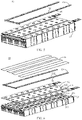
- FIG. 5 shows a schematic exploded view of a battery 10 according to an embodiment of the present application.
- the battery 10 may include a battery cell 20, and each battery 10 may include at least one battery cell 20, for example, in FIG. 5 , the case where the battery 10 includes 2 ⁇ 9 battery cells 20 is taken as an example.
- the battery cell 20 may include a pressure relief mechanism 213 (not shown in FIG. 5 ), and the pressure relief mechanism is configured to be actuated when an internal pressure or temperature of the battery cell 20 reaches a threshold, to relieve the internal pressure or temperature.
- the pressure relief mechanism 213 may be disposed at any position of the battery cell 20. It is assumed here that the battery cell 20 is a cuboid as shown in FIG. 5 , the pressure relief mechanism 213 may be disposed on any one wall of the cuboid. For example, the pressure relief mechanism 213 may be disposed on the uppermost wall of each battery cell 20 in FIG. 5 , that is, the pressure relief mechanism 213 and an electrode terminal of the battery cell 20 may be disposed on the same wall. For ease of description, in the embodiment of the present application, the case where a structure that the pressure relief mechanism 213 and the electrode terminal of the battery cell 20 are disposed on the same wall is taken as an example for description.
- the battery 10 shown in FIG. 5 may correspond to the battery 10 shown in FIG. 2 and be applicable to the related description of the battery 10 shown in FIG. 2 , for example, the battery 10 shown in FIG. 5 may also include a case and other components.
- the battery cell 20 included in the battery 10 shown in FIG. 5 may correspond to the battery cell 20 shown in FIGS. 3 and 4 , and may be applicable to the related descriptions of the battery cell 20 shown in FIGS. 3 and 4 , for example, the pressure relief mechanism 213 included in the battery cell 20 shown in FIG. 5 may correspond to the pressure relief mechanism 213 shown in FIG. 4 , which will not be repeated here for brevity.
- the battery 10 in the embodiment of the present application may further include a fire-fighting pipeline 13 configured to accommodate a fire-fighting medium.
- the fire-fighting pipeline 13 may be damaged when the pressure relief mechanism 213 is actuated, so that the fire-fighting medium accommodated therein can be discharged, and the fire-fighting medium can achieve quick cooling and temperature reduction.
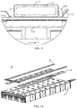
- FIG. 7 shows a schematic diagram of the fire-fighting pipeline 13 shown in FIG. 5 .
- the fire-fighting pipeline 13 may include a first region 131 and a second region 132.
- the first region 131 is disposed corresponding to the pressure relief mechanism 213, so that when the pressure relief mechanism 213 is actuated, the first region 131 can be damaged by emissions from the battery cell 20.
- the second region 132 is located at the periphery of the first region 131.
- the first region 131 is a segment of pipeline on the fire-fighting pipeline corresponding to the pressure relief mechanism 213 or a part of region toward the pressure relief mechanism 213, and the second regions 132 are two segments of pipelines adjacent to the first region 131 on two sides of the first region 131 or a part of region of the two segments of pipelines adjacent to the first region 131 toward the battery cell 20.
- the first region 131 is configured to be damaged when the pressure relief mechanism 213 is actuated, such that the fire-fighting medium is discharged, and the second region 132 is configured to remain intact when the pressure relief mechanism 213 is actuated, such that the fire-fighting medium is capable of flowing from the second region 132 to the first region 131.
- the battery 10 in the embodiment of the present application further includes a protective component 14, which is disposed between the fire-fighting pipeline 13 and the battery cell 20 and is configured to protect the second region 132, such that the second region 132 remains intact when the pressure relief mechanism 213 is actuated.
- the battery 10 of an embodiment of the present application may include one or more battery cells 20, the battery cell 20 is provided with a pressure relief mechanism 213, and the pressure relief mechanism 213 may be actuated when an internal temperature or pressure of the battery cell 20 exceeds a threshold, to relieve the internal pressure or temperature;
- a fire-fighting pipeline 13 is provided at a position corresponding to the pressure relief mechanism 213, and when the pressure relief mechanism 213 is actuated, emissions discharged from the pressure relief mechanism 213 may damage the fire-fighting pipeline 13, so that a fire-fighting medium accommodated in the fire-fighting pipeline 13 flows out and flows to the pressure relief mechanism 213 so as to lower a temperature of the battery cell 20;
- a protective component 14 is provided between the fire-fighting pipeline 13 and the battery cell 20, and the protective component 14 may protect a second region 132 on the fire-fighting pipeline 13 located at a periphery of a first region 131 corresponding to the pressure relief mechanism 13, so that the pressure relief mechanism only damages the first region 131 of the fire-fighting
- the protective component 14 in the embodiment of the present application may protect the second region 132, such that the second region 132 remains intact when the pressure relief mechanism 213 is actuated, and "intact" here may mean substantially intact.
- the pressure relief mechanism 213 When the pressure relief mechanism 213 is actuated, the discharged high-temperature and high-pressure emissions would melt the first region 131 of the fire-fighting pipeline 13, and although the second region 132 is provided with the protective component 14, a small part of the second region 132 may be damaged. Therefore, the protective component 14 can keep the second region 132 intact, which may include protecting the second region 132 from being completely damaged, or may also include keeping the second region 132 substantially intact, that is, the second region 132 is substantially protected from being damaged.
- the fire-fighting pipeline 13 in the embodiment of the present application may be set to be any shape according to practical applications.
- a cross-sectional shape of the fire-fighting pipeline 13 may be set to be any shape according to practical applications.
- the fire-fighting pipeline 13 may be set as a flat pipeline as shown in FIG. 5 , or may be set to be other shapes, such as a cylindrical pipeline.
- a shape shown in FIG. 5 is taken as an example for description.
- each battery may include one or more battery cells 20, when the battery 10 includes a large number of battery cells 20, a plurality of battery cells 20 may be arranged in an array, for example, as shown in FIG. 5 , the battery cell 10 including 2 ⁇ 9 battery cells 20 may be set.
- the fire-fighting pipeline 13 provided above the battery cell 20 may be set as a corresponding shape.
- the fire-fighting pipeline 13 may be set as a straight communication pipeline provided above the battery cell 20, which is controlled by a group of valves.
- any two adjacent rows of battery cells 20 as shown in FIG.
- the fire-fighting pipeline 13 may be set as a U-shaped communication pipeline with one bend, which is controlled by a group of valves.
- the fire-fighting pipeline 13 may also be set as an S-shaped communication pipeline with two bends, which is controlled by a group of valves.
- the fire-fighting pipeline 13 may be set as a curved communication pipeline with more bends, which may be controlled by a group of valves, or may be set as a plurality of communication pipelines respectively controlled by a plurality of groups of valves.
- the plurality of communication pipelines may include at least one of a straight pipeline, a U-shaped pipeline or an S-shaped pipeline, but the embodiment of the present application is not limited thereto.
- the case where the fire-fighting pipeline 13 is a U-shaped pipeline is taken as an example for description.
- a group of valves includes an inlet valve and/or an outlet valve, the inlet valve is configured to fill a fire-fighting medium to the fire-fighting pipeline 13, and the outlet valve is configured to discharge the fire-fighting medium outwards.
- the circulation of the fire-fighting medium in the fire-fighting pipeline 13 may be achieved by providing the inlet valve and the outlet valve at the same time, so that the fire-fighting pipeline 13 may also be used for cooling or heating when it is not damaged.
- the positions of the valves may be set according to practical applications.
- FIG. 6 shows another schematic exploded view of a battery 10 according to an embodiment of the present application.
- the wall is a cover plate of the battery cell 20, and the cover plate also includes an electrode terminal 214.
- a fire-fighting pipeline 13 is arranged at a position corresponding to the pressure relief mechanism 213, which includes according to the position of the pressure relief mechanism 213, arranging the fire-fighting pipeline 13 at a side of the pressure relief mechanism 213 away from an interior of the battery cell 20, that is, the fire-fighting pipeline 13 can be arranged above the pressure relief mechanism 213 so that the fire-fighting pipeline 13 may at least partially cover the pressure relief mechanism 213.
- the pressure relief mechanism 213 when the pressure relief mechanism 213 is actuated, the ejected emissions may damage the fire-fighting pipeline 13, so that the fire-fighting medium in the fire-fighting pipeline 13 may flow into the battery cell where thermal runaway occurs, through the pressure relief mechanism 213.
- the battery 10 may further include an insulating layer 12, the insulating layer 12 is disposed between the pressure relief mechanism 213 and the fire-fighting pipeline 13, and further, disposed between the pressure relief mechanism 213 and the protective component 14.
- the insulating layer 12 in FIG. 6 is provided on a surface of the battery cell 20 shown in FIG. 5 .
- a position corresponding to the insulating layer 12 covered above the pressure relief mechanism 213 can be quickly melted by emissions discharged from the pressure relief mechanism 213, to relieve an internal temperature and pressure of the battery cell 20. Therefore, a melting point of the material at the position on the insulating layer 12 corresponding to the pressure relief mechanism 213 is generally low.
- the insulating layer 12 in the embodiment of the present application is used for insulation between the wall where the pressure relief mechanism 213 is located and the fire-fighting pipeline 13; the insulating layer 12 may also be configured to wrap a bus component, and the bus component is configured to implement electrical connection of electrode terminals 214 of different battery cells 20, for example, a bus component 122 is located at a position on the insulating layer 12 corresponding to the electrode terminal 214 in FIG. 6 ; the insulating layer 12 may also be configured to wrap other structures disposed on the surface of the wall where the pressure relief mechanism 213 is located.
- the insulating layer 12 may also be configured to wrap a flexible printed circuit (Flexible Printed Circuit, FPC) board, and the FPC may be configured to monitor a state of each battery cell 20, for example, to monitor a temperature state or voltage state thereof, but the embodiment of the present application is not limited thereto.
- FPC Flexible Printed Circuit
- one or more battery cells 20 may be provided in the battery 10, in the case where a large number of battery cells 20 are provided, there may be a large number of bus components or FPCs and other components connecting each battery cell 20, which have a large area, and therefore these components may be integrated through the insulating layer 12 to make the assembling of the plurality of battery cells 20 more convenient.
- 2 ⁇ 9 battery cells 20 shown in FIG. 6 may be correspondingly provided with one insulating layer 12.
- the battery 10 of the embodiment of the present application further includes an insulating protective layer 15 configured to protect the bus component 122.
- the pressure relief mechanism 213 is actuated and discharges the emissions, and the emissions may melt the insulating layer 12 to expose the bus components 122, thereby causing the emissions or the fire-fighting medium in the fire-fighting pipeline 13 to flow to the bus component 122, and further causing the overlap and short circuit between the plurality of adjacent bus components 122 for connecting different battery cells. Therefore, the insulating protective layer 15 is set to protect the bus component 122 from the influence of the emissions or the fire-fighting medium in the fire-fighting pipeline 13.
- an insulating and high-temperature resistant material may be selected for the insulating protective layer 15, and the insulating protective layer 15 may be disposed on a surface of the bus component 122 or disposed at a position on a surface of the insulating layer 12 corresponding to the bus component 122, to protect the bus component 122.
- a shape and size of the insulating protective layer 15 in the embodiment of the present application may be set according to the practical applications.
- the insulating protective layer 15 may be set as a long strip shape as shown in FIG. 6 , and each of the insulating protective layers 15 may be configured to cover and protect a row of bus components 122, but the embodiment of the present application is not limited thereto.
- the protective component 14 and the insulating protective layer 15 may be independent structures, for example, the insulating protective layer 15 may be attached to an upper surface of the protective component 14 through a connecting member, and the connecting member may be glue, etc.
- the protective component 14 and the insulating protective layer 15 may also be an integrally formed structure, and the embodiment of the present application is not limited thereto.
- a thickness of the insulating protective layer 15 is greater than 0.1 mm.
- the protective component 14 in the embodiment of the present application may include various forms, and batteries including different protective components 14 will be respectively illustrated below with reference to the accompanying drawings.
- the protective component 14 may be a component only provided in the second region 132 of the fire-fighting pipeline 13. Specifically, taking FIGS. 6 and 7 as an example, the protective component 14 may be disposed between the second region 132 of the fire-fighting pipeline 13 and the battery cell 20, and configured to protect the second region 132 when the pressure relief mechanism 213 is actuated, for example, the protective component 14 may be wrapped on a surface of the second region 132.
- the protective component 14 when the protective component 14 is set as a component that wraps the second region 132, the protective component 14 and the fire-fighting pipeline 13 are still in a shape of a pipeline as a whole, and therefore the protective component 14 and the fire-fighting pipeline 13 may be installed by setting a recess.
- a second recess 121 may be provided in a region of the insulating layer 12 corresponding to the pressure relief mechanism 213, and the fire-fighting pipeline 13 wrapped by the protective component 14 is disposed in the second recess 121.
- the fire-fighting pipeline 13 is generally disposed right above the pressure relief mechanism 213, so that the first region 131 directly faces the pressure relief mechanism 213.
- the pressure relief mechanism 213 is generally axisymmetric, and an axis of the pressure relief mechanism 213 is perpendicular to and lies in a same plane as an axis of the corresponding first region 131; that is, the first region 131 directly faces the pressure relief mechanism 213.
- the second recess 121 is disposed right above the pressure relief mechanism 213, and the fire-fighting pipeline 13 is disposed in the second recess 121 to ensure that the fire-fighting pipeline 13 is disposed right above the pressure relief mechanism 213.
- a melting point of a material of the protection part 14 should be greater than a melting point of a material of the fire-fighting pipeline 13.
- a material with a higher melting point is generally selected for the protective component 14.
- a melting point of a material of the protective component 14 is greater than or equal to 800°C, and the material of the protective component 14 may be mica, quartz, etc., but the embodiment of the present application is not limited thereto.
- the first region 131 and the second region 132 included in the fire-fighting pipeline 13 in an embodiment of the present application will be described below.
- the division of the first region 131 and the second region 132 may be for the entire fire-fighting pipeline 13, or may also be for a side of the fire-fighting pipeline 13 facing the battery cell 20.
- the first region 131 in the embodiment of the present application may be a segment of pipeline in the fire-fighting pipeline 13 corresponding to the pressure relief mechanism 213, that is, the first region 131 is a segment of pipeline directly facing the pressure relief mechanism 213, or the first region 131 may also refer to a region on the surface of the fire-fighting pipeline 13 facing the battery cell 20 corresponding to the pressure relief mechanism 213, that is, the first region 131 is a region directly facing the pressure relief mechanism 213; similar to the division manner of the first region 131, the second region 132 is located at the periphery of the first region 131, that is, each second region 132 is a segment of pipeline adjacent to the first region 131, or each second region 132 is a region adjacent to the first region 131.
- the second region 132 may refer to either a segment of pipeline or a region; and when the first region 131 represents a region, the second region 132 may refer to either a segment of pipeline or a region, which is not limited thereto.
- the case where both the first region 131 and the second region 132 represent a segment of pipeline is taken as an example.
- the second region 132 located at the periphery of the first region 131 may include a plurality of division manners.
- an extending direction of the fire-fighting pipeline 13 is defined as the X direction, that is, an axis direction of the fire-fighting pipeline 13 is defined as the X direction.
- two ends of any segment of the first region 131 along the X direction is provided with second regions 132, but the sizes of the second regions 132 may be set to be different, so a segment of second region 132 (for example, as shown in FIG. 7 ) or two segments of discontinuous second regions 132 may be provided between two continuous first regions 131 along the X direction, and each second region 132 is respectively adjacent to the corresponding first region 131.
- FIG. 7 the division manner in FIG. 7 is taken as an example for description, that is, two ends of any one segment of the first region 131 along the X direction are second regions 132, and a segment of pipeline between two continuous first regions 131 corresponding to the pressure relief mechanisms 213 of any two adjacent battery cells 20 along the X direction is the second region 132; and similarly, two ends of any one segment of the second region 132 along the X direction are the first regions 131.
- lengths of the first region 131 and the second region 132 along the X direction in an embodiment of the present application may be set according to the practical applications, and the embodiment of the present application is not limited thereto.
- a length of the first region 131 along the X direction may be set according to a size of the pressure relief mechanism 213, or may be set according to a distance between the fire-fighting pipeline 13 and the pressure relief mechanism 213.
- the length of the first region 131 along the X direction may be greater than or equal to the length of the pressure relief mechanism 213 along the X direction
- the second region 132 is a pipeline of the fire-fighting pipeline 13 between two first regions 131 corresponding to two adjacent pressure relief mechanisms 213.
- FIG. 8 shows a top view of a battery 10 including a fire-fighting pipeline 13 and a battery cell 20, that is, FIG. 8 is a top view of the battery 10 shown in FIG. 6 after installation.
- a direction perpendicular to the X direction is referred to as a first direction and is denoted as the Y direction.
- a width of the fire-fighting pipeline 13 is less than or equal to a width of the second recess 121.
- a width of the insulating protective layer 15 may be set according to the practical applications, for example, the width of the insulating protective layer 15 may be set according to a width of the bus component 122 along the Y direction.
- FIG. 9 is a partial enlarged view of a cross-sectional view of the battery 10 shown in FIG. 8 along the direction A-A shown in FIG. 8 .
- the width of the pressure relief mechanism 213 is generally set to be greater than or equal to the width of the fire-fighting pipeline 13, so as to easily damage the fire-fighting pipeline 13, but the embodiment of the present application is not limited thereto.
- a fixing member 123 may be provided on the insulating layer 12.
- the fixing member 123 may be provided in the second recess 121 on the insulating layer 12, and the fixing member 123 is configured to fix the fire-fighting pipeline 13 having the protective component 14.
- the fixing member 123 may be any structure capable of fixing the fire-fighting pipeline 13, for example, as shown in FIGS. 8 and 9 , the fixing member 123 may be a buckle, but the embodiment of the present application is not limited thereto.
- the protective component 14 is a structure disposed in the second region 132 in segments is taken as an example.
- the protective component 14 may also be an integral structure disposed between the pressure relief mechanism 213 and the fire-fighting pipeline 13.
- each separate structure is only configured to protect a segment of the second region 132 in the fire-fighting pipeline 13
- the protective component 14 in an embodiment of the present application may also be one or more continuous structures, and each continuous structure may protect a plurality of segments of the second region 132 in the fire-fighting pipeline 13.
- FIG. 10 shows a schematic exploded view of a battery 10 according to a second embodiment of the present application.
- a protective component 14 may be disposed between a fire-fighting pipeline 13 and a pressure relief mechanism 213 (not shown in FIG. 10 ).
- a pressure relief mechanism 213 not shown in FIG. 10 .
- FIG. 11 shows a schematic diagram of the protective component 14 in FIG. 10 .
- the protective component 14 may include a protective zone 142 and a weakened zone 141.
- the weakened zone 141 corresponds to the first region 131
- the protective zone 142 corresponds to the second region 132.
- the protective zone 142 is a zone other than the weakened zone 141.
- the protective zone 142 covers the second region 132, for example, the protective zone 142 can cover a region of a side of the second region 132 toward the battery cell 20, and the protective zone 142 is configured to protect the second region 132 of the fire-fighting pipeline 13 when the pressure relief mechanism 213 is actuated, and the weakened zone 141 covers the first region 131 and is disposed opposite to the pressure relief mechanism 213, and the weakened zone 141 is configured such that emissions from the battery cell 20 are capable of passing through the weakened zone 141 to damage the first region 131 when the pressure relief mechanism 213 is actuated.
- the pressure relief mechanism 213 when the pressure relief mechanism 213 is actuated, it can be ensured that the first region 131 of the fire-fighting pipeline 13 is damaged and the second region 132 remains intact, and the fire-fighting medium in the second region 132 flows to the first region 131, and passes through the first region 131 and then flows out to the battery cell where thermal runaway occurs, thus achieving the effect of temperature reduction and heat dissipation.
- the weakened zone 141 in an embodiment of the present application may be a through hole or be made of a material with a lower melting point, so as to ensure that the emissions from the battery cell 20 pass through the weakened zone via the pressure relief mechanism 213 to damage the first region 131 ; on the contrary, the protective zone 142 is made of a material with a higher melting point to ensure that it is not melted by the emissions from the battery cell 20, thereby protecting the second region 132.
- a melting point of a material of the protection part 14 at the protective zone 142 should be greater than a melting point of a material of the fire-fighting pipeline 13.
- a melting point of a material of the protective component 14 is greater than or equal to 800°C, and the material of the protective component 14 may be mica, quartz, etc., but the embodiment of the present application is not limited thereto.
- the protective component 14 is also provided with a first recess 143, and the fire-fighting pipeline 13 is disposed in the first recess 143, and the weakened zone 141 is provided in a region on a bottom wall of the first recess 143 corresponding to the first region 131.
- the first recess 143 may be configured to collect the fire-fighting medium used to flow into the battery cell 20 when the pressure relief mechanism 213 is actuated.
- FIG. 12 shows another schematic exploded view of a battery 10 according to a second embodiment of the present application.
- a fire-fighting pipeline 13 may be fixed in a first recess 143 of a protective component 14, and the fire-fighting pipeline 13 and the protective component 14 may be fixed in a second recess 121 of an insulating layer 12, and an insulating protective layer 15 covers a region on a surface of the insulating layer 12 corresponding to a bus component 122.
- the insulating layer 12 in FIG. 12 may correspond to the insulating layer 12 in FIG. 6 , that is, the related description of the insulating layer 12 in FIG. 6 is applicable to the insulating layer 12 in FIG. 12 , which will not be repeated here for brevity.
- an upper surface of the battery cell 20 shown in FIG. 11 is provided with the insulating layer 12 shown in FIG. 12 .
- the insulating layer 12 is provided with the second recess 121 corresponding to the pressure relief mechanism 213, so that the protective component 14 installed with the fire-fighting pipeline 13 is disposed in the second recess 121.
- FIG. 13 shows a top view of a battery 10 according to a second embodiment of the present application. In combination with FIGS.
- the pressure relief mechanism 213 is generally axisymmetric, and an axis of the pressure relief mechanism 213 is perpendicular to and lies in a same plane as an axis of the corresponding first region 131; that is, the first region 131 directly faces the pressure relief mechanism 213.
- an orthographic projection of the weakened zone 141 on a first plane covers an orthographic projection of the pressure relief mechanism 213 on the first plane, so that the weakened zone 141 also directly faces the pressure relief mechanism 213, or it can cover the pressure relief mechanism 213, where the first plane is parallel to an upper or lower surface of the wall where the pressure relief mechanism 213 of the battery cell 20 is located, the upper surface is a surface away from an interior of the battery cell 20, and the lower surface is a surface toward the interior of the battery cell 20.
- the size of the fire-fighting pipeline 13 and the size of the protective component 14 can be set according to the practical applications.
- a width of the fire-fighting pipeline 13 is less than or equal to a width of a bottom wall of the first recess 143
- the width of the bottom wall of the first recess 143 is less than or equal to a width of a bottom wall of the second recess 121.
- a width of the insulating protective layer 15 may be set according to the practical applications, for example, the width of the insulating protective layer 15 may be set according to a direction of the bus component 122 along the Y direction.
- the width of the fire-fighting pipeline 13 may refer to a width at a position where the fire-fighting pipeline 13 is the smallest width in the Y direction.
- a width of the weakened zone 141 is generally larger than a diameter of the fire-fighting pipeline 13; however in the Y direction, the width of the weakened zone 141 may be greater than, less than or equal to a width of a bottom wall of the first recess 143. For example, as shown in FIG.
- the width of the weakened zone 141 may be greater than the width of the bottom wall of the first recess 143, so that the first region 131 may be fully exposed through the weakened zone 141, thus ensuring that the first region 131 is more easily damaged when the pressure relief mechanism 213 is actuated, but the embodiment of the present application is not limited thereto.
- FIG. 14 is a partial enlarged view of a cross-sectional view of the battery 10 shown in FIG. 13 along the direction B-B shown in FIG. 13 .
- the width of the pressure relief mechanism 213 is generally set to be greater than or equal to the width of the fire-fighting pipeline 13, but the embodiment of the present application is not limited thereto.
- a fixing member 123 may also be provided on the insulating layer 12, which will not be repeated here for brevity.
- the battery 10 of an embodiment of the present application may include one or more battery cells 20, the battery cell 20 is provided with a pressure relief mechanism 213, and the pressure relief mechanism 213 may be actuated when an internal temperature or pressure of the battery cell 20 exceeds a threshold, to relieve the internal pressure or temperature; a fire-fighting pipeline 13 is provided at a position corresponding to the pressure relief mechanism 213, and when the pressure relief mechanism 213 is actuated, emissions discharged from the pressure relief mechanism 213 may damage the fire-fighting pipeline 13, so that a fire-fighting medium accommodated in the fire-fighting pipeline 13 flows out from a damaged position and flows to the pressure relief mechanism 213 so as to lower a temperature of the battery cell 20; meanwhile, a protective component 14 is provided between the fire-fighting pipeline 13 and the battery cell 20, and the protective component 14 may protect a second region 132 on the fire-fighting pipeline 13 located at a periphery of a first region 131 corresponding to the pressure relief mechanism 13, so that the pressure relief mechanism 213 only damages the first region
- An embodiment of the present application further provides a power consumption device, which may include the battery 10 in each of the foregoing embodiments.
- the power consumption device may be a vehicle 1, a ship or a spacecraft.
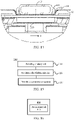
- FIG. 15 shows a schematic flowchart of a method 300 for producing a battery according to an embodiment of the present application.
- the method 300 may include: 310, providing a battery cell 20, the battery cell 20 including a pressure relief mechanism 213 configured to be actuated when an internal pressure or temperature of the battery cell 20 reaches a threshold, to relieve the internal pressure or temperature; 320, providing a fire-fighting pipeline 13, the fire-fighting pipeline 13 being configured to accommodate a fire-fighting medium, the fire-fighting pipeline 13 including a first region 131 corresponding to the pressure relief mechanism 213 and a second region 132 located at a periphery of the first region 131, the first region 131 being configured to be damaged when the pressure relief mechanism 213 is actuated, such that the fire-fighting medium is discharged, and the second region 132 being configured to remain intact when the pressure relief mechanism 213 is actuated, such that the fire-fighting medium is capable of flowing from the second region 132 to the first region 131; and
- FIG. 16 shows a schematic block diagram of a device 400 for producing a battery according to an embodiment of the present application.
- the device 400 for producing a battery may include a provision module 410.
- the provision module 410 is configured to: provide a battery cell 20, the battery cell 20 including a pressure relief mechanism 213 configured to be actuated when an internal pressure or temperature of the battery cell 20 reaches a threshold, to relieve the internal pressure or temperature; provide a fire-fighting pipeline 13, the fire-fighting pipeline 13 being configured to accommodate a fire-fighting medium, the fire-fighting pipeline 13 including a first region 131 corresponding to the pressure relief mechanism 213 and a second region 132 located at a periphery of the first region 131, the first region 131 being configured to be damaged when the pressure relief mechanism 213 is actuated, such that the fire-fighting medium is discharged, and the second region 132 being configured to remain intact when the pressure relief mechanism 213 is actuated, such that the fire-fighting medium is capable of flowing from the
Landscapes
- Engineering & Computer Science (AREA)
- Chemical & Material Sciences (AREA)
- General Chemical & Material Sciences (AREA)
- Electrochemistry (AREA)
- Chemical Kinetics & Catalysis (AREA)
- Health & Medical Sciences (AREA)
- Public Health (AREA)
- Emergency Management (AREA)
- Business, Economics & Management (AREA)
- Power Engineering (AREA)
- Sustainable Energy (AREA)
- Sustainable Development (AREA)
- Life Sciences & Earth Sciences (AREA)
- Mechanical Engineering (AREA)
- Transportation (AREA)
- Manufacturing & Machinery (AREA)
- Battery Mounting, Suspending (AREA)
- Gas Exhaust Devices For Batteries (AREA)
- Connection Of Batteries Or Terminals (AREA)
Priority Applications (1)
| Application Number | Priority Date | Filing Date | Title |
|---|---|---|---|
| HUE20827955A HUE063718T2 (hu) | 2020-10-19 | 2020-10-19 | Telep, energiafelhasználó készülék, továbbá eljárás és készülék telep gyártásához |
Applications Claiming Priority (1)
| Application Number | Priority Date | Filing Date | Title |
|---|---|---|---|
| PCT/CN2020/121992 WO2022082389A1 (zh) | 2020-10-19 | 2020-10-19 | 电池、用电设备、制备电池的方法和装置 |
Publications (3)
| Publication Number | Publication Date |
|---|---|
| EP4009434A1 true EP4009434A1 (de) | 2022-06-08 |
| EP4009434A4 EP4009434A4 (de) | 2022-06-08 |
| EP4009434B1 EP4009434B1 (de) | 2023-08-02 |
Family
ID=81186884
Family Applications (1)
| Application Number | Title | Priority Date | Filing Date |
|---|---|---|---|
| EP20827955.4A Active EP4009434B1 (de) | 2020-10-19 | 2020-10-19 | Batterie und stromverbrauchsvorrichtung |
Country Status (6)
| Country | Link |
|---|---|
| US (1) | US12036877B2 (de) |
| EP (1) | EP4009434B1 (de) |
| JP (1) | JP7350213B2 (de) |
| KR (1) | KR102646202B1 (de) |
| HU (1) | HUE063718T2 (de) |
| WO (1) | WO2022082389A1 (de) |
Families Citing this family (10)
| Publication number | Priority date | Publication date | Assignee | Title |
|---|---|---|---|---|
| KR102646202B1 (ko) | 2020-10-19 | 2024-03-12 | 지앙수 컨템포러리 엠퍼렉스 테크놀로지 리미티드 | 배터리, 전기 장치, 배터리를 제조하는 방법과 장치 |
| PL4016708T3 (pl) | 2020-10-19 | 2023-02-20 | Jiangsu Contemporary Amperex Technology Limited | Akumulator, urządzenie elektryczne i sposób oraz urządzenie do przygotowywania akumulatora |
| EP4064409A4 (de) * | 2020-10-19 | 2024-01-10 | Jiangsu Contemporary Amperex Technology Limited | Batterie, elektrisches gerät sowie verfahren und vorrichtung zum herstellen einer batterie |
| JP7580575B2 (ja) | 2020-10-19 | 2024-11-11 | ジアンス・コンテンポラリー・アンプレックス・テクノロジー・リミテッド | 電池、電気装置、電池の製造方法および装置 |
| KR102807690B1 (ko) * | 2022-05-11 | 2025-05-14 | 삼성에스디아이 주식회사 | 배터리 모듈 및 이를 포함하는 에너지 저장 시스템 |
| CN217361831U (zh) * | 2022-05-31 | 2022-09-02 | 宁德时代新能源科技股份有限公司 | 电池及用电装置 |
| CN116157958B (zh) * | 2022-06-27 | 2025-02-25 | 宁德时代新能源科技股份有限公司 | 电池以及用电装置 |
| EP4571933A1 (de) * | 2023-12-12 | 2025-06-18 | CUSTOMCELLS Holding GmbH | Batteriezellensystem, batteriezelle, kühlmittel und verfahren zum betreiben eines batteriezellensystems |
| CN120527565A (zh) * | 2024-02-22 | 2025-08-22 | 宁德时代新能源科技股份有限公司 | 一种电池和用电装置 |
| KR102910681B1 (ko) * | 2024-11-05 | 2026-01-09 | 주식회사 리모빌리티 | 열감응형 전기차 배터리 소화시스템 |
Family Cites Families (90)
| Publication number | Priority date | Publication date | Assignee | Title |
|---|---|---|---|---|
| JP2970044B2 (ja) | 1991-05-27 | 1999-11-02 | 松下電器産業株式会社 | 密閉形電池 |
| US5607787A (en) | 1993-05-04 | 1997-03-04 | Programme 3 Patent Holdings | High temperature storage battery |
| WO2000057502A1 (en) | 1999-03-22 | 2000-09-28 | Glory Win International Group Limited | A venting system for a battery |
| US20030003350A1 (en) | 2001-07-02 | 2003-01-02 | C&D Charter Holdings, Inc. | Horizontal tray insert and tray assembly for motive-power applications |
| KR100560483B1 (ko) | 2004-05-04 | 2006-03-13 | 삼성에스디아이 주식회사 | 이차 전지 |
| US7507500B2 (en) | 2004-05-17 | 2009-03-24 | Railpower Technologies Corp. | Design of a large battery pack for a hybrid locomotive |
| KR100591421B1 (ko) * | 2004-09-07 | 2006-06-21 | 삼성에스디아이 주식회사 | 형상기억 안전벤트를 갖는 리튬 이온 이차 전지 |
| KR100696685B1 (ko) | 2005-05-16 | 2007-03-20 | 삼성에스디아이 주식회사 | 이차 전지 모듈 |
| JP2008251263A (ja) | 2007-03-29 | 2008-10-16 | Sanyo Electric Co Ltd | 電源装置 |
| JP5377955B2 (ja) | 2008-12-24 | 2013-12-25 | 三洋電機株式会社 | 車両用の電源装置 |
| US9093726B2 (en) * | 2009-09-12 | 2015-07-28 | Tesla Motors, Inc. | Active thermal runaway mitigation system for use within a battery pack |
| JP2012018766A (ja) | 2010-07-06 | 2012-01-26 | Auto Network Gijutsu Kenkyusho:Kk | バスバー保持具 |
| JP2012094313A (ja) | 2010-10-26 | 2012-05-17 | Sanyo Electric Co Ltd | バッテリー装置の冷却構造 |
| KR101191660B1 (ko) | 2010-11-08 | 2012-10-17 | 에스비리모티브 주식회사 | 전지 모듈 |
| DE102011075318A1 (de) * | 2011-05-05 | 2012-11-08 | Sb Limotive Company Ltd. | Batteriegehäuse für Lithium-Ionen-Zellen |
| DE102011109249A1 (de) * | 2011-08-02 | 2013-02-07 | Daimler Ag | Hochvolt-Batterie für Fahrzeuganwendungen |
| JP6087544B2 (ja) | 2012-09-04 | 2017-03-01 | 株式会社東芝 | 組電池 |
| JP5575209B2 (ja) | 2012-11-21 | 2014-08-20 | 三菱重工業株式会社 | 電池モジュール |
| JP5761164B2 (ja) | 2012-11-30 | 2015-08-12 | トヨタ自動車株式会社 | 組電池 |
| US9614209B2 (en) | 2013-02-25 | 2017-04-04 | The Boeing Company | Aircraft including mitigation system for rechargeable batteries |
| JP5931027B2 (ja) | 2013-08-29 | 2016-06-08 | 古河電気工業株式会社 | 電池モジュール用カバー、電池モジュール |
| CN106785182B (zh) * | 2015-11-23 | 2019-06-11 | 宁德时代新能源科技股份有限公司 | 电池包 |
| JP2017139099A (ja) | 2016-02-02 | 2017-08-10 | 三菱自動車工業株式会社 | 電池モジュール |
| JP2017147128A (ja) * | 2016-02-17 | 2017-08-24 | 三菱重工業株式会社 | 電池モジュール、および、電池システム |
| JP2017152213A (ja) | 2016-02-24 | 2017-08-31 | 株式会社デンソー | 燃料電池システム |
| CN105762428B (zh) | 2016-03-03 | 2019-06-04 | 宁德时代新能源科技股份有限公司 | 电池包 |
| CN205508970U (zh) | 2016-03-18 | 2016-08-24 | 山东泰汽新能源工程研究院有限公司 | 一种新型高安全标准的锂离子电池包被动消防灭火结构 |
| CN205542977U (zh) | 2016-04-06 | 2016-08-31 | 北京迅力世达技术有限公司 | 一种电池箱应用兼有散热及灭火功能的管路结构 |
| CN205583008U (zh) | 2016-05-05 | 2016-09-14 | 宁德时代新能源科技股份有限公司 | 电池模组及其电池模块 |
| JP6627682B2 (ja) | 2016-07-29 | 2020-01-08 | 株式会社デンソー | 電池パック |
| JP6589786B2 (ja) | 2016-09-15 | 2019-10-16 | トヨタ自動車株式会社 | 電池システム |
| US20180138478A1 (en) | 2016-11-14 | 2018-05-17 | Anhui Xinen Technology Co., Ltd. | Alleviating explosion propagation in a battery module |
| CN106450575B (zh) | 2016-11-26 | 2019-03-05 | 华中科技大学 | 一种结合热管冷却和热防护的热管理系统 |
| CN106356579A (zh) | 2016-11-30 | 2017-01-25 | 重庆小康工业集团股份有限公司 | 安全型电动汽车动力电池系统 |
| EP3333932B1 (de) * | 2016-12-06 | 2019-02-13 | Samsung SDI Co., Ltd. | Batteriesystem |
| JP2018116813A (ja) | 2017-01-17 | 2018-07-26 | 株式会社東芝 | 電池モジュールおよび電池装置 |
| GB201705513D0 (en) | 2017-04-05 | 2017-05-17 | Siemens Ag | Cooling system and method |
| CN106960977A (zh) | 2017-04-28 | 2017-07-18 | 捷星新能源科技(苏州)有限公司 | 一种高安全性多功能的动力锂电池组 |
| CN206834290U (zh) | 2017-05-25 | 2018-01-02 | 惠州中科新能源研究院 | 一种冷却型方形电池模组 |
| KR102203246B1 (ko) | 2017-05-25 | 2021-01-13 | 주식회사 엘지화학 | 안전성이 향상된 배터리 모듈 |
| JP2019029245A (ja) * | 2017-08-01 | 2019-02-21 | 株式会社Gsユアサ | 蓄電装置 |
| CN207886552U (zh) | 2017-09-29 | 2018-09-21 | 郑州宇通客车股份有限公司 | 一种灭火压条及使用该压条的电池模组、电池箱、车辆 |
| CN207474504U (zh) | 2017-09-29 | 2018-06-08 | 郑州宇通客车股份有限公司 | 一种电池及使用该电池的电池模组、电池箱和车辆 |
| CN207474524U (zh) | 2017-09-29 | 2018-06-08 | 郑州宇通客车股份有限公司 | 一种车辆及其电池箱、电池模组、灭火部件、灭火容器 |
| CN107910606B (zh) | 2017-10-27 | 2020-06-19 | 天津市捷威动力工业有限公司 | 一种锂离子电池包热失控控制装置 |
| CN207909930U (zh) | 2017-11-06 | 2018-09-25 | 蔚来汽车有限公司 | 电池包存储装置 |
| CN207967074U (zh) | 2017-11-20 | 2018-10-12 | 宁德时代新能源科技股份有限公司 | 箱体 |
| CN207441811U (zh) | 2017-11-20 | 2018-06-01 | 宁德时代新能源科技股份有限公司 | 箱体及电池包 |
| CN107994175B (zh) | 2017-12-26 | 2024-07-26 | 广州雷利诺车业有限公司 | 一种电动摩托车电池箱组 |
| CN207977389U (zh) | 2018-01-29 | 2018-10-16 | 浙江美都海创锂电科技有限公司 | 一种安全防爆方形电池模块 |
| JP2019149291A (ja) | 2018-02-27 | 2019-09-05 | 株式会社Gsユアサ | 蓄電装置の製造方法及び蓄電装置 |
| JP7207814B2 (ja) | 2018-03-30 | 2023-01-18 | 三洋電機株式会社 | 電源装置と電源装置を備える電動車両 |
| CN108922998A (zh) | 2018-06-22 | 2018-11-30 | 安徽省力霸动力锂电池科技有限公司 | 一种锂电池的防爆阻燃结构 |
| CN208478517U (zh) | 2018-06-28 | 2019-02-05 | 浙江衡远新能源科技有限公司 | 一种动力电池模组的液冷结构 |
| CN110875443B (zh) | 2018-08-31 | 2021-06-08 | 宁德时代新能源科技股份有限公司 | 防护组件、封盖以及箱体 |
| KR102312415B1 (ko) | 2018-09-13 | 2021-10-12 | 주식회사 엘지에너지솔루션 | 배터리 모듈, 이러한 배터리 모듈을 포함하는 배터리 팩 및 이러한 배터리 팩을 포함하는 자동차 |
| CN109244349A (zh) | 2018-10-15 | 2019-01-18 | 王玉彪 | 一种锂离子动力电池及其操作方法 |
| CN209249563U (zh) | 2018-12-21 | 2019-08-13 | 江苏时代新能源科技有限公司 | 一种电极连接片及电池模组 |
| CN209344171U (zh) | 2018-12-27 | 2019-09-03 | 北京长城华冠汽车技术开发有限公司 | 一种液冷动力电池箱 |
| CN209662489U (zh) * | 2018-12-28 | 2019-11-22 | 宁德时代新能源科技股份有限公司 | 一种电池包的喷淋管路组件、电池包 |
| CN209071461U (zh) | 2018-12-28 | 2019-07-05 | 宁德时代新能源科技股份有限公司 | 热管理装置及电池包 |
| CN209490404U (zh) | 2018-12-28 | 2019-10-15 | 宁德时代新能源科技股份有限公司 | 一种电池包的消防流体储存装置 |
| CN209104233U (zh) * | 2018-12-28 | 2019-07-12 | 宁德时代新能源科技股份有限公司 | 一种电池包的喷淋管路组件及电池包 |
| CN111097115B (zh) | 2018-12-28 | 2021-08-20 | 宁德时代新能源科技股份有限公司 | 一种电池包的喷淋系统及电池包 |
| CN111106276B (zh) | 2018-12-28 | 2021-02-02 | 宁德时代新能源科技股份有限公司 | 一种电池包的喷淋系统、电池包 |
| KR102425695B1 (ko) | 2019-01-31 | 2022-07-28 | 삼성에스디아이 주식회사 | 전지 팩 |
| CN209401662U (zh) | 2019-03-28 | 2019-09-17 | 宁德时代新能源科技股份有限公司 | 电池包 |
| KR102742476B1 (ko) | 2019-04-01 | 2024-12-12 | 스페어 파워 시스템즈, 인크. | 배터리 시스템에 대한 열 이벤트 전파를 완화하기 위한 장치 |
| CN209592146U (zh) | 2019-04-19 | 2019-11-05 | 宁德时代新能源科技股份有限公司 | 电池模组 |
| CN208955153U (zh) | 2019-04-30 | 2019-06-07 | 中国电力科学研究院有限公司 | 具有散热与消防功能的储能电池簇 |
| CN110212265A (zh) | 2019-06-05 | 2019-09-06 | 武汉科技大学 | 一种直流快充液冷电池系统及其热管理方法 |
| CN110148694B (zh) | 2019-06-19 | 2024-08-27 | 珠海格力电器股份有限公司 | 电池模组和电池包 |
| CN209804782U (zh) | 2019-06-19 | 2019-12-17 | 珠海格力电器股份有限公司 | 电池模组和电池包 |
| CN210668459U (zh) | 2019-08-20 | 2020-06-02 | 深圳安凯利电池有限公司 | 一种锂电池的防爆阻燃结构 |
| CN210403875U (zh) | 2019-08-29 | 2020-04-24 | 惠州比亚迪实业有限公司 | 电池模组、动力电池包和车辆 |
| CN110459719B (zh) | 2019-08-29 | 2024-11-12 | 清华大学 | 电池包烟气流道系统及电池包 |
| US11735788B2 (en) | 2019-09-05 | 2023-08-22 | Samsung Sdi Co., Ltd. | Energy storage module including insulation spacers and an extinguisher sheet |
| CN210535738U (zh) | 2019-10-31 | 2020-05-15 | 上海蔚来汽车有限公司 | 电池模组的隔热组件 |
| CN210723159U (zh) | 2019-11-13 | 2020-06-09 | 苏州宇量电池有限公司 | 一种灭火动力电池模组及电池包 |
| CN110868645A (zh) | 2019-11-22 | 2020-03-06 | 安徽飞凯电子技术有限公司 | 一种防潮通信机柜 |
| CN211088371U (zh) | 2020-01-18 | 2020-07-24 | 赵波 | 一种汽车电池散热装置 |
| CN211700415U (zh) | 2020-03-25 | 2020-10-16 | 珠海冠宇动力电池有限公司 | 汇流板、汇流板定位结构、电池模组及汇流板组件 |
| CN111584792B (zh) | 2020-04-21 | 2022-11-29 | 重庆金康动力新能源有限公司 | 一种电池模组 |
| CN111509163A (zh) | 2020-05-25 | 2020-08-07 | 重庆金康动力新能源有限公司 | 具有灭火功能的电池包 |
| CN111725454B (zh) | 2020-06-12 | 2022-11-22 | 上汽通用汽车有限公司 | 电池模组及电池包总成 |
| EP3940860A1 (de) | 2020-07-16 | 2022-01-19 | ABB Schweiz AG | Batteriemodul |
| KR102646202B1 (ko) | 2020-10-19 | 2024-03-12 | 지앙수 컨템포러리 엠퍼렉스 테크놀로지 리미티드 | 배터리, 전기 장치, 배터리를 제조하는 방법과 장치 |
| JP7580575B2 (ja) | 2020-10-19 | 2024-11-11 | ジアンス・コンテンポラリー・アンプレックス・テクノロジー・リミテッド | 電池、電気装置、電池の製造方法および装置 |
| PL4016708T3 (pl) | 2020-10-19 | 2023-02-20 | Jiangsu Contemporary Amperex Technology Limited | Akumulator, urządzenie elektryczne i sposób oraz urządzenie do przygotowywania akumulatora |
| KR102804168B1 (ko) | 2020-10-19 | 2025-05-07 | 지앙수 컨템포러리 엠퍼렉스 테크놀로지 리미티드 | 배터리, 전기 장치, 배터리의 제조 방법 및 제조 장치 |
-
2020
- 2020-10-19 KR KR1020237001610A patent/KR102646202B1/ko active Active
- 2020-10-19 EP EP20827955.4A patent/EP4009434B1/de active Active
- 2020-10-19 JP JP2023504066A patent/JP7350213B2/ja active Active
- 2020-10-19 WO PCT/CN2020/121992 patent/WO2022082389A1/zh not_active Ceased
- 2020-10-19 HU HUE20827955A patent/HUE063718T2/hu unknown
- 2020-12-30 US US17/138,761 patent/US12036877B2/en active Active
Also Published As
| Publication number | Publication date |
|---|---|
| HUE063718T2 (hu) | 2024-01-28 |
| WO2022082389A1 (zh) | 2022-04-28 |
| JP7350213B2 (ja) | 2023-09-25 |
| KR20230024993A (ko) | 2023-02-21 |
| JP2023534700A (ja) | 2023-08-10 |
| KR102646202B1 (ko) | 2024-03-12 |
| US20220118861A1 (en) | 2022-04-21 |
| EP4009434B1 (de) | 2023-08-02 |
| US12036877B2 (en) | 2024-07-16 |
| EP4009434A4 (de) | 2022-06-08 |
Similar Documents
| Publication | Publication Date | Title |
|---|---|---|
| US12036877B2 (en) | Battery, power consumption device, and method and device for producing battery | |
| US12407060B2 (en) | Battery, power consumption device, method and device for preparing a battery | |
| US11631919B2 (en) | Battery, power consumption device, method and device for preparing a battery | |
| US12183943B2 (en) | Battery, power consumption device, method and device for preparing a battery | |
| EP4307451A2 (de) | Batteriegehäuse, batterie, stromverbrauchsvorrichtung und verfahren und vorrichtung zur herstellung der batterie | |
| US12394859B2 (en) | Battery, power consumption device, method and device for producing battery | |
| US20240372207A1 (en) | Box of battery, battery, power consumption apparatus, and method and apparatus for producing battery | |
| CN116365160A (zh) | 电池和用电设备 | |
| US11996580B2 (en) | Battery, power consumption device, and method and device for producing battery | |
| US12183941B2 (en) | Battery, power consumption device, and method and device for producing battery | |
| US11888177B2 (en) | Battery, power consumption device, and method and device for producing battery | |
| EP4016713A1 (de) | Boxkörper für batterie, batterie, stromverbrauchsvorrichtung sowie verfahren und vorrichtung zur herstellung einer batterie | |
| US11936027B2 (en) | Case of battery, battery, power consumption device, and method and device for producing battery | |
| US11973243B2 (en) | Battery, power consumption device, and method and device for producing battery | |
| CA3156575C (en) | Battery, power consumption device, method and device for preparing a battery | |
| JP2024534551A (ja) | 筐体、電池、電気装置、電池を製造する方法及び装置 |
Legal Events
| Date | Code | Title | Description |
|---|---|---|---|
| STAA | Information on the status of an ep patent application or granted ep patent |
Free format text: STATUS: UNKNOWN |
|
| STAA | Information on the status of an ep patent application or granted ep patent |
Free format text: STATUS: THE INTERNATIONAL PUBLICATION HAS BEEN MADE |
|
| PUAI | Public reference made under article 153(3) epc to a published international application that has entered the european phase |
Free format text: ORIGINAL CODE: 0009012 |
|
| STAA | Information on the status of an ep patent application or granted ep patent |
Free format text: STATUS: REQUEST FOR EXAMINATION WAS MADE |
|
| 17P | Request for examination filed |
Effective date: 20201228 |
|
| A4 | Supplementary search report drawn up and despatched |
Effective date: 20220407 |
|
| AK | Designated contracting states |
Kind code of ref document: A1 Designated state(s): AL AT BE BG CH CY CZ DE DK EE ES FI FR GB GR HR HU IE IS IT LI LT LU LV MC MK MT NL NO PL PT RO RS SE SI SK SM TR |
|
| STAA | Information on the status of an ep patent application or granted ep patent |
Free format text: STATUS: EXAMINATION IS IN PROGRESS |
|
| 17Q | First examination report despatched |
Effective date: 20221004 |
|
| GRAP | Despatch of communication of intention to grant a patent |
Free format text: ORIGINAL CODE: EPIDOSNIGR1 |
|
| STAA | Information on the status of an ep patent application or granted ep patent |
Free format text: STATUS: GRANT OF PATENT IS INTENDED |
|
| RIC1 | Information provided on ipc code assigned before grant |
Ipc: A62C 35/11 20060101ALI20230217BHEP Ipc: H01M 50/342 20210101ALI20230217BHEP Ipc: H01M 50/317 20210101ALI20230217BHEP Ipc: H01M 10/658 20140101ALI20230217BHEP Ipc: H01M 10/6567 20140101ALI20230217BHEP Ipc: H01M 10/6556 20140101ALI20230217BHEP Ipc: H01M 50/375 20210101ALI20230217BHEP Ipc: H01M 50/383 20210101AFI20230217BHEP |
|
| DAV | Request for validation of the european patent (deleted) | ||
| DAX | Request for extension of the european patent (deleted) | ||
| INTG | Intention to grant announced |
Effective date: 20230321 |
|
| GRAS | Grant fee paid |
Free format text: ORIGINAL CODE: EPIDOSNIGR3 |
|
| GRAA | (expected) grant |
Free format text: ORIGINAL CODE: 0009210 |
|
| STAA | Information on the status of an ep patent application or granted ep patent |
Free format text: STATUS: THE PATENT HAS BEEN GRANTED |
|
| AK | Designated contracting states |
Kind code of ref document: B1 Designated state(s): AL AT BE BG CH CY CZ DE DK EE ES FI FR GB GR HR HU IE IS IT LI LT LU LV MC MK MT NL NO PL PT RO RS SE SI SK SM TR |
|
| REG | Reference to a national code |
Ref country code: GB Ref legal event code: FG4D |
|
| REG | Reference to a national code |
Ref country code: CH Ref legal event code: EP |
|
| REG | Reference to a national code |
Ref country code: DE Ref legal event code: R096 Ref document number: 602020015156 Country of ref document: DE |
|
| REG | Reference to a national code |
Ref country code: IE Ref legal event code: FG4D |
|
| P01 | Opt-out of the competence of the unified patent court (upc) registered |
Effective date: 20230908 |
|
| REG | Reference to a national code |
Ref country code: SE Ref legal event code: TRGR |
|
| REG | Reference to a national code |
Ref country code: LT Ref legal event code: MG9D |
|
| REG | Reference to a national code |
Ref country code: NL Ref legal event code: MP Effective date: 20230802 |
|
| REG | Reference to a national code |
Ref country code: AT Ref legal event code: MK05 Ref document number: 1595856 Country of ref document: AT Kind code of ref document: T Effective date: 20230802 |
|
| PG25 | Lapsed in a contracting state [announced via postgrant information from national office to epo] |
Ref country code: GR Free format text: LAPSE BECAUSE OF FAILURE TO SUBMIT A TRANSLATION OF THE DESCRIPTION OR TO PAY THE FEE WITHIN THE PRESCRIBED TIME-LIMIT Effective date: 20231103 |
|
| PG25 | Lapsed in a contracting state [announced via postgrant information from national office to epo] |
Ref country code: IS Free format text: LAPSE BECAUSE OF FAILURE TO SUBMIT A TRANSLATION OF THE DESCRIPTION OR TO PAY THE FEE WITHIN THE PRESCRIBED TIME-LIMIT Effective date: 20231202 |
|
| REG | Reference to a national code |
Ref country code: HU Ref legal event code: AG4A Ref document number: E063718 Country of ref document: HU |
|
| PG25 | Lapsed in a contracting state [announced via postgrant information from national office to epo] |
Ref country code: RS Free format text: LAPSE BECAUSE OF FAILURE TO SUBMIT A TRANSLATION OF THE DESCRIPTION OR TO PAY THE FEE WITHIN THE PRESCRIBED TIME-LIMIT Effective date: 20230802 Ref country code: PT Free format text: LAPSE BECAUSE OF FAILURE TO SUBMIT A TRANSLATION OF THE DESCRIPTION OR TO PAY THE FEE WITHIN THE PRESCRIBED TIME-LIMIT Effective date: 20231204 Ref country code: NO Free format text: LAPSE BECAUSE OF FAILURE TO SUBMIT A TRANSLATION OF THE DESCRIPTION OR TO PAY THE FEE WITHIN THE PRESCRIBED TIME-LIMIT Effective date: 20231102 Ref country code: NL Free format text: LAPSE BECAUSE OF FAILURE TO SUBMIT A TRANSLATION OF THE DESCRIPTION OR TO PAY THE FEE WITHIN THE PRESCRIBED TIME-LIMIT Effective date: 20230802 Ref country code: LV Free format text: LAPSE BECAUSE OF FAILURE TO SUBMIT A TRANSLATION OF THE DESCRIPTION OR TO PAY THE FEE WITHIN THE PRESCRIBED TIME-LIMIT Effective date: 20230802 Ref country code: LT Free format text: LAPSE BECAUSE OF FAILURE TO SUBMIT A TRANSLATION OF THE DESCRIPTION OR TO PAY THE FEE WITHIN THE PRESCRIBED TIME-LIMIT Effective date: 20230802 Ref country code: IS Free format text: LAPSE BECAUSE OF FAILURE TO SUBMIT A TRANSLATION OF THE DESCRIPTION OR TO PAY THE FEE WITHIN THE PRESCRIBED TIME-LIMIT Effective date: 20231202 Ref country code: HR Free format text: LAPSE BECAUSE OF FAILURE TO SUBMIT A TRANSLATION OF THE DESCRIPTION OR TO PAY THE FEE WITHIN THE PRESCRIBED TIME-LIMIT Effective date: 20230802 Ref country code: GR Free format text: LAPSE BECAUSE OF FAILURE TO SUBMIT A TRANSLATION OF THE DESCRIPTION OR TO PAY THE FEE WITHIN THE PRESCRIBED TIME-LIMIT Effective date: 20231103 Ref country code: FI Free format text: LAPSE BECAUSE OF FAILURE TO SUBMIT A TRANSLATION OF THE DESCRIPTION OR TO PAY THE FEE WITHIN THE PRESCRIBED TIME-LIMIT Effective date: 20230802 Ref country code: AT Free format text: LAPSE BECAUSE OF FAILURE TO SUBMIT A TRANSLATION OF THE DESCRIPTION OR TO PAY THE FEE WITHIN THE PRESCRIBED TIME-LIMIT Effective date: 20230802 |
|
| PG25 | Lapsed in a contracting state [announced via postgrant information from national office to epo] |
Ref country code: PL Free format text: LAPSE BECAUSE OF FAILURE TO SUBMIT A TRANSLATION OF THE DESCRIPTION OR TO PAY THE FEE WITHIN THE PRESCRIBED TIME-LIMIT Effective date: 20230802 |
|
| PG25 | Lapsed in a contracting state [announced via postgrant information from national office to epo] |
Ref country code: ES Free format text: LAPSE BECAUSE OF FAILURE TO SUBMIT A TRANSLATION OF THE DESCRIPTION OR TO PAY THE FEE WITHIN THE PRESCRIBED TIME-LIMIT Effective date: 20230802 |
|
| PG25 | Lapsed in a contracting state [announced via postgrant information from national office to epo] |
Ref country code: SM Free format text: LAPSE BECAUSE OF FAILURE TO SUBMIT A TRANSLATION OF THE DESCRIPTION OR TO PAY THE FEE WITHIN THE PRESCRIBED TIME-LIMIT Effective date: 20230802 Ref country code: RO Free format text: LAPSE BECAUSE OF FAILURE TO SUBMIT A TRANSLATION OF THE DESCRIPTION OR TO PAY THE FEE WITHIN THE PRESCRIBED TIME-LIMIT Effective date: 20230802 Ref country code: ES Free format text: LAPSE BECAUSE OF FAILURE TO SUBMIT A TRANSLATION OF THE DESCRIPTION OR TO PAY THE FEE WITHIN THE PRESCRIBED TIME-LIMIT Effective date: 20230802 Ref country code: EE Free format text: LAPSE BECAUSE OF FAILURE TO SUBMIT A TRANSLATION OF THE DESCRIPTION OR TO PAY THE FEE WITHIN THE PRESCRIBED TIME-LIMIT Effective date: 20230802 Ref country code: DK Free format text: LAPSE BECAUSE OF FAILURE TO SUBMIT A TRANSLATION OF THE DESCRIPTION OR TO PAY THE FEE WITHIN THE PRESCRIBED TIME-LIMIT Effective date: 20230802 Ref country code: CZ Free format text: LAPSE BECAUSE OF FAILURE TO SUBMIT A TRANSLATION OF THE DESCRIPTION OR TO PAY THE FEE WITHIN THE PRESCRIBED TIME-LIMIT Effective date: 20230802 Ref country code: SK Free format text: LAPSE BECAUSE OF FAILURE TO SUBMIT A TRANSLATION OF THE DESCRIPTION OR TO PAY THE FEE WITHIN THE PRESCRIBED TIME-LIMIT Effective date: 20230802 |
|
| REG | Reference to a national code |
Ref country code: DE Ref legal event code: R097 Ref document number: 602020015156 Country of ref document: DE |
|
| PG25 | Lapsed in a contracting state [announced via postgrant information from national office to epo] |
Ref country code: IT Free format text: LAPSE BECAUSE OF FAILURE TO SUBMIT A TRANSLATION OF THE DESCRIPTION OR TO PAY THE FEE WITHIN THE PRESCRIBED TIME-LIMIT Effective date: 20230802 Ref country code: MC Free format text: LAPSE BECAUSE OF FAILURE TO SUBMIT A TRANSLATION OF THE DESCRIPTION OR TO PAY THE FEE WITHIN THE PRESCRIBED TIME-LIMIT Effective date: 20230802 |
|
| REG | Reference to a national code |
Ref country code: CH Ref legal event code: PL |
|
| PLBE | No opposition filed within time limit |
Free format text: ORIGINAL CODE: 0009261 |
|
| STAA | Information on the status of an ep patent application or granted ep patent |
Free format text: STATUS: NO OPPOSITION FILED WITHIN TIME LIMIT |
|
| REG | Reference to a national code |
Ref country code: BE Ref legal event code: MM Effective date: 20231031 |
|
| PG25 | Lapsed in a contracting state [announced via postgrant information from national office to epo] |
Ref country code: LU Free format text: LAPSE BECAUSE OF NON-PAYMENT OF DUE FEES Effective date: 20231019 |
|
| PG25 | Lapsed in a contracting state [announced via postgrant information from national office to epo] |
Ref country code: LU Free format text: LAPSE BECAUSE OF NON-PAYMENT OF DUE FEES Effective date: 20231019 |
|
| 26N | No opposition filed |
Effective date: 20240503 |
|
| PG25 | Lapsed in a contracting state [announced via postgrant information from national office to epo] |
Ref country code: CH Free format text: LAPSE BECAUSE OF NON-PAYMENT OF DUE FEES Effective date: 20231031 |
|
| PG25 | Lapsed in a contracting state [announced via postgrant information from national office to epo] |
Ref country code: CH Free format text: LAPSE BECAUSE OF NON-PAYMENT OF DUE FEES Effective date: 20231031 Ref country code: SI Free format text: LAPSE BECAUSE OF FAILURE TO SUBMIT A TRANSLATION OF THE DESCRIPTION OR TO PAY THE FEE WITHIN THE PRESCRIBED TIME-LIMIT Effective date: 20230802 |
|
| PG25 | Lapsed in a contracting state [announced via postgrant information from national office to epo] |
Ref country code: BE Free format text: LAPSE BECAUSE OF NON-PAYMENT OF DUE FEES Effective date: 20231031 |
|
| PG25 | Lapsed in a contracting state [announced via postgrant information from national office to epo] |
Ref country code: IE Free format text: LAPSE BECAUSE OF NON-PAYMENT OF DUE FEES Effective date: 20231019 |
|
| PG25 | Lapsed in a contracting state [announced via postgrant information from national office to epo] |
Ref country code: IE Free format text: LAPSE BECAUSE OF NON-PAYMENT OF DUE FEES Effective date: 20231019 |
|
| PG25 | Lapsed in a contracting state [announced via postgrant information from national office to epo] |
Ref country code: BG Free format text: LAPSE BECAUSE OF FAILURE TO SUBMIT A TRANSLATION OF THE DESCRIPTION OR TO PAY THE FEE WITHIN THE PRESCRIBED TIME-LIMIT Effective date: 20230802 |
|
| PG25 | Lapsed in a contracting state [announced via postgrant information from national office to epo] |
Ref country code: BG Free format text: LAPSE BECAUSE OF FAILURE TO SUBMIT A TRANSLATION OF THE DESCRIPTION OR TO PAY THE FEE WITHIN THE PRESCRIBED TIME-LIMIT Effective date: 20230802 |
|
| PG25 | Lapsed in a contracting state [announced via postgrant information from national office to epo] |
Ref country code: CY Free format text: LAPSE BECAUSE OF FAILURE TO SUBMIT A TRANSLATION OF THE DESCRIPTION OR TO PAY THE FEE WITHIN THE PRESCRIBED TIME-LIMIT; INVALID AB INITIO Effective date: 20201019 |
|
| PGFP | Annual fee paid to national office [announced via postgrant information from national office to epo] |
Ref country code: HU Payment date: 20251007 Year of fee payment: 6 |
|
| PG25 | Lapsed in a contracting state [announced via postgrant information from national office to epo] |
Ref country code: TR Free format text: LAPSE BECAUSE OF FAILURE TO SUBMIT A TRANSLATION OF THE DESCRIPTION OR TO PAY THE FEE WITHIN THE PRESCRIBED TIME-LIMIT Effective date: 20230802 |
|
| PGFP | Annual fee paid to national office [announced via postgrant information from national office to epo] |
Ref country code: DE Payment date: 20251027 Year of fee payment: 6 |
|
| PGFP | Annual fee paid to national office [announced via postgrant information from national office to epo] |
Ref country code: GB Payment date: 20251024 Year of fee payment: 6 |
|
| PGFP | Annual fee paid to national office [announced via postgrant information from national office to epo] |
Ref country code: FR Payment date: 20251028 Year of fee payment: 6 |
|
| PGFP | Annual fee paid to national office [announced via postgrant information from national office to epo] |
Ref country code: SE Payment date: 20251027 Year of fee payment: 6 |