EP4009598A1 - Verfahren zum senden und empfangen von signalen, endgerät und vorrichtung - Google Patents
Verfahren zum senden und empfangen von signalen, endgerät und vorrichtung Download PDFInfo
- Publication number
- EP4009598A1 EP4009598A1 EP20848671.2A EP20848671A EP4009598A1 EP 4009598 A1 EP4009598 A1 EP 4009598A1 EP 20848671 A EP20848671 A EP 20848671A EP 4009598 A1 EP4009598 A1 EP 4009598A1
- Authority
- EP
- European Patent Office
- Prior art keywords
- ssb
- pbch
- sss
- pattern
- channel estimation
- Prior art date
- Legal status (The legal status is an assumption and is not a legal conclusion. Google has not performed a legal analysis and makes no representation as to the accuracy of the status listed.)
- Pending
Links
- 238000000034 method Methods 0.000 title claims abstract description 63
- 230000005540 biological transmission Effects 0.000 claims description 22
- 230000006870 function Effects 0.000 claims description 20
- 238000004590 computer program Methods 0.000 claims description 13
- 230000008569 process Effects 0.000 claims description 12
- 125000004122 cyclic group Chemical group 0.000 claims description 4
- 239000013256 coordination polymer Substances 0.000 abstract 2
- 238000010586 diagram Methods 0.000 description 56
- 238000012545 processing Methods 0.000 description 15
- 238000004891 communication Methods 0.000 description 12
- 238000001514 detection method Methods 0.000 description 9
- 230000007704 transition Effects 0.000 description 8
- 238000010408 sweeping Methods 0.000 description 6
- 238000005259 measurement Methods 0.000 description 3
- 238000012986 modification Methods 0.000 description 3
- 230000004048 modification Effects 0.000 description 3
- 238000013459 approach Methods 0.000 description 2
- 230000002093 peripheral effect Effects 0.000 description 2
- 238000003491 array Methods 0.000 description 1
- 230000009286 beneficial effect Effects 0.000 description 1
- 238000005516 engineering process Methods 0.000 description 1
- 230000007774 longterm Effects 0.000 description 1
- 238000004519 manufacturing process Methods 0.000 description 1
- 230000007246 mechanism Effects 0.000 description 1
- 230000003287 optical effect Effects 0.000 description 1
- 230000001902 propagating effect Effects 0.000 description 1
- 238000011160 research Methods 0.000 description 1
- 230000008054 signal transmission Effects 0.000 description 1
- 235000019527 sweetened beverage Nutrition 0.000 description 1
- 230000001360 synchronised effect Effects 0.000 description 1
Images





Classifications
-
- H—ELECTRICITY
- H04—ELECTRIC COMMUNICATION TECHNIQUE
- H04W—WIRELESS COMMUNICATION NETWORKS
- H04W56/00—Synchronisation arrangements
- H04W56/001—Synchronization between nodes
-
- H—ELECTRICITY
- H04—ELECTRIC COMMUNICATION TECHNIQUE
- H04L—TRANSMISSION OF DIGITAL INFORMATION, e.g. TELEGRAPHIC COMMUNICATION
- H04L27/00—Modulated-carrier systems
- H04L27/26—Systems using multi-frequency codes
- H04L27/2601—Multicarrier modulation systems
- H04L27/2602—Signal structure
-
- H—ELECTRICITY
- H04—ELECTRIC COMMUNICATION TECHNIQUE
- H04L—TRANSMISSION OF DIGITAL INFORMATION, e.g. TELEGRAPHIC COMMUNICATION
- H04L27/00—Modulated-carrier systems
- H04L27/26—Systems using multi-frequency codes
- H04L27/2601—Multicarrier modulation systems
- H04L27/2602—Signal structure
- H04L27/2605—Symbol extensions, e.g. Zero Tail, Unique Word [UW]
- H04L27/2607—Cyclic extensions
-
- H—ELECTRICITY
- H04—ELECTRIC COMMUNICATION TECHNIQUE
- H04L—TRANSMISSION OF DIGITAL INFORMATION, e.g. TELEGRAPHIC COMMUNICATION
- H04L27/00—Modulated-carrier systems
- H04L27/26—Systems using multi-frequency codes
- H04L27/2601—Multicarrier modulation systems
- H04L27/2602—Signal structure
- H04L27/261—Details of reference signals
- H04L27/2613—Structure of the reference signals
-
- H—ELECTRICITY
- H04—ELECTRIC COMMUNICATION TECHNIQUE
- H04L—TRANSMISSION OF DIGITAL INFORMATION, e.g. TELEGRAPHIC COMMUNICATION
- H04L27/00—Modulated-carrier systems
- H04L27/26—Systems using multi-frequency codes
- H04L27/2601—Multicarrier modulation systems
- H04L27/2626—Arrangements specific to the transmitter only
- H04L27/2627—Modulators
- H04L27/2634—Inverse fast Fourier transform [IFFT] or inverse discrete Fourier transform [IDFT] modulators in combination with other circuits for modulation
- H04L27/2636—Inverse fast Fourier transform [IFFT] or inverse discrete Fourier transform [IDFT] modulators in combination with other circuits for modulation with FFT or DFT modulators, e.g. standard single-carrier frequency-division multiple access [SC-FDMA] transmitter or DFT spread orthogonal frequency division multiplexing [DFT-SOFDM]
-
- H—ELECTRICITY
- H04—ELECTRIC COMMUNICATION TECHNIQUE
- H04L—TRANSMISSION OF DIGITAL INFORMATION, e.g. TELEGRAPHIC COMMUNICATION
- H04L27/00—Modulated-carrier systems
- H04L27/26—Systems using multi-frequency codes
- H04L27/2601—Multicarrier modulation systems
- H04L27/2647—Arrangements specific to the receiver only
- H04L27/2655—Synchronisation arrangements
- H04L27/2668—Details of algorithms
- H04L27/2673—Details of algorithms characterised by synchronisation parameters
- H04L27/2676—Blind, i.e. without using known symbols
- H04L27/2678—Blind, i.e. without using known symbols using cyclostationarities, e.g. cyclic prefix or postfix
-
- H—ELECTRICITY
- H04—ELECTRIC COMMUNICATION TECHNIQUE
- H04L—TRANSMISSION OF DIGITAL INFORMATION, e.g. TELEGRAPHIC COMMUNICATION
- H04L27/00—Modulated-carrier systems
- H04L27/26—Systems using multi-frequency codes
- H04L27/2601—Multicarrier modulation systems
- H04L27/2647—Arrangements specific to the receiver only
- H04L27/2655—Synchronisation arrangements
- H04L27/2689—Link with other circuits, i.e. special connections between synchronisation arrangements and other circuits for achieving synchronisation
- H04L27/2695—Link with other circuits, i.e. special connections between synchronisation arrangements and other circuits for achieving synchronisation with channel estimation, e.g. determination of delay spread, derivative or peak tracking
-
- H—ELECTRICITY
- H04—ELECTRIC COMMUNICATION TECHNIQUE
- H04L—TRANSMISSION OF DIGITAL INFORMATION, e.g. TELEGRAPHIC COMMUNICATION
- H04L5/00—Arrangements affording multiple use of the transmission path
- H04L5/003—Arrangements for allocating sub-channels of the transmission path
- H04L5/0048—Allocation of pilot signals, i.e. of signals known to the receiver
- H04L5/0051—Allocation of pilot signals, i.e. of signals known to the receiver of dedicated pilots, i.e. pilots destined for a single user or terminal
-
- H—ELECTRICITY
- H04—ELECTRIC COMMUNICATION TECHNIQUE
- H04W—WIRELESS COMMUNICATION NETWORKS
- H04W4/00—Services specially adapted for wireless communication networks; Facilities therefor
- H04W4/30—Services specially adapted for particular environments, situations or purposes
- H04W4/40—Services specially adapted for particular environments, situations or purposes for vehicles, e.g. vehicle-to-pedestrians [V2P]
- H04W4/46—Services specially adapted for particular environments, situations or purposes for vehicles, e.g. vehicle-to-pedestrians [V2P] for vehicle-to-vehicle communication [V2V]
-
- H—ELECTRICITY
- H04—ELECTRIC COMMUNICATION TECHNIQUE
- H04W—WIRELESS COMMUNICATION NETWORKS
- H04W4/00—Services specially adapted for wireless communication networks; Facilities therefor
- H04W4/70—Services for machine-to-machine communication [M2M] or machine type communication [MTC]
-
- H—ELECTRICITY
- H04—ELECTRIC COMMUNICATION TECHNIQUE
- H04W—WIRELESS COMMUNICATION NETWORKS
- H04W52/00—Power management, e.g. Transmission Power Control [TPC] or power classes
- H04W52/04—Transmission power control [TPC]
- H04W52/52—Transmission power control [TPC] using AGC [Automatic Gain Control] circuits or amplifiers
-
- H—ELECTRICITY
- H04—ELECTRIC COMMUNICATION TECHNIQUE
- H04W—WIRELESS COMMUNICATION NETWORKS
- H04W72/00—Local resource management
- H04W72/04—Wireless resource allocation
- H04W72/044—Wireless resource allocation based on the type of the allocated resource
- H04W72/0446—Resources in time domain, e.g. slots or frames
-
- H—ELECTRICITY
- H04—ELECTRIC COMMUNICATION TECHNIQUE
- H04W—WIRELESS COMMUNICATION NETWORKS
- H04W4/00—Services specially adapted for wireless communication networks; Facilities therefor
- H04W4/30—Services specially adapted for particular environments, situations or purposes
- H04W4/40—Services specially adapted for particular environments, situations or purposes for vehicles, e.g. vehicle-to-pedestrians [V2P]
-
- H—ELECTRICITY
- H04—ELECTRIC COMMUNICATION TECHNIQUE
- H04W—WIRELESS COMMUNICATION NETWORKS
- H04W76/00—Connection management
- H04W76/10—Connection setup
- H04W76/14—Direct-mode setup
-
- H—ELECTRICITY
- H04—ELECTRIC COMMUNICATION TECHNIQUE
- H04W—WIRELESS COMMUNICATION NETWORKS
- H04W92/00—Interfaces specially adapted for wireless communication networks
- H04W92/16—Interfaces between hierarchically similar devices
- H04W92/18—Interfaces between hierarchically similar devices between terminal devices
Definitions
- the present disclosure relates to the field of wireless communication technology, in particular to a method for sending a signal, a method for receiving a signal, a terminal, an apparatus and a storage medium.
- synchronization on the sidelink should be attained first.
- time-domain repetition of primary sidelink synchronization signal/secondary sidelink synchronization signal PSSS/SSSS
- PSSS/SSSS primary sidelink synchronization signal/secondary sidelink synchronization signal
- Fig. 1 is a schematic structural diagram of R14 V2X sidelink synchronization broadcast information.
- the horizontal coordinate denotes the time domain, and each column represents one Orthogonal Frequency Division Multiplexing (OFDM) symbol.
- the vertical coordinate denotes the frequency domain, and includes 6 resource elements (RBs) in the figure.
- One slot contains one synchronization signal and PBCH block (SSB), and one SSB includes a primary sidelink synchronization signal (PSSS), a secondary sidelink synchronization signal (SSSS), a physical sidelink broadcast channel (PSBCH) signal, and a necessary demodulation reference signal (DMRS).
- PSSS primary sidelink synchronization signal
- SSSS secondary sidelink synchronization signal
- PSBCH physical sidelink broadcast channel
- DMRS necessary demodulation reference signal
- the coverage radius required by the proximity communication port 5 (PC5) is only 300 meters, the subcarrier spacing of LTE is 15 KHz and corresponding normal cyclic prefix (CP) length is 4.7 microseconds. Therefore, supporting the LTE normal CP length can meet the system coverage requirement.
- the disadvantage of the related art is that in NR radio access (NR) V2X, the coverage radius that can be supported by the LTE normal CP length does not meet the requirements.
- the present disclosure provides a method for sending, receiving a signal, a terminal, an apparatus and a storage medium, to solve the problem that the coverage radius supported by the LTE normal CP length cannot meet the requirements of NR V2X.
- An embodiment of the present disclosure provides a method for sending a signal.
- the method includes: sending an SSB, wherein the SSB includes a PSS, an SSS and a PBCH, the PSS occupying two OFDM symbols, and the SSS occupying two OFDM symbols, wherein an SSB pattern used in a slot where the SSB is located is a first SSB pattern when a normal CP is configured, the SSB pattern used in the slot where the SSB is located is a second SSB pattern when an extended CP is configured, and the first SSB pattern is different from the second SSB pattern.
- that the first SSB pattern is different from the second SSB pattern refers to that:
- M is 6 or 7; or, N is 8 or 9.
- two OFDM symbols in the SSB that are used for transmission of the SSS are discontinuous OFDM symbols in a time domain.
- the SSB further includes the PBCH occupying 5 or more OFDM symbols.
- the first OFDM symbol of the slot where the SSB is located is allocated for the PBCH, and the first OFDM symbol is used for implementing an AGC function.
- a channel estimation is performed by using a DMRS embedded in the PBCH and PBCH decoding is performed based on a result of the channel estimation when the SSB is sent by using a CP-OFDM waveform; or,
- the SSB is an S-SSB
- the PSS is an S-PSS
- the SSS is an S-SSS
- the PBCH is a PSBCH.
- An embodiment of the present disclosure provides a method for receiving a signal.
- the method includes: receiving an SSB, wherein the SSB includes a PSS, an SSS and a PBCH, the PSS occupying two OFDM symbols, the SSS occupying two OFDM symbols, wherein an SSB pattern used in a slot where the SSB is located is a first SSB pattern when a normal CP is configured, the SSB pattern used in the slot where the SSB is located is a second SSB pattern when an extended CP is configured, and the first SSB pattern is different from the second SSB pattern; demodulating the SSB.
- that the first SSB pattern is different from the second SSB pattern refers to that:
- M is 6 or 7; or, N is 8 or 9.
- two OFDM symbols in the SSB that are used for transmission of the SSS are discontinuous OFDM symbols in a time domain.
- the SSB further includes the PBCH occupying 5 or more OFDM symbols.
- the first OFDM symbol of the slot where the SSB is located is allocated for the PBCH, and is used for implementing an AGC function.
- a channel estimation is performed by using a DMRS embedded in the PBCH and PBCH decoding is performed based on a result of the channel estimation when the SSB is sent by using a CP-OFDM waveform; or,
- the SSB is an S-SSB
- the PSS is an S-PSS
- the SSS is an S-SSS
- the PBCH is a PSBCH.
- An embodiment of the present disclosure provides a terminal, including: a processor, configured to read a program in a memory and execute following process:
- that the first SSB pattern is different from the second SSB pattern refers to that:
- M is 6 or 7; or, N is 8 or 9.
- two OFDM symbols in the SSB that are used for transmission of the SSS are discontinuous OFDM symbols in a time domain.
- the SSB further includes the PBCH occupying 5 or more OFDM symbols.
- the first OFDM symbol of the slot where the SSB is located is allocated for the PBCH, and is used for implementing an AGC function.
- a channel estimation is performed by using a DMRS embedded in the PBCH and PBCH decoding is performed based on a result of the channel estimation when the SSB is sent by using a CP-OFDM waveform; or,
- the SSB is an S-SSB
- the PSS is an S-PSS
- the SSS is an S-SSS
- the PBCH is a PSBCH.
- An embodiment of the present disclosure provides a terminal, including: a processor, configured to read a program in a memory and execute following process:
- that the first SSB pattern is different from the second SSB pattern refers to that:
- M is 6 or 7; or, N is 8 or 9.
- two OFDM symbols in the SSB that are used for transmission of the SSS are discontinuous OFDM symbols in a time domain.
- the SSB further includes the PBCH occupying 5 or more OFDM symbols.
- the first OFDM symbol of the slot where the SSB is located is allocated for the PBCH, and is used for implementing an AGC function.
- a channel estimation is performed by using a DMRS embedded in the PBCH and PBCH decoding is performed based on a result of the channel estimation when the SSB is sent by using a CP-OFDM waveform; or,
- the SSB is an S-SSB
- the PSS is an S-PSS
- the SSS is an S-SSS
- the PBCH is a PSBCH.
- An embodiment of the present disclosure provides an apparatus for sending a signal, including: a sending module, configured to send an SSB, wherein the SSB includes a PSS, an SSS and a PBCH, the PSS occupying two OFDM symbols, and the SSS occupying two OFDM symbols, wherein an SSB pattern used in a slot where the SSB is located is a first SSB pattern when a normal CP is configured, the SSB pattern used in the slot where the SSB is located is a second SSB pattern when an extended CP is configured, and the first SSB pattern is different from the second SSB pattern.
- An embodiment of the present disclosure provides an apparatus for receiving a signal, including: a receiving module, configured to receive an SSB, wherein the SSB includes a PSS, an SSS and a PBCH, the PSS occupying two OFDM symbols, and the SSS occupying two OFDM symbols, wherein an SSB pattern used in a slot where the SSB is located is a first SSB pattern when a normal CP is configured, the SSB pattern used in the slot where the SSB is located is a second SSB pattern when an extended CP is configured, and the first SSB pattern is different from the second SSB pattern; a demodulation module, configured to demodulate the SSB.
- An embodiment of the present disclosure provides a computer-readable storage medium storing thereon a computer program, wherein the computer program is configured to be executed by a processor to implement the above-mentioned method for sending a signal and/or method for receiving a signal.
- an SSB pattern for the situation where an extended CP is used may be utilized when the sidelink communication subcarrier spacing is large, to avoid inter-symbol crosstalk due to multipath delay, thus improving the success rate of detecting PSS and SSS sequences, and further improving the success rate of decoding the physical broadcast channel (PBCH) and ensuring that the coverage radius requirement of NR V2X is met.
- PBCH physical broadcast channel
- a fifth generation (5G) NR V2X system direct communication between terminals is carried out using the PC5 port. Before transmitting service data, it is necessary to first establish synchronization between the two terminals communicating at the PC5 port.
- the method of establishing synchronization is that one terminal A sends synchronization and broadcast signals, and the other terminal B receives the synchronization and broadcast signals sent by the terminal A. Once the terminal B receives and demodulates the signals successfully, the two terminals can establish synchronization and prepare for the next step of direct communication.
- the synchronization signal and broadcast information of LTE V2X occupy 6 RBs in the frequency domain and are sent in a slot using 12 symbols, among them, the PSSS and the SSSS occupy 2 symbols each and the PSBCH occupies 5 symbols, and a DMRS occupying 3 symbols is used for channel estimation and PSBCH decoding.
- the synchronization signal of NR UU port is carried by SSB.
- Each slot carries two SSBs, and there is no time domain repetition mechanism for the primary synchronization signal (PSS) and the secondary synchronization signal (SSS).
- PSS primary synchronization signal
- SSS secondary synchronization signal
- the SSB of the NR UU port needs to undergo beam sweeping.
- the beam sweeping refers to that the base station sends the SSB once in each possible beam direction within a certain time interval (5ms), and then the terminal measures the SSB signal strength of each beam and reports the measurement results to the base station.
- the base station selects, according to the measurement results reported by the terminal, the most suitable beam to send data to the terminal.
- the quantity of directions on which the beam sweeping needs to be done is also different.
- the maximum quantities of SSB beam sweeping candidate directions in different carrier frequency ranges are: 4/8/64 respectively, and the actual quantity of configured beam sweeping directions cannot exceed the maximum quantity.
- An SSB includes a PSS, an SSS and a PBCH, and the SSB pattern refers to the pattern composed of the time-frequency resources occupied by at least one signal or channel among PSS, SSS and PBCH.
- the SSB on the sidelink is called sidelink synchronization signal and PBCH block (S-SSB).
- S-SSB sidelink synchronization signal and PBCH block
- the S-SSB pattern refers to the pattern composed of the time-frequency resources occupied by at least one signal or channel among sidelink primary synchronization signal (S-PSS), sidelink secondary synchronization signal (S-SSS), and physical sidelink broadcast channel (PSBCH).
- S-PSS sidelink primary synchronization signal
- S-SSS sidelink secondary synchronization signal
- PSBCH physical sidelink broadcast channel
- the sending of S-SSB may be sending an omnidirectional beam once or repetitively sending the same beam several times, instead of adopting the approach of beam sweeping.
- the system coverage requirement can be met by supporting the LTE normal CP length.
- the extended CP is not supported in PC5 V2X of LTE Rel-14.
- NR V2X For NR V2X, it is required to support a variety of subcarrier spacings (SCSs), including 15 KHz, 30 KHz and 60 KHz.
- SCSs subcarrier spacings
- the normal CP length becomes 1/4 of the normal CP length for the subcarrier spacing of 15 KHz, and then the normal CP length is only 1.2 microseconds.
- the coverage radius that the normal CP can support cannot meet the requirement.
- the extended CP length is 16.67 microseconds at a subcarrier spacing of 15 KHz and 4.2 microseconds at a subcarrier spacing of 60 KHz, which can meet the coverage requirement of NR V2X.
- the present disclosure provides a technical solution for sending and receiving an SSB, whereby an SSB pattern for the situation where an extended CP is used may be utilized when the sidelink communication subcarrier spacing is large, to avoid inter-symbol crosstalk due to multipath delay, thus improving the success rate of detecting PSS and SSS sequences, and further improving the success rate of decoding the physical broadcast channel (PBCH) and ensuring that the coverage radius requirement of NR V2X is met.
- PBCH physical broadcast channel
- Fig. 2 is a flowchart of an implementation of a method for sending a signal at a sending side.
- the method includes: step 201: sending an SSB, wherein the SSB includes a PSS, an SSS and a PBCH, the PSS occupying two OFDM symbols, and the SSS occupying two OFDM symbols, wherein an SSB pattern used in a slot where the SSB is located is a first SSB pattern when a normal CP is configured, the SSB pattern used in the slot where the SSB is located is a second SSB pattern when an extended CP is configured, and the first SSB pattern is different from the second SSB pattern.
- Fig. 3 is a flowchart of an implementation of a method for receiving a signal at a receiving side. As shown in Fig. 3 , the method includes:
- the SSB pattern in the case of normal CP is different from the SSB pattern in the case of extended CP.
- the SSB two OFDM symbols are used to transmit the PSS, while two OFDM symbols are used to transmit the SSS.
- This scheme can be used in sidelink communication of NR V2X.
- CP is provided to overcome the multipath delay, and the longer the CP, the larger multipath delay can be overcome. In this way, since the extended CP length is longer than the normal CP, larger multipath delay can be tolerated with the extended CP, so that a larger signal coverage radius can be supported with the extended CP.
- Normal CP and extended CP are parameters configured before signal transmission, and the system can choose to configure the CP as normal CP or extended CP, and generally the two kinds of CPs cannot coexist.
- DMRS independent demodulation reference signal
- the DMRS is not embedded in the symbol where the PSBCH is located, but the channel estimation is performed by using the SSS and PSBCH decoding is performed based on a result of the channel estimation.
- the two waveforms can share a single SSB pattern.
- the channel estimation is performed by using an independent DMRS column, and PSBCH decoding is performed based on a result of the channel estimation.
- that the first SSB pattern is different from the second SSB pattern refers to that:
- M is 6 or 7; or, N is 8 or 9.
- the difference between the SSB patterns for the cases of normal CP and extended CP lies in that: there is difference in the quantity of symbols occupied by PBCH; PBCH occupies 8 or 9 symbols when normal CP is used, while PBCH occupies 6 or 7 symbols when extended CP is used.
- the normal CP is generally used in scenarios with shorter communication distance, such as the distance between the sending and receiving entities is less than or equal to 1 km; while the extended CP is generally used in scenarios with longer communication distance, such as the distance between the sending and receiving entities is more than or equal to 1 km.
- two OFDM symbols in the SSB that are used for transmission of the SSS are discontinuous OFDM symbols in a time domain.
- two discontinuous OFDM symbols are used for transmission of the SSS.
- the SSB further includes a PBCH occupying 5 or more OFDM symbols.
- the PBCH occupies at least 5 OFDM symbols.
- the first OFDM symbol of the slot where the SSB is located is allocated for the PBCH, and the first OFDM symbol is used for implementing the AGC function. Specifically, in the SSB pattern, the first symbol is allocated for the PBCH, to fulfill the AGC function.
- a thick black solid line box represents one SSB.
- the SSB is an S-SSB
- the PSS is an S-PSS
- the SSS is an S-SSS
- the PBCH is a PSBCH.
- S-PSS S-SSS
- PSBCH PSBCH
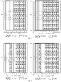
- Fig. 4 is a schematic structural diagram of an S-SSB.
- Fig. 4 shows S-SSB patterns in the cases of extended CP and normal CP when a sidelink subcarrier spacing is 60 KHz.
- S-PSS and S-SSS in each S-SSB each occupy 2 symbols, and PSBCH occupies 6 symbols.
- PSBCH occupies 6 symbols.
- inter-symbol crosstalk due to multipath delay is avoided, thereby the success rate of detecting PSS and SSS sequences is improved, and the success rate of decoding the PSBCH is also improved and the coverage radius requirement of NR V2X is met.
- Fig. 5 is a schematic structural diagram of an S-SSB in embodiment 1.
- one slot configured with extended CP includes one S-SSB, and S-PSS is located in symbols #1 and #2, S-SSS is located in symbols #3 and #4, PSBCH is located in symbols #5 to #10, and all the symbols where PSBCH is located have a DMRS embedded in a comb-like manner.
- DMRS and S-SSS are used for channel estimation, and the channel estimate is used for PSBCH decoding.
- the S-SSB pattern in the slot configured with normal CP is different from the S-SSB pattern in the slot configured with extended CP, and the PSBCH of the S-SSB in the slot configured with normal CP occupies two more symbols.
- an extended CP is used to transmit S-SSB, and both S-PSS and S-SSS are sent using two symbols, so that the extended CP can ensure that the coverage requirement of NR V2X is met.
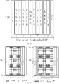
- Fig. 6 is a schematic structural diagram of an S-SSB in embodiment 2.
- one slot configured with extended CP includes one S-SSB, and S-PSS is located in symbols #1 and #2, S-SSS is located in symbols #3 and #10, PSBCH is located in symbols #4 to #9, and all the symbols where PSBCH is located have a DMRS embedded in a comb-like manner.
- DMRS and S-SSS are used for channel estimation, and the channel estimate is used for PSBCH decoding.
- the S-SSB pattern in the slot configured with normal CP is different from the S-SSB pattern in the slot configured with extended CP, and the PSBCH of the S-SSB in the slot configured with normal CP occupies two more symbols.
- an extended CP is used to transmit S-SSB, and both S-PSS and S-SSS are sent using two symbols.
- the use of extended CP can ensure that the coverage requirement of NR V2X is met, and there are 6 symbols between two S-SSS symbols, which improves the performance of frequency offset estimation.
- Fig. 7 is a schematic structural diagram of an S-SSB in embodiment 3.
- one slot configured with extended CP includes one S-SSB, and S-PSS is located in symbols #2 and #3, S-SSS is located in symbols #1 and #4, PSBCH is located in symbols #5 to #10, and all the symbols where PSBCH is located have a DMRS embedded in a comb-like manner.
- DMRS and S-SSS are used for channel estimation, and the channel estimate is used for PSBCH decoding.
- the S-SSB pattern in the slot configured with normal CP is different from the S-SSB pattern in the slot configured with extended CP, and the PSBCH of the S-SSB in the slot configured with normal CP occupies two more symbols.
- an extended CP is used to transmit S-SSB, and both S-PSS and S-SSS are sent using two symbols.
- the use of extended CP can ensure that the coverage requirement of NR V2X is met, and there are 2 symbols between two S-SSS symbols, which improves the performance of frequency offset estimation.
- Fig. 8 is a schematic structural diagram of an S-SSB in embodiment 4.
- one slot configured with extended CP includes one S-SSB, and S-PSS is located in symbols #1 and #2, S-SSS is located in symbols #4 and #5, PSBCH is located in symbols #3, #6 to #10, and all the symbols where PSBCH is located have a DMRS embedded in a comb-like manner.
- DMRS and S-SSS are used for channel estimation, and the channel estimate is used for PSBCH decoding.
- the S-SSB pattern in the slot configured with normal CP is different from the S-SSB pattern in the slot configured with extended CP, and the PSBCH of the S-SSB in the slot configured with normal CP occupies two more symbols.
- an extended CP is used to transmit S-SSB, and both S-PSS and S-SSS are sent using two symbols.
- the use of extended CP can ensure that the coverage requirement of NR V2X is met, and two S-PSS symbols are followed by PSBCH, which avoids the impact of transition time on S-SSS detection.
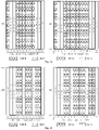
- Fig. 9 is a schematic structural diagram of an S-SSB in embodiment 5.
- one slot configured with extended CP includes one S-SSB, and S-PSS is located in symbols #1 and #2, S-SSS is located in symbols #3 and #4, PSBCH is located in symbols #0, #5 to #10, and all the symbols where PSBCH is located have a DMRS embedded in a comb-like manner.
- DMRS and S-SSS are used for channel estimation, and the channel estimate is used for PSBCH decoding.
- the S-SSB pattern in the slot configured with normal CP is different from the S-SSB pattern in the slot configured with extended CP, and the PSBCH of the S-SSB in the slot configured with normal CP occupies two more symbols.
- an extended CP is used to transmit S-SSB, and both S-PSS and S-SSS are sent using two symbols.
- the use of extended CP can ensure that the coverage requirement of NR V2X is met, and the PSBCH at symbol #0 serves as AGC, which reduces the code rate of PSBCH and improves the decoding performance of PSBCH.
- Fig. 10 is a schematic structural diagram of an S-SSB in embodiment 6.
- one slot configured with extended CP includes one S-SSB, and S-PSS is located in symbols #1 and #2, S-SSS is located in symbols #3 and #10, PSBCH is located in symbols #0, #4 to #9, and all the symbols where PSBCH is located have a DMRS embedded in a comb-like manner.
- DMRS and S-SSS are used for channel estimation, and the channel estimate is used for PSBCH decoding.
- the S-SSB pattern in the slot configured with normal CP is different from the S-SSB pattern in the slot configured with extended CP, and the PSBCH of the S-SSB in the slot configured with normal CP occupies two more symbols.
- an extended CP is used to transmit S-SSB, and both S-PSS and S-SSS are sent using two symbols.
- the use of extended CP can ensure that the coverage requirement of NR V2X is met, and the PSBCH at symbol #0 serves as AGC, which reduces the code rate of PSBCH and improves the decoding performance of PSBCH.
- Fig. 11 is a schematic structural diagram of an S-SSB in embodiment 7.
- one slot configured with extended CP includes one S-SSB, and S-PSS is located in symbols #2 and #3, S-SSS is located in symbols #1 and #4, PSBCH is located in symbols #0, #5 to #10, and all the symbols where PSBCH is located have a DMRS embedded in a comb-like manner.
- DMRS and S-SSS are used for channel estimation, and the channel estimate is used for PSBCH decoding.
- the S-SSB pattern in the slot configured with normal CP is different from the S-SSB pattern in the slot configured with extended CP, and the PSBCH of the S-SSB in the slot configured with normal CP occupies two more symbols.
- an extended CP is used to transmit S-SSB, and both S-PSS and S-SSS are sent using two symbols.
- the use of extended CP can ensure that the coverage requirement of NR V2X is met, and the PSBCH at symbol #0 serves as AGC, which reduces the code rate of PSBCH and improves the decoding performance of PSBCH.
- Fig. 12 is a schematic structural diagram of an S-SSB in embodiment 8.
- one slot configured with extended CP includes one S-SSB, and S-PSS is located in symbols #1 and #2, S-SSS is located in symbols #4 and #5, PSBCH is located in symbols #0, #3, and #6 to #10, and all the symbols where PSBCH is located have a DMRS embedded in a comb-like manner.
- DMRS and S-SSS are used for channel estimation, and the channel estimate is used for PSBCH decoding.
- the S-SSB pattern in the slot configured with normal CP is different from the S-SSB pattern in the slot configured with extended CP, and the PSBCH of the S-SSB in the slot configured with normal CP occupies two more symbols.
- an extended CP is used to transmit S-SSB, and both S-PSS and S-SSS are sent using two symbols.
- the use of extended CP can ensure that the coverage requirement of NR V2X is met, and the PSBCH at symbol #0 serves as AGC, which reduces the code rate of PSBCH and improves the decoding performance of PSBCH.
- two S-PSS symbols are followed by PSBCH, which avoids the impact of transition time on S-SSS detection.
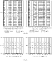
- Fig. 13 is a schematic structural diagram of an S-SSB in embodiment 9.
- one slot configured with extended CP includes one S-SSB, and S-PSS is located in symbols #1 and #2, S-SSS is located in symbols #3 and #10, PSBCH is located in symbols #4 to #9, and the symbols where PSBCH is located do not include a DMRS.
- S-SSS is used for channel estimation, and the channel estimate is used for PSBCH decoding.
- two symbols in which S-SSS is sent repetitively are separated by six symbols in the time domain.
- the S-SSB pattern in the slot configured with normal CP is different from the S-SSB pattern in the slot configured with extended CP, and the PSBCH of the S-SSB in the slot configured with normal CP occupies two more symbols.
- both S-PSS and S-SSS are sent using two symbols, and the two symbols for transmission of S-SSS are separated by 6 symbols in the time domain, which can improve the performance of frequency offset estimation, and further decrease the decoding BLER of the PSBCH.
- the S-SSB pattern does not include any DMRS, it can be applied to both the CP-OFDM waveform and the DFT-s-OFDM waveform.
- Fig. 14 is a schematic structural diagram of an S-SSB in embodiment 10.
- one slot configured with extended CP includes one S-SSB, and S-PSS is located in symbols #1 and #2, S-SSS is located in symbols #3 and #7, PSBCH is located in symbols #4 to #6, #8 and #10.
- the DMRS is not included in the symbols where the PSBCH is located, and S-SSS is used for channel estimation, and the channel estimate is used for PSBCH decoding.
- two symbols in which S-SSS is sent repetitively are separated by 3 symbols in the time domain.
- the S-SSB pattern in the slot configured with normal CP is different from the S-SSB pattern in the slot configured with extended CP, and the PSBCH of the S-SSB in the slot configured with normal CP occupies two more symbols.
- both S-PSS and S-SSS are sent using two symbols, and the two symbols for transmission of S-SSS are separated by 3 symbols in the time domain, which can improve the performance of frequency offset estimation, and further decrease the decoding BLER of the PSBCH.
- the S-SSB pattern does not include any DMRS, it can be applied to both the CP-OFDM waveform and the DFT-s-OFDM waveform.
- Fig. 15 is a schematic structural diagram of an S-SSB in embodiment 11.
- one slot configured with extended CP includes one S-SSB, and S-PSS is located in symbols #1 and #2, S-SSS is located in symbols #3 and #10, PSBCH is located in symbols #4, #6, #8 and #10, and DMRS is located in symbols #5 and #7.
- DMRS and S-SSS are used for channel estimation, and the channel estimate is used for PSBCH decoding. Two symbols in which S-SSS is sent repetitively are separated by 6 symbols in the time domain.
- the S-SSB pattern in the slot configured with normal CP is different from the S-SSB pattern in the slot configured with extended CP, and the PSBCH of the S-SSB in the slot configured with normal CP occupies two more symbols.
- both S-PSS and S-SSS are sent using two symbols, and the two symbols for transmission of S-SSS are separated by 6 symbols in the time domain, which can improve the performance of frequency offset estimation, and further decrease the decoding BLER of the PSBCH.
- Fig. 16 is a schematic structural diagram of an S-SSB in embodiment 12.
- one slot configured with extended CP includes one S-SSB, and S-PSS is located in symbols #1 and #2, S-SSS is located in symbols #3 and #7, PSBCH is located in symbols #4, #6, #8 and #10, and DMRS is located in symbols #5 and #9.
- DMRS and S-SSS are used for channel estimation, and the channel estimate is used for PSBCH decoding.
- Two symbols in which S-SSS is sent repetitively are separated by 3 symbols in the time domain.
- the S-SSB pattern in the slot configured with normal CP is different from the S-SSB pattern in the slot configured with extended CP, and the PSBCH of the S-SSB in the slot configured with normal CP occupies two more symbols.
- both S-PSS and S-SSS are sent using two symbols, and the two symbols for transmission of S-SSS are separated by 3 symbols in the time domain, which can improve the performance of frequency offset estimation, and further decrease the decoding BLER of the PSBCH.
- Fig. 17 is a schematic structural diagram of an S-SSB in embodiment 13.
- one slot configured with extended CP includes one S-SSB, and S-PSS is located in symbols #1 and #2, S-SSS is located in symbols #9 and #10, PSBCH is located in symbols #3 to #10, and all the symbols where PSBCH is located have a DMRS embedded in a comb-like manner.
- DMRS and S-SSS are used for channel estimation, and the channel estimate is used for PSBCH decoding.
- the S-SSB pattern in the slot configured with normal CP is different from the S-SSB pattern in the slot configured with extended CP, and the PSBCH of the S-SSB in the slot configured with normal CP occupies two more symbols.
- an extended CP is used to transmit S-SSB, and both S-PSS and S-SSS are sent using two symbols.
- the use of extended CP can ensure that the coverage requirement of NR V2X is met, and two S-PSS symbols are followed by PSBCH, which avoids the impact of transition time on S-SSS detection.
- Fig. 18 is a schematic structural diagram of an S-SSB in embodiment 14.
- one slot configured with extended CP includes one S-SSB, and S-PSS is located in symbols #1 and #2, S-SSS is located in symbols #9 and #10, PSBCH is located in symbols #0, and #3 to #8, and all the symbols where PSBCH is located have a DMRS embedded in a comb-like manner.
- DMRS and S-SSS are used for channel estimation, and the channel estimate is used for PSBCH decoding.
- the S-SSB pattern in the slot configured with normal CP is different from the S-SSB pattern in the slot configured with extended CP, and the PSBCH of the S-SSB in the slot configured with normal CP occupies two more symbols.
- an extended CP is used to transmit S-SSB, and both S-PSS and S-SSS are sent using two symbols.
- the use of extended CP can ensure that the coverage requirement of NR V2X is met, and the PSBCH at symbol #0 serves as AGC, which reduces the code rate of PSBCH and improves the decoding performance of PSBCH.
- two S-PSS symbols are followed by PSBCH, which avoids the impact of transition time on S-SSS detection.
- Fig. 19 is a schematic structural diagram of an S-SSB in embodiment 15.
- one slot configured with extended CP includes one S-SSB, and S-PSS is located in symbols #1 and #2, S-SSS is located in symbols #5 and #8, PSBCH is located in symbols #3, #4, #6, #7, #9 and #10, and all the symbols where PSBCH is located have a DMRS embedded in a comb-like manner.
- DMRS and S-SSS are used for channel estimation, and the channel estimate is used for PSBCH decoding.
- the S-SSB pattern in the slot configured with normal CP is different from the S-SSB pattern in the slot configured with extended CP, and the PSBCH of the S-SSB in the slot configured with normal CP occupies two more symbols.
- an extended CP is used to transmit S-SSB, and both S-PSS and S-SSS are sent using two symbols.
- the use of extended CP can ensure that the coverage requirement of NR V2X is met.
- two S-PSS symbols are followed by PSBCH, which avoids the impact of transition time on S-SSS detection.
- Fig. 20 is a schematic structural diagram of an S-SSB in embodiment 16.
- one slot configured with extended CP includes one S-SSB, and S-PSS is located in symbols #1 and #2, S-SSS is located in symbols #5 and #8, PSBCH is located in symbols #0, #3, #4, #6, #7, #9 and #10, and all the symbols where PSBCH is located have a DMRS embedded in a comb-like manner.
- DMRS and S-SSS are used for channel estimation, and the channel estimate is used for PSBCH decoding.
- the S-SSB pattern in the slot configured with normal CP is different from the S-SSB pattern in the slot configured with extended CP, and the PSBCH of the S-SSB in the slot configured with normal CP occupies two more symbols.
- an extended CP is used to transmit S-SSB, and both S-PSS and S-SSS are sent using two symbols.
- the use of extended CP can ensure that the coverage requirement of NR V2X is met, and the PSBCH at symbol #0 serves as AGC, which reduces the code rate of PSBCH and improves the decoding performance of PSBCH.
- two S-PSS symbols are followed by PSBCH, which avoids the impact of transition time on S-SSS detection.
- the disadvantage is that S-PSS and S-SSS each occupy two symbols, and the resource overhead is relatively large.
- Fig. 21 is a schematic structural diagram of an S-SSB in embodiment 17.
- one slot configured with extended CP includes one S-SSB, and S-PSS is located in symbols #1 and #2, S-SSS is located in symbols #5 and #8, PSBCH is located in symbols #3, #4, #6, #7, #9 and #10.
- the DMRS is not included in the symbols where the PSBCH is located, and S-SSS is used for channel estimation, and the channel estimate is used for PSBCH decoding.
- two symbols in which S-SSS is sent repetitively are separated by 2 symbols in the time domain.
- the S-SSB pattern in the slot configured with normal CP is different from the S-SSB pattern in the slot configured with extended CP, and the PSBCH of the S-SSB in the slot configured with normal CP occupies two more symbols.
- both S-PSS and S-SSS are sent using two symbols, and the two symbols for transmission of S-SSS are separated by 2 symbols in the time domain, which can improve the performance of frequency offset estimation, and further decrease the decoding BLER of the PSBCH.
- the S-SSB pattern does not include any DMRS, it can be applied to both the CP-OFDM waveform and the DFT-s-OFDM waveform.
- two S-PSS symbols are followed by PSBCH, which avoids the impact of transition time on S-SSS detection.
- Fig. 22 is a schematic structural diagram of an S-SSB in embodiment 18.
- one slot configured with extended CP includes one S-SSB, and S-PSS is located in symbols #1 and #2, S-SSS is located in symbols #5 and #8, PSBCH is located in symbols #0, #3, #4, #6, #7, #9 and #10.
- the DMRS is not included in the symbols where the PSBCH is located, and S-SSS is used for channel estimation, and the channel estimate is used for PSBCH decoding.
- two symbols in which S-SSS is sent repetitively are separated by 2 symbols in the time domain.
- the S-SSB pattern in the slot configured with normal CP is different from the S-SSB pattern in the slot configured with extended CP, and the PSBCH of the S-SSB in the slot configured with normal CP occupies two more symbols.
- both S-PSS and S-SSS are sent using two symbols, and the two symbols for transmission of S-SSS are separated by 2 symbols in the time domain, which can improve the performance of frequency offset estimation, and further decrease the decoding BLER of the PSBCH.
- the PSBCH at symbol #0 serves as AGC, which reduces the code rate of PSBCH and improves the decoding performance of PSBCH.
- the S-SSB pattern does not include any DMRS, it can be applied to both the CP-OFDM waveform and the DFT-s-OFDM waveform.
- two S-PSS symbols are followed by PSBCH, which avoids the impact of transition time on S-SSS detection.
- embodiments of the present disclosure also provide a terminal acting as a sending side, a terminal acting as a receiving side, a sending apparatus, a receiving apparatus, and a storage medium. Because the principles on which these devices are based to solve the problem is similar to those underlying the method for sending the signal and the method for receiving the signal, for the implementation of these devices, references can be made to the implementations of the methods, and a redundant description is omitted herein. When the technical solutions provided in the embodiments of the present disclosure are implemented, the solutions can be implemented as follows.
- Fig. 23 is a schematic structural diagram of a terminal acting as a sending side. As shown in Fig. 23 , the terminal includes: a processor 2300, configured to read a program in a memory 2320 and execute following process:
- that the first SSB pattern is different from the second SSB pattern refers to that:
- M is 6 or 7; or, N is 8 or 9.
- two OFDM symbols in the SSB that are used for transmission of the SSS are discontinuous OFDM symbols in a time domain.
- the SSB further includes the PBCH occupying 5 or more OFDM symbols.
- the first OFDM symbol of the slot where the SSB is located is allocated for the PBCH, and the first OFDM symbol is used for implementing the AGC function.
- a channel estimation is performed by using a DMRS embedded in the PBCH and PBCH decoding is performed based on a result of the channel estimation when the SSB is sent by using a CP-OFDM waveform; or,
- the SSB is an S-SSB
- the PSS is an S-PSS
- the SSS is an S-SSS
- the PBCH is a PSBCH.
- the bus architecture may include any number of interconnected buses and bridges, and connect various circuits including one or more processors represented specifically by the processor 2300 and a memory represented by the memory 2320.
- the bus architecture can also connect various other circuits such as peripheral devices, voltage regulators, power management circuits, etc., which are all known in the field, and therefore, will not be further described herein.
- the bus interface provides the interface.
- the transceiver 2310 may be a plurality of elements, that is, including a transmitter and a receiver, and provide a unit for communicating with various other devices on the transmission medium.
- the user interface 2330 may also be an interface capable of connecting externally and internally with required device.
- the connected device includes but is not limited to a keypad, a display, a speaker, a microphone, a joystick, etc.
- the processor 2300 is responsible for managing the bus architecture and general processing, and the memory 2320 can store data used by the processor 2300 when performing operations.
- Fig. 24 is a schematic structural diagram of a terminal acting as a receiving side. As shown in Fig. 24 , the terminal includes: a processor 2400, configured to read a program in a memory 2420 and execute following process:
- that the first SSB pattern is different from the second SSB pattern refers to that:
- M is 6 or 7; or, N is 8 or 9.
- two OFDM symbols in the SSB that are used for transmission of the SSS are discontinuous OFDM symbols in a time domain.
- the SSB further includes the PBCH occupying 5 or more OFDM symbols.
- the first OFDM symbol of the slot where the SSB is located is allocated for the PBCH, and the first OFDM symbol is used for implementing the AGC function.
- a channel estimation is performed by using a DMRS embedded in the PBCH and PBCH decoding is performed based on a result of the channel estimation when the SSB is sent by using a CP-OFDM waveform; or,
- the SSB is an S-SSB
- the PSS is an S-PSS
- the SSS is an S-SSS
- the PBCH is a PSBCH.
- the bus architecture may include any number of interconnected buses and bridges, and connect various circuits including one or more processors represented specifically by the processor 2400 and a memory represented by the memory 2420.
- the bus architecture can also connect various other circuits such as peripheral devices, voltage regulators, power management circuits, etc., which are all known in the field, and therefore, will not be further described herein.
- the bus interface provides the interface.
- the transceiver 2410 may be a plurality of elements, that is, including a transmitter and a receiver, and provide a unit for communicating with various other devices on the transmission medium.
- the user interface 2430 may also be an interface capable of connecting externally and internally with required device.
- the connected device includes but is not limited to a keypad, a display, a speaker, a microphone, a joystick, etc.
- the processor 2400 is responsible for managing the bus architecture and general processing, and the memory 2420 can store data used by the processor 2400 when performing operations.
- An embodiment of the present disclosure provides an apparatus for sending a signal, including: a sending module, configured to send an SSB, wherein the SSB includes a PSS, an SSS and a PBCH, the PSS occupying two OFDM symbols, and the SSS occupying two OFDM symbols, wherein an SSB pattern used in a slot where the SSB is located is a first SSB pattern when a normal CP is configured, the SSB pattern used in the slot where the SSB is located is a second SSB pattern when an extended CP is configured, and the first SSB pattern is different from the second SSB pattern.
- An embodiment of the present disclosure provides an apparatus for receiving a signal, including: a receiving module, configured to receive an SSB, wherein the SSB includes a PSS, an SSS and a PBCH, the PSS occupying two OFDM symbols, and the SSS occupying two OFDM symbols, wherein an SSB pattern used in a slot where the SSB is located is a first SSB pattern when a normal CP is configured, the SSB pattern used in the slot where the SSB is located is a second SSB pattern when an extended CP is configured, and the first SSB pattern is different from the second SSB pattern; a demodulation module, configured to demodulate the SSB.
- An embodiment of the present disclosure provides a computer-readable storage medium storing thereon a computer program, wherein the computer program is configured to be executed by a processor to implement the above-mentioned method for sending a signal and/or method for receiving a signal.
- the embodiments of the present disclosure provide a technical solution for sending and receiving a signal, and this technical solution can be used in NR V2X sidelink communication.
- the SSB pattern used in the case of normal CP is different from the SSB pattern used in the case of extended CP.
- two OFDM symbols are used to transmit the PSS, while two OFDM symbols are used to transmit the SSS.
- the difference between the SSB patterns in the cases of normal CP and extended CP lies in that the quantity of symbols occupied by PBCH is different; specifically, PBCH occupies 8 or 9 symbols in the case of normal CP, while PBCH occupies 6 or 7 symbols in the case of extended CP.
- the PBCH occupies at least 5 OFDM symbols.
- the first symbol is allocated for PBCH to implement the AGC function.
- an independent DMRS column is not included, instead, a DMRS embedded in the PBCH is used for channel estimation, and PBCH decoding is performed based on a result of the channel estimation.
- the symbols where the PBCH is located do not include the embedded DMRS, instead, the channel estimation is performed by using the SSS, and PBCH decoding is performed based on a result of the channel estimation.
- the two waveforms can share a single SSB pattern.
- an independent DMRS column is used for channel estimation, and the channel estimate is used for PBCH decoding.
- an SSB pattern for the situation where an extended CP is used may be utilized when the sidelink communication subcarrier spacing is large, to avoid inter-symbol crosstalk due to multipath delay, thus improving the success rate of detecting PSS and SSS sequences, and further improving the success rate of decoding the PBCH and ensuring that the coverage radius requirement of NR V2X is met.
- embodiments of the present disclosure may be implemented as a method, system or computer program product. Therefore, embodiments of the present disclosure may take the form of a complete hardware embodiment, complete software embodiment or combination of hardware and software. Moreover, embodiments of the present disclosure may take the form of a computer program product embodied on one or more computer usable storage media (including, but not limited to, a magnetic disk storage, optical storage or the like) storing therein computer usable program codes.
- a computer usable storage media including, but not limited to, a magnetic disk storage, optical storage or the like
- These computer program instructions may also be stored in a computer-readable storage that can direct a computer or other programmable data processing device to function in a particular manner, such that the instructions stored in the computer-readable storage produce an article of manufacture including instruction means which implement the function specified in one or more flows of the flow diagrams and/or one or more blocks of the block diagrams.
- the computer program instructions may also be loaded onto a computer or other programmable data processing device to cause a series of operational steps to be performed on the computer or other programmable device to produce a computer-implemented process, such that the instructions which are executed on the computer or other programmable device provide steps for implementing the functions specified in one or more flows of the flow diagrams and/or one or more blocks of the block diagrams.
- a determination module can be a separately provided processing element or can be integrated in certain chip of the above-mentioned device, in addition, it can also be stored in the memory of the above-mentioned device in the form of program code, which is invoked by certain processing element of the above-mentioned device to perform the functions of the above-mentioned determination module.
- modules are implemented in a similar way. Furthermore, all or some of these modules can be integrated together or can be implemented independently.
- the processing element described here may be an integrated circuit with signal processing capabilities.
- the various steps of the above-mentioned methods or the above-mentioned modules may be accomplished by integrated logic circuits in the form of hardware or by instructions in the form of software in the processor element.
- the various modules, units, subunits, or submodules may be one or more integrated circuits configured to implement the above method, e.g., one or more application specific integrated circuits (ASICs), or, one or more digital signal processors (DSPs), or, one or more field programmable gate arrays (FPGAs), etc.
- ASICs application specific integrated circuits
- DSPs digital signal processors
- FPGAs field programmable gate arrays
- the processing element may be a general purpose processor, such as a central processing unit (CPU) or other processor that can invoke program code.
- these modules may be integrated together and implemented in the form of a system-on-a-chip (SOC).
- SOC system-on-a-chip
- a and/or B and/or C indicates seven cases as follows: A alone, B alone, C alone, A and B both present, B and C both present, A and C both present, and A, B, and C all present.
- the use of "at least one of A or B" in this specification and in the claims should be understood to mean “A alone, B alone, or A and B both present”.
Landscapes
- Engineering & Computer Science (AREA)
- Signal Processing (AREA)
- Computer Networks & Wireless Communication (AREA)
- Physics & Mathematics (AREA)
- Discrete Mathematics (AREA)
- General Physics & Mathematics (AREA)
- Mathematical Physics (AREA)
- Mobile Radio Communication Systems (AREA)
- Stereo-Broadcasting Methods (AREA)
- Radar Systems Or Details Thereof (AREA)
Applications Claiming Priority (2)
| Application Number | Priority Date | Filing Date | Title |
|---|---|---|---|
| CN201910708865.6A CN112311712B (zh) | 2019-08-01 | 2019-08-01 | 一种信号的发送、接收方法、终端及装置 |
| PCT/CN2020/099335 WO2021017729A1 (zh) | 2019-08-01 | 2020-06-30 | 信号的发送、接收方法、终端及装置 |
Publications (2)
| Publication Number | Publication Date |
|---|---|
| EP4009598A1 true EP4009598A1 (de) | 2022-06-08 |
| EP4009598A4 EP4009598A4 (de) | 2022-09-28 |
Family
ID=74229177
Family Applications (1)
| Application Number | Title | Priority Date | Filing Date |
|---|---|---|---|
| EP20848671.2A Pending EP4009598A4 (de) | 2019-08-01 | 2020-06-30 | Verfahren zum senden und empfangen von signalen, endgerät und vorrichtung |
Country Status (6)
| Country | Link |
|---|---|
| US (1) | US12167351B2 (de) |
| EP (1) | EP4009598A4 (de) |
| KR (1) | KR102728675B1 (de) |
| CN (2) | CN114268530B (de) |
| TW (1) | TWI767273B (de) |
| WO (1) | WO2021017729A1 (de) |
Families Citing this family (8)
| Publication number | Priority date | Publication date | Assignee | Title |
|---|---|---|---|---|
| US12167352B2 (en) * | 2019-10-02 | 2024-12-10 | Lg Electronics Inc. | Method and device for transmitting S-SSB in NR V2X |
| CN113630861B (zh) * | 2020-05-09 | 2023-04-07 | 维沃移动通信有限公司 | 同步信号块的处理方法及装置、通信设备和可读存储介质 |
| US12041564B2 (en) * | 2020-05-22 | 2024-07-16 | Qualcomm Incorporated | Demand and response for sidelink synchronization signal block (S-SSB) transmission |
| JP7815123B2 (ja) * | 2020-08-05 | 2026-02-17 | パナソニック インテレクチュアル プロパティ コーポレーション オブ アメリカ | 端末、通信方法及び集積回路 |
| CN114727339B (zh) * | 2021-01-05 | 2026-01-20 | 中国移动通信有限公司研究院 | 一种信号的发送、接收方法、网络设备及终端 |
| KR20240004385A (ko) * | 2021-05-11 | 2024-01-11 | 엘지전자 주식회사 | 사이드링크 통신 |
| CN118104342A (zh) * | 2021-10-21 | 2024-05-28 | 富士通株式会社 | 发送信号的方法、装置和通信系统 |
| CN118900468A (zh) * | 2023-05-04 | 2024-11-05 | 中兴通讯股份有限公司 | 一种信道传输方法、通信设备及存储介质 |
Family Cites Families (23)
| Publication number | Priority date | Publication date | Assignee | Title |
|---|---|---|---|---|
| CN104767594A (zh) * | 2014-01-03 | 2015-07-08 | 北京三星通信技术研究有限公司 | Lte系统中上行传输的方法和设备 |
| CN104936166B (zh) * | 2014-03-20 | 2018-07-20 | 电信科学技术研究院 | 一种信号发送、接收方法及装置 |
| CN106411445B (zh) * | 2015-07-31 | 2019-08-27 | 南京中兴软件有限责任公司 | 一种通信系统中同步信号的发送方法、同步方法及装置 |
| WO2017132993A1 (zh) * | 2016-02-05 | 2017-08-10 | 华为技术有限公司 | 一种控制信息的传输方法及装置 |
| US9893925B1 (en) | 2016-04-01 | 2018-02-13 | Mbit Wireless, Inc. | Method and apparatus for joint time and frequency synchronization in wireless communication systems |
| US10630410B2 (en) * | 2016-05-13 | 2020-04-21 | Telefonaktiebolaget Lm Ericsson (Publ) | Network architecture, methods, and devices for a wireless communications network |
| CN107634925B (zh) * | 2016-07-18 | 2020-10-02 | 中兴通讯股份有限公司 | 同步信道的发送、接收方法及装置、传输系统 |
| CN107889229B (zh) * | 2016-09-29 | 2019-12-13 | 电信科学技术研究院 | 一种上行控制信息uci的传输方法和设备 |
| US10425264B2 (en) * | 2017-01-09 | 2019-09-24 | Lg Electronics Inc. | Method of transmitting synchronization signal and apparatus therefor |
| KR101962148B1 (ko) * | 2017-06-16 | 2019-03-26 | 엘지전자 주식회사 | 하향링크 채널을 송수신하는 방법 및 이를 위한 장치 |
| WO2018230984A1 (ko) * | 2017-06-16 | 2018-12-20 | 엘지전자 주식회사 | 동기 신호 블록을 측정하는 방법 및 이를 위한 장치 |
| WO2019022577A1 (ko) | 2017-07-28 | 2019-01-31 | 엘지전자 주식회사 | 방송 채널을 송수신하는 방법 및 이를 위한 장치 |
| WO2019022574A1 (ko) | 2017-07-28 | 2019-01-31 | 엘지전자 주식회사 | 동기 신호 블록을 송수신하는 방법 및 이를 위한 장치 |
| CN109495413B (zh) * | 2017-09-11 | 2022-04-01 | 中国移动通信有限公司研究院 | 同步信号块的传输、小区质量的测量方法、基站及终端 |
| WO2019054755A1 (ko) * | 2017-09-12 | 2019-03-21 | 엘지전자 주식회사 | 무선 통신 시스템에서 무선 신호 송수신 방법 및 장치 |
| KR102104902B1 (ko) * | 2017-11-17 | 2020-05-29 | 엘지전자 주식회사 | 물리 임의 접속 채널을 송수신하는 방법 및 이를 위한 장치 |
| US10506588B2 (en) * | 2017-11-17 | 2019-12-10 | Lg Electronics Inc. | Method and apparatus for transmitting and receiving system information |
| US10863494B2 (en) * | 2018-01-22 | 2020-12-08 | Apple Inc. | Control signaling for uplink multiple input multiple output, channel state information reference signal configuration and sounding reference signal configuration |
| EP4407916A3 (de) * | 2018-10-01 | 2024-10-09 | Guangdong Oppo Mobile Telecommunications Corp., Ltd. | Benutzergerät und verfahren zur übertragung eines synchronisationssignalblocks davon |
| CN110035028B (zh) * | 2019-03-29 | 2020-02-21 | 宇龙计算机通信科技(深圳)有限公司 | 基于非授权频谱的同步信号传输方法、装置和存储介质 |
| US11463972B2 (en) * | 2019-06-12 | 2022-10-04 | Qualcomm Incorporated | Sidelink primary and secondary synchronization signal transmission |
| US12041564B2 (en) * | 2020-05-22 | 2024-07-16 | Qualcomm Incorporated | Demand and response for sidelink synchronization signal block (S-SSB) transmission |
| KR20250004775A (ko) * | 2022-04-27 | 2025-01-08 | 애플 인크. | 비면허 nr에서의 사이드링크 ssb 송신 |
-
2019
- 2019-08-01 CN CN202111570158.9A patent/CN114268530B/zh active Active
- 2019-08-01 CN CN201910708865.6A patent/CN112311712B/zh active Active
-
2020
- 2020-06-30 KR KR1020227005954A patent/KR102728675B1/ko active Active
- 2020-06-30 WO PCT/CN2020/099335 patent/WO2021017729A1/zh not_active Ceased
- 2020-06-30 EP EP20848671.2A patent/EP4009598A4/de active Pending
- 2020-06-30 US US17/631,623 patent/US12167351B2/en active Active
- 2020-07-10 TW TW109123290A patent/TWI767273B/zh active
Also Published As
| Publication number | Publication date |
|---|---|
| KR102728675B1 (ko) | 2024-11-08 |
| US20220295425A1 (en) | 2022-09-15 |
| EP4009598A4 (de) | 2022-09-28 |
| CN114268530B (zh) | 2023-10-20 |
| TW202107927A (zh) | 2021-02-16 |
| CN114268530A (zh) | 2022-04-01 |
| CN112311712B (zh) | 2022-02-08 |
| KR20220038731A (ko) | 2022-03-29 |
| CN112311712A (zh) | 2021-02-02 |
| US12167351B2 (en) | 2024-12-10 |
| TWI767273B (zh) | 2022-06-11 |
| WO2021017729A1 (zh) | 2021-02-04 |
Similar Documents
| Publication | Publication Date | Title |
|---|---|---|
| US12167351B2 (en) | Method for sending and receiving signal, terminal and apparatus | |
| EP4068810B1 (de) | Verfahren zum senden und empfangen von sidelink-positionierungsreferenzsignalen und endgerät | |
| US12368545B2 (en) | Method and device for indicating sub-band configuration, and method and device for accessing sub-band | |
| US20220158885A1 (en) | Method for transmitting information in communication system, base station and user equipment | |
| EP3927035B1 (de) | Signalsendeverfahren, signalempfangsverfahren, netzwerkvorrichtung und endgerät | |
| US10917916B2 (en) | Method and device for transmitting PRACH signals in unauthorized spectrum | |
| US12349085B2 (en) | Signal transmission method, signal reception method, and user equipment | |
| CN110166393B (zh) | 同步信号块的发送、接收方法及装置 | |
| CN103095637A (zh) | 一种解调参考信号传输的方法和系统 | |
| CN104796218A (zh) | 信号传输方法和装置 | |
| US12238656B2 (en) | Rate matching indication method and apparatus, and device and storage medium | |
| CN111147213B (zh) | 一种信号的发送方法及终端 | |
| JP2019526966A (ja) | 信号送信方法、ネットワークデバイス、及び端末デバイス | |
| CN105530080A (zh) | 一种蜂窝通信中的laa传输方法和装置 | |
| CN107733826B (zh) | 下行信号的发送、接收方法以及发送端设备、接收端设备 | |
| CN113766648B (zh) | 一种ssb传输方法和装置及设备 | |
| CN110972252B (zh) | 信号的发送方法、波形的配置方法、终端及网络设备 | |
| CN111147405B (zh) | 一种信号的发送方法及终端 | |
| US20200028636A1 (en) | Signal transmission method and apparatus | |
| WO2021028033A1 (en) | Wireless communication system | |
| WO2024168850A1 (en) | Ssb structures for fast ue beam tracking | |
| WO2025152866A1 (zh) | 信号处理方法、装置及相关设备 | |
| KR20210138089A (ko) | 신호 전송 방법, 장치 및 기기 |
Legal Events
| Date | Code | Title | Description |
|---|---|---|---|
| STAA | Information on the status of an ep patent application or granted ep patent |
Free format text: STATUS: THE INTERNATIONAL PUBLICATION HAS BEEN MADE |
|
| PUAI | Public reference made under article 153(3) epc to a published international application that has entered the european phase |
Free format text: ORIGINAL CODE: 0009012 |
|
| STAA | Information on the status of an ep patent application or granted ep patent |
Free format text: STATUS: REQUEST FOR EXAMINATION WAS MADE |
|
| 17P | Request for examination filed |
Effective date: 20220214 |
|
| AK | Designated contracting states |
Kind code of ref document: A1 Designated state(s): AL AT BE BG CH CY CZ DE DK EE ES FI FR GB GR HR HU IE IS IT LI LT LU LV MC MK MT NL NO PL PT RO RS SE SI SK SM TR |
|
| A4 | Supplementary search report drawn up and despatched |
Effective date: 20220825 |
|
| RIC1 | Information provided on ipc code assigned before grant |
Ipc: H04W 72/04 20090101ALI20220819BHEP Ipc: H04L 27/26 20060101AFI20220819BHEP |
|
| DAV | Request for validation of the european patent (deleted) | ||
| DAX | Request for extension of the european patent (deleted) | ||
| STAA | Information on the status of an ep patent application or granted ep patent |
Free format text: STATUS: EXAMINATION IS IN PROGRESS |
|
| 17Q | First examination report despatched |
Effective date: 20240702 |