EP4009630A1 - Procede de detection d'intrusion - Google Patents
Procede de detection d'intrusion Download PDFInfo
- Publication number
- EP4009630A1 EP4009630A1 EP21212551.2A EP21212551A EP4009630A1 EP 4009630 A1 EP4009630 A1 EP 4009630A1 EP 21212551 A EP21212551 A EP 21212551A EP 4009630 A1 EP4009630 A1 EP 4009630A1
- Authority
- EP
- European Patent Office
- Prior art keywords
- camera
- motion detection
- intrusion
- verification device
- information representative
- Prior art date
- Legal status (The legal status is an assumption and is not a legal conclusion. Google has not performed a legal analysis and makes no representation as to the accuracy of the status listed.)
- Ceased
Links
Images

Classifications
-
- H—ELECTRICITY
- H04—ELECTRIC COMMUNICATION TECHNIQUE
- H04N—PICTORIAL COMMUNICATION, e.g. TELEVISION
- H04N7/00—Television systems
- H04N7/18—Closed-circuit television [CCTV] systems, i.e. systems in which the video signal is not broadcast
- H04N7/181—Closed-circuit television [CCTV] systems, i.e. systems in which the video signal is not broadcast for receiving images from a plurality of remote sources
-
- G—PHYSICS
- G08—SIGNALLING
- G08B—SIGNALLING SYSTEMS, e.g. PERSONAL CALLING SYSTEMS; ORDER TELEGRAPHS; ALARM SYSTEMS
- G08B13/00—Burglar, theft or intruder alarms
- G08B13/18—Actuation by interference with heat, light, or radiation of shorter wavelength; Actuation by intruding sources of heat, light, or radiation of shorter wavelength
- G08B13/189—Actuation by interference with heat, light, or radiation of shorter wavelength; Actuation by intruding sources of heat, light, or radiation of shorter wavelength using passive radiation detection systems
- G08B13/194—Actuation by interference with heat, light, or radiation of shorter wavelength; Actuation by intruding sources of heat, light, or radiation of shorter wavelength using passive radiation detection systems using image scanning and comparing systems
- G08B13/196—Actuation by interference with heat, light, or radiation of shorter wavelength; Actuation by intruding sources of heat, light, or radiation of shorter wavelength using passive radiation detection systems using image scanning and comparing systems using television cameras
-
- G—PHYSICS
- G08—SIGNALLING
- G08B—SIGNALLING SYSTEMS, e.g. PERSONAL CALLING SYSTEMS; ORDER TELEGRAPHS; ALARM SYSTEMS
- G08B13/00—Burglar, theft or intruder alarms
- G08B13/18—Actuation by interference with heat, light, or radiation of shorter wavelength; Actuation by intruding sources of heat, light, or radiation of shorter wavelength
- G08B13/189—Actuation by interference with heat, light, or radiation of shorter wavelength; Actuation by intruding sources of heat, light, or radiation of shorter wavelength using passive radiation detection systems
- G08B13/194—Actuation by interference with heat, light, or radiation of shorter wavelength; Actuation by intruding sources of heat, light, or radiation of shorter wavelength using passive radiation detection systems using image scanning and comparing systems
- G08B13/196—Actuation by interference with heat, light, or radiation of shorter wavelength; Actuation by intruding sources of heat, light, or radiation of shorter wavelength using passive radiation detection systems using image scanning and comparing systems using television cameras
- G08B13/19602—Image analysis to detect motion of the intruder, e.g. by frame subtraction
-
- G—PHYSICS
- G08—SIGNALLING
- G08B—SIGNALLING SYSTEMS, e.g. PERSONAL CALLING SYSTEMS; ORDER TELEGRAPHS; ALARM SYSTEMS
- G08B13/00—Burglar, theft or intruder alarms
- G08B13/18—Actuation by interference with heat, light, or radiation of shorter wavelength; Actuation by intruding sources of heat, light, or radiation of shorter wavelength
- G08B13/189—Actuation by interference with heat, light, or radiation of shorter wavelength; Actuation by intruding sources of heat, light, or radiation of shorter wavelength using passive radiation detection systems
- G08B13/194—Actuation by interference with heat, light, or radiation of shorter wavelength; Actuation by intruding sources of heat, light, or radiation of shorter wavelength using passive radiation detection systems using image scanning and comparing systems
- G08B13/196—Actuation by interference with heat, light, or radiation of shorter wavelength; Actuation by intruding sources of heat, light, or radiation of shorter wavelength using passive radiation detection systems using image scanning and comparing systems using television cameras
- G08B13/19639—Details of the system layout
- G08B13/19641—Multiple cameras having overlapping views on a single scene
-
- G—PHYSICS
- G08—SIGNALLING
- G08B—SIGNALLING SYSTEMS, e.g. PERSONAL CALLING SYSTEMS; ORDER TELEGRAPHS; ALARM SYSTEMS
- G08B13/00—Burglar, theft or intruder alarms
- G08B13/18—Actuation by interference with heat, light, or radiation of shorter wavelength; Actuation by intruding sources of heat, light, or radiation of shorter wavelength
- G08B13/189—Actuation by interference with heat, light, or radiation of shorter wavelength; Actuation by intruding sources of heat, light, or radiation of shorter wavelength using passive radiation detection systems
- G08B13/194—Actuation by interference with heat, light, or radiation of shorter wavelength; Actuation by intruding sources of heat, light, or radiation of shorter wavelength using passive radiation detection systems using image scanning and comparing systems
- G08B13/196—Actuation by interference with heat, light, or radiation of shorter wavelength; Actuation by intruding sources of heat, light, or radiation of shorter wavelength using passive radiation detection systems using image scanning and comparing systems using television cameras
- G08B13/19654—Details concerning communication with a camera
- G08B13/19656—Network used to communicate with a camera, e.g. WAN, LAN, Internet
Definitions
- the present invention relates to the field of surveillance and relates more particularly to an intrusion detection method aimed at avoiding false detections by surveillance camera.
- a camera can detect a change in the environment. For example, the camera identifies a change between two images acquired in a predefined time interval, such as for example a modification of the light intensity of one or more pixels, and thus detects a movement. A motion detection made by a camera is then interpreted as an intrusion, which generates an alarm. However, it happens that movements of the environment, such as for example trees moving by the action of the wind, generate intrusion detections when no intruder is present.
- An object of the present invention is to propose an intrusion detection method implemented by a verification device, connected to at least two cameras, and comprising the steps of: receiving information representative of a first motion detection coming from a first camera; recording information representative of a moment of the first motion detection in association with an identifier of the first camera having carried out said first motion detection; receiving information representing a second motion detection from a second camera; recording information representative of a moment of the second motion detection in association with an identifier of the second camera having carried out said second motion detection.
- the process includes further a step of detecting an intrusion if a time interval between the instant of the first motion detection and the instant of the second motion detection is less than a predefined duration.
- the verification device implementing the intrusion detection method is located at a distance from the first and second cameras, and the step of detecting an intrusion includes verifying that the first camera and the second camera are placed on the same monitoring site.
- the method further comprises a step of sending an alarm message to an alarm center when an intrusion is detected.
- the invention also relates to a verification device, connected to two cameras and comprising: means for receiving information representative of a first motion detection originating from a first camera; means for recording information representative of a moment of the first motion detection in association with an identifier of the first camera having carried out said first motion detection; means for receiving information representative of a second motion detection originating from a second camera; means for recording information representative of a moment of the second motion detection in association with an identifier of the second camera having carried out said second motion detection; and means for detecting an intrusion if a time interval between the instant of the first motion detection and the instant of the second motion detection is less than a predefined duration.
- the invention also relates to an intrusion detection system comprising at least two cameras arranged on the same monitoring site, an alarm center and the verification device mentioned above.
- each camera of the intrusion detection system is oriented in a different direction from another camera so that the field of view of one camera is separate from the field of view of another camera.
- the invention also relates to a computer program, which can be stored on a medium and/or downloaded from a communication network, in order to be read by a processor.
- This computer program includes instructions for implementing the method mentioned above in any of their embodiments, when said program is executed by the processor.
- the invention also relates to an information storage medium storing such a computer program.
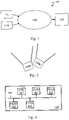
- the Fig. 1 schematically illustrates an intrusion detection system 100.
- the intrusion detection system comprises at least two cameras 110a and 110b, arranged on the same monitoring site, a verification device 120 and an alarm center 130.
- Each camera 110a, 110b continuously acquires images of the environment and detects movements by image analysis. To detect a movement, the camera 110a, 110b can for example identify if a change is observed between two images acquired in a first predefined time interval, for one or more areas of the image. Each image acquired by the camera 110a, 110b being subdivided into zones such as pixels or sets of pixels. A change of an area between two images can be for example a modification of the light intensity or a change of color of said zone. Additionally, camera 110a, 110b may count a number of areas for which a change is identified within a second predefined time interval. The camera 110a, 110b detects movement if said number of zones is greater than a predefined quantity. When a camera 110a, 110b detects a movement, the camera 110a, 110b in question transmits a message representative of a detection of movement to the verification device 120.
- Cameras 110a, 110b of the intrusion detection system 100 can be placed on different monitoring sites. Cameras 110a, 110b of the intrusion detection system 100 can thus belong to different monitoring sites.
- the surveillance site to which each camera 110a, 110b belongs is known to the verification device 120.
- verification device 120 receives a message representative of motion detection from said camera 110a, 110b.
- the verification device 120 determines that there is an intrusion on a surveillance site when at least two separate cameras 110a, 110b and arranged on said surveillance site transmit a message representative of a motion detection in a time interval less than a predefined time. When this is the case, the verification device 120 transmits an alarm message to the alarm center 130.
- the verification device 120 comprises a video platform which receives information representative of motion detection transmitted by the cameras 110a, 110b and centralizes it.
- Verification device 120 further comprises a rules engine which receives information representative of motion detection from the video platform, determines whether there is an intrusion and identifies the monitoring site concerned.
- the verification device 120 further includes a centralized home automation application for each monitoring site. When an intrusion detection on a surveillance site has been determined by the rule engine, the centralized home automation application of the surveillance site in question receives information representative of an intrusion detection and then transmits a message d alarm to the alarm center 130.
- the video platform and the rule engine can be implemented by software solutions hosted on servers accessible via the Internet. Thus, it is possible to perform intrusion detections on different monitoring sites using the same set of software solutions, common to the various monitoring sites, and located remotely from said monitoring sites.
- the Fig. 2 schematically illustrates an example of orientation of two cameras 110a, 110b arranged on the same monitoring site.
- Each camera 110a is oriented in a different direction from another camera 110b at the same monitoring site so that the field of view of a camera 110a is different and disjoint from a separate camera 110b.
- the same fixed element of the environment, but capable of generating motion detection such as a tree or a plant cannot be imaged by two separate cameras 110a, 110b, which makes it possible to avoid false detection.
- an exclusion zone can be configured on said camera 110a.
- the exclusion zone is a zone of the image acquired by said camera 110a corresponding to the part of the field of view of the camera 110a covering the field of view of the other camera 110b.
- the exclusion zone is then considered invisible by the camera 110a.
- the camera 110a therefore cannot detect motion in said exclusion zone and cannot take into account any change in the exclusion zone to perform motion detection.
- the field of view of the camera 110a analyzed during motion detection does not overlap the field of view of another distinct camera 110b.
- the Fig. 3 schematically illustrates an intrusion detection method implemented by the verification device 120.
- the verification device 120 waits for motion detection.
- the verification device 120 receives, from a first camera 110a, information representative of a first motion detection and identifies said first camera 110a having carried out said first motion detection.
- the verification device 120 records in a table, in association with an identifier of the first camera 110a, information representative of the instant t 1 of the first motion detection.
- the time of motion detection corresponds for example to a time at which motion detection was performed or to a time at which the verification device 120 received the information representative of motion detection.
- the verification device 120 then performs a step 304.
- the verification device 120 receives, from a second camera 110b, information representative of a second motion detection and identifies said first camera 110a having carried out said second motion detection.
- the verification device 120 records in a table, in association with an identifier of the second camera 110b, information representative of the instant t 2 of the second motion detection. Verifier 120 then performs step 304.
- step 303a in the case where information representative of a previous motion detection instant is already recorded following a previous motion detection performed by the first camera 110a (respectively the second camera 110b), the verification device 120 replaces said information representative of a previous instant of motion detection by information representative of the instant t 1 of the first motion detection (respectively of the instant t 2 of the second most recent motion detection). The information representative of a previous motion detection instant is then erased by the verification device 120.
- the verification device 120 replaces information representative of a previous motion detection instant with information representative of a new motion detection instant (for example the instant t 1 of the first motion detection) only when a predefined time has elapsed between the previous motion detection time and the new motion detection time.
- the verification device 120 then erases the information representative of the previous instant of motion detection so as to keep only a single piece of information representative of an instant of motion detection performed by a camera 110a, 110b. Otherwise, if motion detection is performed by a camera 110a, 110b before the predefined time has elapsed since a previous motion detection instant performed by said camera 110a, 110b then the verification device 120 does not record nothing.
- the verification device 120 successively records in the table, in association with an identifier of the first camera 110a (respectively of the second camera 110b), each piece of information representing a moment of motion detection.
- the checking device 120 checks in the table whether two motion detections made by two distinct cameras 110a, 110b are recorded. In other words, the verification device 120 verifies whether a first motion detection performed by a first camera 110a is recorded and whether a second motion detection performed by a second camera 110b, distinct from the first camera 110a, is recorded. If so, the verification device 120 performs a step 305. Otherwise, the verification device 120 again performs the step 301.
- the verification device 120 further verifies whether the second camera 110b belongs to the same monitoring site as the first camera 110a. If so, the verification device 120 performs a step 306. Otherwise, the verification device 120 again performs the step 301.
- the verification device 120 calculates a time interval between the instant t 1 of the first motion detection and the instant t 2 of the second motion detection. In the case where several second motion detections are performed by different second cameras 110b, distinct from the first camera 110a, the verification device 120 chooses the instant t 2 of the most recent second motion detection.
- a single moment ti (respectively t 2 ) of motion detection performed by the same camera 110a (respectively 110b) is recorded at a given moment and is therefore taken into account to calculate said time interval.
- the verification device chooses the most recent instant t 1 of the first motion detection (respectively t 2 of the second motion detection).
- the verification device 120 compares an absolute value of said time interval to a predefined duration. If the absolute value of said time interval is less than the predefined duration, the verification device 120 determines that there is an intrusion on the site monitoring and performs step 307. Otherwise, the verification device 120 again performs step 301.
- the verification device 120 erases the information representative of the times t 1 and t 2 of the first and second motion detections then performs a step 308.
- the verification device 120 transmits an alarm message to the alarm center 130.
- the rules engine of the verification device 120 transmits information representative of an intrusion detection to an application centralized home automation system, which transmits an alarm message to the alarm center 130.
- the Fig. 4 schematically illustrates an example of hardware architecture of the verification device 120.
- the verification device 120 then comprises, connected by a communication bus 210; a processor or CPU (Central Processing Unit) 401; a random access memory RAM 402; a read-only memory ROM 403; a storage unit 404, such as a hard disk HDD (“Hard Disk Drive” in English), or a storage medium reader, such as a card reader SD (“Secure Digital” in English); and a COM interface 405 allowing communication with the cameras 110a, 110b, and the alarm center 130.
- a communication bus 210 a processor or CPU (Central Processing Unit) 401
- a random access memory RAM 402 random access memory RAM 402
- a read-only memory ROM 403 such as a hard disk HDD (“Hard Disk Drive” in English), or a storage medium reader, such as a card reader SD (“Secure Digital” in English)
- COM interface 405 allowing communication with the cameras 110a, 110b
- CPU 401 is capable of executing instructions loaded into RAM 402 from ROM 403, external memory (such as an SD card), storage media, or a network of communication. When verifier 120 is powered up, CPU 401 is able to read instructions from RAM 402 and execute them. These instructions form a computer program causing the implementation, by the processor CPU 401, of all or part of the steps described here in relation to the verification device 120.
- All or part of said steps can thus be implemented in software form by executing a set of instructions by a programmable machine, such as a DSP (Digital Signal Processor) or a microcontroller, or be implemented in hardware form. by a dedicated machine or component, such as an FPGA (Field-Programmable Gate Array) or an ASIC (Application-Specific Integrated Circuit).
- a programmable machine such as a DSP (Digital Signal Processor) or a microcontroller
- a dedicated machine or component such as an FPGA (Field-Programmable Gate Array) or an ASIC (Application-Specific Integrated Circuit).
- the verification device 120 thus comprises electronic circuitry configured to implement all or part of the steps described here in relation to the verification device 120.
Landscapes
- Physics & Mathematics (AREA)
- General Physics & Mathematics (AREA)
- Engineering & Computer Science (AREA)
- Multimedia (AREA)
- Signal Processing (AREA)
- Computer Vision & Pattern Recognition (AREA)
- Alarm Systems (AREA)
- Burglar Alarm Systems (AREA)
Abstract
Description
- La présente invention concerne le domaine de la surveillance et concerne plus particulièrement un procédé de détection d'intrusion visant à éviter les fausses détections par caméra de surveillance.
- L'utilisation de caméras permet d'effectuer la surveillance d'un site comme par exemple une maison ou une propriété. Par analyse d'images, une caméra peut détecter une modification de l'environnement. Par exemple la caméra identifie un changement entre deux images acquises dans un intervalle de temps prédéfini, comme par exemple une modification de l'intensité lumineuse d'un ou plusieurs pixels et détecte ainsi un mouvement. Une détection de mouvement effectuée par une caméra est alors interprétée comme une intrusion, ce qui génère une alarme. Toutefois, il arrive que des mouvements de l'environnement, comme par exemple des arbres bougeant par l'action du vent, génèrent des détections d'intrusion alors qu'aucun intrus n'est présent.
- Il est alors souhaitable de pallier ces inconvénients de l'état de la technique.
- Il est notamment souhaitable de fournir une solution qui permette d'éviter des fausses détections d'intrusion. Il est en outre souhaitable de fournir une solution qui permette d'utiliser des caméras existantes sans modifier les procédés de détection de mouvements qu'elles utilisent.
- Un objet de la présente invention est de proposer un procédé de détection d'intrusion implémenté par un dispositif de vérification, connecté à au moins deux caméras, et comportant les étapes de : recevoir une information représentative d'une première détection de mouvement en provenance d'une première caméra ; enregistrer une information représentative d'un instant de la première détection de mouvement en association avec un identifiant de la première caméra ayant effectué ladite première détection de mouvement ; recevoir une information représentative d'une deuxième détection de mouvement en provenance d'une deuxième caméra ; enregistrer une information représentative d'un instant de la deuxième détection de mouvement en association avec un identifiant de la deuxième caméra ayant effectué ladite deuxième détection de mouvement. Le procédé comporte en outre une étape de détecter une intrusion si un intervalle de temps entre l'instant de la première détection de mouvement et l'instant de la deuxième détection de mouvement est inférieur à une durée prédéfinie.
- Ainsi, il est possible de détecter une intrusion en utilisant des procédés de détection de mouvement implémentés par des caméras existantes tout en évitant de fausses détections.
- Selon un mode de réalisation particulier, le dispositif de vérification implémentant le procédé de détection d'intrusion est situé à distance des première et deuxième caméras, et l'étape de détection d'une intrusion comporte de vérifier que la première caméra et la deuxième caméra sont disposées sur un même site de surveillance.
- Ainsi, il est possible d'effectuer une détection d'intrusion à distance. De plus, il est possible d'effectuer de manière centralisée une détection d'intrusion de différents sites de surveillance.
- Selon un mode de réalisation particulier, le procédé comporte en outre une étape d'envoyer un message d'alarme à une centrale d'alarme lorsqu'une intrusion est détectée.
- Ainsi, il est possible d'éviter une fausse détection d'intrusion et de générer une alarme lorsqu'une intrusion est détectée.
- L'invention concerne également un dispositif de vérification, connecté à deux caméras et comportant : des moyens pour recevoir une information représentative d'une première détection de mouvement en provenance d'une première caméra ; des moyens pour enregistrer une information représentative d'un instant de la première détection de mouvement en association avec un identifiant de la première caméra ayant effectué ladite première détection de mouvement ; des moyens pour recevoir une information représentative d'une deuxième détection de mouvement en provenance d'une deuxième caméra ; des moyens pour enregistrer une information représentative d'un instant de la deuxième détection de mouvement en association avec un identifiant de la deuxième caméra ayant effectué ladite deuxième détection de mouvement ; et des moyens pour détecter une intrusion si un intervalle de temps entre l'instant de la première détection de mouvement et l'instant de la deuxième détection de mouvement est inférieur à une durée prédéfinie.
- L'invention concerne également un système de détection d'intrusion comportant au moins deux caméras disposées sur un même site de surveillance, une centrale d'alarme et le dispositif de vérification mentionné ci-dessus.
- Selon un mode de réalisation particulier, chaque caméra du système de détection d'intrusion est orientée dans une direction différente d'une autre caméra de sorte que le champ de vision d'une caméra est disjoint du champ de vision d'une autre caméra.
- L'invention concerne également un programme d'ordinateur, qui peut être stocké sur un support et/ou téléchargé d'un réseau de communication, afin d'être lu par un processeur. Ce programme d'ordinateur comprend des instructions pour implémenter le procédé mentionné ci-dessus dans l'un quelconque de leurs modes de réalisation, lorsque ledit programme est exécuté par le processeur. L'invention concerne également un support de stockage d'informations stockant un tel programme d'ordinateur.
- Les caractéristiques de l'invention mentionnées ci-dessus, ainsi que d'autres, apparaîtront plus clairement à la lecture de la description suivante d'au moins un exemple de réalisation, ladite description étant faite en relation avec les dessins joints, parmi lesquels :
- [
Fig. 1 ] illustre schématiquement un système de détection d'intrusion comportant des caméras, un dispositif de vérification et une centrale d'alarme ; - [
Fig. 2 ] illustre schématiquement une architecture matérielle du dispositif de vérification implémentant un procédé de détection d'intrusion ; - [
Fig. 3 ] illustre schématiquement le procédé de détection d'intrusion implémenté par le dispositif de vérification ; et - [
Fig. 4 ] illustre schématiquement un exemple d'architecture matérielle du dispositif de vérification. - La
Fig. 1 illustre schématiquement un système de détection d'intrusion 100. Le système de détection d'intrusion comporte au moins deux caméras 110a et 110b, disposées sur un même site de surveillance, un dispositif de vérification 120 et une centrale d'alarme 130. - Chaque caméra 110a, 110b acquière en permanence des images de l'environnement et détecte des mouvements par analyse d'images. Pour détecter un mouvement, la caméra 110a, 110b peut par exemple identifier si un changement est observé entre deux images acquises dans un premier intervalle de temps prédéfini, pour une ou plusieurs zones de l'image. Chaque image acquise par la caméra 110a, 110b étant subdivisée en zones telles que des pixels ou des ensembles de pixels. Un changement d'une zone entre deux images peut être par exemple une modification de l'intensité lumineuse ou un changement de couleur de ladite zone. En outre, la caméra 110a, 110b peut compter un nombre de zones pour lesquelles un changement est identifié dans un second intervalle de temps prédéfini. La caméra 110a, 110b détecte un mouvement si ledit nombre de zones est supérieur à une quantité prédéfinie. Lorsqu'une caméra 110a, 110b détecte un mouvement, la caméra 110a, 110b en question transmet un message représentatif d'une détection de mouvement au dispositif de vérification 120.
- Des caméras 110a, 110b du système de détection d'intrusion 100 peuvent être disposées sur des sites de surveillance différents. Des caméras 110a, 110b du système de détection d'intrusion 100 peuvent ainsi appartenir à des sites de surveillance différents. Dans ce mode de réalisation, le site de surveillance auquel appartient chaque caméra 110a, 110b est connu du dispositif de vérification 120.
- A chaque détection de mouvement effectuée par une caméra 110a, 110b, le dispositif de vérification 120 reçoit un message représentatif d'une détection de mouvement en provenance de ladite caméra 110a, 110b. Le dispositif de vérification 120 détermine qu'il y a une intrusion sur un site de surveillance lorsqu'au moins deux caméras 110a, 110b distinctes et disposées sur ledit site de surveillance transmettent un message représentatif d'une détection de mouvement dans un intervalle de temps inférieur à une durée prédéfinie. Lorsque c'est le cas, le dispositif de vérification 120 transmet un message d'alarme à la centrale d'alarme 130.
- Selon un mode de réalisation particulier, le dispositif de vérification 120 comporte une plateforme vidéo qui réceptionne des informations représentatives de détection de mouvement transmises par les caméras 110a, 110b et les centralise. Le dispositif de vérification 120 comporte en outre un moteur de règle qui reçoit des informations représentatives de détection de mouvement de la plateforme vidéo, détermine s'il y a intrusion et identifie le site de surveillance concerné. Le dispositif de vérification 120 comporte en outre une application centralisée de domotique pour chaque site de surveillance. Lorsqu'une détection d'intrusion sur un site de surveillance a été déterminée par le moteur de règle, l'application centralisée de domotique du site de surveillance en question reçoit une information représentative d'une détection d'intrusion et transmet alors un message d'alarme à la centrale d'alarme 130. La plateforme vidéo et le moteur de règle peuvent être implémentés par des solutions logicielles hébergées sur des serveurs accessibles par internet. Ainsi, il est possible d'effectuer des détections d'intrusion sur différents sites de surveillance à l'aide d'un même ensemble de solutions logicielles, commun aux différents sites de surveillance, et situé à distance desdits sites de surveillance.
- La
Fig. 2 illustre schématiquement un exemple d'orientation de deux caméras 110a, 110b disposées sur un même site de surveillance. - Chaque caméra 110a est orientée dans une direction différente d'une autre caméra 110b du même site de surveillance de sorte que le champ de vision d'une caméra 110a est différent et disjoint d'une caméra 110b distincte. Ainsi, un même élément fixe de l'environnement, mais pouvant générer une détection de mouvement comme par exemple un arbre ou une plante, ne peut pas être imagé par deux caméras 110a, 110b distinctes, ce qui permet d'éviter une fausse détection.
- Alternativement, lorsqu'une partie du champ de vision d'une caméra 110a recouvre partiellement ou totalement le champ de vision d'une autre caméra 110b, par exemple en raison de contraintes d'installation, une zone d'exclusion peut être configurée sur ladite caméra 110a. La zone d'exclusion est une zone de l'image acquise par ladite caméra 110a correspondant à la partie du champ de vision de la caméra 110a recouvrant le champ de vision de l'autre caméra 110b. La zone d'exclusion est alors considérée comme invisible par la caméra 110a. La caméra 110a ne peut donc pas détecter de mouvement dans ladite zone d'exclusion et ne peut prendre en compte aucun changement dans la zone d'exclusion pour effectuer une détection de mouvement. Ainsi, le champ de vision de la caméra 110a analysé lors d'une détection de mouvement ne recouvre pas le champ de vision d'une autre caméra 110b distincte. La
Fig. 3 illustre schématiquement un procédé de détection d'intrusion implémenté par le dispositif de vérification 120. - Dans une étape 301, le dispositif de vérification 120 est en attente d'une détection de mouvement.
- Dans une étape 302a, le dispositif de vérification 120 reçoit, en provenance d'une première caméra 110a, une information représentative d'une première détection de mouvement et identifie ladite première caméra 110a ayant effectué ladite première détection de mouvement.
- Dans une étape 303a suivante, le dispositif de vérification 120 enregistre dans une table, en association avec un identifiant de la première caméra 110a, une information représentative de l'instant t1 de la première détection de mouvement. L'instant d'une détection de mouvement correspond par exemple à un instant auquel la détection de mouvement a été effectuée ou à un instant auquel le dispositif de vérification 120 a reçu l'information représentative de la détection de mouvement. Le dispositif de vérification 120 effectue ensuite une étape 304.
- Dans une étape 302b, le dispositif de vérification 120 reçoit, en provenance d'une deuxième caméra 110b, une information représentative d'une deuxième détection de mouvement et identifie ladite première caméra 110a ayant effectué ladite deuxième détection de mouvement.
- Dans une étape 303b, le dispositif de vérification 120 enregistre dans une table, en association avec un identifiant de la deuxième caméra 110b, une information représentative de l'instant t2 de la deuxième détection de mouvement. Le dispositif de vérification 120 effectue ensuite l'étape 304.
- A l'étape 303a (respectivement 303b), selon un premier mode de réalisation, dans le cas où une information représentative d'un instant de détection de mouvement précédent est déjà enregistrée à la suite d'une détection de mouvement antérieure effectuée par la première caméra 110a (respectivement la deuxième caméra 110b), le dispositif de vérification 120 remplace ladite information représentative d'un instant de détection de mouvement précédent par une information représentative de l'instant t1 de la première détection de mouvement (respectivement de l'instant t2 de la deuxième détection de mouvement) la plus récente. L'information représentative d'un instant de détection de mouvement précédent est alors effacée par le dispositif de vérification 120.
- Selon un deuxième mode de réalisation, le dispositif de vérification 120 remplace une information représentative d'un instant de détection de mouvement précédent par une information représentative d'un instant d'une nouvelle détection de mouvement (par exemple l'instant t1 de la première détection de mouvement) seulement lorsqu'une durée prédéfinie est écoulée entre l'instant de détection de mouvement précédent et l'instant de la nouvelle détection de mouvement. Le dispositif de vérification 120 efface alors l'information représentative de l'instant de détection de mouvement précédent de sorte à ne conserver qu'une seule information représentative d'un instant d'une détection de mouvement effectuée par une caméra 110a, 110b. Dans le cas contraire, si une détection de mouvement est effectuée par une caméra 110a, 110b avant que la durée prédéfinie ne soit écoulée depuis un instant de détection de mouvement précédent effectuée par ladite caméra 110a, 110b alors le dispositif de vérification 120 n'enregistre rien.
- Selon un troisième mode de réalisation, le dispositif de vérification 120 enregistre successivement dans la table, en association avec un identifiant de la première caméra 110a (respectivement de la deuxième caméra 110b), chaque information représentative d'un instant de détection de mouvement. A l'étape 304, le dispositif de vérification 120 vérifie dans la table si deux détections de mouvement effectuées par deux caméras 110a, 110b distinctes sont enregistrées. Dit autrement, le dispositif de vérification 120 vérifie si une première détection de mouvement effectuée par une première caméra 110a est enregistrée et si une deuxième détection de mouvement effectuée par une deuxième caméra 110b, distincte de la première caméra 110a, est enregistrée. Si c'est le cas, le dispositif de vérification 120 effectue une étape 305. Dans le cas contraire, le dispositif de vérification 120 effectue à nouveau l'étape 301.
- A l'étape 305 optionnelle, le dispositif de vérification 120 vérifie en outre si la deuxième caméra 110b appartient au même site de surveillance que la première caméra 110a. Si c'est le cas, le dispositif de vérification 120 effectue une étape 306. Dans le cas contraire, le dispositif de vérification 120 effectue à nouveau l'étape 301.
- A l'étape 306, le dispositif de vérification 120 calcule un intervalle de temps entre l'instant t1 de la première détection de mouvement et l'instant t2 de la deuxième détection de mouvement. Dans le cas où plusieurs deuxièmes détections de mouvement sont effectuées par différentes deuxièmes caméras 110b, distinctes de la première caméra 110a, le dispositif de vérification 120 choisit l'instant t2 de la deuxième détection de mouvement la plus récente.
- Selon les premier et deuxième modes de réalisation décrits ci-dessus, un seul instant ti (respectivement t2) de détection de mouvement effectuée par une même caméra 110a (respectivement 110b) est enregistré à un moment donné et est donc pris en compte pour calculer ledit intervalle de temps.
- Selon le troisième mode de réalisation décrit ci-dessus, si plusieurs instants t1 (respectivement t2) de détections de mouvement effectuées par une même caméra 110a (respectivement 110b) sont enregistrés successivement en association avec un identifiant de ladite caméra 110a (respectivement 110b), le dispositif de vérification choisit l'instant t1 de la première détection de mouvement (respectivement t2 de la deuxième détection de mouvement) le plus récent.
- Le dispositif de vérification 120 compare ensuite une valeur absolue dudit intervalle de temps à une durée prédéfinie. Si la valeur absolue dudit intervalle de temps est inférieure à la durée prédéfinie, le dispositif de vérification 120 détermine qu'il y a intrusion sur le site de surveillance et effectue l'étape 307. Dans le cas contraire, le dispositif de vérification 120 effectue à nouveau l'étape 301.
- A l'étape 307, le dispositif de vérification 120 efface les informations représentatives des instants t1 et t2 des première et deuxième détections de mouvement puis effectue une étape 308.
- A l'étape 308, le dispositif de vérification 120 transmet un message d'alarme à la centrale d'alarme 130. Alternativement, le moteur de règle du dispositif de vérification 120 transmet une information représentative d'une détection d'intrusion à une application centralisée de domotique, qui transmet un message d'alarme à la centrale d'alarme 130.
- La
Fig. 4 illustre schématiquement un exemple d'architecture matérielle du dispositif de vérification 120. Le dispositif de vérification 120 comporte alors, reliés par un bus de communication 210 ; un processeur ou CPU (« Central Processing Unit » en anglais) 401 ; une mémoire vive RAM 402 ; une mémoire morte ROM (« Read Only Memory » en anglais) 403 ; une unité de stockage 404, telle qu'un disque dur HDD (« Hard Disk Drive » en anglais), ou un lecteur de support de stockage, tel qu'un lecteur de cartes SD (« Secure Digital » en anglais) ; et une interface COM 405 permettant de communiquer avec les caméras 110a, 110b, et la centrale d'alarme 130. - Le processeur CPU 401 est capable d'exécuter des instructions chargées dans la RAM 402 à partir de la ROM 403, d'une mémoire externe (telle qu'une carte SD), d'un support de stockage, ou d'un réseau de communication. Lorsque le dispositif de vérification 120 est mis sous tension, le processeur CPU 401 est capable de lire de la RAM 402 des instructions et de les exécuter. Ces instructions forment un programme d'ordinateur causant l'implémentation, par le processeur CPU 401, de tout ou partie des étapes décrites ici en relation avec le dispositif de vérification 120.
- Tout ou partie desdites étapes peut ainsi être implémenté sous forme logicielle par exécution d'un ensemble d'instructions par une machine programmable, telle qu'un DSP (« Digital Signal Processor » en anglais) ou un microcontrôleur, ou être implémenté sous forme matérielle par une machine ou un composant dédié, tel qu'un FPGA (« Field-Programmable Gate Array » en anglais) ou un ASIC (« Application-Specific Integrated Circuit » en anglais). D'une manière générale, le dispositif de vérification 120 comporte ainsi de la circuiterie électronique configurée pour implémenter tout ou partie des étapes décrites ici en relation avec le dispositif de vérification 120.
Claims (8)
- Procédé de détection d'intrusion implémenté par un dispositif de vérification (120), connecté à au moins deux caméras (110a, 110b), et caractérisé en ce que le procédé comporte les étapes de :- recevoir (302a) une information représentative d'une première détection de mouvement en provenance d'une première caméra (110a),- enregistrer (303a) une information représentative d'un instant de la première détection de mouvement,- recevoir (302b) une information représentative d'une deuxième détection de mouvement en provenance d'une deuxième caméra (110b),- enregistrer (303b) une information représentative d'un instant de la deuxième détection de mouvement,- détecter une intrusion (306) si un intervalle de temps entre l'instant de la première détection de mouvement et l'instant de la deuxième détection de mouvement est inférieur à une durée prédéfinie et si la deuxième caméra est distincte de la première caméra.
- Procédé selon la revendication 1, caractérisé en ce que le dispositif de vérification (120) est situé à distance des première et deuxième caméras, et en ce que l'étape de détecter une intrusion comporte de vérifier que la première caméra et la deuxième caméra appartiennent à un même site de surveillance.
- Procédé selon l'une des revendications 1 ou 2, caractérisé en ce qu'il comporte en outre une étape d'envoyer (308) un message d'alarme à une centrale d'alarme (130) lorsqu'une intrusion est détectée.
- Dispositif de vérification (120), connecté à deux caméras (110a, 110b) et caractérisé en ce qu'il comporte :- des moyens pour recevoir (302a) une information représentative d'une première détection de mouvement en provenance d'une première caméra (110a),- des moyens pour enregistrer (302b) une information représentative d'un instant de la première détection de mouvement,- des moyens pour recevoir (303a) une information représentative d'une deuxième détection de mouvement en provenance d'une deuxième caméra (110b),- des moyens pour enregistrer (303b) une information représentative d'un instant de la deuxième détection de mouvement,- des moyens pour détecter une intrusion (306) si un intervalle de temps entre l'instant de la première détection de mouvement et l'instant de la deuxième détection de mouvement est inférieur à une durée prédéfinie et si la deuxième caméra est distincte de la première caméra.
- Système de détection d'intrusion (100), caractérisé en ce qu'il comporte au moins deux caméras (110a, 110b) disposées sur un même site de surveillance, une centrale d'alarme (130) et un dispositif de vérification (120) selon la revendication 4.
- Système de détection d'intrusion (100) selon la revendication précédente, caractérisé en ce que chaque caméra est orientée dans une direction différente d'une autre caméra de sorte que le champ de vision d'une caméra est disjoint du champ de vision d'une autre caméra.
- Programme d'ordinateur pouvant être stocké sur un support et/ou téléchargé d'un réseau de communication, afin d'être lu par un processeur, et comprenant des instructions pour implémenter le procédé selon l'une des revendications 1 à 3, lorsque ledit programme est exécuté par le processeur.
- Support de stockage d'informations stockant un programme d'ordinateur selon la revendication précédente.
Applications Claiming Priority (1)
| Application Number | Priority Date | Filing Date | Title |
|---|---|---|---|
| FR2012749A FR3117292B1 (fr) | 2020-12-07 | 2020-12-07 | Procede de detection d’intrusion |
Publications (1)
| Publication Number | Publication Date |
|---|---|
| EP4009630A1 true EP4009630A1 (fr) | 2022-06-08 |
Family
ID=74669031
Family Applications (1)
| Application Number | Title | Priority Date | Filing Date |
|---|---|---|---|
| EP21212551.2A Ceased EP4009630A1 (fr) | 2020-12-07 | 2021-12-06 | Procede de detection d'intrusion |
Country Status (2)
| Country | Link |
|---|---|
| EP (1) | EP4009630A1 (fr) |
| FR (1) | FR3117292B1 (fr) |
Citations (3)
| Publication number | Priority date | Publication date | Assignee | Title |
|---|---|---|---|---|
| FR2861245A1 (fr) * | 2003-10-16 | 2005-04-22 | Canon Europa Nv | Procede de video surveillance, dispositif, systeme et programme d'ordinateur correspondant |
| US20180174413A1 (en) * | 2016-10-26 | 2018-06-21 | Ring Inc. | Customizable intrusion zones associated with security systems |
| US10755537B1 (en) * | 2018-10-04 | 2020-08-25 | Amazon Technologies, Inc. | Implementing deterrent protocols in response to detected security events |
-
2020
- 2020-12-07 FR FR2012749A patent/FR3117292B1/fr active Active
-
2021
- 2021-12-06 EP EP21212551.2A patent/EP4009630A1/fr not_active Ceased
Patent Citations (3)
| Publication number | Priority date | Publication date | Assignee | Title |
|---|---|---|---|---|
| FR2861245A1 (fr) * | 2003-10-16 | 2005-04-22 | Canon Europa Nv | Procede de video surveillance, dispositif, systeme et programme d'ordinateur correspondant |
| US20180174413A1 (en) * | 2016-10-26 | 2018-06-21 | Ring Inc. | Customizable intrusion zones associated with security systems |
| US10755537B1 (en) * | 2018-10-04 | 2020-08-25 | Amazon Technologies, Inc. | Implementing deterrent protocols in response to detected security events |
Also Published As
| Publication number | Publication date |
|---|---|
| FR3117292A1 (fr) | 2022-06-10 |
| FR3117292B1 (fr) | 2024-12-20 |
Similar Documents
| Publication | Publication Date | Title |
|---|---|---|
| EP2688296B1 (fr) | Système et procédé de surveillance vidéo | |
| US10491936B2 (en) | Sharing video in a cloud video service | |
| US9686514B2 (en) | Systems and methods for an automated cloud-based video surveillance system | |
| EP4033399A1 (fr) | Dispositif informatique et procédé pour l'estimation de la densité d'une foule | |
| CN116170104A (zh) | 一种实时检测和校准视频及图像采集设备时间异常的系统和方法 | |
| CN109413760B (zh) | 一种无线连接方法及设备 | |
| US20090028057A1 (en) | Network delay measurement method and communication system | |
| EP3799047A1 (fr) | Dispositif, système et procédé d'identification d'une scène à partir d'une séquence ordonnée de sons captés dans un environnement | |
| WO2016055750A1 (fr) | Procede d'ajustement dynamique d'un niveau de verbosite d'un composant d'un reseau de communications | |
| EP4009630A1 (fr) | Procede de detection d'intrusion | |
| CN114513703B (zh) | 一种基于区块链的可信打赏业务处理方法、装置及设备 | |
| WO2015049465A1 (fr) | Procede de communication par un lecteur de radio-etiquettes passives fonctionnant en mode de retrodiffusion | |
| EP3324361A1 (fr) | Procede de detection et de pistage de cibles | |
| FR2916562A1 (fr) | Procede de detection d'un objet en mouvement dans un flux d'images | |
| EP3330891B1 (fr) | Système de communication avec dispositif antifraude | |
| FR2964280A1 (fr) | Procede de centralisation d’evenements pour systeme d’information hierarchique multi-niveaux | |
| US11823538B2 (en) | Systems and methods for incorporating passive wireless monitoring with video surveillance | |
| FR3009615A1 (fr) | Procede et systeme de captage, discrimination et caracterisation de signaux faibles au moyen de leurs signatures respectives | |
| EP4439478A1 (fr) | Procédé de suivi d'objets multiples | |
| BE1030453A1 (fr) | Méthode, Dispositif et Support de Stockage de Détection des Menaces Réseau | |
| FR3054396B1 (fr) | Systeme et procede de mesure d'audience centree-utilisateur, par capture et analyse d'images affichees par un terminal associe a au moins un paneliste. | |
| EP3848916B1 (fr) | Dispositif de détection d'un comportement à risque d'au moins une personne, procédé de détection et réseau de détection associés | |
| EP1701264A2 (fr) | Procédé de reconnaissance d'une chronique, dispositif et programme d'ordinateur correspondants | |
| EP3835985A1 (fr) | Procédé de surveillance de données transitant par un équipement utilisateur | |
| FR3145663A1 (fr) | Procede et systeme d'automatisation des operations de maintenance de cameras |
Legal Events
| Date | Code | Title | Description |
|---|---|---|---|
| PUAI | Public reference made under article 153(3) epc to a published international application that has entered the european phase |
Free format text: ORIGINAL CODE: 0009012 |
|
| STAA | Information on the status of an ep patent application or granted ep patent |
Free format text: STATUS: THE APPLICATION HAS BEEN PUBLISHED |
|
| AK | Designated contracting states |
Kind code of ref document: A1 Designated state(s): AL AT BE BG CH CY CZ DE DK EE ES FI FR GB GR HR HU IE IS IT LI LT LU LV MC MK MT NL NO PL PT RO RS SE SI SK SM TR |
|
| STAA | Information on the status of an ep patent application or granted ep patent |
Free format text: STATUS: REQUEST FOR EXAMINATION WAS MADE |
|
| 17P | Request for examination filed |
Effective date: 20221205 |
|
| RBV | Designated contracting states (corrected) |
Designated state(s): AL AT BE BG CH CY CZ DE DK EE ES FI FR GB GR HR HU IE IS IT LI LT LU LV MC MK MT NL NO PL PT RO RS SE SI SK SM TR |
|
| STAA | Information on the status of an ep patent application or granted ep patent |
Free format text: STATUS: EXAMINATION IS IN PROGRESS |
|
| 17Q | First examination report despatched |
Effective date: 20231116 |
|
| STAA | Information on the status of an ep patent application or granted ep patent |
Free format text: STATUS: THE APPLICATION HAS BEEN REFUSED |
|
| 18R | Application refused |
Effective date: 20250908 |