EP4009660A1 - Akustikausgabevorrichtung - Google Patents
Akustikausgabevorrichtung Download PDFInfo
- Publication number
- EP4009660A1 EP4009660A1 EP20865964.9A EP20865964A EP4009660A1 EP 4009660 A1 EP4009660 A1 EP 4009660A1 EP 20865964 A EP20865964 A EP 20865964A EP 4009660 A1 EP4009660 A1 EP 4009660A1
- Authority
- EP
- European Patent Office
- Prior art keywords
- acoustic driver
- acoustic
- sound
- guide hole
- output device
- Prior art date
- Legal status (The legal status is an assumption and is not a legal conclusion. Google has not performed a legal analysis and makes no representation as to the accuracy of the status listed.)
- Pending
Links
Images


Classifications
-
- H—ELECTRICITY
- H04—ELECTRIC COMMUNICATION TECHNIQUE
- H04R—LOUDSPEAKERS, MICROPHONES, GRAMOPHONE PICK-UPS OR LIKE ACOUSTIC ELECTROMECHANICAL TRANSDUCERS; ELECTRIC HEARING AIDS; PUBLIC ADDRESS SYSTEMS
- H04R1/00—Details of transducers, loudspeakers or microphones
- H04R1/10—Earpieces; Attachments therefor ; Earphones; Monophonic headphones
- H04R1/1058—Manufacture or assembly
- H04R1/1075—Mountings of transducers in earphones or headphones
-
- H—ELECTRICITY
- H04—ELECTRIC COMMUNICATION TECHNIQUE
- H04R—LOUDSPEAKERS, MICROPHONES, GRAMOPHONE PICK-UPS OR LIKE ACOUSTIC ELECTROMECHANICAL TRANSDUCERS; ELECTRIC HEARING AIDS; PUBLIC ADDRESS SYSTEMS
- H04R1/00—Details of transducers, loudspeakers or microphones
- H04R1/20—Arrangements for obtaining desired frequency or directional characteristics
- H04R1/32—Arrangements for obtaining desired frequency or directional characteristics for obtaining desired directional characteristic only
- H04R1/40—Arrangements for obtaining desired frequency or directional characteristics for obtaining desired directional characteristic only by combining a number of identical transducers
-
- H—ELECTRICITY
- H04—ELECTRIC COMMUNICATION TECHNIQUE
- H04R—LOUDSPEAKERS, MICROPHONES, GRAMOPHONE PICK-UPS OR LIKE ACOUSTIC ELECTROMECHANICAL TRANSDUCERS; ELECTRIC HEARING AIDS; PUBLIC ADDRESS SYSTEMS
- H04R1/00—Details of transducers, loudspeakers or microphones
- H04R1/20—Arrangements for obtaining desired frequency or directional characteristics
-
- G—PHYSICS
- G02—OPTICS
- G02C—SPECTACLES; SUNGLASSES OR GOGGLES INSOFAR AS THEY HAVE THE SAME FEATURES AS SPECTACLES; CONTACT LENSES
- G02C11/00—Non-optical adjuncts; Attachment thereof
- G02C11/06—Hearing aids
-
- H—ELECTRICITY
- H04—ELECTRIC COMMUNICATION TECHNIQUE
- H04R—LOUDSPEAKERS, MICROPHONES, GRAMOPHONE PICK-UPS OR LIKE ACOUSTIC ELECTROMECHANICAL TRANSDUCERS; ELECTRIC HEARING AIDS; PUBLIC ADDRESS SYSTEMS
- H04R1/00—Details of transducers, loudspeakers or microphones
- H04R1/02—Casings; Cabinets ; Supports therefor; Mountings therein
- H04R1/023—Screens for loudspeakers
-
- H—ELECTRICITY
- H04—ELECTRIC COMMUNICATION TECHNIQUE
- H04R—LOUDSPEAKERS, MICROPHONES, GRAMOPHONE PICK-UPS OR LIKE ACOUSTIC ELECTROMECHANICAL TRANSDUCERS; ELECTRIC HEARING AIDS; PUBLIC ADDRESS SYSTEMS
- H04R1/00—Details of transducers, loudspeakers or microphones
- H04R1/10—Earpieces; Attachments therefor ; Earphones; Monophonic headphones
- H04R1/1091—Details not provided for in groups H04R1/1008 - H04R1/1083
-
- H—ELECTRICITY
- H04—ELECTRIC COMMUNICATION TECHNIQUE
- H04R—LOUDSPEAKERS, MICROPHONES, GRAMOPHONE PICK-UPS OR LIKE ACOUSTIC ELECTROMECHANICAL TRANSDUCERS; ELECTRIC HEARING AIDS; PUBLIC ADDRESS SYSTEMS
- H04R1/00—Details of transducers, loudspeakers or microphones
- H04R1/20—Arrangements for obtaining desired frequency or directional characteristics
- H04R1/22—Arrangements for obtaining desired frequency or directional characteristics for obtaining desired frequency characteristic only
- H04R1/227—Arrangements for obtaining desired frequency or directional characteristics for obtaining desired frequency characteristic only using transducers reproducing the same frequency band
-
- H—ELECTRICITY
- H04—ELECTRIC COMMUNICATION TECHNIQUE
- H04R—LOUDSPEAKERS, MICROPHONES, GRAMOPHONE PICK-UPS OR LIKE ACOUSTIC ELECTROMECHANICAL TRANSDUCERS; ELECTRIC HEARING AIDS; PUBLIC ADDRESS SYSTEMS
- H04R1/00—Details of transducers, loudspeakers or microphones
- H04R1/20—Arrangements for obtaining desired frequency or directional characteristics
- H04R1/22—Arrangements for obtaining desired frequency or directional characteristics for obtaining desired frequency characteristic only
- H04R1/24—Structural combinations of separate transducers or of two parts of the same transducer and responsive respectively to two or more frequency ranges
-
- H—ELECTRICITY
- H04—ELECTRIC COMMUNICATION TECHNIQUE
- H04R—LOUDSPEAKERS, MICROPHONES, GRAMOPHONE PICK-UPS OR LIKE ACOUSTIC ELECTROMECHANICAL TRANSDUCERS; ELECTRIC HEARING AIDS; PUBLIC ADDRESS SYSTEMS
- H04R1/00—Details of transducers, loudspeakers or microphones
- H04R1/20—Arrangements for obtaining desired frequency or directional characteristics
- H04R1/22—Arrangements for obtaining desired frequency or directional characteristics for obtaining desired frequency characteristic only
- H04R1/28—Transducer mountings or enclosures modified by provision of mechanical or acoustic impedances, e.g. resonator, damping means
- H04R1/2869—Reduction of undesired resonances, i.e. standing waves within enclosure, or of undesired vibrations, i.e. of the enclosure itself
- H04R1/2884—Reduction of undesired resonances, i.e. standing waves within enclosure, or of undesired vibrations, i.e. of the enclosure itself by means of the enclosure structure, i.e. strengthening or shape of the enclosure
-
- H—ELECTRICITY
- H04—ELECTRIC COMMUNICATION TECHNIQUE
- H04R—LOUDSPEAKERS, MICROPHONES, GRAMOPHONE PICK-UPS OR LIKE ACOUSTIC ELECTROMECHANICAL TRANSDUCERS; ELECTRIC HEARING AIDS; PUBLIC ADDRESS SYSTEMS
- H04R1/00—Details of transducers, loudspeakers or microphones
- H04R1/20—Arrangements for obtaining desired frequency or directional characteristics
- H04R1/32—Arrangements for obtaining desired frequency or directional characteristics for obtaining desired directional characteristic only
- H04R1/34—Arrangements for obtaining desired frequency or directional characteristics for obtaining desired directional characteristic only by using a single transducer with sound reflecting, diffracting, directing or guiding means
- H04R1/345—Arrangements for obtaining desired frequency or directional characteristics for obtaining desired directional characteristic only by using a single transducer with sound reflecting, diffracting, directing or guiding means for loudspeakers
- H04R1/347—Arrangements for obtaining desired frequency or directional characteristics for obtaining desired directional characteristic only by using a single transducer with sound reflecting, diffracting, directing or guiding means for loudspeakers for obtaining a phase-shift between the front and back acoustic wave
-
- H—ELECTRICITY
- H04—ELECTRIC COMMUNICATION TECHNIQUE
- H04R—LOUDSPEAKERS, MICROPHONES, GRAMOPHONE PICK-UPS OR LIKE ACOUSTIC ELECTROMECHANICAL TRANSDUCERS; ELECTRIC HEARING AIDS; PUBLIC ADDRESS SYSTEMS
- H04R5/00—Stereophonic arrangements
- H04R5/033—Headphones for stereophonic communication
-
- H—ELECTRICITY
- H04—ELECTRIC COMMUNICATION TECHNIQUE
- H04R—LOUDSPEAKERS, MICROPHONES, GRAMOPHONE PICK-UPS OR LIKE ACOUSTIC ELECTROMECHANICAL TRANSDUCERS; ELECTRIC HEARING AIDS; PUBLIC ADDRESS SYSTEMS
- H04R7/00—Diaphragms for electromechanical transducers; Cones
- H04R7/02—Diaphragms for electromechanical transducers; Cones characterised by the construction
- H04R7/04—Plane diaphragms
-
- H—ELECTRICITY
- H04—ELECTRIC COMMUNICATION TECHNIQUE
- H04R—LOUDSPEAKERS, MICROPHONES, GRAMOPHONE PICK-UPS OR LIKE ACOUSTIC ELECTROMECHANICAL TRANSDUCERS; ELECTRIC HEARING AIDS; PUBLIC ADDRESS SYSTEMS
- H04R7/00—Diaphragms for electromechanical transducers; Cones
- H04R7/16—Mounting or tensioning of diaphragms or cones
- H04R7/18—Mounting or tensioning of diaphragms or cones at the periphery
-
- H—ELECTRICITY
- H04—ELECTRIC COMMUNICATION TECHNIQUE
- H04R—LOUDSPEAKERS, MICROPHONES, GRAMOPHONE PICK-UPS OR LIKE ACOUSTIC ELECTROMECHANICAL TRANSDUCERS; ELECTRIC HEARING AIDS; PUBLIC ADDRESS SYSTEMS
- H04R9/00—Transducers of moving-coil, moving-strip, or moving-wire type
- H04R9/02—Details
-
- H—ELECTRICITY
- H04—ELECTRIC COMMUNICATION TECHNIQUE
- H04R—LOUDSPEAKERS, MICROPHONES, GRAMOPHONE PICK-UPS OR LIKE ACOUSTIC ELECTROMECHANICAL TRANSDUCERS; ELECTRIC HEARING AIDS; PUBLIC ADDRESS SYSTEMS
- H04R9/00—Transducers of moving-coil, moving-strip, or moving-wire type
- H04R9/02—Details
- H04R9/025—Magnetic circuit
-
- H—ELECTRICITY
- H04—ELECTRIC COMMUNICATION TECHNIQUE
- H04R—LOUDSPEAKERS, MICROPHONES, GRAMOPHONE PICK-UPS OR LIKE ACOUSTIC ELECTROMECHANICAL TRANSDUCERS; ELECTRIC HEARING AIDS; PUBLIC ADDRESS SYSTEMS
- H04R9/00—Transducers of moving-coil, moving-strip, or moving-wire type
- H04R9/06—Loudspeakers
-
- H—ELECTRICITY
- H04—ELECTRIC COMMUNICATION TECHNIQUE
- H04S—STEREOPHONIC SYSTEMS
- H04S7/00—Indicating arrangements; Control arrangements, e.g. balance control
- H04S7/30—Control circuits for electronic adaptation of the sound field
- H04S7/302—Electronic adaptation of stereophonic sound system to listener position or orientation
- H04S7/303—Tracking of listener position or orientation
- H04S7/304—For headphones
-
- H—ELECTRICITY
- H04—ELECTRIC COMMUNICATION TECHNIQUE
- H04R—LOUDSPEAKERS, MICROPHONES, GRAMOPHONE PICK-UPS OR LIKE ACOUSTIC ELECTROMECHANICAL TRANSDUCERS; ELECTRIC HEARING AIDS; PUBLIC ADDRESS SYSTEMS
- H04R1/00—Details of transducers, loudspeakers or microphones
- H04R1/10—Earpieces; Attachments therefor ; Earphones; Monophonic headphones
- H04R1/1008—Earpieces of the supra-aural or circum-aural type
-
- H—ELECTRICITY
- H04—ELECTRIC COMMUNICATION TECHNIQUE
- H04R—LOUDSPEAKERS, MICROPHONES, GRAMOPHONE PICK-UPS OR LIKE ACOUSTIC ELECTROMECHANICAL TRANSDUCERS; ELECTRIC HEARING AIDS; PUBLIC ADDRESS SYSTEMS
- H04R1/00—Details of transducers, loudspeakers or microphones
- H04R1/10—Earpieces; Attachments therefor ; Earphones; Monophonic headphones
- H04R1/105—Earpiece supports, e.g. ear hooks
-
- H—ELECTRICITY
- H04—ELECTRIC COMMUNICATION TECHNIQUE
- H04R—LOUDSPEAKERS, MICROPHONES, GRAMOPHONE PICK-UPS OR LIKE ACOUSTIC ELECTROMECHANICAL TRANSDUCERS; ELECTRIC HEARING AIDS; PUBLIC ADDRESS SYSTEMS
- H04R1/00—Details of transducers, loudspeakers or microphones
- H04R1/20—Arrangements for obtaining desired frequency or directional characteristics
- H04R1/22—Arrangements for obtaining desired frequency or directional characteristics for obtaining desired frequency characteristic only
- H04R1/28—Transducer mountings or enclosures modified by provision of mechanical or acoustic impedances, e.g. resonator, damping means
- H04R1/2807—Enclosures comprising vibrating or resonating arrangements
- H04R1/2838—Enclosures comprising vibrating or resonating arrangements of the bandpass type
- H04R1/2842—Enclosures comprising vibrating or resonating arrangements of the bandpass type for loudspeaker transducers
-
- H—ELECTRICITY
- H04—ELECTRIC COMMUNICATION TECHNIQUE
- H04R—LOUDSPEAKERS, MICROPHONES, GRAMOPHONE PICK-UPS OR LIKE ACOUSTIC ELECTROMECHANICAL TRANSDUCERS; ELECTRIC HEARING AIDS; PUBLIC ADDRESS SYSTEMS
- H04R1/00—Details of transducers, loudspeakers or microphones
- H04R1/20—Arrangements for obtaining desired frequency or directional characteristics
- H04R1/22—Arrangements for obtaining desired frequency or directional characteristics for obtaining desired frequency characteristic only
- H04R1/28—Transducer mountings or enclosures modified by provision of mechanical or acoustic impedances, e.g. resonator, damping means
- H04R1/2807—Enclosures comprising vibrating or resonating arrangements
- H04R1/2838—Enclosures comprising vibrating or resonating arrangements of the bandpass type
- H04R1/2846—Vents, i.e. ports, e.g. shape thereof or tuning thereof with damping material
- H04R1/2849—Vents, i.e. ports, e.g. shape thereof or tuning thereof with damping material for loudspeaker transducers
-
- H—ELECTRICITY
- H04—ELECTRIC COMMUNICATION TECHNIQUE
- H04R—LOUDSPEAKERS, MICROPHONES, GRAMOPHONE PICK-UPS OR LIKE ACOUSTIC ELECTROMECHANICAL TRANSDUCERS; ELECTRIC HEARING AIDS; PUBLIC ADDRESS SYSTEMS
- H04R1/00—Details of transducers, loudspeakers or microphones
- H04R1/20—Arrangements for obtaining desired frequency or directional characteristics
- H04R1/32—Arrangements for obtaining desired frequency or directional characteristics for obtaining desired directional characteristic only
- H04R1/40—Arrangements for obtaining desired frequency or directional characteristics for obtaining desired directional characteristic only by combining a number of identical transducers
- H04R1/403—Arrangements for obtaining desired frequency or directional characteristics for obtaining desired directional characteristic only by combining a number of identical transducers loud-speakers
-
- H—ELECTRICITY
- H04—ELECTRIC COMMUNICATION TECHNIQUE
- H04R—LOUDSPEAKERS, MICROPHONES, GRAMOPHONE PICK-UPS OR LIKE ACOUSTIC ELECTROMECHANICAL TRANSDUCERS; ELECTRIC HEARING AIDS; PUBLIC ADDRESS SYSTEMS
- H04R5/00—Stereophonic arrangements
- H04R5/033—Headphones for stereophonic communication
- H04R5/0335—Earpiece support, e.g. headbands or neckrests
Definitions
- the present disclosure relates to acoustic field, and in particular, relates to an acoustic output device.
- An open binaural acoustic output device is a portable audio output device that facilitates sound conduction within a specific range.
- the open binaural acoustic output device may have the characteristics of not blocking and not covering the ear canal, allowing a user to obtain sound information of an ambient environment while the user is listening to music, improving safety and comfort of the user. Due to the use of an open structure, a sound leakage of the open binaural acoustic output device may be more serious than that of conventional headphones.
- the sound waves radiated from the back side of the diaphragm needs to pass through a cavity formed by a diaphragm and an electromagnetic structure (e.g., a magnetic guide plate), and then radiate to the outside through an opening on the electromagnetic structure, resulting in a mismatch between an acoustic impedance of the front side of the loudspeaker and an acoustic impedance of the back side of the loudspeaker.
- an electromagnetic structure e.g., a magnetic guide plate
- an acoustic output device that can provide a more effective dual sound source, while achieving an effect of increasing a volume of a sound sent to a user and reducing sound leakage.
- the acoustic output device may include: a first acoustic driver, the first acoustic driver may include a first diaphragm; a second acoustic driver, the second acoustic driver may include a second diaphragm; a control circuit, the control circuit may electrically connected with the first acoustic driver and the second acoustic driver respectively, the control circuit may provide a first electrical signal for driving a vibration of the first diaphragm, and a second electrical signal for driving a vibration of the second diaphragm, and a phase of the first electrical signal and a phase of the second electrical signal may be opposite; and a housing, the housing may support the first acoustic driver and the second acoustic driver, wherein a sound generated by the vibration of the first diaphragm may be radiated outward through a first sound guide hole on the housing, and a sound generated by the vibration of
- the first acoustic driver may include a first magnetic circuit structure.
- the second acoustic driver may include a second magnetic circuit structure.
- the first diaphragm When the first diaphragm is driven by the first electric signal to vibrate toward the first magnetic circuit structure, the second diaphragm may be driven by the second electrical signal to vibrate away from the second magnetic circuit structure.
- the housing may at least include a first cavity and a second cavity, wherein the first cavity may be not in fluid communication with the second cavity.
- the first acoustic driver may be located in the first cavity.
- the second acoustic driver may be located in the second cavity.
- the first cavity may be the same as the second cavity, wherein a front cavity of the first acoustic driver may be the same as a front cavity of the second acoustic driver, a rear cavity of the first acoustic driver may be the same as a rear cavity of the second acoustic driver.
- the first sound guide hole may be in fluid communication with the first cavity
- the second sound guide hole may be in fluid communication with the second cavity.
- the first acoustic driver may emit the sound from the first sound guide hole
- the second acoustic driver may emit the sound from the second sound guide hole, wherein a phase of the sound emitted by the first acoustic driver from the first sound guide hole may be opposite to a phase of the sound emitted by the second acoustic driver from the second sound guide hole.
- the first sound guide hole and the second sound guide hole may be located on adjacent side walls or opposite side walls of the housing.
- control circuit may generate an audio signal.
- the first acoustic driver and the second acoustic driver may receive the audio signal in opposite polarities, respectively, to obtain the first electrical signal and the second electrical signal, respectively.
- the first acoustic driver and the second acoustic driver may be electrically connected with the control circuit in a same polarity, respectively, wherein the first acoustic driver or the second acoustic driver may be electrically connected with the control circuit through a phase inverter circuit.
- a difference between an amplitude frequency response of the first acoustic driver and an amplitude frequency response of the second acoustic driver in a medium-high frequency range may be not greater than 6 dB.
- the medium-high frequency range may be within 200 Hz to 20 kHz.
- a difference between the amplitude frequency response of the first acoustic driver and the amplitude frequency response of the second acoustic driver in at least a portion of a low frequency range may be not less than 10 dB.
- an acoustic path from one of the first acoustic driver and the second acoustic driver with a larger amplitude frequency response in the low frequency range to an ear of a user may be smaller.
- a rear cavity of the first acoustic driver and a rear cavity of the second acoustic driver may include at least one tuning hole.
- the acoustic output device may further include a third acoustic driver.
- the third acoustic driver may include a third diaphragm.
- the control circuit may provide a third electrical signal for driving a vibration of the third diaphragm to generate a low-frequency sound.
- the low-frequency sound may be radiated outward through a third sound guide hole and a fourth sound guide hole on the housing.
- the third sound guide hole and the fourth sound guide hole may be located on adjacent side walls or opposite side walls of the housing.
- the third sound guide hole and the fourth sound guide hole may be used to guide a sound of the front cavity of the third acoustic driver and a sound of the rear cavity of the third acoustic driver, respectively.
- a phase of a sound emitted from one of the third sound guide hole and the fourth sound guide hole which is closer to an ear of a user may be the same as a phase of a sound emitted from one of the first sound guide hole and the second sound guide hole which is closer to the ear of the user.
- a sound path difference between a sound emitted from the third sound guide hole to an ear of a user and a sound emitted from the fourth sound guide hole to the ear of the user may be greater than a sound path difference between a sound emitted from the first sound guide hole to the ear of the user and a sound emitted from the second sound guide hole to the ear of the user.
- a physical size of the third acoustic driver may be greater than a physical size of the first acoustic driver or a physical size of the second acoustic driver.
- an area of the third diaphragm of the third acoustic driver may be greater than an area of the first diaphragm of the first acoustic driver or an area of the second diaphragm of the second acoustic driver.
- the flowcharts used in the present disclosure may illustrate operations executed by the system according to embodiments in the present disclosure. It should be understood that a previous operation or a subsequent operation of the flowcharts may not be accurately implemented in order. Conversely, various operations may be performed in inverted order, or simultaneously. Moreover, other operations may be added to the flowcharts, and one or more operations may be removed from the flowcharts.
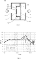
- FIG. 1 is a structure diagram illustrating an acoustic output device according to some embodiments of the present disclosure.
- An acoustic output device 100 may include an internally hollow housing 110, and an acoustic driver 120 disposed in an internal cavity of the housing 110.
- the acoustic driver 120 may include a diaphragm 121 and a magnetic circuit structure 1220.
- the acoustic driver 120 may also include a voice coil (not shown in FIG. 1 ). The voice coil may be fixed on a side of the diaphragm 121 facing the magnetic circuit structure 1220 and located in a magnetic field formed by the magnetic circuit structure 1220.
- a side of the diaphragm 121 away from the magnetic circuit structure 1220 i.e., the right side of the diaphragm 121 shown in FIG. 1
- a side of the magnetic circuit structure 1220 away from the diaphragm 121 i.e., the left side of the magnetic circuit structure 1220 shown in FIG. 1
- a back side of the acoustic driver 120 i.e., the left side of the magnetic circuit structure 1220 shown in FIG. 1
- a vibration of the diaphragm 121 may cause the acoustic driver 120 to radiate sound outward from the front side and the back side of the acoustic driver 120, respectively.
- the front side of the acoustic driver 120 or the diaphragm 121, and the housing 110 may form a front cavity 111.
- the back side of the acoustic driver 120 and the housing 110 may form a rear cavity 112.
- the front side of the acoustic driver 120 may radiate sound to the front cavity 111, and the back side of the acoustic driver 120 may radiate sound to the rear cavity 112.
- the housing 110 may also include a first sound guide hole 113 and a second sound guide hole 114.
- the first sound guide hole 113 may be in fluid communication with the front cavity 111, and the second sound guide hole 113 may be in fluid communication with the rear cavity 112.
- the sound generated from the front side of the acoustic driver 120 may be propagated to the outside through the first sound guide hole 113, and the sound generated from the back side of the acoustic driver 120 may be propagated to the outside through the second sound guide hole 114.
- the magnetic circuit structure 1220 may include a magnetic guide plate 1221 arranged opposite to the diaphragm.
- the magnetic guide plate 1221 may be provided with at least one sound guide hole 1222 (also be referred to as a pressure relief hole) for guiding and propagating the sound generated by the vibration of the diaphragm 121 from the back side of the acoustic driver 120 to the outside through the rear cavity 112.
- the acoustic output device 100 may form a dual sound source (or a multiple-sound source) that is similar to a dipole structure through the sound radiation from the first sound guide hole 113 and the second sound guide hole 114, and a specific sound field with a certain directionality may be generated.
- the sound generated from the front side of the acoustic driver 120 is directly radiated outward through the first sound guide hole 113 on the front cavity 111, the sound generated from the back side of the acoustic driver 120 needs to first pass through the cavity formed by the diaphragm 121 and the magnetic circuit structure 1220, then pass through the sound guide hole 1222 on the magnetic circuit structure 1220 (e.g., the magnetic guide plate 1221) and the second sound guide hole 114 on the rear cavity 112, and further be radiated to the outside.
- the sound guide hole 1222 on the magnetic circuit structure 1220 e.g., the magnetic guide plate 122
- FIG. 2 is a schematic diagram illustrating a far-field sound leakage of an acoustic driver provided in FIG.1 . As shown in FIG.
- the front cavity 111, the rear cavity 112, and the cavity formed by the diaphragm 121 and the magnetic circuit structure 1220 in the acoustic output device 100 may cause the sound in the front cavity 111 ("front cavity” in FIG. 2 ) and the sound in the rear cavity 112 ("rear cavity” in FIG. 2 ) of the acoustic output device 100 to form a resonant peak in a medium frequency or a medium-high frequency (e.g., 2000 Hz-4000 Hz).
- a medium frequency or a medium-high frequency e.g., 2000 Hz-4000 Hz.
- Attenuation degrees of the frequency response of the front cavity 111 and the rear cavity 112 may be different (the frequency response of the rear cavity 112 may be weakened faster), resulting in a poor frequency response of a dipole-like structure formed by the acoustic output device 100 at a relatively high frequency (e.g., the first sound guide hole 113 and the second sound guide hole 114 radiate sounds with a relatively large amplitude difference).
- the sound leakage of the acoustic output device 100 in the far field is not well suppressed.
- the present disclosure may provide another or more acoustic output devices including at least two acoustic drivers.
- the acoustic output device may be located at least on one side of the head of the user head, close to but not blocking the ear of the use .
- the acoustic output device may be worn on the head of the user (e.g., a non-in-ear open headset worn in a form of glasses, a headband, or other structures), or on other parts of the body of the user (e.g., a neck/shoulder area of the user), or placed near the ear of the user ear by other means (e.g., holding in hands of the user).
- the acoustic output device may include a first acoustic driver, a second acoustic driver, a control circuit, and a housing.
- the first acoustic driver may include a first diaphragm.
- the second acoustic driver may include a second diaphragm.
- the control circuit may be electrically connected to the first acoustic driver and the second acoustic driver, respectively.
- the control circuit may provide a first electrical signal for driving a vibration of the first diaphragm, and a second electrical signal for driving a vibration of the second diaphragm.
- the first diaphragm and the second diaphragm may generate a set of sounds in opposite phases.
- the housing may support the first acoustic driver and the second acoustic driver, wherein the sound generated by the vibration of the first diaphragm may be radiated outward through the first sound guide hole on the housing, and the sound generated by the vibration of the second diaphragm may be radiated outward through the second sound guide hole on the housing.
- the sound generated by the first diaphragm may refer to the sound generated by the front side of the first acoustic driver
- the sound generated by the second diaphragm may refer to the sound generated by the front side of the second acoustic driver.
- the first sound guide hole and the second sound guide hole may be approximately regarded as a dual sound source (e.g., a two-point sound source).
- the sound generated by the first diaphragm and the sound generated by the second diaphragm may both not need to be radiated outward through the magnetic circuit structure of the acoustic driver, which may ensure that the acoustic impedance of the front side of the first acoustic driver is basically the same as the acoustic impedance of the front side of the second acoustic driver.
- the sounds emitted from the first sound guide hole and the second sound guide hole may form an effective dual sound source.
- the frequency response of the first acoustic driver may be the same as or similar to the frequency response of the second acoustic driver in a medium-high frequency band.
- the phase of the first electrical signal for driving the vibration of the first diaphragm is opposite to the phase of the second electrical signal for driving the vibration of the second diaphragm, in the far field (e.g., a position far away from the ear of the user), especially in the medium-high frequency band (e.g., 200 Hz-20 kHz), the sound emitted from the first sound guide hole may offset the sound emitted from the second sound guide hole, which may suppress the sound leakage of the acoustic output device to a certain extent. At the same time, the sound generated by the acoustic output device can be prevented from being heard by others near the user.
- the medium-high frequency band e.g. 200 Hz-20 kHz
- the first acoustic driver and the second acoustic driver may be the same or similar acoustic drivers, so that the amplitude frequency response of the first acoustic driver and the amplitude frequency response of the second acoustic driver in a full frequency band are the same or similar.
- the first acoustic driver and the second acoustic driver may be different acoustic drivers.
- the frequency response of the first acoustic driver and the frequency response of the second acoustic driver may be the same or similar in a medium-high frequency band, while the frequency response of the first acoustic driver and the frequency response of the second acoustic driver may be different in a low frequency band.
- Detailed descriptions of the first acoustic driver and the second acoustic driver may refer to FIG. 3 , FIG. 4 , and descriptions thereof.
- the sound generated by the vibration of the first/second diaphragm may also refer to the sound generated by the back side of the first/second acoustic driver, and it is only necessary to ensure that acoustic impedances between the two acoustic drivers and their corresponding sound guide holes are the same or basically the same.
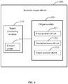
- FIG. 3 is a block diagram illustrating an exemplary acoustic output device according to some embodiments of the present disclosure.
- an acoustic output device 300 may include a signal processing module 310 and an output module 320.
- the signal processing module 310 may include a control circuit 311.
- the control circuit 311 may be configured to receive an initial acoustic signal, process the initial acoustic signal, and output a corresponding control signal (also referred to as an audio signal), that is, control the generation of a sound wave and the output of a signal.
- the initial acoustic signal may be an electrical signal converted from the sound of external environment by one or more acoustoelectric conversion devices (e.g., a microphone).
- the acoustic output device 300 may include one or more air or bone guided microphones to collect and convert air vibration or any other perceptible mechanical vibrations into electrical signals, and send the electrical signals to the signal processing module 310.
- the acoustic output device may obtain the initial acoustic signal from one or more signal sources.
- the one or more signal sources may be an internal device (e.g., a memory) of the acoustic output device 300, or an external device of the acoustic output device 300.
- the external device may send a signal containing sound information to the acoustic output device 300 in a wired or wireless manner.
- the output module 320 may include one or more electroacoustic conversion devices (i.e., an acoustic driver).
- the acoustic driver in the output module 320 may be electrically connected with the control circuit 311, and configured to generate sound waves according to the control signal.
- the output module 320 may include a first acoustic driver 321 and a second acoustic driver 322.
- the control signal may include a first electrical signal and a second electrical signal, wherein the first electrical signal may be configured to drive the first acoustic driver 321 to make sound, and the second electrical signal may be configured to drive the second acoustic driver 322 to make sound.
- the first acoustic driver 321 may include a first diaphragm and a first magnetic circuit structure
- the second acoustic driver 322 may include a second diaphragm and a second magnetic circuit structure, wherein the first electric signal may drive a vibration of the first diaphragm, and the second electric signal may drive a vibration of the second diaphragm.
- a phase of the first electric signal and a phase of the second electric signal may be opposite.
- the first diaphragm is driven by the first electric signal to vibrate toward the first magnetic circuit structure
- the second diaphragm is driven by the second electrical signal to vibrate away from the second magnetic circuit structure, such that a phase of the sound generated by the first acoustic driver 321 and a phase of the sound generated by the second acoustic driver 322 may be opposite.
- the first acoustic driver 321 and the second acoustic driver 322 may be electrically connected with the control circuit 311 in opposite polarities, respectively. At this time, the first acoustic driver 321 and the second acoustic driver 322 may be connected in parallel and then connected in series with the control circuit 311. For ease of understanding, the opposite polarities may be described as that a positive pole of the first acoustic driver 321 is connected to an output terminal of the control circuit 311, and a negative pole of the second acoustic driver 322 is connected to the output terminal of the control circuit 311.
- the control circuit 311 may generate a set of audio signals.
- the two acoustic drivers may obtain the first electrical signal and the second electrical signal in opposite polarities, respectively.
- the first acoustic driver 321 and the second acoustic driver 322 may be electrically connected with the signal processing module 310 in a same polarity, respectively.
- the signal processing module 310 may output two sets of audio signals in opposite phases.
- a phase inverter circuit may be added between the control circuit 311 and the first acoustic driver 321 or the second acoustic driver 322.
- the phase inverter circuit may be configured to invert the phase of the audio signal with 180°.
- the audio signal generated by the control circuit 311 may be transmitted to the first acoustic driver 321 and the second acoustic driver 322 in positive phase and negative phase, respectively, so that the two acoustic drivers may obtain the first electrical signal and the second electrical signal in opposite polarities, respectively.
- the acoustic output device 300 may also include a housing.
- the housing may support the first acoustic driver 321 and the second acoustic driver 322.
- the housing may be provided with at least one first sound guide hole and at least one second sound guide hole.
- the sound generated by the vibration of the first diaphragm of the first acoustic driver 321 may be radiated outward through the at least one first sound guide hole.
- the sound generated by the vibration of the second diaphragm of the second acoustic driver 322 may be radiated outward through the at least one second sound guide hole.
- the first sound guide hole and the second sound guide hole may be located in a front cavity of the first acoustic driver 321 and a front cavity of the second acoustic driver 322, respectively.
- the first sound guide hole and the second sound guide hole may be located in a rear cavity of the first acoustic driver 321 and a rear cavity of the second acoustic driver 322, respectively.
- the sound emitted from the first sound guide hole and the sound emitted from the second sound guide hole may offset with each other in the far field (e.g., far from the ear of the user), which may reduce the sound leakage volume of the acoustic output device 300.
- An acoustic driver may be an element that can receive an electrical signal and convert the electrical signal into a sound signal for output.
- the first acoustic driver 321 and/or the second acoustic driver 322 may be a speaker that can output air guided sound waves.
- the first acoustic driver 321 and/or the second acoustic driver 322 may also be a speaker that can output sound waves conducted by a solid medium (e.g., bone conduction sound waves).
- types of acoustic drivers may include a low frequency (e.g., 20 Hz to 200 Hz) acoustic driver, a medium-high frequency (e.g., 200 Hz to 8 kHz) acoustic driver, a high frequency (e.g., greater than 8 kHz) acoustic driver, or any combination thereof.
- the low frequency and the high frequency may only represent an approximate range of frequencies.
- the frequency division point may be any value within an audible range of human ears, such as 500 Hz, 600 Hz, 700 Hz, 800 Hz, 1000 Hz, etc.
- the acoustic driver may include but is not limited to a moving coil driver, a moving iron driver, a piezoelectric driver, an electrostatic driver, a magneto strictive driver, or the like.
- the first acoustic driver 321 and the second acoustic driver 322 may be same acoustic drivers.
- the first acoustic driver 321 and the second acoustic driver 322 may be acoustic drivers of a same model manufactured by a same manufacturer.
- the first acoustic driver 321 and the second acoustic driver 322 may both be medium-high frequency speakers and may have the same amplitude frequency response in the medium-high frequency band.
- the phases of the first electrical signal and the second electrical signal are opposite, the phases of sounds output from the front sides (or the back sides) of the first acoustic driver 321 and the second acoustic driver 322 may be opposite.
- the sound waves generated from the front sides of the first acoustic driver 321 and the second acoustic driver 322 may be radiated to the outside through the corresponding sound guide holes (e.g., the first sound guide hole and the second sound guide hole), and the sound emitted from the corresponding sound guide holes may be regarded as two point sound sources.
- the two point sound sources may generate medium-high frequency sound in opposite phases, which may inversely offset in the far field, and the sound leakage volume in the medium-high frequency band in the far field may be reduced.
- a physical size of the low frequency acoustic driver may be greater than a physical size of the medium-high frequency acoustic driver. It should be understood that an area of a diaphragm of the low frequency acoustic driver may be larger than an area of a diaphragm of the medium-high frequency acoustic driver. It should be noted that the area of the diaphragm may refer to an effective area of the diaphragm during a vibration process. In other embodiments, an output effect of the low frequency acoustic driver in the low frequency may be ensured by changing a diaphragm structure or a diaphragm material.
- the first acoustic driver 321 and the second acoustic driver 322 may be different acoustic drivers.
- the first acoustic driver 321 and the second acoustic driver 322 may have different amplitude frequency responses in the low frequency band, while the first acoustic driver 321 and the second acoustic driver 322 may have the same or similar amplitude frequency responses in the medium-high frequency band.
- a dual sound source with opposite phases in the medium-high frequency band may be constructed to reduce the sound leakage volume in the medium-high frequency band in the far field.
- the amplitude frequency responses of the first acoustic driver 321 and the second acoustic driver 322 are different or have a large difference, driven by the first electrical signal and the second electrical signal, although the phases of the low-frequency sounds generated by the first acoustic driver 321 and the second acoustic driver 322 are opposite, the intensities of the low-frequency sounds generated by the first acoustic driver 321 and the second acoustic driver 322 are quite different. Therefore, the effect of sound offset may be weak, and loud low-frequency near-field sound can still be heard by the user's ear.
- the signal processing module 310 may include a filter/filter group (also be referred to as a filter system).
- the filter/filter group may adaptively change the first electrical signal and/or the second electrical signal input into the first acoustic driver 321 and/or the second acoustic driver 322 according to an actual situation. For example, the filter/filter group may filter out a low frequency signal in the first electrical signal, so that the first acoustic driver 321 can only output a sound in the medium-high frequency band.
- the acoustic output effect of the acoustic output device in the low frequency band may be improved.
- the output module 320 may also include a third acoustic driver 323.
- the third acoustic driver 323 may include a third diaphragm.
- the third diaphragm may be driven by a third electrical signal to vibrate.
- the third acoustic driver 323 may be a low frequency acoustic driver.
- the filter/filter group may filter out a medium-high frequency signal in the control signal, and send a remaining low frequency signal to the third acoustic driver 323.
- the third acoustic driver 323 may only output a sound in the low frequency band, which may improve the acoustic output effect of the acoustic output device 300 in the low frequency band.
- the third acoustic driver 323 may output a sound having the same phase or a specific phase difference (e.g., an absolute value of the phase difference is less than 90°) with the sound generated by the first acoustic driver 321 or the second acoustic driver 322.
- the low frequency or medium-high frequency sound output by the third acoustic driver 323 may be used as a compensation for the low frequency or medium-high frequency sound heard by the user, making it easier for the user to hear the sound emitted by the acoustic output device in the high noise environment.
- control circuit 311 may also include a switch for controlling a switching state of the filter/filter group, the phase inverter circuit, and/or the acoustic driver.
- the switch may control the acoustic output device to adjust the sound according to different scenarios. For example, in the high noise environment, the sound leakage in the far field may not be easily heard by others near the user.
- the first acoustic driver 321 and the second acoustic driver 322 are both medium-high frequency acoustic drivers, the phases of the first electrical signal and the second electrical signal may be adjusted to be the same by closing the phase inverter circuit.
- the first acoustic driver 321 and the second acoustic driver 322 may generate and output sound with the same phase in the medium-high frequency band, and the output volume of the acoustic output device in the medium-high frequency band may be increased.
- the filter/filter group electrically connected with the low frequency acoustic driver may be turned off, so that the low frequency acoustic driver can also generate sound waves in the medium-high frequency band according to the control signal, and the volume of the medium-high frequency band output by the acoustic output device can be increased.
- a frequency division may be performed on the control signal (e.g., the third electrical signal) for controlling the third acoustic driver 323 by controlling the filter/filter group of the third acoustic driver 323.
- the signal processing module 310 may adjust the phase of the low frequency signal obtained after the frequency division, so that a phase of the low-frequency sound wave generated by the third acoustic driver 323 is opposite to the low frequency noise in the external noise, to realize an effect of actively reducing low frequency noise.
- the medium-high frequency signal obtained after the frequency division may make the third acoustic driver 323 generate a medium-high frequency sound.
- the medium-high frequency sound may have the same phase as or have a small phase difference (e.g., not greater than 90°) with the medium-high frequency sound generated by the first acoustic driver 321 and the second acoustic driver 322, to achieve an effect of noise reduction in the low frequency band and an effect of increasing the output volume in the high frequency band at the same time.
- a small phase difference e.g., not greater than 90°
- a corresponding control signal may be processed in the signal processing module 310, so that the sound wave output by each acoustic driver contains a specific frequency component, respectively.
- a structure or an arrangement of each component in the output module 320 may be set and optimized, so that the sound wave output by the each acoustic driver contains a specific frequency component, respectively.
- several filters/filter groups may be set to process the control signal to output signals containing different frequency components, and then output the signals to a corresponding output module 320 for sound output.
- the filters/ filter groups may include but are not limited to an analog filter, a digital filter, a passive filter, an active filter, or the like.
- a low frequency may refer to a frequency band approximately between 20 Hz and 200 Hz
- a medium-high frequency may refer to a frequency band approximately between 200 Hz and 20 kHz
- the medium-high frequency may refer to a frequency band approximately between 400 Hz and10 kHz. More preferably, the medium-high frequency may refer to a frequency band approximately between 600 Hz and 8 kHz.
- the frequency band may also be divided into a low frequency band, a medium-low frequency band, a medium frequency band, a medium-high frequency band, a high frequency band, or the like.
- the low frequency may refer to a frequency band approximately between 20 Hz and 80 Hz
- the medium-low frequency may refer to a frequency band approximately between 80 Hz and 160 Hz
- the medium frequency may refer to a frequency band approximately between 160 Hz and 2 kHz
- the medium-high frequency may refer to a frequency band approximately between 2 kHz and 8 kHz
- the high frequency may refer to a frequency band approximately between 8 kHz and 20 kHz.
- More descriptions of the specific structure and the distribution of the first acoustic driver 321, the second acoustic driver 322, the third acoustic driver 323, and their components may refer to FIG. 1 , FIG. 4 , and descriptions thereof.
- FIG. 4 is a structure diagram illustrating an exemplary acoustic output device according to some embodiments of the present disclosure.
- the acoustic output device 400 may include an internally hollow housing 410, a first acoustic driver 420 and a second acoustic driver 430 disposed in the housing 410.
- the acoustic output device 400 may be worn on the body of the user (e.g., the head, the neck, or the upper torso of the human body) through the housing 410.
- the housing 410, the first acoustic driver 420, and the second acoustic driver 430 may be close to but not block an ear canal, so that the ear of the user remains open, and the user can not only hear a sound output by the acoustic output device 400, but also hear a sound of an external environment.
- the acoustic output device 400 may be arranged around or partially around the ear of the user and may transmit the sound through an air conduction or a bone conduction.
- the housing 410 may be used to be worn on the body of the user body and may support an acoustic driver (e.g., the first acoustic driver 420 and the second acoustic driver 430).
- the housing 410 may be a closed housing structure with a hollow interior, and the acoustic driver may be located inside the housing 410.
- the acoustic output device 400 may be combined with a product such as glasses, a headset, a head-mounted display device, an AR/VR helmet, or the like.
- the housing 410 may be fixed in the vicinity of the ear of the user by means of hanging or clamping.
- the housing 410 may be provided with a hook.
- a shape of the hook may match a shape of an auricle, so that the acoustic output device 400 can be independently worn on the ear of the user through the hook.
- the acoustic output device 400 which is independently worn on the user may be connected to a signal source (e.g., a computer, a mobile phone, or other mobile devices) in a wired or wireless (e.g., Bluetooth) manner.
- a signal source e.g., a computer, a mobile phone, or other mobile devices
- a wired or wireless e.g., Bluetooth
- the acoustic output devices 400 at the left ear and the right ear may include a first output device and a second output device, wherein the first output device may be connected to and communicated with the signal source, and the second output device may be connected to the first output device in a wireless manner.
- the first output device and the second output device may realize a synchronization of audio playback via one or more synchronization signals.
- the manner of wireless connection may include but is not limited to, a Bluetooth, a local area network, a wide area network, a wireless personal area network, a near field communication, or the like, or any combination thereof.
- the housing 410 may be a housing structure having a shape adapted to a human ear, e.g., an annulus shape, an oval shape, a polygonal shape (regular or irregular), a U-shape, a V-shape, a semi-circular shape, so that the housing 410 can be directly attached to the ear of the user.
- the housing 410 may also include one or more fixed structures.
- the fixing structure may include an ear hook, a head beam, or an elastic band, so that the acoustic output device 400 can be fixed on the user better, and prevent the acoustic output device 400 from falling during the user use the acoustic output device 400.
- the elastic band may be a headband.
- the headband may be configured to be worn around a head area.
- the elastic band may be a neckband configured to be worn around a neck/shoulder area.
- the elastic band may be a continuous band and may be elastically stretched to fit over the head of the user.
- the elastic band may also exert pressure on the head of the user so that the acoustic output device 100 can be firmly fixed on a specific position of the head of the user.
- the elastic band may be a discontinuous band.
- the elastic band may include a rigid portion and a flexible portion, wherein the rigid portion may be made of a rigid material (e.g., a plastic or a metal).
- the rigid portion may be fixed with the housing 410 of the acoustic output device 400 via a physical connection (e.g., a snap connection, a screw connection, etc.).
- the flexible portion may be made of an elastic material (e.g., a cloth, a composite material, or/and a neoprene).
- the acoustic driver (e.g., the first acoustic driver 420 and the second acoustic driver 430) may include a diaphragm and a magnetic circuit structure. More description of the structures of the first acoustic driver 420 and the second acoustic driver 430 may refer to FIG. 1 of the present disclosure and descriptions thereof, and details are not described herein.
- the control signal e.g., the first electrical signal and the second electrical signal
- sounds may be emitted from the front side and the back side of the diaphragm, respectively.
- the housing 410 may include a first cavity 411 and a second cavity 412, wherein the first cavity 411 may be not in fluid communication with the second cavity 412, that is, a baffle may be provided in the housing 410 to isolate the first cavity 411 from the second cavity 412.
- the housing 410 may include a first housing and a second housing. The first housing may be fixedly connected with the second housing. The first cavity 411 may be arranged inside the first cavity 411, and the second cavity 412 may be arranged inside the second cavity 412. The first acoustic driver 420 may be located in the first cavity 411. A front side of the first acoustic driver 420 and the housing 410 may form a first front cavity 4111.
- a back side of the first acoustic driver 420 and the housing structure 420 may form a first rear cavity 4112.
- the front side of the first acoustic driver 420 may radiate the sound toward the first front cavity 4111.
- the back side of the first acoustic driver 420 may radiate the sound toward the first rear cavity 4112.
- the second acoustic driver 430 may be located in the second cavity 412.
- a front side of the second acoustic driver 430 and the housing 410 may form a second front cavity 4121.
- a back side of the second acoustic driver 430 and the housing 410 may form a second rear cavity 4122.
- the front side of the second acoustic driver 430 may radiate the sound toward the second front cavity 4121.
- the back side of the second acoustic driver 430 may radiate the sound toward the second rear cavity 4122.
- the first cavity 411 may be the same as the second cavity 412.
- the first acoustic driver 420 and the second acoustic driver 430 may be disposed in the first cavity 411 and the second cavity 412, respectively, in a same manner, so that the first front cavity 4111 is the same as the second front cavity 4121, and the first rear cavity 4112 is the same as the second rear cavity 4122, which may make the acoustic impedances of the front side or the back side of the first acoustic driver 420 and the second acoustic driver 430 are the same.
- first cavity 411 and the second cavity 412 may be different.
- the impedances of the front side or the back side of the first acoustic driver 420 and the second acoustic driver 430 may be the same by changing a size and/or a length of the cavity or increasing a damping.
- one or more first sound guide holes 413 may be provided on a side wall of the housing 410 where the first front cavity 4111 is located.
- the one or more first sound guide holes 413 may be in fluid communication with the first front cavity 4111.
- the sound output from the front side of the first acoustic driver 420 may be radiated to the outside of the acoustic output device 400 through the one or more first sound guide holes 413.
- One or more second sound guide holes 414 may be provided on a side wall of the housing 410 where the second front cavity 4121 is located.
- the one or more second sound guide holes 414 may be in fluid communication with the second front cavity 4121.
- the sound output from the front side of the second acoustic driver 430 may be radiated to the outside of the acoustic output device 400 through the one or more second sound guide holes 414.
- the first sound guide hole 413 and the second sound guide hole 414 may be located on opposite side walls of the housing 410.
- the first sound guide hole 413 may be located on a side wall of the housing 410 facing the ear of the user, and the second sound guide hole 414 may be located on a side wall of the housing 410 away from the ear of the user.
- the first sound guide hole 413 may be located on a side wall of the housing 410 opposite to the front side of the first acoustic driver 420
- the second sound guide hole 414 may be located on a side wall of the housing 410 opposite to the front side of the second acoustic driver 430.
- the acoustic output device 400 may not include the first front cavity 4111, the second front cavity 4121, the first rear cavity 4112, or the second rear cavity 4122.
- the front side of the first acoustic driver 420 and the front side of the second acoustic driver 430 may radiate the sound to the outside directly. That is, the front side of the first acoustic driver 420 and the housing 410 may not form the first front cavity 4111, and the front side of the second acoustic driver 430 and the housing 410 may not form the second front cavity 4121.
- the first rear cavity 4112 and the second rear cavity 4122 may be sealed, or may be provided with one or more tuning holes (also referred to as pressure relief holes, which are not shown in FIG. 4 ) for adjusting an air pressure inside the rear cavity.
- the first acoustic driver 420 and the second acoustic driver 430 may be the same acoustic drivers.
- the signal processing module may control the front side of the first acoustic driver 420 and the front side of the second acoustic driver 430 to generate sounds with a certain phase and amplitude condition (e.g., sounds with a same amplitude and opposite phases, sounds with different amplitudes and opposite phases, etc.) according to the control signal (e.g., the first electrical signal and the second electrical signal).
- the sound generated from the front side of the first acoustic driver 420 may be radiated to the outside of the acoustic output device 400 through the first sound guide hole 413.
- the sound generated from the front side of the second acoustic driver 430 may be radiated to the outside of the acoustic output device 400 through the second sound guide hole 414.
- the first sound guide hole 413 and the second sound guide hole 414 may be equivalent to a dual sound source outputting sounds in opposite phases.
- sounds in opposite phases may be generated through the front sides of the two acoustic drivers, i.e., the front side of the first acoustic driver 420 and the front side of the second acoustic driver 430, and radiated to the outside through the first sound guide hole 413 and the second sound guide hole 414.
- sounds emitted from the first sound guide hole 413 and the second sound guide hole 414 in the acoustic output device 400 may be constructed as an effective dual sound source, i.e., the first sound guide hole 413 and the second sound guide hole 414 may emit sounds in opposite phases more accurately.
- the sound from the first sound guide hole 413 may offset the sound from the second sound guide hole 414 better, which may better suppress the sound leakage of the acoustic output device in the medium-high frequency band to a certain extent.
- the sound generated by the acoustic output device 400 may be prevented from being heard by others near the user, thereby improving the sound leakage reduction effect of the acoustic output device 400.
- the first sound guide hole 413 and the second sound guide hole 414 may also be located on different sides of the housing 410, and the housing 410 may act as a baffle between the two sound sources (e.g., the sound emitted from the first sound guide hole 413 and the sound emitted from the second sound guide hole 414).
- the housing 410 may separate the first sound guide hole 413 and the second sound guide hole 414, so that an acoustic path from the first sound guide hole 413 to the ear canal of the user and an acoustic path from the second sound guide hole 414 to the ear canal of the user are different.
- a sound path difference between the sound emitted from the first sound guide hole 413 to an ear of the user and a sound emitted from the second sound guide hole 414 to the ear of the user i.e., a difference between a distance of the sound emitted from the first sound guide hole 413 to the ear canal of the user, and a distance of the sound emitted from the second sound guide hole 414 to the ear canal of the user
- a sound path difference between the sound emitted from the first sound guide hole 413 to an ear of the user and a sound emitted from the second sound guide hole 414 to the ear of the user i.e., a difference between a distance of the sound emitted from the first sound guide hole 413 to the ear canal of the user, and a distance of the sound emitted from the second sound guide hole 414 to the ear canal of the user
- the effect of sound offset at the ear of the user may be weakened, thereby increasing the volume of the sound (also be referred to as a near-field sound) heard by the ear of the user, and providing the user with a better listening experience.
- the housing 410 may have little effect on the sound transmitted by the sound guide hole to the environment, far-field sounds generated by the first sound guide hole 413 and the second sound guide hole 414 may still offset with each other well, which may suppress the sound leakage of the acoustic output device 400 to a certain extent, and may prevent the sound generated by the acoustic output device 400 heard by others near the user at the same time. Therefore, by using the above settings, the listening volume of the acoustic output device 400 in the near field may be improved, and the sound leakage volume of the acoustic output device 400 in the far-field may be reduced.
- the sound output by the first acoustic driver 420 from the first sound guide hole 413 and the sound output by the second acoustic driver 430 from the second sound guide hole 414 may satisfy a specific condition by setting the structures of the first cavity 411 (e.g., the first front cavity 4111 and the first rear cavity 4112) and the second cavity 412 (e.g., the second front cavity 4121 and the second rear cavity 4122).
- first cavity 411 e.g., the first front cavity 4111 and the first rear cavity 4112
- the second cavity 412 e.g., the second front cavity 4121 and the second rear cavity 4122
- sizes and/or lengths of the first front cavity 4111 and the second front cavity 4112 may be designed, so that a set of sounds with a specific phase relationship (e.g., opposite or approximately opposite phases) can be output from the first sound guide hole 413 and the second sound guide hole 414, which may effectively solve the problems of low listening volume in the near-field and a sound leakage in the far-field of the acoustic output device 400.
- a specific phase relationship e.g., opposite or approximately opposite phases
- the positions of the first cavity 411 and the second cavity 412 in the embodiments of the present disclosure in FIG. 4 are not limited to be vertically arranged up and down relative to the position of the ear of the user as shown in FIG. 4 , but can also be obliquely set up and down relative to the position of the ear of the user, laterally and horizontally set relative to the position of the ear of the user, laterally and obliquely set relative to the position of the ear of the user, or the like.
- the positions of the first cavity 411, the second cavity 412, the first acoustic driver 420, and the second acoustic driver 430 may be adaptively adjusted according to an actual situation, which is not limited herein.
- FIG. 5 is a frequency response curve diagram of an acoustic output device when two acoustic drivers of the acoustic output device are the same according to some embodiments of the present disclosure.
- the acoustic output device is provided with two identical first acoustic drivers 420 ("speaker A” shown in FIG. 5 ) and second acoustic drivers 430 ("speaker B" shown in FIG. 5 )
- amplitude frequency responses of the first acoustic driver 420 and the second acoustic driver 430 in the medium-high frequency band (e.g., 200 Hz-8 kHz) and the high frequency band (e.g., greater than 8 kHz) may be approximately the same.
- the first acoustic driver 420 and the second acoustic driver 430 may emit sounds in opposite phases through the first sound guide hole 413 and the second sound guide hole 414 under the driving of the first electrical signal and the second electrical signal in opposite phases, so that the acoustic output device can construct an effective dual sound source in the medium-high frequency band and the high frequency band.
- a difference between amplitude frequency responses of the first acoustic driver and the second acoustic driver in the medium-high frequency band and the high frequency band may be not greater than 6 dB.
- the difference between the amplitude frequency responses of the first acoustic driver and the second acoustic driver in the medium-high frequency band and the high frequency band may be not greater than 5 dB. More preferably, the difference between the amplitude frequency responses of the first acoustic driver and the second acoustic driver in the medium-high frequency band and the high frequency band may be not greater than 4 dB. Further preferably, the difference between the amplitude frequency responses of the first acoustic driver and the second acoustic driver in the medium-high frequency band and the high frequency band may be not greater than 3 dB.
- the medium-high frequency band and the high frequency band may be in a specific frequency band range. The specific frequency band range may be 200 Hz-20 kHz.
- FIG. 6 is a frequency response curve diagram of an acoustic output device when two acoustic drivers of the acoustic output device are different according to some embodiments of the present disclosure. As shown in FIG. 6 , when the acoustic output device is provided with two different first acoustic driver 420 ("speaker A" shown in FIG. 6 ) and second acoustic driver 430 ("speaker B" shown in FIG.
- the amplitude frequency responses of the first acoustic driver 420 and the second acoustic driver 430 in the low frequency band may have a certain difference
- the amplitude frequency responses of the first acoustic driver 420 and the second acoustic driver 430 in the medium-high frequency band and the high frequency band may be approximately the same.
- a difference between the amplitude frequency responses of the first acoustic driver and the second acoustic driver in at least a portion of the low frequency range may be not less than 10 dB, so that output volumes of the two acoustic drivers in the low frequency range have a large difference.
- the difference between the amplitude frequency responses of the first acoustic driver and the second acoustic driver in at least a portion of the low frequency range may be not less than 15 dB. Further preferably, the difference between the amplitude frequency responses of the first acoustic driver and the second acoustic driver in at least a portion of the low frequency range may be not less than 20 dB. In some embodiments, when the user wears the acoustic output device, the acoustic path from the first acoustic driver 420 to the ear of the user may be smaller than the acoustic path from the second acoustic driver 430 to the ear of the user.
- the volume difference between the low-frequency sound emitted by the first acoustic driver 420 and the low-frequency sound emitted by the second acoustic driver 430 at the ear of the user may further be increased.
- the offset degree of the low-frequency sounds may be weakened, and the listening volume of the low-frequency sounds at the ear of the user may be increased.
- the acoustic path from the acoustic driver to the ear of the user may refer to a distance between a diaphragm to the ear of the user, for example, a distance from the first diaphragm of the first acoustic driver 420 to the ear of the user.
- the acoustic path from the acoustic driver to the ear of the user may refer to an acoustic distance from a sound guide hole corresponding to the acoustic driver to the ear of the user, for example, an acoustic distance from the first sound guide hole 413 corresponding to the first acoustic driver 420 to the ear of the user.
- the first acoustic driver 420 and the second acoustic driver 430 may emit sounds in opposite phases and in same or similar amplitudes through the first sound guide hole 413 and the second sound guide hole 414, under the driving of the first electrical signal and the second electrical signal in opposite phases, which may enable the acoustic output device to construct an effective dual sound source in the medium-high frequency band and the high frequency band.
- the difference between the amplitude frequency responses of the first acoustic driver and the second acoustic driver in the medium-high frequency band and the high frequency band may be not greater than 6 dB.
- the difference between the amplitude frequency responses of the first acoustic driver and the second acoustic driver in the medium-high frequency band and the high frequency band may be not greater than 5 dB.
- the difference between the amplitude frequency responses of the first acoustic driver and the second acoustic driver in the medium-high frequency band and the high frequency band may be not greater than 4 dB. Further preferably, the difference between the amplitude frequency responses of the first acoustic driver and the second acoustic driver in the medium-high frequency band and the high frequency band may be not greater than 3 dB. In some embodiments, the medium-high frequency band and the high frequency band may be in a specific frequency band range. The specific frequency band range may be 200 Hz-20 kHz.
- FIG. 7 and FIG. 8 are structure diagrams illustrating an acoustic output device according to some embodiments of the present disclosure.
- the acoustic output device 700 may include a first acoustic driver 720, a second acoustic driver 730, a third acoustic driver 740, and a housing 710.
- the interior of the housing 710 may include a first cavity 711, a second cavity 712, and a third cavity 713 that are not in fluid communication with each other, wherein the first acoustic driver 720 may be located in the first cavity 711, the second acoustic driver 730 may be located in the second cavity 712, and the third acoustic driver 740 may be located in the third cavity 713.
- the front side of the first acoustic driver 720 and the housing 710 may form a first front cavity 7111.
- the back side of the first acoustic driver 720 and the housing 720 may form a first rear cavity 7112.
- the front side of the first acoustic driver 720 may radiate the sound toward the first front cavity 7111.
- the back side of the first acoustic driver 720 may radiate the sound toward the first rear cavity 7112.
- the front side of the second acoustic driver 730 and the housing 710 may form a second front cavity 7121.
- the back side of the second acoustic driver 730 and the housing 710 may form a second rear cavity 7122.
- the front side of the second acoustic driver 730 may radiate the sound toward the second front cavity 7121.
- the back side of the second acoustic driver 730 may radiate the sound toward the second rear cavity 7122.
- the front side of the third acoustic driver 740 and the housing 710 may form a third front cavity 7131.
- the back side of the third acoustic driver 740 and the housing 710 may form a third rear cavity 7132.
- the front side of the third acoustic driver 730 may radiate the sound toward the third front cavity 7131.
- the back side of the third acoustic driver 740 may radiate the sound toward the third rear cavity 7122.
- one or more first sound guide holes 714 may be provided on a side wall of the housing 710 where the first front cavity 7111 is located.
- the one or more first sound guide holes 714 may be in fluid communication with the first front cavity 7111.
- the sound output from the front side of the first acoustic driver 720 may be radiated to the outside of the acoustic output device 700 through the one or more first sound guide holes 714.
- One or more second sound guide holes 715 may be provided on a side wall of the housing 710 where the second front cavity 7121 is located.
- the one or more second sound guide holes 715 may be in fluid communication with the second front cavity 712.
- the sound output from the front side of the second acoustic driver 730 may be radiated to the outside of the acoustic output device 700 through the one or more second sound guide holes 715.
- the first sound guide hole 714 and the second sound guide hole 715 may be located on different side walls of the housing 710.
- the first sound guide hole 714 and the second sound guide hole 715 may be located on adjacent side walls of the housing 710, respectively.
- first sound guide hole 714 and the second sound guide hole 715 may be located on opposite side walls of the housing 710, respectively.
- One or more third sound guide holes 716 may be provided on a side wall of the housing 710 where the third front cavity 7131 is located.
- the one or more third sound guide holes 715 may be in fluid communication with the third front cavity 7131.
- the sound output from the front side of the third acoustic driver 740 may be radiated to the outside of the acoustic output device 700 through the one or more third sound guide holes 716.
- One or more fourth sound guide holes 717 may be provided on a side wall of the housing 710 where the third rear cavity 7132 is located.
- the one or more fourth sound guide holes 717 may be in fluid communication with the fourth rear cavity 7132.
- the sound output from the back side of the third acoustic driver 740 may be radiated to the outside of the acoustic output device 700 through the one or more fourth sound guide holes 717.
- the third sound guide hole 716 and the fourth sound guide hole 717 may be located on different side walls of the housing 710.
- the third sound guide hole 716 and the fourth sound guide hole 717 may be located on adjacent side walls of the housing 710, respectively.
- the third sound guide hole 716 and the fourth sound guide hole 717 may be located on opposite side walls of the housing 710, respectively.
- the first acoustic driver 720 and the second acoustic driver 730 may be medium-high frequency acoustic drivers, and the third acoustic driver 740 may be a low frequency acoustic driver.
- the first acoustic driver 720 and the second acoustic driver 730 may emit sound waves in opposite phases under the control of the first electrical signal and the second electrical signal in opposite phases.
- the third acoustic driver 740 may filter out a middle-high frequency component in the first electrical signal or the second electrical signal through a filter/filter group, and only output a low-frequency sound. Further, the third acoustic driver 730 may output sound waves in opposite phases through the third sound guide hole 716 and the fourth sound guide hole 717.
- the first sound guide holes 714 and the third sound guide holes 716 may face the ear of the user
- the second sound guide hole 715 may face the ear of the user or away from the ear of the user
- the fourth sound guide hole 717 may away from the ear of the user.
- a phase of a sound emitted from one of the third sound guide hole 716 and the fourth sound guide hole 717 which is closer to the ear of the user may be the same as a phase of a sound emitted from the one of the first sound guide hole 714 and the second sound guide hole 715 which is closer to the ear of the user.
- phases of sounds emitted from different sound guide holes close to the ear of the user may be the same, so that the sounds emitted from the different sound guide holes can be superimposed, thereby increasing a listening volume at the ear of the user.
- sound waves emitted from the different sound guide holes e.g., the first sound guide hole 714 and the second sound guide hole 715, the third sound guide hole 716 and the fourth sound guide hole 717) may offset with each other due to their opposite phases, thereby reducing the sound leakage volume of the acoustic output device in the far-field.
- the sound output by the first acoustic driver 720 from the first sound guide hole 714, the sound output by the second acoustic driver 730 from the second acoustic guide hole 715, or the sound output by the third acoustic driver 740 from the third sound guide hole 716 or the fourth sound guide hole 717 may satisfy a certain condition.
- sizes and/or lengths of the first front cavity 4111 and the third front cavity 7131 may be designed, so that a group of sounds in the same phase can be output from the first sound guide hole 413 and the second sound guide hole 414.
- a sound path difference between a sound emitted from the third sound guide hole 716 to the ear of the user and a sound emitted from the fourth sound guide hole 717 to the ear of the user may be greater than a sound path difference between a sound emitted from the first sound guide hole 714 to the ear of the user and a sound emitted from the second sound guide hole 715 to the ear of the user.
- the acoustic output device 700 shown in FIG. 7 and FIG. 8 may not only reduce the sound leakage volume in the medium-high frequency band in the far-field, and improve the listening effect of the sound in the low frequency band, but also can be applied to a high noise environment.
- the phases of the first electrical signal and the second electrical signal may be adjusted to be the same by closing a phase inverter circuit, so that a phase of a medium-high frequency sound output by the first acoustic driver 720 through the first sound guide hole 714 is the same as a phase of a medium-high frequency sound output by the second acoustic driver 730 through the second sound guide hole 715, thereby improving the output volume of the acoustic output device in the medium-high frequency band.
- a filter/filter group electrically connected to the third acoustic driver 730 may be turned off, so that the third acoustic driver 730 can also generate a sound wave in the medium-high frequency band according to the control signal.
- the sound wave may radiate toward or away from the ear of the user through the third sound guide hole 716 and the fourth sound guide hole 717, which may increase the volume of the sound in the medium-high frequency band output by the acoustic output device.
- a frequency division may be performed on a control signal (e.g., the third electrical signal) for controlling the third acoustic driver 740.
- the signal processing module may adjust a phase of a low-frequency signal obtained after the frequency division, so that a low frequency sound wave generated by the third acoustic driver 740 is radiated to the outside through the third sound guide hole 716 and the fourth sound guide hole 717.
- a phase of the sound wave emitted by the third sound guide hole 716 and the fourth sound guide hole 717 radiated to the outside may be opposite to a phase of the low-frequency noise in the external noise, which may achieve an effect of actively reducing the low frequency noise.
- the medium-high frequency signal obtained after the frequency division may make the third acoustic driver 740 generate the medium-high frequency sound.
- the medium-high frequency sound may have the same phase as or have a small phase difference (e.g., not greater than 90°) with the medium-high frequency sound generated by the first acoustic driver 720 and the second acoustic driver 730, to achieve an effect of noise reduction in the low frequency band and an effect of increasing the output volume in the high frequency band at the same time.
- a number of acoustic drivers is not limited to three, but may also be four, five, or the like.
- the number of acoustic drivers and corresponding sound parameters may be adjusted according to an actual need, which is not limited herein.
- the specific structure of the acoustic driver may refer to FIG. 1 of the present disclosure and descriptions thereof.
- the first/second/third acoustic drivers described in FIG. 7 and FIG. 8 may be the same as or similar to the first/second/third acoustic drivers described in FIG. 3 , FIG. 4 and descriptions thereof.
- aspects of the present disclosure may be illustrated and described through several patentable categories or situations, including any new and useful processes, machines, products, or combinations of materials, or any new and useful improvements. Accordingly, all aspects of the present disclosure may be performed entirely by hardware, may be performed entirely by software (including firmware, resident software, microcode, etc.), or may be performed by a combination of hardware and software.
- the above hardware or software can be referred to as "data block”, “module”, “engine”, “unit”, “component” or “system”.
- aspects of the present disclosure may appear as a computer product located in one or more computer-readable media, the product including computer-readable program code.
- the computer storage medium may include a propagation data signal containing a computer program encoding, such as on a baseband or as part of a carrier.
- the propagation signal may have a variety of expressions, including electromagnetic form, optical form, etc., or suitable combinations.
- the computer storage medium may be any computer readable medium other than the computer readable storage medium, which may perform system, devices, or devices to implement system, devices, or devices to implement communication, propagating, or devices, by connecting to an instruction.
- Program encoding on a computer storage medium may be propagated by any suitable medium, including radio, cable, fiber optic cable, RF, or a similar medium, or a combination of the above media.
- Computer program code for carrying out operations for aspects of the present disclosure may be written in any combination of one or more programming languages, including an object oriented programming language such as Java, Scala, Smalltalk, Eiffel, JADE, Emerald, C++, C#, VB. NET, Python, or the like, conventional procedural programming languages, such as the "C" programming language, Visual Basic, Fortran 2003, Perl, COBOL 2002, PHP, ABAP, dynamic programming languages such as Python, Ruby, and Groovy, or other programming languages.
- the program code may be run entirely on the user's computer, or as an independent software package on the user's computer, or partly on the user's computer and partly on a remote computer, or entirely on the remote computer or server.
- the remote computer may be connected to the user's computer through any network form, such as a local area network (LAN) or a wide area network (WAN), or to an external computer (for example, via the Internet), or in a cloud computing environment, or as a service such as a Software as a Service (SaaS).
- LAN local area network
- WAN wide area network
- SaaS Software as a Service
- the numbers expressing quantities of ingredients, properties, and so forth, used to describe and claim certain embodiments of the application are to be understood as being modified in some instances by the term "about,” “approximate,” or “substantially”. Unless otherwise stated, "about,” “approximate,” or “substantially” may indicate ⁇ 20% variation of the value it describes. Accordingly, in some embodiments, the numerical parameters set forth in the description and attached claims are approximations that may vary depending upon the desired properties sought to be obtained by a particular embodiment. In some embodiments, the numerical parameters should consider specified significant digits and adopt ordinary rounding techniques. Notwithstanding that the numerical ranges and parameters configured to illustrate the broad scope of some embodiments of the present disclosure are approximations, the numerical values in specific examples may be as accurate as possible within a practical scope.
Landscapes
- Engineering & Computer Science (AREA)
- Physics & Mathematics (AREA)
- Acoustics & Sound (AREA)
- Signal Processing (AREA)
- Health & Medical Sciences (AREA)
- Otolaryngology (AREA)
- Manufacturing & Machinery (AREA)
- Multimedia (AREA)
- Ophthalmology & Optometry (AREA)
- General Physics & Mathematics (AREA)
- General Health & Medical Sciences (AREA)
- Optics & Photonics (AREA)
- Headphones And Earphones (AREA)
- Details Of Audible-Bandwidth Transducers (AREA)
- Soundproofing, Sound Blocking, And Sound Damping (AREA)
- Obtaining Desirable Characteristics In Audible-Bandwidth Transducers (AREA)
- Audible-Bandwidth Dynamoelectric Transducers Other Than Pickups (AREA)
- Circuit For Audible Band Transducer (AREA)
- Piezo-Electric Transducers For Audible Bands (AREA)
- Pharmaceuticals Containing Other Organic And Inorganic Compounds (AREA)
Applications Claiming Priority (3)
| Application Number | Priority Date | Filing Date | Title |
|---|---|---|---|
| CN201910888762 | 2019-09-19 | ||
| CN201910888067 | 2019-09-19 | ||
| PCT/CN2020/116319 WO2021052485A1 (zh) | 2019-09-19 | 2020-09-18 | 一种声学输出装置 |
Publications (2)
| Publication Number | Publication Date |
|---|---|
| EP4009660A1 true EP4009660A1 (de) | 2022-06-08 |
| EP4009660A4 EP4009660A4 (de) | 2022-10-05 |
Family
ID=74883893
Family Applications (4)
| Application Number | Title | Priority Date | Filing Date |
|---|---|---|---|
| EP20864563.0A Pending EP4009665A4 (de) | 2019-09-19 | 2020-08-04 | Akustikausgabevorrichtung |
| EP20865964.9A Pending EP4009660A4 (de) | 2019-09-19 | 2020-09-18 | Akustikausgabevorrichtung |
| EP20948847.7A Pending EP4109925A4 (de) | 2019-09-19 | 2020-12-29 | Akustische ausgabevorrichtung |
| EP21913245.3A Pending EP4184940A4 (de) | 2019-09-19 | 2021-09-18 | Schallerzeugungsvorrichtung |
Family Applications Before (1)
| Application Number | Title | Priority Date | Filing Date |
|---|---|---|---|
| EP20864563.0A Pending EP4009665A4 (de) | 2019-09-19 | 2020-08-04 | Akustikausgabevorrichtung |
Family Applications After (2)
| Application Number | Title | Priority Date | Filing Date |
|---|---|---|---|
| EP20948847.7A Pending EP4109925A4 (de) | 2019-09-19 | 2020-12-29 | Akustische ausgabevorrichtung |
| EP21913245.3A Pending EP4184940A4 (de) | 2019-09-19 | 2021-09-18 | Schallerzeugungsvorrichtung |
Country Status (13)
| Country | Link |
|---|---|
| US (8) | US11956591B2 (de) |
| EP (4) | EP4009665A4 (de) |
| JP (4) | JP7682551B2 (de) |
| KR (4) | KR102602341B1 (de) |
| CN (5) | CN114175677B (de) |
| AU (2) | AU2020350921B2 (de) |
| BR (1) | BR112023004520A2 (de) |
| CA (2) | CA3153521C (de) |
| CL (2) | CL2022000657A1 (de) |
| CO (2) | CO2022003143A2 (de) |
| MX (2) | MX2022003327A (de) |
| PE (2) | PE20220598A1 (de) |
| WO (4) | WO2021052046A1 (de) |
Families Citing this family (43)
| Publication number | Priority date | Publication date | Assignee | Title |
|---|---|---|---|---|
| US8665174B2 (en) | 2011-01-13 | 2014-03-04 | The Boeing Company | Triangular phased array antenna subarray |
| CA3153521C (en) * | 2019-09-19 | 2024-02-13 | Shenzhen Shokz Co., Ltd. | Acoustic output apparatus |
| PE20221251A1 (es) | 2019-12-13 | 2022-08-15 | Shenzhen Shokz Co Ltd | Dispositivo de emision acustica |
| CN113163297B (zh) * | 2021-04-29 | 2023-10-27 | 歌尔科技有限公司 | 音频装置以及智能头戴设备 |
| CN113225643B (zh) * | 2021-04-29 | 2022-11-22 | 歌尔光学科技有限公司 | 一种音频装置及智能头戴设备 |
| CN114466097A (zh) * | 2021-08-10 | 2022-05-10 | 荣耀终端有限公司 | 防漏音的移动终端及移动终端的声音输出方法 |
| CN113747326A (zh) * | 2021-09-29 | 2021-12-03 | 歌尔光学科技有限公司 | 发声装置及其控制方法、以及控制装置 |
| EP4432694A4 (de) * | 2021-11-09 | 2025-12-24 | Ntt Inc | Akustische signalausgabevorrichtung |
| JP7786466B2 (ja) | 2021-11-09 | 2025-12-16 | Ntt株式会社 | 音響信号出力装置 |
| WO2023084574A1 (ja) * | 2021-11-09 | 2023-05-19 | 日本電信電話株式会社 | 音響信号出力装置 |
| CN118176743A (zh) * | 2021-11-09 | 2024-06-11 | 日本电信电话株式会社 | 音响信号输出装置 |
| CN113993031B (zh) * | 2021-11-10 | 2023-07-14 | 歌尔科技有限公司 | 发声装置、发声装置的校准方法及发声单元 |
| CN114125115B (zh) * | 2021-11-16 | 2023-09-15 | 维沃移动通信有限公司 | 电声模组和电子设备 |
| CN114143640B (zh) * | 2021-11-30 | 2023-07-21 | 歌尔科技有限公司 | 一种头戴设备及其远场消声方法、装置及系统 |
| CN117561723A (zh) * | 2022-02-25 | 2024-02-13 | 深圳市韶音科技有限公司 | 一种声学输出装置 |
| CN116709118A (zh) * | 2022-02-25 | 2023-09-05 | 深圳市韶音科技有限公司 | 一种声学输出装置 |
| CN118947135A (zh) * | 2022-03-31 | 2024-11-12 | 日本电信电话株式会社 | 音响信号输出装置 |
| US12225363B2 (en) * | 2022-06-13 | 2025-02-11 | Htc Corporation | Speaker module and wearable device |
| CN115103264B (zh) * | 2022-06-20 | 2025-07-25 | 维沃移动通信有限公司 | 发声模组和电子设备 |
| CN118525527A (zh) * | 2022-06-24 | 2024-08-20 | 深圳市韶音科技有限公司 | 一种声学装置 |
| WO2024034321A1 (ja) * | 2022-08-10 | 2024-02-15 | 株式会社オーディオテクニカ | イヤホン |
| CN115460307B (zh) * | 2022-08-29 | 2024-07-23 | 湖北星纪魅族科技有限公司 | 电子设备及电子设备发声方法 |
| JP7785641B2 (ja) * | 2022-09-14 | 2025-12-15 | Ntt株式会社 | 音響信号出力装置 |
| CN116939424A (zh) * | 2022-10-28 | 2023-10-24 | 深圳市韶音科技有限公司 | 一种开放式耳机 |
| CN115580805A (zh) * | 2022-10-28 | 2023-01-06 | 深圳市珑为科技有限公司 | 开放式耳机 |
| WO2024088224A1 (zh) * | 2022-10-28 | 2024-05-02 | 深圳市韶音科技有限公司 | 一种耳机 |
| CN115623398B (zh) * | 2022-10-31 | 2026-04-10 | 维沃移动通信有限公司 | 电子设备 |
| CN115767374B (zh) * | 2022-11-09 | 2025-08-05 | 歌尔股份有限公司 | 发声装置和穿戴设备 |
| CN118338209A (zh) * | 2022-11-21 | 2024-07-12 | 深圳市韶音科技有限公司 | 一种声学输出装置 |
| CN115604637B (zh) * | 2022-12-15 | 2023-03-03 | 苏州敏芯微电子技术股份有限公司 | Mems麦克风和电子设备 |
| CN116055941A (zh) * | 2023-01-09 | 2023-05-02 | 聆感智能科技(深圳)有限公司 | 音频输出模块和开放式耳机 |
| CN119769105A (zh) * | 2023-03-24 | 2025-04-04 | 深圳市韶音科技有限公司 | 一种耳机 |
| CN119895895A (zh) * | 2023-03-24 | 2025-04-25 | 深圳市韶音科技有限公司 | 一种声学输出装置 |
| CN116560087A (zh) * | 2023-03-31 | 2023-08-08 | 湖北星纪魅族科技有限公司 | 头戴设备 |
| US12302051B2 (en) * | 2023-04-26 | 2025-05-13 | Logitech Europe S.A. | Low profile acoustic module |
| CN116546372A (zh) * | 2023-05-10 | 2023-08-04 | 地球山(苏州)微电子科技有限公司 | 一种耳机发声方法、装置及设备 |
| EP4611394A3 (de) * | 2023-05-12 | 2025-10-08 | Shenzhen Shokz Co., Ltd. | Verschleisskomponente und ohrhörer |
| WO2025002435A1 (zh) * | 2023-06-30 | 2025-01-02 | 深圳市大十未来科技有限公司 | 音频装置 |
| KR20250069761A (ko) * | 2023-11-10 | 2025-05-20 | 엘지디스플레이 주식회사 | 음향 장치 및 이를 포함하는 운송 장치 |
| KR20250166314A (ko) * | 2023-12-04 | 2025-11-27 | 썬전 샥 컴퍼니, 리미티드 | 음향출력장치 |
| DE212023000471U1 (de) * | 2023-12-15 | 2026-03-12 | Shenzhen Shokz Co., Ltd. | Akustische Ausgabevorrichtung |
| KR20260005932A (ko) * | 2024-05-27 | 2026-01-12 | 썬전 샥 컴퍼니, 리미티드 | 소리출력장치 |
| CN121397407A (zh) * | 2024-07-17 | 2026-01-23 | 深圳市韶音科技有限公司 | 一种开放式耳机 |
Family Cites Families (118)
| Publication number | Priority date | Publication date | Assignee | Title |
|---|---|---|---|---|
| JPS52156526U (de) | 1976-05-22 | 1977-11-28 | ||
| IT1086464B (it) | 1977-09-06 | 1985-05-28 | Selmin Sas | Metodo e dispositivi per l'irradiazione omnidirezionale di onde acustiche |
| JPS599491Y2 (ja) | 1979-04-18 | 1984-03-26 | 三菱電機株式会社 | スピ−カ |
| JPS58191598A (ja) | 1982-05-06 | 1983-11-08 | Matsushita Electric Ind Co Ltd | スピ−カシステム |
| JPS58194499A (ja) | 1982-05-07 | 1983-11-12 | Matsushita Electric Ind Co Ltd | スピ−カシステム |
| JPS5912685A (ja) | 1982-07-12 | 1984-01-23 | Matsushita Electric Ind Co Ltd | スピ−カ装置 |
| JPS619988U (ja) | 1984-06-21 | 1986-01-21 | 三菱電機株式会社 | バスレフ型スピ−カボツクス |
| US4899390A (en) | 1986-09-19 | 1990-02-06 | Matsushita Electric Industrial Co., Ltd. | Thin speaker having an enclosure within an open portion and a closed portion |
| JP2568675Y2 (ja) * | 1988-07-22 | 1998-04-15 | ヤマハ株式会社 | 音響装置 |
| JPH02133090U (de) * | 1989-04-05 | 1990-11-05 | ||
| EP0410352B1 (de) * | 1989-07-24 | 1994-09-28 | Matsushita Electric Industrial Co., Ltd. | Lautsprechersystem |
| JPH0348997U (de) * | 1989-09-20 | 1991-05-13 | ||
| JP2786285B2 (ja) * | 1989-12-25 | 1998-08-13 | カルソニック株式会社 | アクティブ・ノイズ・キャンセラー |
| JPH03274892A (ja) * | 1990-03-23 | 1991-12-05 | Sharp Corp | 電気音響変換器 |
| US5147986A (en) * | 1990-12-03 | 1992-09-15 | Tandy Corporation | Subwoofer speaker system |
| KR940002165A (ko) * | 1992-07-31 | 1994-02-16 | 제럴드 켄트 화이트 | 초순도의 탄화규소와 이것으로 만든 고온의 반도체 처리 장치 |
| JP3281181B2 (ja) * | 1994-06-27 | 2002-05-13 | 松下電器産業株式会社 | 音場再生用スピーカシステム |
| JP3153113B2 (ja) * | 1995-09-28 | 2001-04-03 | 富士通テン株式会社 | ヘッドホン装置 |
| JP3625233B2 (ja) | 1995-12-26 | 2005-03-02 | フオスター電機株式会社 | スピーカユニット及びスピーカシステム |
| JP3815513B2 (ja) * | 1996-08-19 | 2006-08-30 | ソニー株式会社 | イヤホン |
| US5815589A (en) * | 1997-02-18 | 1998-09-29 | Wainwright; Charles E. | Push-pull transmission line loudspeaker |
| JPH1132388A (ja) | 1997-07-10 | 1999-02-02 | Sony Corp | スピーカ装置 |
| JPH11220789A (ja) * | 1998-01-30 | 1999-08-10 | Sony Corp | 電気音響変換装置 |
| JP2000023285A (ja) | 1998-07-01 | 2000-01-21 | Sony Corp | スピーカ及びスピーカ装置 |
| JP2000023280A (ja) | 1998-07-07 | 2000-01-21 | Sony Corp | スピーカ装置 |
| JP2000041292A (ja) | 1998-07-23 | 2000-02-08 | Sony Corp | スピーカ装置 |
| US6169811B1 (en) | 1999-03-02 | 2001-01-02 | American Technology Corporation | Bandpass loudspeaker system |
| JP3742963B2 (ja) | 1999-07-02 | 2006-02-08 | 株式会社ケンウッド | スピーカ装置、および音響再生方法 |
| US6650758B1 (en) * | 1999-12-23 | 2003-11-18 | Nortel Networks Limited | Adaptive dual port loudspeaker implementation for reducing lateral transmission |
| US7103193B2 (en) * | 2000-09-15 | 2006-09-05 | American Technology Corporation | Bandpass woofer enclosure with multiple acoustic fibers |
| US6729726B2 (en) * | 2001-10-06 | 2004-05-04 | Stryker Corporation | Eyewear for hands-free communication |
| US7499555B1 (en) * | 2002-12-02 | 2009-03-03 | Plantronics, Inc. | Personal communication method and apparatus with acoustic stray field cancellation |
| JP4235803B2 (ja) | 2003-04-14 | 2009-03-11 | 日本ビクター株式会社 | スピーカ・システム |
| JP4079827B2 (ja) * | 2003-05-14 | 2008-04-23 | 富士通テン株式会社 | スピーカ装置 |
| JP3790528B2 (ja) | 2003-11-17 | 2006-06-28 | ヤマハリビングテック株式会社 | スピーカシステム |
| US7346315B2 (en) * | 2004-03-30 | 2008-03-18 | Motorola Inc | Handheld device loudspeaker system |
| JP2005311986A (ja) | 2004-04-26 | 2005-11-04 | Berutekku:Kk | スピーカ装置 |
| CA2579556A1 (en) * | 2004-09-07 | 2006-03-16 | Temco Japan Co., Ltd. | Spectacle type communication device |
| KR20070045776A (ko) | 2005-10-28 | 2007-05-02 | 주식회사 현대오토넷 | 크기가 조절되는 인클로저를 갖는 차량용 스피커 시스템 |
| KR100757462B1 (ko) * | 2006-07-14 | 2007-09-11 | 삼성전자주식회사 | 이어폰 |
| JP2008135864A (ja) | 2006-11-27 | 2008-06-12 | Matsushita Electric Works Ltd | 通話装置 |
| US8565463B2 (en) * | 2007-06-12 | 2013-10-22 | Panasonic Corporation | Loudspeaker system |
| JP4905280B2 (ja) | 2007-07-23 | 2012-03-28 | 船井電機株式会社 | ヘッドホンシステム |
| JP4431623B2 (ja) * | 2008-08-22 | 2010-03-17 | 浩一郎 秋元 | スピーカー及びスピーカーシステム |
| JP4341851B1 (ja) | 2008-08-26 | 2009-10-14 | 重幸 黒川 | スピーカ装置 |
| CN101511048B (zh) * | 2009-03-16 | 2012-09-05 | 歌尔声学股份有限公司 | 具有新型振动系统的电声转换器及其振动系统的制造方法 |
| JP5399158B2 (ja) * | 2009-07-27 | 2014-01-29 | 有限会社ジョイ創建 | 二重バッフルを有するスピーカー装置 |
| CN201616895U (zh) * | 2010-02-08 | 2010-10-27 | 华为终端有限公司 | 一种音腔及电子设备 |
| US8553910B1 (en) * | 2011-11-17 | 2013-10-08 | Jianchun Dong | Wearable computing device with behind-ear bone-conduction speaker |
| US11540057B2 (en) * | 2011-12-23 | 2022-12-27 | Shenzhen Shokz Co., Ltd. | Bone conduction speaker and compound vibration device thereof |
| FR2982110B3 (fr) * | 2012-01-10 | 2014-03-14 | Samsung Electronics Co Ltd | Dispositif de lunettes pour visionner une image d'affichage |
| US8971561B2 (en) * | 2012-06-20 | 2015-03-03 | Apple Inc. | Earphone having a controlled acoustic leak port |
| CN103108268B (zh) * | 2013-02-07 | 2016-08-24 | 歌尔声学股份有限公司 | 扬声器模组及其使用该扬声器模组的电子装置 |
| TWI469652B (zh) | 2013-02-08 | 2015-01-11 | Cotron Corp | 耳機 |
| CN103209377B (zh) * | 2013-03-19 | 2016-02-17 | 歌尔声学股份有限公司 | 多功能扬声器 |
| CN103260117A (zh) * | 2013-05-08 | 2013-08-21 | 歌尔声学股份有限公司 | 一种低音扬声器及其应用该低音扬声器的电子装置 |
| CN203301726U (zh) * | 2013-05-08 | 2013-11-20 | 歌尔声学股份有限公司 | 一种低音扬声器及其应用该低音扬声器的电子装置 |
| CN103297904B (zh) * | 2013-05-18 | 2015-09-02 | 歌尔声学股份有限公司 | 一种双振膜扬声器模组 |
| JP6137942B2 (ja) | 2013-05-31 | 2017-05-31 | フォスター電機株式会社 | スピーカシステム |
| US9883280B2 (en) | 2013-08-12 | 2018-01-30 | Sony Corporation | Headphone and acoustic characteristic adjusting method |
| CN203523010U (zh) | 2013-10-10 | 2014-04-02 | 深圳雷柏科技股份有限公司 | 一种辐射倒相式音箱 |
| CN203720476U (zh) * | 2013-11-08 | 2014-07-16 | 深圳市广百思科技有限公司 | 一种蓝牙太阳镜 |
| JP2015103825A (ja) | 2013-11-21 | 2015-06-04 | オンキヨー株式会社 | スピーカーシステム |
| WO2020220719A1 (zh) * | 2019-04-30 | 2020-11-05 | 深圳市韶音科技有限公司 | 一种声学输出装置 |
| CN106470371B (zh) | 2014-01-06 | 2018-02-27 | 深圳市韶音科技有限公司 | 一种能够抑制漏音的骨传导扬声器 |
| CN104540076B (zh) * | 2014-11-20 | 2018-09-07 | 歌尔股份有限公司 | 扬声器模组 |
| CN104540080B (zh) * | 2014-12-26 | 2018-05-01 | 歌尔股份有限公司 | 扬声器模组 |
| CN204465855U (zh) * | 2015-02-13 | 2015-07-08 | 瑞声光电科技(常州)有限公司 | 扬声器 |
| CN104754454B (zh) * | 2015-03-25 | 2019-03-26 | 歌尔股份有限公司 | 扬声器模组 |
| CN204733358U (zh) * | 2015-07-01 | 2015-10-28 | 歌尔声学股份有限公司 | 微型扬声器 |
| JPWO2017038017A1 (ja) * | 2015-09-01 | 2018-06-14 | パナソニックIpマネジメント株式会社 | スピーカ装置 |
| US10506332B2 (en) * | 2015-09-15 | 2019-12-10 | Goertek Inc. | Loudspeaker module |
| JP6563327B2 (ja) | 2015-12-17 | 2019-08-21 | 株式会社オーディオテクニカ | イヤホン |
| CN205283805U (zh) | 2015-12-31 | 2016-06-01 | 歌尔声学股份有限公司 | 扬声器模组 |
| US9794676B2 (en) * | 2016-01-12 | 2017-10-17 | Bose Corporation | Headphone |
| US10051357B2 (en) * | 2016-01-28 | 2018-08-14 | Bose Corporation | Pressure equalization in earphones |
| JP6793300B2 (ja) * | 2016-02-10 | 2020-12-02 | パナソニックIpマネジメント株式会社 | 車両近接報知装置 |
| DE102016103477A1 (de) * | 2016-02-26 | 2017-08-31 | USound GmbH | Audiosystem mit strahlformenden Lautsprechern sowie Brille mit einem derartigen Audiosystem |
| US9838787B1 (en) * | 2016-06-06 | 2017-12-05 | Bose Corporation | Acoustic device |
| US10015586B2 (en) * | 2016-07-20 | 2018-07-03 | AAC Technologies Pte. Ltd. | Speaker box and method for manufacturing same |
| CN205847592U (zh) * | 2016-07-21 | 2016-12-28 | 瑞声科技(新加坡)有限公司 | 扬声器 |
| US9881600B1 (en) * | 2016-07-29 | 2018-01-30 | Bose Corporation | Acoustically open headphone with active noise reduction |
| US10257608B2 (en) | 2016-09-23 | 2019-04-09 | Apple Inc. | Subwoofer with multi-lobe magnet |
| US10397681B2 (en) * | 2016-12-11 | 2019-08-27 | Base Corporation | Acoustic transducer |
| JP2020502840A (ja) | 2016-12-21 | 2020-01-23 | ソニー株式会社 | ヘッドホン装置 |
| EP3568996B1 (de) | 2017-01-12 | 2021-05-12 | SeeScan, Inc. | Magnetfeldunterdrückende audiolautsprecher zur verwendung mit lokalisierern für unterirdische versorgungsleitungen oder anderen vorrichtungen |
| AU2018243565B2 (en) * | 2017-03-30 | 2023-03-16 | Magic Leap, Inc. | Non-blocking dual driver earphones |
| CN206674192U (zh) * | 2017-04-13 | 2017-11-24 | 瑞声科技(新加坡)有限公司 | 微型扬声器 |
| CN207070324U (zh) * | 2017-05-31 | 2018-03-02 | 歌尔股份有限公司 | 扬声器模组以及电子设备 |
| JP6866808B2 (ja) | 2017-09-06 | 2021-04-28 | 株式会社Jvcケンウッド | イヤホン |
| CN207665190U (zh) * | 2017-12-25 | 2018-07-27 | 歌尔科技有限公司 | 扬声器模组及电子设备 |
| CN207677986U (zh) * | 2017-12-29 | 2018-07-31 | 歌尔科技有限公司 | 一种扬声器模组 |
| JP2019121898A (ja) | 2018-01-04 | 2019-07-22 | オンキヨー株式会社 | スピーカー装置 |
| EP3744110B1 (de) | 2018-01-24 | 2025-05-28 | Harman Becker Automotive Systems GmbH | Kopfhöreranordnungen zur erzeugung von natürlichen direktionalen pinna-cues |
| WO2019151988A1 (en) * | 2018-01-30 | 2019-08-08 | Hewlett-Packard Development Company, L.P. | Self-cooling headsets |
| US10555071B2 (en) * | 2018-01-31 | 2020-02-04 | Bose Corporation | Eyeglass headphones |
| US10390143B1 (en) * | 2018-02-15 | 2019-08-20 | Bose Corporation | Electro-acoustic transducer for open audio device |
| JP2019145963A (ja) | 2018-02-19 | 2019-08-29 | オンキヨー株式会社 | イヤホン |
| JP2019145965A (ja) * | 2018-02-19 | 2019-08-29 | オンキヨー株式会社 | イヤホン |
| US10674244B2 (en) * | 2018-02-21 | 2020-06-02 | Bose Corporation | Audio device |
| US10516929B2 (en) * | 2018-03-06 | 2019-12-24 | Bose Corporation | Audio device |
| US10904667B1 (en) * | 2018-03-19 | 2021-01-26 | Amazon Technologies, Inc. | Compact audio module for head-mounted wearable device |
| CN108718430B (zh) * | 2018-04-17 | 2020-05-29 | 歌尔股份有限公司 | 半入耳式耳机 |
| CN109143580B (zh) * | 2018-08-04 | 2021-09-10 | 瑞声科技(新加坡)有限公司 | 一种增强现实眼镜 |
| US10609465B1 (en) * | 2018-10-04 | 2020-03-31 | Bose Corporation | Acoustic device |
| CN208806980U (zh) | 2018-11-09 | 2019-04-30 | 苏州市信天游光电材料有限公司 | 一种防尘防静电的喇叭网罩 |
| US10812896B2 (en) * | 2019-03-21 | 2020-10-20 | Facebook Technologies, Llc | High compliance microspeakers for vibration mitigation in a personal audio device |
| CN209572154U (zh) | 2019-04-10 | 2019-11-01 | 南京咩咩达智能科技有限公司 | 小型平面振膜扬声器及耳机 |
| US11234071B2 (en) | 2019-05-09 | 2022-01-25 | Bose Corporation | Acoustic device |
| CN110568633A (zh) | 2019-08-14 | 2019-12-13 | 歌尔股份有限公司 | 一种智能头戴设备 |
| CN110572745B (zh) * | 2019-08-14 | 2021-07-13 | 歌尔股份有限公司 | 一种智能头戴设备 |
| CN110554520B (zh) | 2019-08-14 | 2020-11-20 | 歌尔股份有限公司 | 一种智能头戴设备 |
| US11122351B2 (en) * | 2019-08-28 | 2021-09-14 | Bose Corporation | Open audio device |
| US11706552B2 (en) | 2019-09-02 | 2023-07-18 | Bose Corporation | Open audio device |
| CA3153521C (en) * | 2019-09-19 | 2024-02-13 | Shenzhen Shokz Co., Ltd. | Acoustic output apparatus |
| CN110830867B (zh) * | 2019-11-01 | 2021-09-17 | 歌尔股份有限公司 | 一种智能头戴设备 |
| CN110933548A (zh) * | 2019-11-22 | 2020-03-27 | 歌尔股份有限公司 | 一种智能头戴设备 |
| EP4088485A1 (de) * | 2020-01-10 | 2022-11-16 | WÖLFL, Genaro | Wandlerfestlegungen für kopf- und ohrhörer |
-
2020
- 2020-08-04 CA CA3153521A patent/CA3153521C/en active Active
- 2020-08-04 JP JP2022517900A patent/JP7682551B2/ja active Active
- 2020-08-04 PE PE2022000409A patent/PE20220598A1/es unknown
- 2020-08-04 KR KR1020227012834A patent/KR102602341B1/ko active Active
- 2020-08-04 CN CN202080053884.0A patent/CN114175677B/zh active Active
- 2020-08-04 AU AU2020350921A patent/AU2020350921B2/en active Active
- 2020-08-04 WO PCT/CN2020/106759 patent/WO2021052046A1/zh not_active Ceased
- 2020-08-04 MX MX2022003327A patent/MX2022003327A/es unknown
- 2020-08-04 EP EP20864563.0A patent/EP4009665A4/de active Pending
- 2020-09-18 PE PE2022000408A patent/PE20220631A1/es unknown
- 2020-09-18 EP EP20865964.9A patent/EP4009660A4/de active Pending
- 2020-09-18 JP JP2022517898A patent/JP7528199B2/ja active Active
- 2020-09-18 CA CA3153093A patent/CA3153093C/en active Active
- 2020-09-18 MX MX2022003326A patent/MX2022003326A/es unknown
- 2020-09-18 AU AU2020349994A patent/AU2020349994B2/en active Active
- 2020-09-18 CN CN202080053883.6A patent/CN114175673B/zh active Active
- 2020-09-18 WO PCT/CN2020/116319 patent/WO2021052485A1/zh not_active Ceased
- 2020-09-18 KR KR1020227012878A patent/KR102602344B1/ko active Active
- 2020-12-29 WO PCT/CN2020/140815 patent/WO2022027915A1/zh not_active Ceased
- 2020-12-29 CN CN202080065942.1A patent/CN114424585A/zh active Pending
- 2020-12-29 JP JP2022563185A patent/JP7600262B2/ja active Active
- 2020-12-29 KR KR1020227038228A patent/KR20220164011A/ko active Pending
- 2020-12-29 EP EP20948847.7A patent/EP4109925A4/de active Pending
-
2021
- 2021-09-18 EP EP21913245.3A patent/EP4184940A4/de active Pending
- 2021-09-18 WO PCT/CN2021/119308 patent/WO2022142500A1/zh not_active Ceased
- 2021-09-18 JP JP2023521777A patent/JP7618029B2/ja active Active
- 2021-09-18 CN CN202111101809.XA patent/CN114697800A/zh active Pending
- 2021-09-18 CN CN202180006890.5A patent/CN114982252B/zh active Active
- 2021-09-18 KR KR1020237010782A patent/KR102746649B1/ko active Active
- 2021-09-18 BR BR112023004520A patent/BR112023004520A2/pt unknown
-
2022
- 2022-02-24 US US17/652,483 patent/US11956591B2/en active Active
- 2022-02-24 US US17/652,480 patent/US12047737B2/en active Active
- 2022-03-17 CL CL2022000657A patent/CL2022000657A1/es unknown
- 2022-03-18 CL CL2022000669A patent/CL2022000669A1/es unknown
- 2022-03-18 CO CONC2022/0003143A patent/CO2022003143A2/es unknown
- 2022-03-18 CO CONC2022/0003130A patent/CO2022003130A2/es unknown
- 2022-09-14 US US17/932,288 patent/US12108208B2/en active Active
-
2023
- 2023-02-07 US US18/165,346 patent/US12225347B2/en active Active
-
2024
- 2024-04-06 US US18/628,711 patent/US20240251202A1/en active Pending
- 2024-07-08 US US18/766,574 patent/US20240365055A1/en active Pending
- 2024-08-30 US US18/820,351 patent/US20240422475A1/en active Pending
-
2025
- 2025-02-07 US US19/047,680 patent/US20250184661A1/en active Pending
Also Published As
Similar Documents
| Publication | Publication Date | Title |
|---|---|---|
| US11956591B2 (en) | Acoustic output device | |
| US11671738B2 (en) | Acoustic output apparatus | |
| US12289592B2 (en) | Acoustic output apparatus | |
| KR20230043940A (ko) | 보청장치들 | |
| HK40069050A (en) | Acoustic output device | |
| RU2790965C1 (ru) | Акустическое выходное устройство | |
| RU2796796C1 (ru) | Акустическое выходное устройство | |
| RU2800623C1 (ru) | Слуховой аппарат | |
| HK40069048A (en) | Acoustic output device | |
| BR112022004399B1 (pt) | Dispositivo de saída acústica |
Legal Events
| Date | Code | Title | Description |
|---|---|---|---|
| STAA | Information on the status of an ep patent application or granted ep patent |
Free format text: STATUS: THE INTERNATIONAL PUBLICATION HAS BEEN MADE |
|
| PUAI | Public reference made under article 153(3) epc to a published international application that has entered the european phase |
Free format text: ORIGINAL CODE: 0009012 |
|
| STAA | Information on the status of an ep patent application or granted ep patent |
Free format text: STATUS: REQUEST FOR EXAMINATION WAS MADE |
|
| 17P | Request for examination filed |
Effective date: 20220301 |
|
| AK | Designated contracting states |
Kind code of ref document: A1 Designated state(s): AL AT BE BG CH CY CZ DE DK EE ES FI FR GB GR HR HU IE IS IT LI LT LU LV MC MK MT NL NO PL PT RO RS SE SI SK SM TR |
|
| REG | Reference to a national code |
Ref country code: HK Ref legal event code: DE Ref document number: 40069050 Country of ref document: HK |
|
| A4 | Supplementary search report drawn up and despatched |
Effective date: 20220905 |
|
| RIC1 | Information provided on ipc code assigned before grant |
Ipc: H04R 1/34 20060101ALI20220830BHEP Ipc: H04R 3/12 20060101ALI20220830BHEP Ipc: H04R 1/40 20060101ALI20220830BHEP Ipc: H04R 1/28 20060101ALI20220830BHEP Ipc: H04R 1/24 20060101ALI20220830BHEP Ipc: H04R 1/10 20060101AFI20220830BHEP |
|
| DAV | Request for validation of the european patent (deleted) | ||
| DAX | Request for extension of the european patent (deleted) | ||
| STAA | Information on the status of an ep patent application or granted ep patent |
Free format text: STATUS: EXAMINATION IS IN PROGRESS |
|
| 17Q | First examination report despatched |
Effective date: 20240402 |