EP4009732B1 - Verfahren und vorrichtung zur unterstützung von benutzergerät-netzwerk-relais-kommunikation in einem drahtlosen kommunikationssystem - Google Patents
Verfahren und vorrichtung zur unterstützung von benutzergerät-netzwerk-relais-kommunikation in einem drahtlosen kommunikationssystem Download PDFInfo
- Publication number
- EP4009732B1 EP4009732B1 EP21209494.0A EP21209494A EP4009732B1 EP 4009732 B1 EP4009732 B1 EP 4009732B1 EP 21209494 A EP21209494 A EP 21209494A EP 4009732 B1 EP4009732 B1 EP 4009732B1
- Authority
- EP
- European Patent Office
- Prior art keywords
- relay
- rrc
- remote
- message
- network node
- Prior art date
- Legal status (The legal status is an assumption and is not a legal conclusion. Google has not performed a legal analysis and makes no representation as to the accuracy of the status listed.)
- Active
Links
Images





Classifications
-
- H—ELECTRICITY
- H04—ELECTRIC COMMUNICATION TECHNIQUE
- H04W—WIRELESS COMMUNICATION NETWORKS
- H04W76/00—Connection management
- H04W76/10—Connection setup
- H04W76/12—Setup of transport tunnels
-
- H—ELECTRICITY
- H04—ELECTRIC COMMUNICATION TECHNIQUE
- H04W—WIRELESS COMMUNICATION NETWORKS
- H04W40/00—Communication routing or communication path finding
- H04W40/02—Communication route or path selection, e.g. power-based or shortest path routing
- H04W40/22—Communication route or path selection, e.g. power-based or shortest path routing using selective relaying for reaching a BTS [Base Transceiver Station] or an access point
-
- H—ELECTRICITY
- H04—ELECTRIC COMMUNICATION TECHNIQUE
- H04W—WIRELESS COMMUNICATION NETWORKS
- H04W76/00—Connection management
- H04W76/10—Connection setup
- H04W76/14—Direct-mode setup
-
- H—ELECTRICITY
- H04—ELECTRIC COMMUNICATION TECHNIQUE
- H04W—WIRELESS COMMUNICATION NETWORKS
- H04W76/00—Connection management
- H04W76/10—Connection setup
- H04W76/11—Allocation or use of connection identifiers
-
- H—ELECTRICITY
- H04—ELECTRIC COMMUNICATION TECHNIQUE
- H04W—WIRELESS COMMUNICATION NETWORKS
- H04W76/00—Connection management
- H04W76/10—Connection setup
- H04W76/18—Management of setup rejection or failure
-
- H—ELECTRICITY
- H04—ELECTRIC COMMUNICATION TECHNIQUE
- H04W—WIRELESS COMMUNICATION NETWORKS
- H04W76/00—Connection management
- H04W76/10—Connection setup
- H04W76/19—Connection re-establishment
-
- H—ELECTRICITY
- H04—ELECTRIC COMMUNICATION TECHNIQUE
- H04W—WIRELESS COMMUNICATION NETWORKS
- H04W76/00—Connection management
- H04W76/20—Manipulation of established connections
- H04W76/27—Transitions between radio resource control [RRC] states
-
- H—ELECTRICITY
- H04—ELECTRIC COMMUNICATION TECHNIQUE
- H04W—WIRELESS COMMUNICATION NETWORKS
- H04W8/00—Network data management
- H04W8/005—Discovery of network devices, e.g. terminals
-
- H—ELECTRICITY
- H04—ELECTRIC COMMUNICATION TECHNIQUE
- H04W—WIRELESS COMMUNICATION NETWORKS
- H04W88/00—Devices specially adapted for wireless communication networks, e.g. terminals, base stations or access point devices
- H04W88/02—Terminal devices
-
- H—ELECTRICITY
- H04—ELECTRIC COMMUNICATION TECHNIQUE
- H04W—WIRELESS COMMUNICATION NETWORKS
- H04W88/00—Devices specially adapted for wireless communication networks, e.g. terminals, base stations or access point devices
- H04W88/02—Terminal devices
- H04W88/04—Terminal devices adapted for relaying to or from another terminal or user
Definitions
- This disclosure generally relates to wireless communication networks, and more particularly, to a method and apparatus for supporting UE-to-network relay communication in a wireless communication system.
- IP Internet Protocol
- An exemplary network structure is an Evolved Universal Terrestrial Radio Access Network (E-UTRAN).
- E-UTRAN Evolved Universal Terrestrial Radio Access Network
- the E-UTRAN system can provide high data throughput in order to realize the above-noted voice over IP and multimedia services.
- a new radio technology for the next generation e.g., 5G
- 5G next generation
- changes to the current body of 3GPP standard are currently being submitted and considered to evolve and finalize the 3GPP standard.
- 3GPP document R2-1912566 discloses identification PC5-S as well as identification on PC5 RRC and RRC procedures.
- EP 3 637 940 A1 discloses a path switching method and related apparatus.
- the method includes the remote UE establishing a PC5 connection with a first relay UE for a relay communication with a first network node.
- the method also includes the remote UE performing a Radio Resource Control (RRC) connection establishment procedure with the first network node via the first relay UE.
- RRC Radio Resource Control
- the method may further include the remote UE transmitting a first RRC message to a second network node via a second relay UE for requesting RRC connection re-establishment, wherein the first RRC message includes a first Cell Radio Network Temporary Identifier (C-RNTI) of the remote UE.
- the method may include the remote UE receiving a second RRC message from the second network via the second relay UE for re-establishing a RRC connection between the second network node and the remote UE, wherein the second RRC message includes a second C-RNTI of the remote UE.
- Wireless communication systems are widely deployed to provide various types of communication such as voice, data, and so on. These systems may be based on code division multiple access (CDMA), time division multiple access (TDMA), orthogonal frequency division multiple access (OFDMA), 3GPP LTE (Long Term Evolution) wireless access, 3GPP LTE-A or LTE-Advanced (Long Term Evolution Advanced), 3GPP2 UMB (Ultra Mobile Broadband), WiMax, 3GPP NR (New Radio), or some other modulation techniques.
- CDMA code division multiple access
- TDMA time division multiple access
- OFDMA orthogonal frequency division multiple access
- 3GPP LTE Long Term Evolution
- 3GPP LTE-A or LTE-Advanced Long Term Evolution Advanced
- 3GPP2 UMB User Mobile Broadband
- WiMax Wireless Broadband
- 3GPP NR New Radio
- the exemplary wireless communication systems and devices described below may be designed to support one or more standards such as the standard offered by a consortium named “3rd Generation Partnership Project” referred to herein as 3GPP, including: TS 38.331 V16.2.0, “NR; Radio Resource Control (RRC) protocol specification (Release 16) "; 3GPP TS38.321 V16.2.1, “NR Medium Access Control (MAC) protocol specification (Release 16) “; 3GPP TR 38.836 V0.2.0, “Study on NR sidelink relay; (Release 17) “; and 3GPP TS 23.287 V16.4.0, “Architecture enhancements for 5G System (5GS) to support Vehicle-to-Everything (V2X) services (Release 16) ".
- 5GS 5G System
- V2X Vehicle-to-Everything
- FIG. 1 shows a multiple access wireless communication system according to one embodiment of the invention.
- An access network 100 includes multiple antenna groups, one including 104 and 106, another including 108 and 110, and an additional including 112 and 114. In FIG. 1 , only two antennas are shown for each antenna group, however, more or fewer antennas may be utilized for each antenna group.
- Access terminal 116 is in communication with antennas 112 and 114, where antennas 112 and 114 transmit information to access terminal 116 over forward link 120 and receive information from access terminal 116 over reverse link 118.
- Access terminal (AT) 122 is in communication with antennas 106 and 108, where antennas 106 and 108 transmit information to access terminal (AT) 122 over forward link 126 and receive information from access terminal (AT) 122 over reverse link 124.
- communication links 118, 120, 124 and 126 may use different frequency for communication.
- forward link 120 may use a different frequency then that used by reverse link 118.
- antenna groups each are designed to communicate to access terminals in a sector of the areas covered by access network 100.
- the transmitting antennas of access network 100 may utilize beamforming in order to improve the signal-to-noise ratio of forward links for the different access terminals 116 and 122. Also, an access network using beamforming to transmit to access terminals scattered randomly through its coverage causes less interference to access terminals in neighboring cells than an access network transmitting through a single antenna to all its access terminals.
- An access network may be a fixed station or base station used for communicating with the terminals and may also be referred to as an access point, a Node B, a base station, an enhanced base station, an evolved Node B (eNB), a network node, a network, or some other terminology.
- An access terminal may also be called user equipment (UE), a wireless communication device, terminal, access terminal or some other terminology.
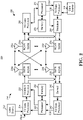
- FIG. 2 is a simplified block diagram of an embodiment of a transmitter system 210 (also known as the access network) and a receiver system 250 (also known as access terminal (AT) or user equipment (UE)) in a MIMO system 200.
- a transmitter system 210 also known as the access network
- a receiver system 250 also known as access terminal (AT) or user equipment (UE)
- traffic data for a number of data streams is provided from a data source 212 to a transmit (TX) data processor 214.
- TX transmit
- each data stream is transmitted over a respective transmit antenna.
- TX data processor 214 formats, codes, and interleaves the traffic data for each data stream based on a particular coding scheme selected for that data stream to provide coded data.
- the coded data for each data stream may be multiplexed with pilot data using OFDM techniques.
- the pilot data is typically a known data pattern that is processed in a known manner and may be used at the receiver system to estimate the channel response.
- the multiplexed pilot and coded data for each data stream is then modulated (i.e., symbol mapped) based on a particular modulation scheme (e.g., BPSK, QPSK, M-PSK, or M-QAM) selected for that data stream to provide modulation symbols.
- a particular modulation scheme e.g., BPSK, QPSK, M-PSK, or M-QAM
- the data rate, coding, and modulation for each data stream may be determined by instructions performed by processor 230.
- TX MIMO processor 220 may further process the modulation symbols (e.g., for OFDM).
- TX MIMO processor 220 then provides N T modulation symbol streams to N T transmitters (TMTR) 222a through 222t.
- TMTR TX MIMO processor 220 applies beamforming weights to the symbols of the data streams and to the antenna from which the symbol is being transmitted.
- Each transmitter 222 receives and processes a respective symbol stream to provide one or more analog signals, and further conditions (e.g., amplifies, filters, and upconverts) the analog signals to provide a modulated signal suitable for transmission over the MIMO channel.
- N T modulated signals from transmitters 222a through 222t are then transmitted from N T antennas 224a through 224t, respectively.
- the transmitted modulated signals are received by N R antennas 252a through 252r and the received signal from each antenna 252 is provided to a respective receiver (RCVR) 254a through 254r.
- Each receiver 254 conditions (e.g., filters, amplifies, and downconverts) a respective received signal, digitizes the conditioned signal to provide samples, and further processes the samples to provide a corresponding "received" symbol stream.
- An RX data processor 260 then receives and processes the N R received symbol streams from N R receivers 254 based on a particular receiver processing technique to provide N T "detected" symbol streams.
- the RX data processor 260 then demodulates, deinterleaves, and decodes each detected symbol stream to recover the traffic data for the data stream.
- the processing by RX data processor 260 is complementary to that performed by TX MIMO processor 220 and TX data processor 214 at transmitter system 210.
- a processor 270 periodically determines which pre-coding matrix to use (discussed below). Processor 270 formulates a reverse link message comprising a matrix index portion and a rank value portion.
- the reverse link message may comprise various types of information regarding the communication link and/or the received data stream.
- the reverse link message is then processed by a TX data processor 238, which also receives traffic data for a number of data streams from a data source 236, modulated by a modulator 280, conditioned by transmitters 254a through 254r, and transmitted back to transmitter system 210.
- the modulated signals from receiver system 250 are received by antennas 224, conditioned by receivers 222, demodulated by a demodulator 240, and processed by a RX data processor 242 to extract the reserve link message transmitted by the receiver system 250.
- Processor 230 determines which pre-coding matrix to use for determining the beamforming weights then processes the extracted message.
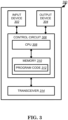
- FIG. 3 shows an alternative simplified functional block diagram of a communication device according to one embodiment of the invention.
- the communication device 300 in a wireless communication system can be utilized for realizing the UEs (or ATs) 116 and 122 in FIG. 1 or the base station (or AN) 100 in FIG. 1 , and the wireless communications system is preferably the NR system.
- the communication device 300 may include an input device 302, an output device 304, a control circuit 306, a central processing unit (CPU) 308, a memory 310, a program code 312, and a transceiver 314.
- the control circuit 306 executes the program code 312 in the memory 310 through the CPU 308, thereby controlling an operation of the communications device 300.
- the communications device 300 can receive signals input by a user through the input device 302, such as a keyboard or keypad, and can output images and sounds through the output device 304, such as a monitor or speakers.
- the transceiver 314 is used to receive and transmit wireless signals, delivering received signals to the control circuit 306, and outputting signals generated by the control circuit 306 wirelessly.
- the communication device 300 in a wireless communication system can also be utilized for realizing the AN 100 in FIG. 1 .
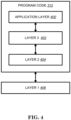
- FIG. 4 is a simplified block diagram of the program code 312 shown in FIG. 3 in accordance with one embodiment of the invention.
- the program code 312 includes an application layer 400, a Layer 3 portion 402, and a Layer 2 portion 404, and is coupled to a Layer 1 portion 406.
- the Layer 3 portion 402 generally performs radio resource control.
- the Layer 2 portion 404 generally performs link control.
- the Layer 1 portion 406 generally performs physical connections.
- 3GPP TS 38.331 introduced the following:
- RRC connection establishment involves SRB1 establishment.
- the procedure is also used to transfer the initial NAS dedicated information/ message from the UE to the network.
- the network applies the procedure e.g.as follows:
- an RRC connection establishment is initiated only in the following cases:
- an RRC connection is initiated only when the conditions specified for V2X sidelink communication in subclause 5.3.3.1a of TS 36.331 [10] are met.
- Upper layers initiate an RRC connection. The interaction with NAS is left to UE implementation.
- the UE initiates the procedure when upper layers request establishment of an RRC connection while the UE is in RRC_IDLE and it has acquired essential system information as described in 5.2.2.1, or for sidelink communication as specified in sub-clause 5.3.3.1a.
- the UE shall ensure having valid and up to date essential system information as specified in clause 5.2.2.2 before initiating this procedure.
- the UE Upon initiation of the procedure, the UE shall:
- the UE shall set the contents of RRCSetupRequest message as follows:
- the UE shall submit the RRCSetupRequest message to lower layers for transmission.
- the UE shall continue cell re-selection related measurements as well as cell re-selection evaluation. If the conditions for cell re-selection are fulfilled, the UE shall perform cell re-selection as specified in 5.3.3.6.
- the UE shall perform the following actions upon reception of the RRCSetup:
- the network initiates the security mode command procedure to a UE in RRC_CONNECTED. Moreover, the network applies the procedure as follows:
- the UE shall:
- the purpose of this procedure is to re-establish the RRC connection.
- a UE in RRC_CONNECTED for which AS security has been activated with SRB2 and at least one DRB setup or, for IAB, SRB2, may initiate the procedure in order to continue the RRC connection.
- the connection re-establishment succeeds if the network is able to find and verify a valid UE context or, if the UE context cannot be retrieved, and the network responds with an RRCSetup according to clause 5.3.3.4.
- the network applies the procedure e.g as follows:
- the UE shall not initiate the procedure but instead moves to RRC_IDLE directly, with release cause 'other'. If AS security has been activated, but SRB2 and at least one DRB or, for IAB, SRB2, are not setup, the UE does not initiate the procedure but instead moves to RRC_IDLE directly, with release cause 'RRC connection failure'.
- the UE initiates the procedure when one of the following conditions is met:
- the UE Upon initiation of the procedure, the UE shall:
- the UE Upon selecting a suitable NR cell, the UE shall:
- the UE Upon selecting an inter-RAT cell, the UE shall:
- the UE shall set the contents of RRCReestablishmentRequest message as follows:
- the UE shall:
- the UE Upon T311 expiry, the UE shall:
- the UE shall:
- the UE shall:
- the RRCSetup message is used to establish SRB1.
- RRCSetup-IEs field descriptions masterCellGroup The network configures only the RLC bearer for the SRB1, mac-CellGroupConfig , physicalCellGroupConfig and spCellConfig. radioBearerConfig Only SRB1 can be configured in RRC setup.
- the RRCSetupComplete message is used to confirm the successful completion of an RRC connection establishment.
- RRCSetupComplete-IEs field descriptions guami-Type This field is used to indicate whether the GUAMI included is native (derived from native 5G-GUTI) or mapped (from EPS, derived from EPS GUTI) as specified in TS 24.501 [23].
- iab-Nodelndication This field is used to indicate that the connection is being established by an IAB-node [2].
- idleMeasAvailable Indication that the UE has idle/inactive measurement report available.
- mobilityState This field indicates the UE mobility state (as defined in TS 38.304 [20], clause 5.2.4.3) just prior to UE going into RRC_CONNECTED state.
- the UE indicates the value of medium and high when being in Medium-mobility and High-mobility states respectively. Otherwise the UE indicates the value normal.
- ng-5G-S-TMSI-Part2 The leftmost 9 bits of 5G-S-TMSI. registeredAMF This field is used to transfer the GUAMI of the AMF where the UE is registered, as provided by upper layers, see TS 23.003 [21].
- selectedPLMN-Identity Index of the PLMN or SNPN selected by the UE from the plmn-IdentityList or npn-IdentityInfoList fields included in SIB1.
- the RRCSetupRequest message is used to request the establishment of an RRC connection.
- RRCSetupRequest-IEs field descriptions establishmentCause Provides the establishment cause for the RRCSetupRequest in accordance with the information received from upper layers.
- gNB is not expected to reject an RRCSetupRequest due to unknown cause value being used by the UE.
- ue-Identity UE identity included to facilitate contention resolution by lower layers.
- InitialUE-Identity field descriptions ng-5G-S- TMSI-Partl The rightmost 39 bits of 5G-S-TMSI. randomValue Integer value in the range 0 to 2 39 - 1.
- the SecurityModeCommand message is used to command the activation of AS security.
- the SecurityModeComplete message is used to confirm the successful completion of a security mode command.
- the RRCReestablishment message is used to re-establish SRB1.
- the RRCReestablishmentComplete message is used to confirm the successful completion of an RRC connection re-establishment.
- the RRCReestablishmentRequest message is used to request the reestablishment of an RRC connection.
- ReestabUE-Identity field descriptions physCellId The Physical Cell Identity of the PCell the UE was connected to prior to the failure.
- RRCReestablishmentRequest-IEs field descriptions reestablishmentCause Indicates the failure cause that triggered the re-establishment procedure.
- gNB is not expected to reject a RRCReestablishmentRequest due to unknown cause value being used by the UE.
- the RRCReconfiguration message is the command to modify an RRC connection. It may convey information for measurement configuration, mobility control, radio resource configuration (including RBs, MAC main configuration and physical channel configuration) and AS security configuration.
- 3GPP TS 38.321 introduced the following:
- the Random Access procedure described in this clause is initiated by a PDCCH order, by the MAC entity itself, or by RRC for the events in accordance with TS 38.300 [2]. There is only one Random Access procedure ongoing at any point in time in a MAC entity.
- the Random Access procedure on an SCell shall only be initiated by a PDCCH order with ra-PreambleIndex different from 0b000000.
- the MAC entity shall, for each Random Access Preamble:
- s_id is the index of the first OFDM symbol of the PRACH occasion (0 ⁇ s_id ⁇ 14)
- t_id is the index of the first slot of the PRACH occasion in a system frame (0 ⁇ t_id ⁇ 80)
- the subcarrier spacing to determine t_id is based on the value of ⁇ specified in clause 5.3.2 in TS 38.211 [8]
- f_id is the index of the PRACH occasion in the frequency domain (0 ⁇ f_id ⁇ 8)
- ul_carrier_id is the UL carrier used for Random Access Preamble transmission (0 for NUL carrier
- the MAC entity shall:
- the MAC entity may stop ra-ResponseWindow (and hence monitoring for Random Access Response(s)) after successful reception of a Random Access Response containing Random Access Preamble identifiers that matches the transmitted PREAMBLE _ INDEX.
- HARQ operation is not applicable to the Random Access Response reception.
- the MAC entity shall:
- the MAC entity Upon completion of the Random Access procedure, the MAC entity shall:
- the target MAC entity Upon successful completion of the Random Access procedure initiated for DAPS handover, the target MAC entity shall:
- 3GPP TR 38.836 introduces the following:
- the UE-to-Network Relay enables coverage extension and power saving for the Remote UE.
- the coverage scenarios considered in this study are the following:
- NR Uu is assumed on the Uu link of the UE-to-Network Relay UE.
- NR sidelink is assumed on PC5 between the Remote UE(s) and the UE-to-Network Relay UE.
- Cross-RAT configuration/control of UE (Remote UE or UE-to-Network Relay UE) is not considered, i.e., eNB/ng-eNB do not control/configure an NR Remote UE and UE-to-Network Relay UE.
- UE-to-Network Relay the study focuses on unicast data traffic between the Remote UE and the NW.
- relaying of unicast data between the Remote UE and the network can occur after a PC5-RRC connection is established between the Relay UE and the Remote UE.
- the Uu RRC state of the relay UE and Remote UE can change when connected via PCS.
- Both Relay UE and Remote UE can perform relay discovery in any RRC state.
- a Remote UE can perform relay discovery while out of Uu coverage.
- a Relay UE must be in RRC_CONNECTED to perform relaying of unicast data.
- both Relay UE and Remote UE can be in RRC_INACTIVE state.
- the requirement of service continuity is only for UE-to-Network Relay, but not for UE-to-UE Relay in this release.
- RAN2 have studied the mobility scenario of "between direct (Uu) path and indirect (via the relay) path" for UE-to-Nework relay.
- RAN2 focus on the mobility scenarios of intra-gNB cases in the study phase, and assume the inter-gNB cases will also be supported.
- potential different parts on Uu interface in details can be studied either in the SI phase or in the WI phase.
- RAN2 deprioritize work specific to the mobility scenario of "between indirect (via a first relay UE) and indirect (via a second relay UE)" for path switching in the SI phase, which can be studied in the WI phase, if needed.
- RAN2 deprioritize the group mobility scenario in the SI phase, which may be discussed in WI phase, if needed.
- Model A and model B discovery model as defined in clause 5.3.1.2 of TS 23.303 [3] are taken as a working assumption for both UE-to-Network Relay and UE-to-UE Relay.
- the protocol stack of discovery message is similar or identical to PC5-S signalling as illustrated in Figure 16.9.2.1-2 of 38.300 [4].
- the detailed definition of a gNB which is not capable of sidelink relay operation can be left for WI phase but at least should include the case that the gNB does not provide SL relay configuration, e.g., no discovery configuration.
- Resource pool to transmit discovery message can be either shared with or separated from resource pool for data transmission.
- remote UE compares the PC5 radio measurements of a relay UE with the threshold which is configured by gNB or preconfigured. Higher layer criteria also need to be considered by remote UE for relay (re-)selection, but details can be left to SA2 to decide. Relay (re-)selection can be triggered by upper layers of remote UE.
- Relay reselection should be triggered if the NR Sidelink signal strength of current Sidelink relay is below a (pre)configured threshold. Also, relay reselection may be triggered if RLF of PC5 link with current relay UE is detected by remote UE.
- relay (re-)selection when remote UE has multiple suitable relay UE candidates which meet all AS-layer & higher layer criteria and remote UE need to select one relay UE by itself, it is up to remote UE implementation to choose one relay UE. This does not exclude gNB involvement in service continuity for UE-to-NW relay scenarios.
- the adaptation layer is placed over RLC sublayer for both CP and UP at the Uu interface between Relay UE and gNB.
- the Uu SDAP/PDCP and RRC are terminated between Remote UE and gNB, while RLC, MAC and PHY are terminated in each link (i.e. the link between Remote UE and UE-to-Network Relay UE and the link between UE-to-Network Relay UE and the gNB).
- the adaptation layer is also supported at the PC5 interface between Remote UE and Relay UE is left to WI phase (assuming down-selection first before studying too much on the detailed PC5 adaptation layer functionalities).
- Remote UE needs to establish its own PDU sessions/DRBs with the network before user plane data transmission.
- PC5-RRC aspects of Rel-16 NR V2X PCS unicast link establishment procedures can be reused to setup a secure unicast link between Remote UE and Relay UE for L2 UE-to-Network relaying before Remote UE establishes a Uu RRC connection with the network via Relay UE.
- the PCS L2 configuration for the transmission between the Remote UE and the UE-to-Network Relay UE can be based on the RLC/MAC configuration defined in specifications.
- Step 1 The Remote and Relay UE perform discovery procedure, and establish PC5-RRC connection using the legacy Rel-16 procedure as a baseline.
- Step 2 The Remote UE sends the first RRC message (i.e., RRCSetupRequest ) for its connection establishment with gNB via the Relay UE, using a default L2 configuration on PC5.
- the gNB responds with an RRCSetup message to Remote UE.
- the RRCSetup delivery to the Remote UE uses the default configuration on PCS. If the relay UE had not started in RRC_CONNECTED, it would need to do its own connection establishment as part of this step.
- the details for Relay UE to forward the RRCSetupRequest / RRCSetup message for Remote UE at this step can be discussed in WI phase.
- Step 3 The gNB and Relay UE perform relaying channel setup procedure over Uu.
- the Relay/Remote UE establishes an RLC channel for relaying of SRB1 towards the Remote UE over PC5. This step prepares the relaying channel for SRB1.
- Step 4 Remote UE SRB1 message (e.g. an RRCSetupComplete message) is sent to the gNB via the Relay UE using SRB1 relaying channel over PC5. Then the Remote UE is RRC connected over Uu.
- RRCSetupComplete message e.g. an RRCSetupComplete message
- Step 5 The Remote UE and gNB establish security following legacy procedure and the security messages are forwarded through the Relay UE.
- Step 6 The gNB sets up additional RLC channels between the gNB and Relay UE for traffic relaying.
- the Relay/Remote UE sets up additional RLC channels between the Remote UE and Relay UE for traffic relaying.
- the gNB sends an RRCReconfiguration to the Remote UE via the Relay UE, to set up the relaying SRB2/DRBs.
- the Remote UE sends an RRCReconfigurationComplete to the gNB via the Relay UE as a response.
- connection establishment procedure for L2 UE-to-Network relay,
- 3GPP TS 23.287 introduced the following:
- the UE To perform unicast mode of V2X communication over PCS reference point, the UE is configured with the related information as described in clause 5.1.2.1.
- Figure 6.3.3.1-1 shows the layer-2 link establishment procedure for unicast mode of V2X communication over PCS reference point.
- the source Layer-2 ID and destination Layer-2 ID used to send the Direct Communication Request message are determined as specified in clauses 5.6.1.1 and 5.6.1.4.
- the destination Layer-2 ID may be broadcast or unicast Layer-2 ID. When unicast Layer-2 ID is used, the Target User Info shall be included in the Direct Communication Request message.
- UE-1 sends the Direct Communication Request message via PC5 broadcast or unicast using the source Layer-2 ID and the destination Layer-2 ID.
- UE-1 When the security protection is enabled, UE-1 sends the following information to the target UE:
- the source Layer-2 ID used for the security establishment procedure is determined as specified in clauses 5.6.1.1 and 5.6.1.4.
- the destination Layer-2 ID is set to the source Layer-2 ID of the received Direct Communication Request message.
- UE-1 Upon receiving the security establishment procedure messages, UE-1 obtains the peer UE's Layer-2 ID for future communication, for signalling and data traffic for this unicast link.
- a Direct Communication Accept message is sent to UE-1 by the target UE(s) that has successfully established security with UE-1:
- the Direct Communication Accept message includes:
- both UEs i.e. the initiating UE and the target UE selected to use link-local IPv6 address, they shall disable the duplicate address detection defined in RFC 4862 [21].
- the V2X layer of the UE that established PC5 unicast link passes the PC5 Link Identifier assigned for the unicast link and the PC5 unicast link related information down to the AS layer.
- the PC5 unicast link related information includes Layer-2 ID information (i.e. source Layer-2 ID and destination Layer-2 ID) and the corresponding PC5 QoS parameters. This enables the AS layer to maintain the PC5 Link Identifier together with the PC5 unicast link related information.
- V2X service data is transmitted over the established unicast link as below:
- the PC5 Link Identifier, and PFI are provided to the AS layer, together with the V2X service data.
- the Layer-2 ID information (i.e. source Layer-2 ID and destination Layer-2 ID) is provided to the AS layer.
- UE-1 sends the V2X service data using the source Layer-2 ID (i.e. UE-1's Layer-2 ID for this unicast link) and the destination Layer-2 ID (i.e. the peer UE's Layer-2 ID for this unicast link).
- source Layer-2 ID i.e. UE-1's Layer-2 ID for this unicast link
- destination Layer-2 ID i.e. the peer UE's Layer-2 ID for this unicast link
- PC5 unicast link is bi-directional, therefore the peer UE of UE-1 can send the V2X service data to UE-1 over the unicast link with UE-1.
- UE-to-Network Relay communication is studied for UE to access network via indirect network communication.
- Rel-16 5G architectural design e.g. flow-based QoS communication over PCS/LTu interface
- a remote UE would access the network (e.g. 5GC) via a relay UE where the remote UE could be out-of-coverage while the relay UE would be in-coverage.
- the remote UE would communicate with the relay UE via PC5 interface (or called sidelink interface) for accessing the network, while the relay UE would communicate with a base station (e.g. gNB) via Uu interface for forwarding traffic between the remote UE and the network.
- PC5 interface or called sidelink interface
- a base station e.g. gNB
- the UE when a UE in RRC_CONNECTED performs a RRC connection reestablishment procedure (due to e.g. handover failure, radio link failure, etc.), the UE transmits a RRC reestablishment request message for re-establishing a RRC connection (e.g. RRCReestablishmentRequest) on a cell to a gNB.
- the UE performs Cell Selection to select the cell (among prepared cells including the original serving cell or a target cell in which the UE is in handover to) before sending the RRC reestablishment request message.
- a Cell Radio Network Temporary Identifier (C-RNTI) of the UE is included.
- the C-RNTI of the UE could be used in the UE's serving cell in which the trigger for the re-establishment occurred.
- the Radio Resource Control (RRC) reestablishment request message could also include a physical cell identity.
- the physical cell identity could be used to identify the serving cell in which the trigger for the re-establishment occurred.
- the physical cell identity could be obtained by the UE from system information broadcasted by the gNB.
- the RRC reestablishment request message could also include a shortMAC-I.
- the shortMAC-I could be calculated by a security key (e.g.
- the K RRCint K RRCint and/or a security algorithm (for integrity protection) used in the serving cell in which the trigger for the re-establishment occurred.
- the security algorithm could be indicated in a security command message (e.g. SecurityModeCommand ) received from the gNB.
- the UE could derive the security key and associate the security key with the security algorithm.
- the security command message could be received before the UE initiates the RRC connection reestablishment procedure.
- the UE obtains the C-RNTI during a random access procedure (as introduced in 3GPP TS 38.321 V16.2.1) performed for a RRC connection establishment procedure.
- the UE sends a RRC setup request message (e.g. RRCSetupRequest ) to a gNB via the random access procedure.
- the UE sends a Msg1 (i.e. random access preamble) to the gNB and then receives a Msg2 (i.e. random access response) from the gNB.
- a temporary C-RNTI and a RAR grant are included.
- the UE uses the RAR grant to send a Msg3 including the RRC setup request message to the gNB. If the UE receives a Msg4 from the gNB based on the temporary C-RNTI and contention resolution of the random access procedure is successful (i.e. the content of Msg4 matches the content of Msg3), then the UE stores the temporary C-RNTI as a C-RNTI. This C-RNTI could be used to construct the content of the RRC reestablishment request message as mentioned above.
- a remote UE communicates with gNB via a relay UE.
- the remote UE cannot obtain such C-RNTI from the gNB since the remote UE does not perform such random access procedure with the gNB.
- provisioning information e.g. C-RNTI, physical cell identity, etc.
- the remote UE needs to establish a RRC connection with the gNB via the relay UE.
- the remote UE could send a RRC setup request message for request of a RRC connection establishment with the gNB to the relay UE, and the relay UE could then forward the RRC setup request message to the gNB.
- the gNB could respond a RRC setup message (e.g. RRCSetup ) for the RRC connection establishment.
- the gNB could send the RRC setup message to the relay UE, and the relay UE could then forward this message to the remote UE.
- the remote UE Upon receipt of the RRC setup message, the remote UE could comply with the configurations included in the RRC setup message (as introduced in3GPP TS 38.331 V16.2.0). Possibly, the RRC setup message could further include a C-RNTI for the remote UE. The remote UE could then send a RRC setup complete message (e.g. RRCSetupComplete ) in response to receipt of the RRC setup message to the relay UE, and the relay UE could then forward the RRC setup complete message to the gNB.
- a RRC setup complete message e.g. RRCSetupComplete
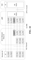
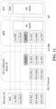
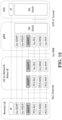
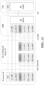
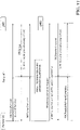
- FIGS. 16 and 17 show two examples of the invention.
- the remote UE may perform relay reselection.
- a new serving cell and a new relay UE may be selected. It is possible the original relay UE may be selected again.
- radio link failure may occur on the Uu radio link between the relay UE and the original gNB (while the PC5 connection between the relay UE and the remote UE is still available).
- the relay UE may perform cell (re)selection.
- the remote UE may initiate a RRC connection reestablishment procedure.
- the remote UE may send a RRC reestablishment request message to the new serving cell or gNB.
- the RRC reestablishment request message could be sent to the new serving cell or gNB directly or via the original relay UE or the new relay UE.
- a RRC re-establishment message (corresponding to the RRC reestablishment request message) from the new serving cell or gNB may include a new C-RNTI (and optionally a new physical cell identity) for the remote UE to use after the RRC connection reestablishment procedure is completed.
- the remote UE could establish a new PC5 connection with the new relay UE before sending the RRC reestablishment request message to the new serving cell or gNB via the new relay UE.
- the PC5 connection may be a PC5 RRC connection or a PC5 unicast link.
- the remote UE could send the RRC setup request message on SRB0.
- the SRB0 could be associated with one PC5 Radio Link Control (RLC) channel.
- RLC Radio Link Control
- the RRC setup request message could be delivered to this PC5 RLC channel for transmission to the relay UE.
- the association between the SRB0 and this PC5 RLC channel could be pre-defined or pre-configured in the remote UE and the relay UE.
- the relay UE could send the RRC setup request message on one Uu RLC channel associated with the PC5 RLC channel on which the RRC setup request message is received.
- the association between this Uu RLC channel and the SRB0 of the remote UE could be pre-defined or pre-configured in the relay UE or configured by the gNB.
- the gNB could send the RRC setup message on the SRB0 of the remote UE.
- the RRC setup message could be delivered to the Uu RLC channel associated with the SRB0 of the remote UE for transmission to the relay UE.
- the relay UE could send the RRC setup message on the PC5 RLC channel associated with this Uu RLC channel for transmission to the remote UE.
- the remote LTE could establish SRB1 in response to reception of the RRC setup message.
- the remote UE could send the RRC setup complete message on the SRB1.
- the SRB1 could be associated with one PC5 RLC channel.
- the RRC setup complete message could be delivered to this PC5 RLC channel for transmission to the relay UE.
- the association between the SRB 1 of the remote UE and this PC5 RLC channel could be pre-defined or pre-configured in the remote UE and the relay UE.
- the relay UE could send the RRC setup complete message to the gNB on one Uu RLC channel associated with the PC5 RLC channel on which the RRC setup complete message is received.
- the association between this Uu RLC channel and the SRB 1 of the remote UE could be pre-defined or pre-configured in the relay UE or configured by the gNB.
- the gNB In order to activate AS security protection for protecting traffic and/or signalling exchanged between the remote UE and the gNB, the gNB sends a security mode command message (e.g. SecurityModeCommand ) to the relay UE, and the relay UE then forwards the security mode command message to the remote UE.
- a security mode command message e.g. SecurityModeCommand
- the remote UE could derive security key and configure lower layers (e.g. PDCP) for applying integrity protection and/or ciphering.
- the remote UE could send a security mode complete message (e.g. SecurityModeComplete ) to the relay UE, and the relay UE could then forward the security mode complete message to the gNB for completing the AS security protection activation.
- the C-RNTI could also be provided for the remote UE in the security mode command message.
- the gNB could send the security mode command message on the SRB1 of the remote UE.
- the security mode command message could be delivered to the Uu RLC channel associated with the SRB 1 of the remote UE for transmission to the relay UE.
- the relay UE could send the security mode command message on the PC5 RLC channel associated with this Uu RLC channel for transmission to the remote UE.
- the remote UE could send the security mode complete message on the SRB1.
- the security mode complete message could be delivered to the PC5 RLC channel associated with the SRB 1 of the remote UE for transmission to the relay UE.
- the relay UE could send the security mode complete message to the gNB on the Uu RLC channel associated with the PC5 RLC channel on which the security mode complete message is received.
- the gNB could further establish one or more DRBs with the remote UE for communicating traffic.
- the gNB sends a RRC reconfiguration message (e.g. RRCReconfiguration ) for establishing these DRBs to the relay UE, and the relay UE then forwards the RRC reconfiguration message to the remote UE.
- RRC reconfiguration message e.g. RRCReconfiguration
- the relay UE forwards the RRC reconfiguration message to the remote UE. Since the RRC setup message and the security mode command message are not sent with ciphering, it would be better to alternatively provide a C-RNTI to the remote UE with security protection.
- a C-RNTI for the remote UE is included in a RRC reconfiguration message. This RRC reconfiguration including a C-RNTI for the remote UE is sent to the remote UE after the AS security protection is activated.
- the gNB could send the RRC reconfiguration message on the SRB 1 of the remote UE.
- the RRC reconfiguration message could be delivered to the Uu RLC channel associated with the SRB 1 of the remote UE for transmission to the relay UE.
- the relay UE could send the RRC reconfiguration message on the PC5 RLC channel associated with this Uu RLC channel for transmission to the remote UE.
- the remote UE responds the gNB with a RRC reconfiguration complete message in response to receipt of the RRC reconfiguration message.
- the remote UE could send the RRC reconfiguration message on the SRB1.
- the RRC reconfiguration complete message could be delivered to the PC5 RLC channel associated with the SRB 1 of the remote UE for transmission to the relay UE.
- the relay UE could send the RRC reconfiguration complete message to the gNB on the Uu RLC channel associated with the PC5 RLC channel on which the RRC reconfiguration complete message is received.
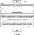
- FIG. 18 is a flow chart 1800 illustrating a method for a remote UE to support UE-to-Network relay communication.
- the remote UE establishes a PC5 connection with a first relay UE for a relay communication with a first network node.
- the remote UE performs a RRC connection establishment procedure with the first network node via the first relay UE.
- the remote UE transmits a first RRC message to a second network node via a second relay UE for requesting RRC connection re-establishment, wherein the first RRC message includes a first C-RNTI of the remote UE.
- the remote UE receives a second RRC message from the second network via the second relay UE for re-establishing a RRC connection between the second network node and the remote UE, wherein the second RRC message includes a second C-RNTI of the remote UE.
- the remote UE could transmit a third RRC message for request of establishing a RRC connection between the first network node and the remote UE to the first network node via the first relay UE.
- the remote UE could also receive a fourth RRC message for establishing the RRC connection between the first network node and the remote UE from the first network node via the first relay UE.
- the first C-RNTI of the remote UE could be included in the fourth RRC message.
- the remote UE could send the first RRC message to the second network node if the remote UE initiates a RRC connection reestablishment procedure, if the remote UE reselects a new relay UE, or if the first relay UE declares a radio link failure on a Uu link with the first network node.
- the first network node could be the same as the second network node.
- the first or second network node could be a base station (e.g. gNB).
- the first relay UE could be the same as the second relay UE.
- the first RRC message could a RRCReestablishmentRequest message;
- the second RRC message could be a RRCReestablishment message;
- the third RRC message could be a RRCSetupRequest message;
- the fourth RRC message could be a RRCSetup message.
- the PC5 connection may be a PC5 RRC connection or a PC5 unicast link.
- the remote UE 300 includes a program code 312 stored in the memory 310.
- the CPU 308 could execute program code 312 to enable the remote UE (i) to establish a PC5 connection with a first relay UE for a relay communication with a first network node, (ii) to perform a RRC connection establishment procedure with the first network node via the first relay UE, (iii) to transmit a first RRC message to a second network node via a second relay UE for requesting RRC connection reestablishment, wherein the first RRC message includes a first C-RNTI of the remote UE, and (iv) to receive a second RRC message from the second network node via the second relay UE for re-establishing a RRC connection between the second network node and the remote UE, wherein the second RRC message includes a second C-RNTI of the
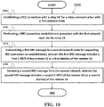
- FIG. 19 is a flow chart 1900 illustrating a method for a remote UE to support UE-to-Network relay communication.
- the remote UE establishes a PC5 connection with a relay UE for a relay communication with a first network node.
- the remote UE performs a RRC connection establishment procedure with the first network node via the relay UE.
- the remote UE transmits a first RRC message to a second network node for requesting RRC connection re-establishment, wherein the first RRC message includes a first C-RNTI of the remote UE or a first identity of the remote UE.
- the remote UE receives a second RRC message from the second network, wherein the second RRC message includes a second C-RNTI of the remote UE or a second identity of the remote UE.
- the remote UE could receive the first C-RNTI of the remote UE or the first identity of the remote UE from the first network node via the relay UE during the RRC connection establishment procedure.
- the remote UE could transmit a first PC5-S message for request of establishing the PC5 connection to the relay UE.
- the remote UE could receive a second PC5-S message for acceptation of establishing the PC5 connection from the relay UE.
- the remote UE could transmit a third RRC message for request of establishing a RRC connection between the first network node and the remote UE to the first network node via the relay UE.
- the remote UE could receive a fourth RRC message for establishing the RRC connection with the first network node from the first network node via the relay UE.
- the remote UE could transmit a fifth RRC message for completion of establishing the RRC connection with the first network node to the first network node via the relay UE.
- the remote UE could enter a RRC _CONNECTED if the RRC connection with the first network node is completed.
- the PC5 connection may be a PC5 RRC connection or a PC5 unicast link.
- the first C-RNTI or the first identity of the remote UE may be included in the fourth RRC message.
- the remote UE could send the first RRC message to the second network node if the remote UE initiates a RRC connection reestablishment procedure, if the remote UE reselects a new relay UE, or if the current relay UE serving the remote UE declares a radio link failure on a Uu link with the first network node.
- the first RRC message could be transmitted to the second network node directly or via the relay UE or a second relay UE.
- the second RRC message could be received from the second network node directly or via the relay UE or a second relay UE.
- the second RRC message could be used for re-establishing a RRC connection with the second network node.
- the first RRC message could include a first physical cell identity (PhysCellId).
- the first physical cell identity could be included in the fourth RRC message.
- the first physical cell identity could also be included in a system information (e.g. Minimum SI) forwarded by the relay UE from the first network node.
- the second RRC message could include a second physical cell identity (PhysCellId).
- the second physical cell identity could be included in a system information (e.g. Minimum SI) forwarded by the relay UE or the second relay UE from the second network node.
- the first network node may be the same as the second network node.
- the first or second network node may be a base station (e.g. gNB).
- the first PC5-S message may be a Direct Communication Request message.
- the second PC5-S message may be a Direct Communication Accept message.
- the third RRC message may be a RRCSetupRequest message.
- the fourth RRC message may be a RRCSetup message.
- the fifth RRC message may be a RRCSetupComplete message.
- the first RRC message may be a RRCReestablishmentRequest message.
- the second RRC message may be a RRCReestablishment message.
- the remote UE 300 includes a program code 312 stored in the memory 310.
- the CPU 308 could execute program code 312 to enable the remote UE (i) to establish a PC5 connection with a relay UE for a relay communication with a first network node, (ii) to perform a RRC connection establishment procedure with the first network node via the relay UE, (iii) to transmit a first RRC message to a second network node for requesting RRC connection re-establishment, wherein the first RRC message includes a first C-RNTI of the remote UE or a first identity of the remote UE, and (iv) to receive a second RRC message from the second network, wherein the second RRC message includes a second C-RNTI of the remote UE or a second identity of the remote UE.
- the CPU 308 can execute the program code 312
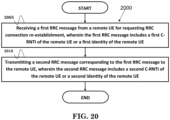
- FIG. 20 is a flow chart 2000 illustrating a method for a second network node to support UE-to-Network relay communication.
- the second network node receives a first RRC message from a remote UE for requesting RRC connection re-establishment, wherein the first RRC message includes a first C-RNTI of the remote UE or a first identity of the remote UE.
- the second network node transmits a second RRC message corresponding to the first RRC message to the remote UE, wherein the second RRC message includes a second C-RNTI of the remote UE or a second identity of the remote UE.
- the second network node could perform a RRC connection establishment procedure with a relay UE, wherein the relay UE establishes a PC5 connection with the remote UE for a relay communication. Furthermore, the second network node could receive a third RRC message corresponding to the second RRC message from the remote UE.
- the PC5 connection may be a PC5 RRC connection or a PC5 unicast link.
- the second RRC message could be used for re-establishing a RRC connection with the second network node.
- the third RRC message could be used for completing the RRC connection reestablishment.
- the first C-RNTI of the remote UE or the first identity of the remote UE could be provided by a first network node.
- the first RRC message could be received from the remote UE directly or via the relay UE.
- the second RRC message could be transmitted to the remote UE directly or via the relay UE.
- the third RRC message could be received from the remote UE directly or via the relay UE.
- the first RRC message may include a first physical cell identity (PhysCellId).
- the first physical cell identity could be provided by the first network node.
- the second RRC message may also include a second physical cell identity (PhysCellId).
- the second physical cell identity could be included in a system information (e.g. Minimum SI) forwarded by the relay UE or a second relay UE from the second network node.
- the second physical cell identity (PhysCellId) could be used for the remote UE to include it in another RRC message for requesting RRC connection re-establishment.
- the first network node could be the same as the second network node.
- the second RRC message may not include the second C-RNTI of the remote UE or the second identity of the remote UE, or may include the first C-RNTI of the remote UE or the first identity of the remote UE if the second network node is the same as the first network node.
- the second RRC message may include the second C-RNTI of the remote UE or the second identity of the remote UE if the second network node is different from the first network node.
- the first or second network node could be a base station (e.g. gNB).
- the first RRC message may be a RRCReestablishmentRequest message.
- the second RRC message may be a RRCReestablishment message.
- the third RRC message may be a RRCReestablishmentComplete message.
- the second network node 300 includes a program code 312 stored in the memory 310.
- the CPU 308 could execute program code 312 to enable the second network node (i) to receive a first RRC message from a remote UE for requesting RRC connection re-establishment, wherein the first RRC message includes a first C-RNTI of the remote UE or a first identity of the remote UE, and (ii) to transmit a second RRC message corresponding to the first RRC message to the remote UE, wherein the second RRC message includes a second C-RNTI of the remote UE or a second identity of the remote UE.
- the CPU 308 can execute the program code 312 to perform all of the above-described actions and steps or others described herein.
- concurrent channels could be established based on pulse repetition frequencies.
- concurrent channels could be established based on pulse position or offsets.
- concurrent channels could be established based on time hopping sequences.
- concurrent channels could be established based on pulse repetition frequencies, pulse positions or offsets, and time hopping sequences.
- the various illustrative logical blocks, modules, and circuits described in connection with the aspects disclosed herein may be implemented within or performed by an integrated circuit ("IC"), an access terminal, or an access point.
- the IC may comprise a general purpose processor, a digital signal processor (DSP), an application specific integrated circuit (ASIC), a field programmable gate array (FPGA) or other programmable logic device, discrete gate or transistor logic, discrete hardware components, electrical components, optical components, mechanical components, or any combination thereof designed to perform the functions described herein, and may execute codes or instructions that reside within the IC, outside of the IC, or both.
- a general purpose processor may be a microprocessor, but in the alternative, the processor may be any conventional processor, controller, microcontroller, or state machine.
- a processor may also be implemented as a combination of computing devices, e.g., a combination of a DSP and a microprocessor, a plurality of microprocessors, one or more microprocessors in conjunction with a DSP core, or any other such configuration.
- a software module e.g., including executable instructions and related data
- other data may reside in a data memory such as RAM memory, flash memory, ROM memory, EPROM memory, EEPROM memory, registers, a hard disk, a removable disk, a CD-ROM, or any other form of computer-readable storage medium known in the art.
- a sample storage medium may be coupled to a machine such as, for example, a computer/processor (which may be referred to herein, for convenience, as a "processor") such the processor can read information (e.g., code) from and write information to the storage medium.
- a sample storage medium may be integral to the processor.
- the processor and the storage medium may reside in an ASIC.
- the ASIC may reside in user equipment.
- the processor and the storage medium may reside as discrete components in user equipment.
- any suitable computer-program product may comprise a computer-readable medium comprising codes relating to one or more of the aspects of the disclosure.
- a computer program product may comprise packaging materials.
Landscapes
- Engineering & Computer Science (AREA)
- Computer Networks & Wireless Communication (AREA)
- Signal Processing (AREA)
- Databases & Information Systems (AREA)
- Mobile Radio Communication Systems (AREA)
- Radio Relay Systems (AREA)
Claims (12)
- Verfahren für eine ferne Teilnehmerausrüstung, im Folgenden auch als UE bezeichnet, um eine UE-zu-Netzwerk-Weiterleitungskommunikation zu unterstützen, umfassend:Einrichten einer PC5-Verbindung mit einer ersten Weiterleitungs-UE für eine Kommunikation mit einem ersten Netzwerkknoten (1805) über die erste Weiterleitungs-UE;Ausführen einer Funkressourcensteuerung-, im Folgenden auch als RRC bezeichnet, Verbindungseinrichtungsprozedur mit dem ersten Netzwerkknoten über die erste Weiterleitungs-UE zum Einrichten einer RRC-Verbindung zwischen der fernen UE und dem ersten Netzwerkknoten (1810); undEmpfangen eines Sicherheitsmoduskommandos von dem ersten Netzwerkknoten über die erste Weiterleitungs-UE, wobei das Sicherheitsmoduskommando für eine Aktivierung einer Access-Stratum-, im Folgenden auch als AS bezeichnet, Sicherheit auf der RRC-Verbindung verwendet wird;gekennzeichnet durchEmpfangen einer RRC-Rekonfigurationsnachricht von dem ersten Netzwerkknoten über die erste Weiterleitungs-UE, wobei die RRC-Rekonfigurationsnachricht einen Cell-Radio-Network-Temporary-Identifier, im Folgenden auch als C-RNTI bezeichnet, der fernen UE umfasst (1820); undSenden einer RRC-Rekonfigurationsabschlussnachricht an den ersten Netzwerkknoten über die erste Weiterleitungs-UE als Reaktion auf den Empfang der RRC-Rekonfigurationsnachricht von dem ersten Netzwerkknoten.
- Verfahren gemäß Anspruch 1, wobei das Ausführen der RRC-Verbindungseinrichtungsprozedur mit dem ersten Netzwerkknoten über die erste Weiterleitungs-UE weiter umfasst:
Senden einer ersten RRC-Nachricht zur Anforderung eines Einrichtens der RRC-Verbindung zwischen dem ersten Netzwerkknoten und der fernen UE an den ersten Netzwerkknoten über die erste Weiterleitungs-UE. - Verfahren gemäß Anspruch 2, wobei das Ausführen der RRC-Verbindungseinrichtungsprozedur mit dem ersten Netzwerkknoten über die erste Weiterleitungs-UE weiter umfasst:
Empfangen einer zweiten RRC-Nachricht zum Einrichten der RRC-Verbindung zwischen dem ersten Netzwerkknoten und der fernen UE von dem ersten Netzwerkknoten über die erste Weiterleitungs-UE. - Verfahren gemäß Anspruch 1, weiter umfassend:
Senden einer dritten RRC-Nachricht an einen zweiten Netzwerkknoten über eine zweite Weiterleitungs-UE zum Anfordern einer RRC-Verbindungswiedereinrichtung, wenn die ferne UE eine RRC-Verbindungswiedereinrichtungsprozedur initiiert, wobei die dritte RRC-Nachricht den C-RNTI der fernen UE umfasst. - Verfahren gemäß Anspruch 4, wobei die ferne UE die RRC-Verbindungswiedereinrichtungsprozedur initiiert, wenn die ferne UE erneut eine neue Weiterleitungs-UE auswählt oder wenn die erste Weiterleitungs-UE einen Funkverbindungsfehler auf einer Uu-Verbindung mit dem ersten Netzwerkknoten deklariert.
- Verfahren gemäß Anspruch 4, wobei der erste Netzwerkknoten der gleiche ist wie der zweite Netzwerkknoten.
- Verfahren gemäß Anspruch 4, wobei die erste Weiterleitungs-UE die gleiche ist wie die zweite Weiterleitungs-UE.
- Verfahren gemäß Anspruch 1, wobei die RRC-Rekonfigurationsnachricht eine erste oder früheste RRC-Rekonfigurationsnachricht ist, die von dem ersten Netzwerkknoten empfangen wird, nachdem die AS-Sicherheit aktiviert ist, und/oder die RRC-Rekonfigurationsnachricht verwendet wird, um mindestens einen neuen Datenfunkträger, im Folgenden auch als DRB bezeichnet, einzurichten.
- Verfahren gemäß Anspruch 4, wobei die erste RRC-Nachricht eine RRCSetupRequest-Nachricht ist, die zweite RRC-Nachricht eine RRCSetup-Nachricht ist und die dritte RRC-Nachricht eine RRCReestablishmentRequest-Nachricht ist.
- Verfahren gemäß Anspruch 1, wobei die PC5-Verbindung eine PC5-RRC-Verbindung oder eine PC5-Unicast-Verbindung ist.
- Ferne Teilnehmerausrüstung, im Folgenden auch als UE bezeichnet, zur Unterstützung einer UE-zu-Netzwerk-Weiterleitungskommunikation, aufweisend:eine Steuerungsschaltung (306);einen Prozessor (308), der in der Steuerungsschaltung (306) installiert ist; undeinen Speicher (310), der in der Steuerungsschaltung (306) installiert und betriebsfähig mit dem Prozessor (308) verbunden ist;dadurch gekennzeichnet, dass der Prozessor (308) eingerichtet ist, einen Programm-Code (312), der in dem Speicher (310) gespeichert ist, auszuführen, um die in einem der vorstehenden Ansprüche definierten Verfahrensschritte auszuführen.
- Verfahren für einen Netzwerkknoten, um eine UE-zu-Netzwerk-Weiterleitungskommunikation zu unterstützen, umfassend:Einrichten einer ersten Funkressourcensteuerung-, im Folgenden auch als RRC bezeichnet, Verbindung mit einer Weiterleitungs-Teilnehmerausrüstung, im Folgenden auch als -UE bezeichnet;Einreichten einer zweiten RRC-Verbindung mit einer fernen UE über die Weiterleitungs-UE; undSenden eines Sicherheitsmoduskommandos an die ferne UE über die Weiterleitungs-UE, wobei das Sicherheitsmoduskommando für eine Aktivierung einer Access-Stratum-, im Folgenden auch als AS bezeichnet, Sicherheit auf der zweiten RRC-Verbindung verwendet wird;gekennzeichnet durchSenden einer RRC-Rekonfigurationsnachricht an die ferne UE über die Weiterleitungs-UE, wobei die RRC-Rekonfigurationsnachricht einen Cell-Radio-Network-Temporary-Identifier, im Folgenden auch als C-RNTI bezeichnet, der fernen UE umfasst, und wobei die RRC-Rekonfigurationsnachricht eine erste oder früheste RRC-Rekonfigurationsnachricht ist, die an die ferne UE gesendet wird, nachdem die AS-Sicherheit aktiviert ist.
Applications Claiming Priority (1)
| Application Number | Priority Date | Filing Date | Title |
|---|---|---|---|
| US202063120458P | 2020-12-02 | 2020-12-02 |
Publications (2)
| Publication Number | Publication Date |
|---|---|
| EP4009732A1 EP4009732A1 (de) | 2022-06-08 |
| EP4009732B1 true EP4009732B1 (de) | 2023-03-22 |
Family
ID=78725278
Family Applications (1)
| Application Number | Title | Priority Date | Filing Date |
|---|---|---|---|
| EP21209494.0A Active EP4009732B1 (de) | 2020-12-02 | 2021-11-22 | Verfahren und vorrichtung zur unterstützung von benutzergerät-netzwerk-relais-kommunikation in einem drahtlosen kommunikationssystem |
Country Status (5)
| Country | Link |
|---|---|
| US (1) | US11672033B2 (de) |
| EP (1) | EP4009732B1 (de) |
| KR (1) | KR20220077869A (de) |
| CN (2) | CN114585045A (de) |
| ES (1) | ES2944343T3 (de) |
Families Citing this family (21)
| Publication number | Priority date | Publication date | Assignee | Title |
|---|---|---|---|---|
| US11856630B2 (en) * | 2020-07-22 | 2023-12-26 | Samsung Electronics Co., Ltd. | Method and apparatus for handling a protocol supporting suspension and resumption of secondary cell group (SCG) in dual connectivity technology supported by next-generation mobile communication system |
| CN114599121A (zh) * | 2020-12-03 | 2022-06-07 | 夏普株式会社 | 由用户设备执行的方法及用户设备 |
| CN114641089B (zh) * | 2020-12-15 | 2025-02-28 | 华为技术有限公司 | 一种通信方法、装置及系统 |
| EP4266819B1 (de) * | 2021-04-02 | 2025-12-17 | Guangdong Oppo Mobile Telecommunications Corp., Ltd. | Relaisverbindungsherstellungsverfahren, und vorrichtung |
| EP4322656A4 (de) * | 2021-04-30 | 2024-06-05 | Guangdong Oppo Mobile Telecommunications Corp., Ltd. | Verfahren und vorrichtung zur übertragung von entdeckungsnachrichten, vorrichtung und speichermedium |
| CN117280848A (zh) * | 2021-05-12 | 2023-12-22 | 诺基亚技术有限公司 | (层2)侧链路中继中的远程ue初始接入 |
| US12127112B2 (en) * | 2021-07-26 | 2024-10-22 | Qualcomm Incorporated | Integrated access and backhaul sidelink communications |
| WO2023014157A1 (ko) * | 2021-08-05 | 2023-02-09 | 엘지전자 주식회사 | 무선통신시스템에서 path switching 및 측정 보고에 관련된 리모트 ue의 동작 방법. |
| US20230039795A1 (en) * | 2021-08-06 | 2023-02-09 | Telefonaktiebolaget Lm Ericsson (Publ) | Identifying a user equipment, ue, for subsequent network reestablishment after a radio link failure during an initial network establishment attempt |
| WO2023039791A1 (en) * | 2021-09-16 | 2023-03-23 | Qualcomm Incorporated | Rrc timer for layer 2 ue-to-network relay |
| US20240388908A1 (en) * | 2021-09-20 | 2024-11-21 | Telefonaktiebolaget Lm Ericsson (Publ) | Backward compatibility handling when adding new integrity protection and ciphering algorithms |
| WO2024065171A1 (en) * | 2022-09-27 | 2024-04-04 | Mediatek Inc. | Relay ue selection and admission |
| KR20240059376A (ko) * | 2022-10-27 | 2024-05-07 | 삼성전자주식회사 | 무선 통신 시스템에서 단말 릴레이를 통해 전송되는 원격단말 패킷의 무결성을 처리하는 방법 및 장치 |
| WO2024128826A1 (ko) * | 2022-12-14 | 2024-06-20 | 엘지전자 주식회사 | 무선통신시스템에서 qos에 기초한 릴레이 선택 또는 재선택에 관련된 동작 방법 |
| KR20250037407A (ko) * | 2023-02-16 | 2025-03-17 | 지티이 코포레이션 | 디바이스 대 디바이스 릴레이 통신을 위한 방법 |
| KR20240163454A (ko) * | 2023-05-10 | 2024-11-19 | 주식회사 케이티 | 향상된 무선 커넥티비티를 갖는 무선 통신을 수행하기 위한 방법 및 장치 |
| KR102881372B1 (ko) * | 2023-07-13 | 2025-11-07 | 아서스 테크놀러지 라이센싱 아이엔씨. | 무선 통신 시스템에서 ue-대-ue 릴레이 통신을 위해 소스 최종 ue를 추가하는 릴레이 ue에 대한 방법 및 장치 |
| US20250081046A1 (en) * | 2023-08-31 | 2025-03-06 | Qualcomm Incorporated | Cellular connection over non-cellular access via gateway |
| WO2024094231A1 (en) * | 2024-01-24 | 2024-05-10 | Lenovo (Beijing) Limited | Methods and apparatuses for a discovery mechanism in a relay case with multiple hops |
| CN121310307A (zh) * | 2024-07-09 | 2026-01-09 | 华为技术有限公司 | 一种通信方法、通信装置和通信系统 |
| CN121645574A (zh) * | 2024-08-30 | 2026-03-10 | 华硕技术授权股份有限公司 | 无线通信系统中用于srb0消息传送的方法和设备 |
Family Cites Families (22)
| Publication number | Priority date | Publication date | Assignee | Title |
|---|---|---|---|---|
| US9357459B2 (en) * | 2011-12-08 | 2016-05-31 | Interdigital Patent Holdings, Inc. | Method and apparatus for cross link establishment |
| KR102083322B1 (ko) * | 2013-08-22 | 2020-03-03 | 삼성전자주식회사 | 이동 통신 시스템에서 고립 사용자 단말기에 대한 디바이스-투-디바이스 통신 기반 서비스 제공 장치 및 방법 |
| EP3627723B1 (de) * | 2015-07-24 | 2025-10-15 | Panasonic Intellectual Property Corporation of America | Verbesserte ue-aktivierung eines prose-relais |
| US10791587B2 (en) * | 2016-02-05 | 2020-09-29 | Lg Electronics Inc. | V2X operation method performed by terminal in wireless communication system and terminal using same |
| WO2017168702A1 (ja) * | 2016-03-31 | 2017-10-05 | 富士通株式会社 | 無線通信システム、無線機器、リレーノード、及び、基地局 |
| US10368393B2 (en) * | 2016-06-10 | 2019-07-30 | Nokia Technologies Oy | Methods and apparatuses for enhancing the setup of carrier aggregation, dual connectivity, multi connectivity, license assisted access, or LTE-WLAN in communications networks |
| EP3520563A1 (de) * | 2016-09-30 | 2019-08-07 | Telefonaktiebolaget LM Ericsson (PUBL) | Herstellung einer funkressourcenkontrollverbindung |
| CN110036667A (zh) * | 2016-12-30 | 2019-07-19 | 夏普株式会社 | 用于新无线电移动性的系统和方法 |
| US11013044B2 (en) * | 2017-01-13 | 2021-05-18 | Lg Electronics Inc. | Proximity-based wireless communication method and user equipment |
| WO2018155908A1 (ko) * | 2017-02-22 | 2018-08-30 | 엘지전자(주) | 무선 통신 시스템에서 릴레이를 통한 데이터 송수신 방법 및 이를 위한 장치 |
| US11477836B2 (en) * | 2017-03-30 | 2022-10-18 | Lg Electronics Inc. | Method for performing path reselection in wireless communication system and apparatus therefor |
| CN114513822B (zh) * | 2017-08-11 | 2024-05-03 | 华为技术有限公司 | 一种路径转换方法、相关装置及系统 |
| US11129017B2 (en) * | 2017-09-28 | 2021-09-21 | Futurewei Technologies, Inc. | System and method for security activation with session granularity |
| WO2019241235A1 (en) * | 2018-06-11 | 2019-12-19 | Ofinno, Llc | Base station network sharing configuration |
| WO2020066605A1 (ja) * | 2018-09-26 | 2020-04-02 | 京セラ株式会社 | 中継装置 |
| JP7052146B2 (ja) * | 2019-03-28 | 2022-04-11 | 京セラ株式会社 | 通信制御方法 |
| CN115460720B (zh) * | 2019-08-13 | 2025-07-15 | 苹果公司 | 远程无线设备的无线电资源控制连接过程 |
| CN114514771B (zh) * | 2019-10-03 | 2024-06-25 | 瑞典爱立信有限公司 | 用于早期测量报告的增强过程 |
| CN111432469B (zh) * | 2020-03-05 | 2022-04-12 | 华为技术有限公司 | 一种通信方法及相关装置 |
| WO2022052092A1 (en) * | 2020-09-14 | 2022-03-17 | Mediatek Singapore Pte. Ltd. | Connection establishment for a layer 2 ue-to-network relay |
| TWI804992B (zh) * | 2020-09-22 | 2023-06-11 | 聯發科技股份有限公司 | 層2使用者設備透過網路中繼進行信令傳輸的方法 |
| CN114615719A (zh) * | 2020-11-23 | 2022-06-10 | 华硕电脑股份有限公司 | 无线通信系统中支持ue到网络的中继通信的方法和设备 |
-
2021
- 2021-11-22 EP EP21209494.0A patent/EP4009732B1/de active Active
- 2021-11-22 ES ES21209494T patent/ES2944343T3/es active Active
- 2021-11-22 CN CN202111388628.XA patent/CN114585045A/zh active Pending
- 2021-11-22 US US17/532,432 patent/US11672033B2/en active Active
- 2021-11-22 CN CN202411706783.5A patent/CN119584239A/zh active Pending
- 2021-11-22 KR KR1020210161063A patent/KR20220077869A/ko not_active Ceased
Also Published As
| Publication number | Publication date |
|---|---|
| CN114585045A (zh) | 2022-06-03 |
| ES2944343T3 (es) | 2023-06-20 |
| US11672033B2 (en) | 2023-06-06 |
| US20220174758A1 (en) | 2022-06-02 |
| KR20220077869A (ko) | 2022-06-09 |
| CN119584239A (zh) | 2025-03-07 |
| EP4009732A1 (de) | 2022-06-08 |
Similar Documents
| Publication | Publication Date | Title |
|---|---|---|
| EP4009732B1 (de) | Verfahren und vorrichtung zur unterstützung von benutzergerät-netzwerk-relais-kommunikation in einem drahtlosen kommunikationssystem | |
| US12004243B2 (en) | Method and apparatus for supporting UE-to-network relay communication in a wireless communication system | |
| EP3972368B1 (de) | Verfahren und vorrichtung für prozess der übertragung kleiner daten (sdt) in einem drahtloskommunikationssystem | |
| EP3823410B1 (de) | Verfahren und vorrichtung für die beantragung von sidelink-übertragungsressourcen in einem drahtloskommunikationssystem | |
| US12279324B2 (en) | Granular request for early measurement reporting | |
| EP4142176A1 (de) | Verfahren und vorrichtung für ein relais-benutzergerät zur unterstützung der umschaltung von direkten auf indirekte kommunikationswege in einem drahtlosen kommunikationssystem | |
| EP4178306A1 (de) | Verfahren und vorrichtung zur rrc-verbindungsherstellung zur unterstützung von ue-zu-netzwerk-weiterleitung in einem drahtlosen kommunikationssystem | |
| CN114158141B (zh) | 无线通信系统中用于连接恢复程序的方法和设备 | |
| EP4142177A1 (de) | Verfahren und vorrichtung für ein entferntes benutzergerät zur unterstützung der umschaltung von direkten auf indirekte kommunikationswege in einem drahtlosen kommunikationssystem | |
| US20230171825A1 (en) | Method and apparatus for remote user equipment (ue) to perform direct to indirect path switching in a wireless communication system | |
| KR102635850B1 (ko) | 무선 통신 시스템에서 ue-대-네트워크 릴레이 통신을 지원하기 위한 방법 및 장치 | |
| KR102764808B1 (ko) | 무선 통신 시스템에서 ue-대-네트워크 릴레잉을 지원하기 위한 무선 베어러 구성을 위한 방법 및 장치 | |
| EP4175399B1 (de) | Verfahren und vorrichtung zur relais-sidelink-rlc-trägerkonfiguration zur unterstützung von ue-zu-netzwerk-weiterleitung in einem drahtloskommunikationssystem | |
| KR102558795B1 (ko) | 무선 통신 시스템에서 ue-대-네트워크 릴레이 통신을 지원하기 위한 방법 및 장치 | |
| HK40077634B (en) | Methods and apparatus for supporting ue-to-network relay communication in a wireless communication system | |
| HK40077634A (en) | Methods and apparatus for supporting ue-to-network relay communication in a wireless communication system | |
| HK40041928B (en) | Method and apparatus for configuring sidelink communication in a wireless communication system |
Legal Events
| Date | Code | Title | Description |
|---|---|---|---|
| PUAI | Public reference made under article 153(3) epc to a published international application that has entered the european phase |
Free format text: ORIGINAL CODE: 0009012 |
|
| STAA | Information on the status of an ep patent application or granted ep patent |
Free format text: STATUS: THE APPLICATION HAS BEEN PUBLISHED |
|
| AK | Designated contracting states |
Kind code of ref document: A1 Designated state(s): AL AT BE BG CH CY CZ DE DK EE ES FI FR GB GR HR HU IE IS IT LI LT LU LV MC MK MT NL NO PL PT RO RS SE SI SK SM TR |
|
| STAA | Information on the status of an ep patent application or granted ep patent |
Free format text: STATUS: REQUEST FOR EXAMINATION WAS MADE |
|
| 17P | Request for examination filed |
Effective date: 20220623 |
|
| RBV | Designated contracting states (corrected) |
Designated state(s): AL AT BE BG CH CY CZ DE DK EE ES FI FR GB GR HR HU IE IS IT LI LT LU LV MC MK MT NL NO PL PT RO RS SE SI SK SM TR |
|
| STAA | Information on the status of an ep patent application or granted ep patent |
Free format text: STATUS: EXAMINATION IS IN PROGRESS |
|
| 17Q | First examination report despatched |
Effective date: 20220811 |
|
| GRAP | Despatch of communication of intention to grant a patent |
Free format text: ORIGINAL CODE: EPIDOSNIGR1 |
|
| STAA | Information on the status of an ep patent application or granted ep patent |
Free format text: STATUS: GRANT OF PATENT IS INTENDED |
|
| GRAS | Grant fee paid |
Free format text: ORIGINAL CODE: EPIDOSNIGR3 |
|
| INTG | Intention to grant announced |
Effective date: 20221214 |
|
| RIN1 | Information on inventor provided before grant (corrected) |
Inventor name: KUO, RICHARD LEE-CHEE Inventor name: PAN, LI-TE |
|
| GRAA | (expected) grant |
Free format text: ORIGINAL CODE: 0009210 |
|
| STAA | Information on the status of an ep patent application or granted ep patent |
Free format text: STATUS: THE PATENT HAS BEEN GRANTED |
|
| RAP3 | Party data changed (applicant data changed or rights of an application transferred) |
Owner name: ASUSTEK COMPUTER INC. |
|
| REG | Reference to a national code |
Ref country code: HK Ref legal event code: DE Ref document number: 40077634 Country of ref document: HK |
|
| AK | Designated contracting states |
Kind code of ref document: B1 Designated state(s): AL AT BE BG CH CY CZ DE DK EE ES FI FR GB GR HR HU IE IS IT LI LT LU LV MC MK MT NL NO PL PT RO RS SE SI SK SM TR |
|
| REG | Reference to a national code |
Ref country code: GB Ref legal event code: FG4D |
|
| REG | Reference to a national code |
Ref country code: CH Ref legal event code: EP |
|
| REG | Reference to a national code |
Ref country code: IE Ref legal event code: FG4D |
|
| REG | Reference to a national code |
Ref country code: DE Ref legal event code: R096 Ref document number: 602021001694 Country of ref document: DE |
|
| REG | Reference to a national code |
Ref country code: AT Ref legal event code: REF Ref document number: 1556019 Country of ref document: AT Kind code of ref document: T Effective date: 20230415 |
|
| REG | Reference to a national code |
Ref country code: NL Ref legal event code: FP |
|
| REG | Reference to a national code |
Ref country code: ES Ref legal event code: FG2A Ref document number: 2944343 Country of ref document: ES Kind code of ref document: T3 Effective date: 20230620 |
|
| P01 | Opt-out of the competence of the unified patent court (upc) registered |
Effective date: 20230512 |
|
| REG | Reference to a national code |
Ref country code: LT Ref legal event code: MG9D |
|
| PG25 | Lapsed in a contracting state [announced via postgrant information from national office to epo] |
Ref country code: RS Free format text: LAPSE BECAUSE OF FAILURE TO SUBMIT A TRANSLATION OF THE DESCRIPTION OR TO PAY THE FEE WITHIN THE PRESCRIBED TIME-LIMIT Effective date: 20230322 Ref country code: NO Free format text: LAPSE BECAUSE OF FAILURE TO SUBMIT A TRANSLATION OF THE DESCRIPTION OR TO PAY THE FEE WITHIN THE PRESCRIBED TIME-LIMIT Effective date: 20230622 Ref country code: LV Free format text: LAPSE BECAUSE OF FAILURE TO SUBMIT A TRANSLATION OF THE DESCRIPTION OR TO PAY THE FEE WITHIN THE PRESCRIBED TIME-LIMIT Effective date: 20230322 Ref country code: LT Free format text: LAPSE BECAUSE OF FAILURE TO SUBMIT A TRANSLATION OF THE DESCRIPTION OR TO PAY THE FEE WITHIN THE PRESCRIBED TIME-LIMIT Effective date: 20230322 Ref country code: HR Free format text: LAPSE BECAUSE OF FAILURE TO SUBMIT A TRANSLATION OF THE DESCRIPTION OR TO PAY THE FEE WITHIN THE PRESCRIBED TIME-LIMIT Effective date: 20230322 |
|
| REG | Reference to a national code |
Ref country code: AT Ref legal event code: MK05 Ref document number: 1556019 Country of ref document: AT Kind code of ref document: T Effective date: 20230322 |
|
| PG25 | Lapsed in a contracting state [announced via postgrant information from national office to epo] |
Ref country code: SE Free format text: LAPSE BECAUSE OF FAILURE TO SUBMIT A TRANSLATION OF THE DESCRIPTION OR TO PAY THE FEE WITHIN THE PRESCRIBED TIME-LIMIT Effective date: 20230322 Ref country code: GR Free format text: LAPSE BECAUSE OF FAILURE TO SUBMIT A TRANSLATION OF THE DESCRIPTION OR TO PAY THE FEE WITHIN THE PRESCRIBED TIME-LIMIT Effective date: 20230623 Ref country code: FI Free format text: LAPSE BECAUSE OF FAILURE TO SUBMIT A TRANSLATION OF THE DESCRIPTION OR TO PAY THE FEE WITHIN THE PRESCRIBED TIME-LIMIT Effective date: 20230322 |
|
| PG25 | Lapsed in a contracting state [announced via postgrant information from national office to epo] |
Ref country code: SM Free format text: LAPSE BECAUSE OF FAILURE TO SUBMIT A TRANSLATION OF THE DESCRIPTION OR TO PAY THE FEE WITHIN THE PRESCRIBED TIME-LIMIT Effective date: 20230322 Ref country code: RO Free format text: LAPSE BECAUSE OF FAILURE TO SUBMIT A TRANSLATION OF THE DESCRIPTION OR TO PAY THE FEE WITHIN THE PRESCRIBED TIME-LIMIT Effective date: 20230322 Ref country code: PT Free format text: LAPSE BECAUSE OF FAILURE TO SUBMIT A TRANSLATION OF THE DESCRIPTION OR TO PAY THE FEE WITHIN THE PRESCRIBED TIME-LIMIT Effective date: 20230724 Ref country code: EE Free format text: LAPSE BECAUSE OF FAILURE TO SUBMIT A TRANSLATION OF THE DESCRIPTION OR TO PAY THE FEE WITHIN THE PRESCRIBED TIME-LIMIT Effective date: 20230322 Ref country code: AT Free format text: LAPSE BECAUSE OF FAILURE TO SUBMIT A TRANSLATION OF THE DESCRIPTION OR TO PAY THE FEE WITHIN THE PRESCRIBED TIME-LIMIT Effective date: 20230322 |
|
| PG25 | Lapsed in a contracting state [announced via postgrant information from national office to epo] |
Ref country code: SK Free format text: LAPSE BECAUSE OF FAILURE TO SUBMIT A TRANSLATION OF THE DESCRIPTION OR TO PAY THE FEE WITHIN THE PRESCRIBED TIME-LIMIT Effective date: 20230322 Ref country code: PL Free format text: LAPSE BECAUSE OF FAILURE TO SUBMIT A TRANSLATION OF THE DESCRIPTION OR TO PAY THE FEE WITHIN THE PRESCRIBED TIME-LIMIT Effective date: 20230322 Ref country code: IS Free format text: LAPSE BECAUSE OF FAILURE TO SUBMIT A TRANSLATION OF THE DESCRIPTION OR TO PAY THE FEE WITHIN THE PRESCRIBED TIME-LIMIT Effective date: 20230722 |
|
| REG | Reference to a national code |
Ref country code: DE Ref legal event code: R097 Ref document number: 602021001694 Country of ref document: DE |
|
| PLBE | No opposition filed within time limit |
Free format text: ORIGINAL CODE: 0009261 |
|
| STAA | Information on the status of an ep patent application or granted ep patent |
Free format text: STATUS: NO OPPOSITION FILED WITHIN TIME LIMIT |
|
| PG25 | Lapsed in a contracting state [announced via postgrant information from national office to epo] |
Ref country code: SI Free format text: LAPSE BECAUSE OF FAILURE TO SUBMIT A TRANSLATION OF THE DESCRIPTION OR TO PAY THE FEE WITHIN THE PRESCRIBED TIME-LIMIT Effective date: 20230322 Ref country code: DK Free format text: LAPSE BECAUSE OF FAILURE TO SUBMIT A TRANSLATION OF THE DESCRIPTION OR TO PAY THE FEE WITHIN THE PRESCRIBED TIME-LIMIT Effective date: 20230322 Ref country code: CZ Free format text: LAPSE BECAUSE OF FAILURE TO SUBMIT A TRANSLATION OF THE DESCRIPTION OR TO PAY THE FEE WITHIN THE PRESCRIBED TIME-LIMIT Effective date: 20230322 |
|
| 26N | No opposition filed |
Effective date: 20240102 |
|
| PG25 | Lapsed in a contracting state [announced via postgrant information from national office to epo] |
Ref country code: MC Free format text: LAPSE BECAUSE OF FAILURE TO SUBMIT A TRANSLATION OF THE DESCRIPTION OR TO PAY THE FEE WITHIN THE PRESCRIBED TIME-LIMIT Effective date: 20230322 |
|
| PG25 | Lapsed in a contracting state [announced via postgrant information from national office to epo] |
Ref country code: LU Free format text: LAPSE BECAUSE OF NON-PAYMENT OF DUE FEES Effective date: 20231122 |
|
| PG25 | Lapsed in a contracting state [announced via postgrant information from national office to epo] |
Ref country code: MC Free format text: LAPSE BECAUSE OF FAILURE TO SUBMIT A TRANSLATION OF THE DESCRIPTION OR TO PAY THE FEE WITHIN THE PRESCRIBED TIME-LIMIT Effective date: 20230322 Ref country code: LU Free format text: LAPSE BECAUSE OF NON-PAYMENT OF DUE FEES Effective date: 20231122 |
|
| REG | Reference to a national code |
Ref country code: BE Ref legal event code: MM Effective date: 20231130 |
|
| REG | Reference to a national code |
Ref country code: IE Ref legal event code: MM4A |
|
| PG25 | Lapsed in a contracting state [announced via postgrant information from national office to epo] |
Ref country code: IE Free format text: LAPSE BECAUSE OF NON-PAYMENT OF DUE FEES Effective date: 20231122 |
|
| PG25 | Lapsed in a contracting state [announced via postgrant information from national office to epo] |
Ref country code: BE Free format text: LAPSE BECAUSE OF NON-PAYMENT OF DUE FEES Effective date: 20231130 |
|
| PG25 | Lapsed in a contracting state [announced via postgrant information from national office to epo] |
Ref country code: IE Free format text: LAPSE BECAUSE OF NON-PAYMENT OF DUE FEES Effective date: 20231122 Ref country code: BE Free format text: LAPSE BECAUSE OF NON-PAYMENT OF DUE FEES Effective date: 20231130 |
|
| PG25 | Lapsed in a contracting state [announced via postgrant information from national office to epo] |
Ref country code: BG Free format text: LAPSE BECAUSE OF FAILURE TO SUBMIT A TRANSLATION OF THE DESCRIPTION OR TO PAY THE FEE WITHIN THE PRESCRIBED TIME-LIMIT Effective date: 20230322 |
|
| PG25 | Lapsed in a contracting state [announced via postgrant information from national office to epo] |
Ref country code: BG Free format text: LAPSE BECAUSE OF FAILURE TO SUBMIT A TRANSLATION OF THE DESCRIPTION OR TO PAY THE FEE WITHIN THE PRESCRIBED TIME-LIMIT Effective date: 20230322 |
|
| REG | Reference to a national code |
Ref country code: CH Ref legal event code: PL |
|
| REG | Reference to a national code |
Ref country code: CH Ref legal event code: PL |
|
| PG25 | Lapsed in a contracting state [announced via postgrant information from national office to epo] |
Ref country code: CH Free format text: LAPSE BECAUSE OF NON-PAYMENT OF DUE FEES Effective date: 20241130 |
|
| PG25 | Lapsed in a contracting state [announced via postgrant information from national office to epo] |
Ref country code: CY Free format text: LAPSE BECAUSE OF FAILURE TO SUBMIT A TRANSLATION OF THE DESCRIPTION OR TO PAY THE FEE WITHIN THE PRESCRIBED TIME-LIMIT; INVALID AB INITIO Effective date: 20211122 |
|
| PGFP | Annual fee paid to national office [announced via postgrant information from national office to epo] |
Ref country code: IT Payment date: 20250908 Year of fee payment: 5 Ref country code: NL Payment date: 20250908 Year of fee payment: 5 |
|
| PGFP | Annual fee paid to national office [announced via postgrant information from national office to epo] |
Ref country code: GB Payment date: 20250901 Year of fee payment: 5 |
|
| PGFP | Annual fee paid to national office [announced via postgrant information from national office to epo] |
Ref country code: FR Payment date: 20250901 Year of fee payment: 5 |
|
| PG25 | Lapsed in a contracting state [announced via postgrant information from national office to epo] |
Ref country code: TR Free format text: LAPSE BECAUSE OF FAILURE TO SUBMIT A TRANSLATION OF THE DESCRIPTION OR TO PAY THE FEE WITHIN THE PRESCRIBED TIME-LIMIT Effective date: 20230322 |
|
| PGFP | Annual fee paid to national office [announced via postgrant information from national office to epo] |
Ref country code: DE Payment date: 20250821 Year of fee payment: 5 |
|
| PG25 | Lapsed in a contracting state [announced via postgrant information from national office to epo] |
Ref country code: HU Free format text: LAPSE BECAUSE OF FAILURE TO SUBMIT A TRANSLATION OF THE DESCRIPTION OR TO PAY THE FEE WITHIN THE PRESCRIBED TIME-LIMIT; INVALID AB INITIO Effective date: 20211122 |
|
| PGFP | Annual fee paid to national office [announced via postgrant information from national office to epo] |
Ref country code: ES Payment date: 20260112 Year of fee payment: 5 |