EP4009759B1 - Dispositif de montage, système de montage et procédé d'inspection/de montage - Google Patents
Dispositif de montage, système de montage et procédé d'inspection/de montage Download PDFInfo
- Publication number
- EP4009759B1 EP4009759B1 EP19940270.2A EP19940270A EP4009759B1 EP 4009759 B1 EP4009759 B1 EP 4009759B1 EP 19940270 A EP19940270 A EP 19940270A EP 4009759 B1 EP4009759 B1 EP 4009759B1
- Authority
- EP
- European Patent Office
- Prior art keywords
- mounting
- component
- section
- inspection
- reference information
- Prior art date
- Legal status (The legal status is an assumption and is not a legal conclusion. Google has not performed a legal analysis and makes no representation as to the accuracy of the status listed.)
- Active
Links
Images



Classifications
-
- H—ELECTRICITY
- H05—ELECTRIC TECHNIQUES NOT OTHERWISE PROVIDED FOR
- H05K—PRINTED CIRCUITS; CASINGS OR CONSTRUCTIONAL DETAILS OF ELECTRIC APPARATUS; MANUFACTURE OF ASSEMBLAGES OF ELECTRICAL COMPONENTS
- H05K13/00—Apparatus or processes specially adapted for manufacturing or adjusting assemblages of electric components
- H05K13/08—Monitoring manufacture of assemblages
-
- H—ELECTRICITY
- H05—ELECTRIC TECHNIQUES NOT OTHERWISE PROVIDED FOR
- H05K—PRINTED CIRCUITS; CASINGS OR CONSTRUCTIONAL DETAILS OF ELECTRIC APPARATUS; MANUFACTURE OF ASSEMBLAGES OF ELECTRICAL COMPONENTS
- H05K13/00—Apparatus or processes specially adapted for manufacturing or adjusting assemblages of electric components
- H05K13/08—Monitoring manufacture of assemblages
- H05K13/083—Quality monitoring using results from monitoring devices, e.g. feedback loops
-
- H—ELECTRICITY
- H05—ELECTRIC TECHNIQUES NOT OTHERWISE PROVIDED FOR
- H05K—PRINTED CIRCUITS; CASINGS OR CONSTRUCTIONAL DETAILS OF ELECTRIC APPARATUS; MANUFACTURE OF ASSEMBLAGES OF ELECTRICAL COMPONENTS
- H05K13/00—Apparatus or processes specially adapted for manufacturing or adjusting assemblages of electric components
- H05K13/08—Monitoring manufacture of assemblages
- H05K13/081—Integration of optical monitoring devices in assembly lines; Processes using optical monitoring devices specially adapted for controlling devices or machines in assembly lines
- H05K13/0812—Integration of optical monitoring devices in assembly lines; Processes using optical monitoring devices specially adapted for controlling devices or machines in assembly lines the monitoring devices being integrated in the mounting machine, e.g. for monitoring components, leads, component placement
Definitions
- the present specification discloses a mounting device, a mounting system, and an inspection/mounting method.
- a mounting device there has been proposed a device configured to, based on identification information read from a repair substrate requiring repair and read information for work, detect a mounting lane having a production spare capacity because components can be mounted on the repair substrate or a mounting lane having a high throughput, and to display the detected mounting lane (refer to Patent Literature 1, for example).
- this mounting device it is supposed that it is possible to reduce degradation in the production efficiency of the mounting lane when the repair substrate is introduced into the mounting lane.
- Patent Literature 1 JP-A-2014-22681 US 2016/299499 A1 relates to a component mounting apparatus for unloading an electronic component from a component supply unit, and to mount the electronic component to a substrate.
- component parameters are linked to operational parameters of the component mounting apparatus. As initial values, the operational values are tentatively set to default values. When the production is actually performed by the component mounting apparatus, the operational parameters are updated based on acquired component parameters of the actual physical electronic component used.
- JP 2016 201430 A relates to a component mounting apparatus for unloading an electronic component from a component supply unit, and to mount the electronic component to a substrate.
- component parameters are linked to operational parameters of the component mounting apparatus. As initial values, the operational values are tentatively set to default values. When the production is actually performed by the component mounting apparatus, the operational parameters are updated based on acquired component parameters of the actual physical electronic component used.
- Patent Literature 1 the mounting device in Patent Literature 1 described above is based on the premise that a repair substrate removed from a production me is inserted again into some of the mounting lanes, and it has not been considered to reduce the number of substrates that require repair in other methods.
- the present disclosure has been made in view of such problems, and it is a principal object thereof to provide a mounting device, a mounting system, and an inspection/mounting method capable of more efficiently reducing loss of a mounting target subjected to a mounting process.
- the present disclosure employs the following means in order to achieve the above principal object.
- the inspection section when the reference information is updated after an error in the component subjected to a mounting process prior to the mounting device is detected, the inspection section is caused to execute the inspection process using the updated reference information on the component subjected to the mounting process prior to the mounting device.
- the reference information of the mounting device may differ depending on a component, for example, due to a difference in a manufacturing company, a difference of a lot, or the like.
- an error may be determined even if a component is mounted within an allowable range.
- the "mounting target” includes a substrate, a panel including multiple substrates, a three-dimensional solid object, and the like.
- the reference information may include information regarding one or more of a shape, a brightness value, and a characteristic value of a component.
- the inspection process may include one or more of inspection of whether a component is disposed, inspection of a deviation amount of a component, inspection of a shape of a component, and inspection of a characteristic value of a component.
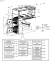
- Fig. 1 is a schematic explanatory diagram illustrating an example of mounting system 10 of the present disclosure.
- Fig. 2 is an explanatory diagram schematically illustrating an outline of a configuration of mounting device 15.
- Fig. 3 is an explanatory diagram illustrating an example of board DS and substrate S.
- Fig. 4 is an explanatory diagram of information stored in memory section 42.
- a left-right direction (X axis), a front-rear direction (Y axis), and an up-down direction (Z axis) are as illustrated in Figs. 1 and 2 .
- Mounting system 10 is configured as, for example, a production line in which mounting devices 15 performing a mounting process for components P on substrate S serving as a mounting target are arranged in a conveyance direction of substrate S.
- a mounting target is described as substrate S but is not particularly limited as long as component P is mounted thereon, and may be a base material having a three-dimensional shape.
- mounting system 10 is configured to include printing device 11, printing inspection device 12, storage section 13, management PC 14, mounting device 15, automatic conveyance vehicle 16, loader 18, host PC 60, and the like.
- Printing device 11 is a device that prints a solder paste or the like on substrate S.
- Printing inspection device 12 is a device that inspects a state of a printed solder.
- Board DS is a mounting target including multiple substrates S. As illustrated in Fig. 3 , board DS includes multiple substrates Sa to Sf on which components Pa to Pd are disposed at the same positions. Here, components Pa to Pd are collectively referred to as component P, and substrates Sa to Sf are collectively referred to as substrate S. Board DS is configured to obtain multiple substrates S by dividing board DS along grooves formed on a top surface after a mounting process and a reflow process.
- Mounting device 15 is a device that picks up component P and mounts component P on substrate S.
- Mounting device 15 has a function of executing a mounting/inspection process for inspecting component missing of substrate S or a state of a component disposed on substrate S.
- Mounting device 15 includes substrate processing section 22, component supply section 24, pickup/imaging section 26, mounting section 30, and mounting controller 40.
- mounting controller 40 is configured as a microprocessor centered on CPU 41, and controls the entire device.
- Mounting controller 40 includes memory section 42 and inspection section 49.
- memory section 42 stores mounting condition information 43, reference information 44, substrate reference information 45, component information 46, substrate information 47, and the like.
- Mounting condition information 43 is a production job, and includes information such as information of component P, a disposition order in which component P is mounted on substrate S, a disposition position, and an attachment position of feeder 25 from which component P is picked up.
- Reference information 44 includes, for example, data such as an image serving as a reference for detecting dispositional deviation or missing of component P.
- Reference information 44 includes substrate reference information 45, component information 46, and the like.
- Substrate reference information 45 is information regarding substrate S on which an inspection process is executed, and includes information regarding substrate S, such as an image, a size, and a shape of substrate S, in a manner associated with an identifier (ID) of substrate S.
- ID identifier
- Component information 46 is information regarding component P on which an inspection process is executed, and includes information regarding component P, such as an image, a size, and a shape of component P, in association with an identifier (ID) of component P.
- Substrate information 47 is information for managing a mounting state or the like of substrate S, and includes, for example, information regarding a disposition position of disposed component P, information regarding the type or a position of a disposition error component that has missed or is disposed to be greatly deviated as a result of inspection, and information a skip region that is a region where a disposition error has occurred.
- Component missing means that component P is not present at a disposition position on substrate S due to some factor although a mounting process for component P is performed.
- a disposition error of component P when a disposition error of component P occurs, in order to prevent further loss of component P, it is possible to select a skip mode in which a predetermined region (for example, specific substrate S) is subjected to a skip process and a process for restricting a mounting process for further components P is executed.
- a disposition error in order to suppress the frequent occurrence of skipping, when a disposition error is repeated a predetermined number of times (for example, three times) at the same disposition position, a process of stopping the device and notifying an operator is executed.
- This substrate information 47 is transmitted to host PC 60 and stored as a substrate information database for production management.
- Error information 48 is information for managing the number of times for which a disposition error has occurred at the same disposition position.
- Error information 48 includes an identifier (ID) of a mounting device in which a disposition error has occurred, a mounting position (coordinates), a type or an ID of a component, the number of errors, and the like. Error information 48 is transmitted to host PC 60 and stored as an error information database for production management.
- Mounting device 15 stores substrate information 47 and error information 48 in memory section 42 after the mounting process is started.
- Inspection section 49 is, for example, a functional block that inspects a state of substrate S or disposed component P based on a captured image of substrate S.
- Mounting controller 40 outputs control signals to substrate processing section 22, component supply section 24, and mounting section 30, and also receives signals from substrate processing section 22, component supply section 24, and mounting section 30.
- Substrate processing section 22 is a unit that carries in, conveys, fixes at a mounting position, and carries out substrate S.
- Substrate processing section 22 has a pair of conveyor belts extending in the left-right direction and spaced apart from each other in the front-rear direction in Fig. 2 .
- Substrate S is conveyed by these conveyor belts.
- Substrate processing section 22 includes two pairs of the conveyor belts, and can convey and fix two substrates S simultaneously.
- Component supply section 24 is a unit that supplies component P to mounting section 30.
- Component supply section 24 attaches feeder 25 including a reel around which a tape serving as a holding member holding component P is wound to at least one attachment portion.
- Component supply section 24 includes a mounting attachment portion attached with feeder 25 used for a mounting process and a buffer attachment portion attached with preliminary feeder 25 in upper and lower stages thereof.
- Feeder 25 includes a controller (not illustrated). The controller stores information such as an ID of a tape included in feeder 25, and the type and the remaining number of components P. When feeder 25 is attached to the attachment portion, the controller transmits information regarding feeder 25 to mounting controller 40.
- Component supply section 24 may include a tray unit having a tray as a holding member on which multiple components P are arranged and placed.
- Pickup/imaging section 26 is a device that captures images of one or more components P in a state of being picked up and held by mounting head 32.
- Pickup/imaging section 26 is disposed between substrate processing section 22 and component supply section 24.
- An imaging range of pickup/imaging section 26 is located above pickup/imaging section 26.
- Pickup/imaging section 26 captures an image of component P when mounting head 32 holding component P passes over pickup/imaging section 26, and outputs the captured image to mounting controller 40.
- mounting controller 40 may execute, for example, inspection of whether a shape and a part of component P are normal, or detection of a deviation amount of a position, rotation, or the like at the time of picking up component P.
- Operation panel 27 includes display section 28 that displays a screen, and operation section 29 that receives an input operation from an operator.
- Display section 28 is configured as a liquid crystal display, and displays an operating state and a setting state of mounting device 15 on a screen.
- Operation section 29 includes a cursor key for moving a cursor in the up-down direction and the left-right direction, a cancel key for canceling an input, a determination key for determining a selected content, and the like, and thus an instruction from the operator can be keyed in.
- Mounting section 30 is a unit that picks up component P from component supply section 24 and disposes component P on substrate S fixed to substrate processing section 22.
- Mounting section 30 includes head moving section 31, mounting head 32, nozzle 33, inspection/imaging section 34, and nozzle storage section 35.
- Head moving section 31 includes a slider moved by being guided by guide rails in the XY-directions, and a motor that drives the slider.
- Mounting head 32 picks up one or more components P and is moved in the XY-directions by head moving section 31.
- Mounting head 32 is detachably attached to the slider.
- One or more nozzles 33 are detachably attached to a lower surface of mounting head 32. Nozzle 33 picks up component P by using a negative pressure.
- a pickup member that picks up component P may be a mechanical chuck or the like that mechanically holds component P in addition to nozzle 33.
- Inspection/imaging section 34 is a camera that captures an image of a region below mounting head 32, and captures an image of, for example, not only component P disposed on substrate S but also a reference mark, a 2D code, or the like formed on substrate S.
- Inspection/imaging section 34 is disposed on the lower surface side of the slider to which mounting head 32 is attached, and is moved in the XY-directions in accordance with the movement of mounting head 32.
- Inspection/imaging section 34 outputs image data of substrate S on which component P is disposed to mounting controller 40.
- Mounting controller 40 causes inspection section 49 to analyze the image data.
- Nozzle storage section 35 accommodates one or more types of nozzles 33 to be attached to mounting head 32.
- Nozzle 33 for picking up component P subjected to a mounting process by another mounting device 15 may be accommodated in a preliminary accommodation section of nozzle storage section
- Storage section 13 is a storage location for temporarily storing feeder 25 used in mounting device 15.
- Storage section 13 is provided under a conveyance device between printing inspection device 12 and mounting device 15.
- Storage section 13 has an attachment portion in the same manner as component supply section 24.
- the controller of feeder 25 transmits the information regarding feeder 25 to management PC 14.
- feeder 25 may be transported by automatic conveyance vehicle 16 or feeder 25 may be transported by an operator.
- Management PC 14 is a device that manages feeder 25, stores execution data or the like executed by loader 18, and manages loader 18.
- Automatic conveyance vehicle 16 automatically conveys feeder 25, a member used in mounting system 10, and the like between a warehouse (not illustrated) and storage section 13. The warehouse stores feeder 25, other members, and the like.
- Loader 18 is a mobile work device, which is a device that is moved in a movement region in front of mounting system 10 (refer to dotted lines in Fig. 1 ), and automatically collects and provides members or the like necessary for a mounting process, such as feeder 25 of mounting device 15.
- Loader 18 includes movement controller 50, memory section 53, accommodation section 54, exchange section 55, moving section 56, and communication section 57.
- Movement controller 50 is configured as a microprocessor centered on CPU 51 and controls the entire device. Movement controller 50 controls the entire device such that feeder 25 is collected from component supply section 24 or feeder 25 is provided to component supply section 24, and feeder 25 is moved to and from storage section 13.
- Memory section 53 is, for example, an HDD that stores various data such as a processing program.
- Accommodation section 54 has an accommodation space for accommodating feeder 25.
- Accommodation section 54 is configured to accommodate, for example, four feeders 25.
- Exchange section 55 is a mechanism that moves feeder 25 in and out as well as moving feeder 25 in the up-down direction (refer to Fig. 2 ).
- Exchange section 55 has a clamp portion that clamps feeder 25, a Y-axis slider that moves the clamp portion in the Y-axis direction (front-rear direction), and a Z-axis slider that moves the clamp portion in the Z-axis direction (up-down direction).
- Exchange section 55 executes attachment and detachment of feeder 25 at a mounting attachment portion, and attachment and detachment of feeder 25 at a buffer attachment portion.
- Moving section 56 is a mechanism that moves loader 18 in the X-axis direction (the left-right direction) along X-axis rail 19 disposed in front of mounting device 15.
- Communication section 57 is an interface that performs exchange of information with external devices such as management PC 14 and mounting device 15.
- Loader 18 outputs the current position or details of executed work to management PC 14.
- Loader 18 is capable of collecting and providing feeder 25, but may be configured to collect and provide members related to the mounting process, such as mounting head 32, nozzle 33, a solder cartridge, a screen mask, and a backup pin for supporting a substrate.
- Host PC 60 (refer to Fig. 1 ) is configured as a server that stores and manages information used by each device of mounting system 10, such as a production plan database including multiple pieces of mounting condition information 43, a substrate information database including multiple pieces of substrate information 47, and error information 48.
- Host PC 60 may input and edit image data, a size, a shape, a color, and the like in reference information 44.
- a control section of host PC 60 outputs updated reference information 44 to any device of mounting system 10, such as mounting device 15.
- FIG. 5 is a flowchart illustrating an example of a mounting/inspection process routine executed by CPU 41 of mounting controller 40 of mounting device 15. This routine is stored in memory section 42 of mounting device 15 and executed in accordance with a starting instruction from an operator. When this routine is started, CPU 41 reads and acquires mounting condition information 43 and reference information 44 of substrate S to be produced this time (S100).
- CPU 41 is assumed to read mounting condition information 43 or reference information 44 acquired from host PC 60 and stored in memory section 42. Next, CPU 41 reads and acquires substrate information 47 of board DS (substrate S) subjected to a mounting process this time, and causes substrate processing section 22 to convey substrate S to a mounting position and to perform a fixing process (S110).
- CPU 41 executes a mounting process (S120).
- CPU 41 sets a component that is a pickup target based on mounting condition information 43, causes mounting head 32 to pick up component P from feeder 25 at a preset position, moves mounting head 32 to a disposition position of component P, and executes a process of disposing component P.
- CPU 41 restricts the mounting process, that is, does not execute the mounting process in order to suppress a loss of component P with respect to a predetermined region in which a disposition error has occurred.
- CPU 41 executes an inspection process for disposed component P (S130).
- CPU 41 causes inspection/imaging section 34 to capture an image of component P subjected to the mounting process by the present mounting device thereof, and acquires an inspection result of each component P based on whether component P is disposed at a predetermined disposition position or whether dispositional deviation such as positional deviation or rotational deviation is within a predetermined allowable range.
- the inspection result includes inspection pass in which there is no component missing, dispositional deviation is small, and a shape is within a designated shape, a dispositional deviation error, a component missing error, and a shape error.
- component P may be subjected to a mounting process by mounting device 15 subsequent to the present mounting device.
- CPU 41 may execute the inspection process collectively after the present mounting device performs the mounting process on all components P, or may repeatedly perform the mounting process and the inspection process.
- CPU 41 determines whether there is an error, when there is an error, stores the error in substrate information 47 or error information 48, and sets a predetermined region that includes component P having an error and on which the mounting process will be skipped by subsequent mounting device 15 (S150).
- CPU 41 determines whether the corresponding error has reached a predetermined number of times set in advance (S 160), and when the predetermined number of times is reached, stops the device, and notifies the operator of checking of reference information 44 (S170).
- predetermined number of times means a threshold value for determining error detection, and includes not only the occurrence of the same error a predetermined number of times on the same substrate S, but also the repetition of the same error a predetermined number of times on different multiple substrates S.
- the reference data of reference information 44 may be different from component P that is actually used, such as a difference in a brightness value (color) differing or a difference in a shape (a lead is long or short), depending on the operator's discrepancy, or a lot or a vendor of component P.
- CPU 41 may erroneously determine that an error has occurred.
- CPU 41 notifies the operator whether there are any such errors. This notification may be performed, for example, by performing a process of displaying a message, an icon, or the like on operation panel 27, by lighting a lamp, or by outputting sound, voice, or the like.
- the operator notified of the checking of reference information 44 checks, for example, whether the content of reference information 44 in host PC 60 and component P used in mounting device 15 are different from each other. In a case where there is no problem in reference information 44, the operator operates operation panel 27 to input information indicating that the process is continued, whereas in a case where reference information 44 is changed, the operator inputs information indicating that reference information 44 is newly updated.
- CPU 41 acquires the input content from the operator from operation panel 27, and when acquiring the input in which reference information 44 has been updated, CPU 41 re-inspects a mounting region that has been subjected to the mounting process prior to the present mounting device by using updated reference information 44 (S190).
- CPU 41 performs a re-inspection process using correct reference information 44 on the region that is not subjected to the mounting process by the present mounting device, and thus obtains a more appropriate inspection result.
- CPU 41 extracts a component missing error from the inspection result, and stores the inspection result including the component missing error in reference information 44 (S200).
- component missing is naturally detected in a predetermined region on which the mounting process is skipped in the skip mode.
- CPU 41 executes a remounting process (S210 to S240). Specifically, CPU 41 determines whether component P to be mounted by mounting device 15 prior to the present mounting device can be picked up by mounting section 30 of the present mounting device (S220). This determination may be performed based on, for example, whether there is corresponding nozzle 33 in nozzle storage section 35, based on correspondence information in which corresponding component P is correlated with mounting head 32 and nozzle 33 that can pick up component P. When corresponding component P can be picked up by the present mounting device, CPU 41 determines whether component P to be remounted by the present mounting device is present in component supply section 24 (S220).
- Feeder 25 used in another mounting device 15 and not used in the present mounting device may be preliminarily attached to a preliminary attachment portion of component supply section 24.
- CPU 41 When component P to be remounted is not present in component supply section 24, CPU 41 outputs a command for providing feeder 25 holding component P to be remounted to component supply section 24, to management PC 14 (S230).
- Management PC 14 outputs a storage position in the storage section 13 storing corresponding feeder 25 and a position of component supply section 24 of mounting device 15 that requires the provision to loader 18, and causes loader 18 to provide feeder 25.
- CPU 41 causes mounting section 30 to execute the remounting process (240).
- Mounting section 30 disposes component P to be remounted that is not scheduled to be subjected to a mounting process by this mounting device 15 on substrate S.
- CPU 41 executes the processes in and after S130. That is, CPU 41 executes an inspection process on remounted component P, and repeatedly performs processes of determining whether there is an error, setting a predetermined region when there is an error, and determining whether the corresponding error has been repeated a predetermined number of times (S140 to S160). Since reference information 44 is updated in S180, the frequency of error detection in mounting device 15 is reduced.
- CPU 41 determines whether the mounting process for current substrate S has been completed (S250). When the mounting process for the current substrate has not been completed, CPU 41 executes the processes in and after S120. That is, CPU 41 continuously executes the mounting process and the inspection process (S120 and S130). On the other hand, when the mounting process for current substrate S has been completed, CPU 41 updates substrate information 47 and controls substrate processing section 22 to discharge substrate S (S260).
- CPU 41 determines whether production of all substrates S set in mounting condition information 43 has been completed (S 270). When the production of all substrates S has not been completed, CPU 41 executes the processes in and after S110. On the other hand, when the production of all substrates S has been completed, this routine is finished. Since such a mounting process is executed by each of mounting devices 15, information regarding which position an error is likely to occur on specific substrate S is integrated and stored in substrate information 47.
- FIG. 6 is an explanatory diagram for describing a specific example of a process of skipping the inspection process and the mounting process, in which Fig. 6A is a diagram illustrating a case where substrate S1 is inspected by mounting device 15a based on inappropriate reference information 44, Fig. 6B is a diagram illustrating a case where substrate S1 is skipped by the next mounting device 15b, and Fig. 6C is a diagram illustrating a case where substrate S1 is skipped by mounting device 15c, substrate S2 is skipped by mounting device 15b, and a device is stopped.
- Fig. 6A is a diagram illustrating a case where substrate S1 is inspected by mounting device 15a based on inappropriate reference information 44
- Fig. 6B is a diagram illustrating a case where substrate S1 is skipped by the next mounting device 15b
- Fig. 6C is a diagram illustrating a case where substrate S1 is skipped by mounting device 15c, substrate S2 is skipped by mounting device 15b, and a device is
- FIG. 7 is an explanatory diagram for describing a specific example of update of component information 46 and the remounting process, in which Fig. 7A is a diagram illustrating a case where reference information 44 is updated and the re-inspection process is performed based on updated reference information 44, Fig. 7B is a diagram illustrating a case where loader 18 is supplemented with feeder 25 to be remounted, Fig. 7C is a diagram illustrating a case where the remounting process is performed, and Fig. 7D is a diagram illustrating a case where remaining components P to be mounted by the present mounting device are mounted.
- mounting device 15a is set to perform a mounting process and an inspection process on an upper stage of substrate S
- the next mounting device 15b is set to perform a mounting process and an inspection process on an intermediate stage of substrate S
- the next mounting device 15c is set to perform a mounting process and an inspection process on a lower stage of substrate S.
- a predetermined number of times which is an allowable number of repetitions of errors, is three, and a skip region is set on one substrate S of board DS.
- board DS1 including substrate Sa1, board DS2 including substrate Sa2, and board DS3 including substrate Sa3 are sequentially supplied to mounting devices 15a, 15b, and 15c from the upper part to the lower part in the drawing over time, and only substrates Sa1 to Sa3 of boards DS1 to DS3 are illustrated for convenience.
- processes for substrates Sb to Sf of board DS are assumed to be the same process as that for substrate Sa of board DS, and detailed descriptions thereof will be omitted.
- mounting device 15a executes a mounting process and an inspection process on substrate Sa1 of board DS1 (S120 and S130). Since an image of component Pa of reference information 44 differs from actual component Pa, inspection section 49 of mounting device 15a erroneously detects that component Pa is missing even though component Pa is appropriately mounted on substrate Sa1, and sets entire substrate Sa1 in a predetermined region where the mounting process is skipped (S150).
- board DS1 is conveyed to mounting device 15b (S260), and board DS2 is carried into mounting device 15a (S110).
- substrate Sa2 of board DS2 similarly to substrate Sa1, it is determined that component Pa that is appropriately mounted is missing, and entire substrate Sa2 is set in a predetermined region where the mounting process is skipped. Since entire substrate Sa1 is the skip region, mounting device 15b does not execute the mounting process on component P.
- board DS1 is conveyed to mounting device 15c
- board DS2 is conveyed to mounting device 15b
- board DS3 is carried into mounting device 15a.
- substrate Sa3 similarly to substrates Sa1 and Sa2
- it is determined that component Pa that is appropriately mounted is missing, and entire substrate Sa3 is set in a predetermined region where the mounting process is skipped.
- mounting devices 15b and 15c do not execute the mounting process on component P.
- the corresponding error reaches a predetermined number of times, that is, three times (S160), mounting devices 15a to 15c are stopped and notify an operator of checking of reference information 44 (S170).
- FIG. 8 is an explanatory diagram illustrating an example of reference information update screen 70 displayed on a display of host PC 60.
- Reference information update screen 70 is a screen displayed when information regarding component P, such as image data, a size, a brightness value, and a characteristic value included in component information 46 is input and updated.
- cursor 71, substrate reference information display field 72, pre-change component information display field 73, post-change component information display field 74, input key 75, and the like are displayed.
- Cursor 71 is used for an operator to give an instruction for selection and entry to an entry field disposed on the screen, and is moved on the screen by operating an input device of host PC 60.
- An image of component P disposed on substrate S is displayed in substrate reference information display field 72.
- Pre-change component information display field 73 is a field in which reference data, information, and the like currently used for component P selected in substrate reference information display field 72 are displayed.
- Post-change component information display field 74 is a field to which updated data of component P displayed in pre-change component information display field 73 is entered.
- Input key 75 includes a selection key, an edit key, a save key, an end key, and the like.
- the operator checks the displayed contents, presses the edit key to edit the contents, and presses the save key to store reference information 44 of which the reference data is updated in the memory section of host PC 60.
- Host PC 60 transmits updated reference information 44 to mounting devices 15a to 15c.
- Mounting devices 15a to 15c execute a re-inspection process by using updated reference information 44 (S190).
- mounting devices 15a to 15c obtain an inspection result indicating that there is no missing in component P subjected to a mounting process by mounting device 15a, and store the inspection result in substrate information 47 (S200).
- Substrate information 47 stores information indicating that component Pa is not missing with respect to substrate IDs corresponding to substrates Sa1, Sa2, and Sa3.
- mounting devices 15a to 15c extract a missing component caused by skipping or the like (S200), and execute a remounting process for the missing component (S210 to S240).
- feeder 25 is provided to loader 18 as illustrated in Fig. 7B (S230).
- mounting device 15c executes a mounting process for component P to be mounted by mounting device 15b (S240).
- Fig. 7B Fig. 7B
- a mounting process for component P that is originally to be subjected to a mounting process by each device is executed after remounting (S120).
- remounting S120
- FIG. 7C by executing the above re-inspection process and remounting process, it is possible to remove component missing without loss of substrate S or component P, and return to processing states in which mounting devices 15a to 15c are originally to be.
- Mounting section 30 of the present embodiment corresponds to a mounting section of the present disclosure
- inspection section 49 corresponds to an inspection section
- mounting controller 40 corresponds to a control section
- loader 18 corresponds to a mobile work device
- component supply section 24 corresponds to a supply section.
- an example of the inspection/mounting method of the present disclosure is also clarified by describing the operation of mounting device 15.
- mounting device 15 of the present embodiment described above when reference information 44 is updated after an error in component P that has been subjected to the mounting process prior to mounting device 15 is detected, inspection section 49 is caused to execute an inspection process using updated reference information 44 also on component P that has been subjected to the mounting process prior to mounting device 15.
- Reference information 44 of mounting device 15 may differ according to component P, for example, due to a difference in a manufacturing company or a difference in a lot.
- mounting device 15 may determine an error even if component P is mounted within an allowable range.
- mounting device 15 even component P mounted on mounting device 15 prior to this mounting device 15 is inspected by using updated reference information 44, and thus even a result in which an error has been detected by mistake can be changed to an appropriate inspection result without being extracted from the device. Therefore, in mounting device 15, it is possible to more efficiently reduce the loss of substrate S (board DS) that is a mounting target subjected to a mounting process.
- Mounting controller 40 causes inspection section 49 to execute an inspection process using reference information 44 on component P subjected to a mounting process by mounting section 30, and when reference information 44 is updated after an error in component P subjected to the mounting process prior to present mounting device 15 is detected, causes inspection section 49 to execute an inspection process using updated reference information 44 on component P subjected to the mounting process by mounting section 30 of present mounting device 15.
- mounting device 15 since component P mounted by mounting device 15 is inspected by using updated reference information 44, even a result in which an error has been detected by mistake can be changed to an appropriate inspection result without being extracted from the device.
- Mounting controller 40 has a skip mode in which, when there is an error in a predetermined region including component P subjected to a mounting process prior to mounting device 15, and an operation of mounting section 30 is restricted such that a mounting process is skipped without being performed on the predetermined region in which there is the error, and when reference information 44 is updated, causes inspection section 49 to execute the inspection process using updated reference information 44 on the skipped predetermined region.
- a skip mode in which, when there is an error in a predetermined region including component P subjected to a mounting process prior to mounting device 15, and an operation of mounting section 30 is restricted such that a mounting process is skipped without being performed on the predetermined region in which there is the error, and when reference information 44 is updated, causes inspection section 49 to execute the inspection process using updated reference information 44 on the skipped predetermined region.
- mounting controller 40 causes mounting section 30 to execute the mounting process on the skipped predetermined region.
- mounting device 15 by disposing component P in the skipped predetermined region, it is possible to further reduce the loss of substrate S subjected to a mounting process.
- component supply section 24 is attached with feeder 25 having a tape as a holding member that holds component P
- mounting system 10 further includes loader 18 as a mobile work device including accommodation section 54 that accommodates feeder 25, collecting feeder 25 from component supply section 24, and/or moving feeder 25 to component supply section 24.
- mounting controller 40 When component P to be subject to a mounting process on the skipped predetermined region can be picked up by mounting section 30 and is not in component supply section 24, mounting controller 40 outputs, to loader 18, information for moving feeder 25 holding component P to be mounted to component supply section 24. In mounting device 15, the loss of substrate S can be reduced by automatically providing component P with loader 18.
- mounting controller 40 stops mounting section 30 and inspection section 49, notifies an operator to check reference information 44, and restarts the processes of mounting section 30 and inspection section 49 when reference information 44 is updated.
- reference information 44 includes information regarding one or more of a shape of component P, a brightness value of component P, and a characteristic value of component P
- the loss of substrate S can be reduced more efficiently by using specific reference information.
- a mounting target is board DS including multiple substrates S, and a predetermined region where a mounting process is skipped is a region of substrate S. By restricting the mounting of component P on a specific region, it is possible to more efficiently reduce the loss of component P.
- the predetermined region where there is an error has been described as the region of substrate S included in board DS, but the present invention is not particularly limited thereto, and may be a region of single substrate S not included in board DS, or may be a region inside substrate S.
- mounting device 15 performs the skip process on the predetermined region where there is an error, but the skip process may be omitted. Also in mounting device 15, appropriate inspection can be executed by using updated reference information 44.
- the remounting process is executed on the skipped predetermined region, but the present invention is not particularly limited thereto, and CPU 41 may execute the remounting process as long as remounting is possible regardless of the skipped predetermined region.
- loader 18 when there is no component P to be remounted, loader 18 provides component P, but the present invention is not particularly limited thereto, and loader 18 may be omitted, and component P may be provided by automatic conveyance vehicle 16 or may be provided by an operator. Alternatively, loader 18 may be omitted, and feeder 25 used in another mounting device 15 may be attached to a free attachment portion of component supply section 24 so as not to require provision.
- the device is stopped when an error is detected for a predetermined number of times in substrate S at a specific disposition position, but an operator may be notified without stopping the device.
- CPU 41 stops the device.
- component P may be remounted by mounting device 15 as long as component P to be remounted by mounting device 15 further downstream thereof can be picked up.
- mounting system 10 since production of substrate S can be more reliably completed, it is possible to more efficiently reduce the loss of substrate S.
- CPU 41 may execute the inspection process of inspecting characteristics of component P, for example, a resistance value of component P, a shading rate of component P, or the like.
- CPU 41 may cause mounting section 30 to pick up and discard component P having an error in the characteristic value, and may remount new component P.
- a mounting target has been described as board DS including multiple substrates S in the above embodiment, but is not particularly limited to this, and may be substrate S other than board DS, a three-dimensional solid object, or the like.
- Reference information 44 may include information regarding one or more of the shape, the brightness value, and the characteristic value of the component.
- the inspection process may include one or more of inspection as to whether a component is disposed, inspection as to a deviation amount of a component, and inspection as to the characteristic value of a component.
- mounting system 10 or mounting device 15, but may be an inspection/mounting method executed by mounting device 15 or a program for realizing the inspection/mounting method of mounting device 15.
- the mounting device, the mounting system, and the inspection/mounting method of the present disclosure may be configured as follows.
- the control section may cause the inspection section to execute an inspection process using the reference information on a component subjected to a mounting process by the mounting section, and when the reference information is updated after an error in the component subjected to a mounting process prior to the mounting device is detected, cause the inspection section to execute the inspection process using the updated reference information on the component subjected to the mounting process by the mounting section of the mounting device.
- the control section may cause the inspection section to execute an inspection process using the reference information on a component subjected to a mounting process by the mounting section, and when the reference information is updated after an error in the component subjected to a mounting process prior to the mounting device is detected, cause the inspection section to execute the inspection process using the updated reference information on the component subjected to the mounting process by the mounting section of the mounting device.
- control section may have a skip mode in which, when there is an error in a predetermined region including the component subjected to a mounting process prior to the mounting device, and an operation of the mounting section is restricted such that a mounting process is skipped without being performed on the predetermined region in which there is the error, and cause the inspection section to execute the inspection process using the updated reference information on the skipped predetermined region when the reference information is updated.
- this mounting device even a result in which an error has been detected by mistake in the skipped predetermined region having an error can be changed to an appropriate inspection result without being extracted from the device, in this mounting device, it is possible to further reduce the loss of components by restricting a component from being disposed in a predetermined region having an error due to the skip mode.
- the control section may cause the mounting section to execute the mounting process on the skipped predetermined region when the component to be subjected to a mounting process on the skipped predetermined region is present in the supply section after the reference information is updated.
- this mounting device it is possible to further reduce the loss of the mounting target subjected to a mounting process by disposing a component in the skipped predetermined region.
- the supply section may be attached with a holding member that holds the component
- the mounting system may further include a mobile work device including an accommodation section that accommodates the holding member to collect the holding member from the supply section and/or move the holding member to the supply section, in which the control section may output, to the mobile work device, information for moving the holding member holding the component to be mounted to the supply section when the component to be subjected to the mounting process on the skipped predetermined region can be picked up by the mounting section and is not present in the supply section.
- the control section may output, to the mobile work device, information for moving the holding member holding the component to be mounted to the supply section when the component to be subjected to the mounting process on the skipped predetermined region can be picked up by the mounting section and is not present in the supply section.
- the control section may stop the mounting section and/or the inspection section, notify an operator to check the reference information, and restart processes of the mounting section and/or the inspection section when the reference information is updated.
- the control section it is possible to appropriately prompt the review of the reference information, and consequently, it is possible to more efficiently reduce the loss of a mounting target.
- the mounting device of the present disclosure may have any of the following features (1) or (2). Also in this mounting device, it is possible to more efficiently reduce the loss of a mounting target in specific reference information or mounting target.
- the reference information includes information regarding one or more of a shape of the component, a brightness value of the component, and a characteristic value of the component.
- the mounting target is a board including multiple substrates, and the predetermined region is a region of the substrate.
- the mounting device of the present disclosure includes multiple mounting devices described above.
- the mounting system can achieve an effect according to an aspect employed by the above mounting device.
- the inspection/mounting method is an inspection/mounting method used in a mounting system including multiple mounting devices each performing a mounting process on a mounting target and including a mounting section that picks up a component from a supply section holding the component and performs the mounting process for the component on the mounting target, and an inspection section that performs an inspection process on the component disposed on the mounting target by using reference information, the inspection/mounting method including a step of, when the reference information is updated after an error in the component subjected to a mounting process prior to the mounting device is detected, causing the inspection section to execute the inspection process using the updated reference information on the component subjected to the mounting process prior to the mounting device.
- This inspection/mounting method similarly to the mounting device described above, even a component before being mounted by this mounting device is inspected using the updated reference information, and thus even a result in which an error has been detected by mistake can be changed to an appropriate inspection result without being extracted from the device. Therefore, also in this inspection/mounting method, it is possible to more efficiently reduce the loss of a mounting target subjected to a mounting process.
- This inspection/mounting method may employ the aspect of the mounting device described above, or may include a step of expressing the function of the mounting device described above.
- the mounting device, the mounting system, and the inspection/mounting method of the present disclosure can be used in electronic component mounting fields.
Landscapes
- Engineering & Computer Science (AREA)
- Operations Research (AREA)
- Manufacturing & Machinery (AREA)
- Microelectronics & Electronic Packaging (AREA)
- Supply And Installment Of Electrical Components (AREA)
Claims (8)
- Dispositif de montage (15b, 15c) utilisé dans un système de montage comprenant de multiples dispositifs de montage (15a, 15b, 15c) mettant en œuvre chacun un processus de montage sur une cible de montage (DS1, DS2, DS3), la cible de montage (DS1, DS2, DS3) étant fournie séquentiellement aux dispositifs de montage (15a, 15b, 15c), le dispositif de montage (15b, 15c) comprenant :une section de montage (30) configurée pour saisir un composant (Pb, Pc) dans une section d'alimentation (24) contenant le composant (Pb, Pc) et pour mettre en œuvre (S120) le processus de montage du composant (Pb, Pc) sur la cible de montage (DS2, DS3) ;caractérisé parune section d'inspection (49) configurée pour mettre en œuvre (S130) un processus d'inspection sur le composant (Pb, Pc) disposé sur la cible de montage (DS2, DS3) en utilisant de l'information de référence (44) ; etune section de contrôle (40) configurée pour, quand l'information de référence (44) est mise à jour après la détection d'une erreur dans un composant (Pa) soumis au processus de montage par un autre dispositif de montage (15a) parmi les multiples dispositifs de montage (15a, 15b, 15c), commander à la section d'inspection (49) d'exécuter (S190) le processus d'inspection en utilisant l'information de référence mise à jour (44) sur le composant (Pa) soumis au processus de montage par l'autre dispositif de montage (15a) .
- Dispositif de montage selon la revendication 1, dans lequel
la section de contrôle (40) comporte un mode d'omission dans lequel, quand il y a une erreur dans une région prédéterminée incluant le composant (Pa) soumis au processus de montage par l'autre dispositif de montage, une opération de la section de montage (30) est restreinte de telle sorte que le processus de montage est omis sans être mis en œuvre sur la région prédéterminée dans laquelle se trouve l'erreur, et commande à la section d'inspection (49) d'exécuter le processus d'inspection en utilisant l'information de référence mise à jour (44) sur la région prédéterminée omise quand l'information de référence (44) est mise à jour. - Dispositif de montage selon la revendication 2, dans lequel
la section de contrôle (40) commande à la section de montage (30) d'exécuter (S240) le processus de montage sur la région prédéterminée omise quand le composant (Pa) à soumettre au processus de montage sur la région prédéterminée omise est présent dans la section d'alimentation (24) après la mise à jour de l'information de référence (44). - Dispositif de montage selon la revendication 3, dans lequelle système de montage comprend en outre un dispositif de travail mobile (18) comprenant une section de logement configurée pour :- recevoir un élément de maintien (25) configuré pour maintenir le composant (Pa) à soumettre au processus de montage,- saisir l'élément de maintien (25) dans la section d'alimentation (24), et/ou- déplacer l'élément de maintien (25) vers la section d'alimentation (24) ; etla section de contrôle (40) est configurée pour envoyer (S230) au dispositif de travail mobile (18) de l'information pour déplacer l'élément de maintien (25) qui maintient le composant (Pa) à monter jusqu'à la section d'alimentation (24) quand le composant à soumettre au processus de montage sur la région prédéterminée omise peut être saisi par la section de montage et n'est pas présent dans la section d'alimentation.
- Dispositif de montage selon l'une quelconque des revendications 1 à 4, dans lequel
quand l'erreur est détectée dans un nombre prédéterminé de cibles de montage (DS1, DS2, DS3) à une position de disposition spécifique, la section de contrôle (40) arrête la section de montage (30) et/ou la section d'inspection (49) et notifie un opérateur pour vérifier l'information de référence (44), et quand l'information de référence (44) est mise à jour, la section de contrôle (40) redémarre les processus de la section de montage (30) et/ou de la section d'inspection (49). - Dispositif de montage selon l'une quelconque des revendications 1 à 5, dans lequel
le dispositif de montage (15b, 15c) présente l'une quelconque des caractéristiques (1) ou (2) suivantes : (1) l'information de référence (44) comprend de l'information concernant un ou plusieurs paramètres parmi une forme du composant (Pb, Pc), une valeur de luminosité du composant (Pb, Pc) et une valeur caractéristique du composant (Pb, Pc) ; et (2) la cible de montage (DS1, DS2, DS3) est une carte comportant de multiples substrats (Sa, Sb, Sc, Sd, Se, Sf), et la région prédéterminée est une région du substrat (Sa, Sb, Sc , Sd, Se, Sf). - Système de montage comprenant :
de multiples dispositifs de montage (15b, 15c) selon l'une quelconque des revendications 1 à 6. - Procédé d'inspection/montage utilisé dans un système de montage comprenant de multiples dispositifs de montage (15a, 15b, 15c) mettant en œuvre chacun un processus de montage sur une cible de montage (DS1, DS2, DS3) et comprenant une section de montage (30) configurée pour saisir un composant (Pa, Pb, Pc) dans une section d'alimentation (24) contenant le composant (Pa, Pb, Pc) et pour mettre en œuvre le processus de montage du composant (Pa, Pb, Pc) sur la cible de montage (DS1, DS2, DS3), la cible de montage (DS1, DS2, DS3) étant fournie séquentiellement aux dispositifs de montage (15a, 15b, 15c),),
caractérisé en ce quechacun des multiples dispositifs de montage (15a, 15b, 15c) comprend une section d'inspection (49) configurée pour mettre en œuvre un processus d'inspection sur le composant (Pa, Pb, Pc) disposé sur la cible de montage (DS1, DS2, DS3) en utilisant de l'information de référence (44) ; etle procédé d'inspection/montage comprend une étape consistant, quand l'information de référence (44) est mise à jour après la détection d'une erreur dans un composant (Pa) soumis au processus de montage par un autre dispositif de montage (15a) parmi les multiples dispositifs de montage (15a, 15b, 15c), à commander à la section d'inspection (49) d'exécuter (S190) le processus d'inspection en utilisant l'information de référence mise à jour (44) sur le composant (Pa) soumis au processus de montage par l'autre dispositif de montage (15a).
Applications Claiming Priority (1)
| Application Number | Priority Date | Filing Date | Title |
|---|---|---|---|
| PCT/JP2019/030457 WO2021024296A1 (fr) | 2019-08-02 | 2019-08-02 | Dispositif de montage, système de montage et procédé d'inspection/de montage |
Publications (3)
| Publication Number | Publication Date |
|---|---|
| EP4009759A1 EP4009759A1 (fr) | 2022-06-08 |
| EP4009759A4 EP4009759A4 (fr) | 2022-08-03 |
| EP4009759B1 true EP4009759B1 (fr) | 2024-03-06 |
Family
ID=74503370
Family Applications (1)
| Application Number | Title | Priority Date | Filing Date |
|---|---|---|---|
| EP19940270.2A Active EP4009759B1 (fr) | 2019-08-02 | 2019-08-02 | Dispositif de montage, système de montage et procédé d'inspection/de montage |
Country Status (5)
| Country | Link |
|---|---|
| US (1) | US11943872B2 (fr) |
| EP (1) | EP4009759B1 (fr) |
| JP (1) | JP7261303B2 (fr) |
| CN (1) | CN114208412B (fr) |
| WO (1) | WO2021024296A1 (fr) |
Families Citing this family (2)
| Publication number | Priority date | Publication date | Assignee | Title |
|---|---|---|---|---|
| JP7759584B2 (ja) * | 2021-04-20 | 2025-10-24 | パナソニックIpマネジメント株式会社 | データ管理装置、及び、データ管理システム |
| JP2024004198A (ja) * | 2022-06-28 | 2024-01-16 | トヨタ自動車株式会社 | 制御装置及びこれを備えた移動体、制御方法、並びにプログラム |
Family Cites Families (19)
| Publication number | Priority date | Publication date | Assignee | Title |
|---|---|---|---|---|
| JPS54135091A (en) * | 1978-04-11 | 1979-10-19 | Shinwa Kikai Kk | Method of sealing up plastic container* and sealeddup container |
| JPH0814844B2 (ja) * | 1986-03-04 | 1996-02-14 | オムロン株式会社 | 部品実装基板の検査装置 |
| JPS63314900A (ja) * | 1987-06-18 | 1988-12-22 | Mitsubishi Electric Corp | 電子部品の実装装置 |
| JP3461915B2 (ja) * | 1994-06-30 | 2003-10-27 | 松下電器産業株式会社 | 実装基板生産装置 |
| JP2003332799A (ja) * | 2002-05-13 | 2003-11-21 | Matsushita Electric Ind Co Ltd | 過誤判定データのフィルタリング方法及び装置 |
| JP4598602B2 (ja) * | 2005-05-31 | 2010-12-15 | ヤマハ発動機株式会社 | 実装ラインおよび実装機 |
| JP2007157817A (ja) * | 2005-12-01 | 2007-06-21 | I-Pulse Co Ltd | 実装ライン、実装方法および実装機 |
| JP4775339B2 (ja) | 2007-07-13 | 2011-09-21 | パナソニック株式会社 | 電子部品実装システムおよび電子部品実装方法 |
| JP4788678B2 (ja) * | 2007-07-20 | 2011-10-05 | パナソニック株式会社 | 部品の実装状態検査方法 |
| JP2008199070A (ja) * | 2008-05-22 | 2008-08-28 | Matsushita Electric Ind Co Ltd | 電子部品実装方法 |
| JP5241530B2 (ja) * | 2009-01-16 | 2013-07-17 | Juki株式会社 | 電子部品実装装置および搭載方法 |
| JP2011082243A (ja) * | 2009-10-05 | 2011-04-21 | Panasonic Corp | 部品実装装置および部品実装装置における実装状態検査方法 |
| JP5077322B2 (ja) * | 2009-10-22 | 2012-11-21 | パナソニック株式会社 | 部品実装システムおよび実装状態検査方法 |
| JP6008633B2 (ja) | 2012-07-23 | 2016-10-19 | 富士機械製造株式会社 | 部品実装システム |
| JP5845416B2 (ja) * | 2012-08-22 | 2016-01-20 | パナソニックIpマネジメント株式会社 | 実装基板の製造方法 |
| JP6259565B2 (ja) * | 2012-12-18 | 2018-01-10 | 富士機械製造株式会社 | 実装管理装置、検査管理装置、実装システム、実装管理方法及びそのプログラム、ならびに検査管理方法及びそのプログラム |
| WO2014203331A1 (fr) * | 2013-06-18 | 2014-12-24 | 富士機械製造株式会社 | Dispositif de gestion de montage, dispositif de traitement de montage, système de montage, procédé de gestion de montage et procédé de traitement de montage |
| JP6557854B2 (ja) | 2015-04-09 | 2019-08-14 | パナソニックIpマネジメント株式会社 | 部品実装装置における動作パラメータの設定支援システム |
| US10712729B2 (en) | 2015-04-09 | 2020-07-14 | Panasonic Intellectual Property Management Co., Ltd. | Setting support system for setting operational parameter |
-
2019
- 2019-08-02 US US17/632,175 patent/US11943872B2/en active Active
- 2019-08-02 WO PCT/JP2019/030457 patent/WO2021024296A1/fr not_active Ceased
- 2019-08-02 EP EP19940270.2A patent/EP4009759B1/fr active Active
- 2019-08-02 JP JP2021538521A patent/JP7261303B2/ja active Active
- 2019-08-02 CN CN201980098831.8A patent/CN114208412B/zh active Active
Also Published As
| Publication number | Publication date |
|---|---|
| EP4009759A4 (fr) | 2022-08-03 |
| EP4009759A1 (fr) | 2022-06-08 |
| WO2021024296A1 (fr) | 2021-02-11 |
| CN114208412A (zh) | 2022-03-18 |
| US11943872B2 (en) | 2024-03-26 |
| CN114208412B (zh) | 2023-06-09 |
| US20220287211A1 (en) | 2022-09-08 |
| JP7261303B2 (ja) | 2023-04-19 |
| JPWO2021024296A1 (fr) | 2021-02-11 |
Similar Documents
| Publication | Publication Date | Title |
|---|---|---|
| US11864324B2 (en) | Moving work management device, moving work device, mounting system, and moving work management method | |
| US11464145B2 (en) | Mounting system, mobile work device, and mobile work management method | |
| US12225667B2 (en) | Moving work management device, mounting system, moving work device, and moving work management method | |
| US12550309B2 (en) | Component mounting system | |
| US12041726B2 (en) | Management device, moving work device, mounting device, mounting system, and management method | |
| EP4009759B1 (fr) | Dispositif de montage, système de montage et procédé d'inspection/de montage | |
| EP3843514A1 (fr) | Dispositif de travail mobile, système de gestion de travail mobile, système de montage et procédé de gestion | |
| EP4093171B1 (fr) | Ligne de montage de composants | |
| US20230371224A1 (en) | Management device, management method, and work device | |
| EP4002977B1 (fr) | Dispositif de montage, système de montage, et procédé de montage et d'inspection | |
| US12160958B2 (en) | Mounting device and method for controlling mounting device | |
| JP7761676B2 (ja) | 準備装置、実装装置、実装システム及び情報処理方法 | |
| CN113347869B (zh) | 管理装置 | |
| US12342469B2 (en) | Management device, mounting system, and management method | |
| EP3373717B1 (fr) | Système de montage de composants et procédé de montage de composants | |
| JP7249490B2 (ja) | 部品実装装置 | |
| US20240381604A1 (en) | Information processing device, mounting system, and information processing method | |
| WO2024075202A1 (fr) | Dispositif d'aide à la production et procédé d'aide à la production | |
| JP2024082866A (ja) | 情報処理装置、実装システム及び情報処理方法 |
Legal Events
| Date | Code | Title | Description |
|---|---|---|---|
| STAA | Information on the status of an ep patent application or granted ep patent |
Free format text: STATUS: THE INTERNATIONAL PUBLICATION HAS BEEN MADE |
|
| PUAI | Public reference made under article 153(3) epc to a published international application that has entered the european phase |
Free format text: ORIGINAL CODE: 0009012 |
|
| STAA | Information on the status of an ep patent application or granted ep patent |
Free format text: STATUS: REQUEST FOR EXAMINATION WAS MADE |
|
| 17P | Request for examination filed |
Effective date: 20220125 |
|
| AK | Designated contracting states |
Kind code of ref document: A1 Designated state(s): AL AT BE BG CH CY CZ DE DK EE ES FI FR GB GR HR HU IE IS IT LI LT LU LV MC MK MT NL NO PL PT RO RS SE SI SK SM TR |
|
| A4 | Supplementary search report drawn up and despatched |
Effective date: 20220630 |
|
| RIC1 | Information provided on ipc code assigned before grant |
Ipc: H05K 13/08 20060101AFI20220624BHEP |
|
| DAV | Request for validation of the european patent (deleted) | ||
| DAX | Request for extension of the european patent (deleted) | ||
| P01 | Opt-out of the competence of the unified patent court (upc) registered |
Effective date: 20230328 |
|
| GRAP | Despatch of communication of intention to grant a patent |
Free format text: ORIGINAL CODE: EPIDOSNIGR1 |
|
| STAA | Information on the status of an ep patent application or granted ep patent |
Free format text: STATUS: GRANT OF PATENT IS INTENDED |
|
| INTG | Intention to grant announced |
Effective date: 20231211 |
|
| GRAS | Grant fee paid |
Free format text: ORIGINAL CODE: EPIDOSNIGR3 |
|
| GRAA | (expected) grant |
Free format text: ORIGINAL CODE: 0009210 |
|
| STAA | Information on the status of an ep patent application or granted ep patent |
Free format text: STATUS: THE PATENT HAS BEEN GRANTED |
|
| AK | Designated contracting states |
Kind code of ref document: B1 Designated state(s): AL AT BE BG CH CY CZ DE DK EE ES FI FR GB GR HR HU IE IS IT LI LT LU LV MC MK MT NL NO PL PT RO RS SE SI SK SM TR |
|
| REG | Reference to a national code |
Ref country code: CH Ref legal event code: EP |
|
| REG | Reference to a national code |
Ref country code: IE Ref legal event code: FG4D |
|
| REG | Reference to a national code |
Ref country code: DE Ref legal event code: R096 Ref document number: 602019048048 Country of ref document: DE |
|
| REG | Reference to a national code |
Ref country code: LT Ref legal event code: MG9D |
|
| PG25 | Lapsed in a contracting state [announced via postgrant information from national office to epo] |
Ref country code: LT Free format text: LAPSE BECAUSE OF FAILURE TO SUBMIT A TRANSLATION OF THE DESCRIPTION OR TO PAY THE FEE WITHIN THE PRESCRIBED TIME-LIMIT Effective date: 20240306 |
|
| REG | Reference to a national code |
Ref country code: NL Ref legal event code: MP Effective date: 20240306 |
|
| PG25 | Lapsed in a contracting state [announced via postgrant information from national office to epo] |
Ref country code: GR Free format text: LAPSE BECAUSE OF FAILURE TO SUBMIT A TRANSLATION OF THE DESCRIPTION OR TO PAY THE FEE WITHIN THE PRESCRIBED TIME-LIMIT Effective date: 20240607 |
|
| PG25 | Lapsed in a contracting state [announced via postgrant information from national office to epo] |
Ref country code: HR Free format text: LAPSE BECAUSE OF FAILURE TO SUBMIT A TRANSLATION OF THE DESCRIPTION OR TO PAY THE FEE WITHIN THE PRESCRIBED TIME-LIMIT Effective date: 20240306 Ref country code: RS Free format text: LAPSE BECAUSE OF FAILURE TO SUBMIT A TRANSLATION OF THE DESCRIPTION OR TO PAY THE FEE WITHIN THE PRESCRIBED TIME-LIMIT Effective date: 20240606 |
|
| PG25 | Lapsed in a contracting state [announced via postgrant information from national office to epo] |
Ref country code: ES Free format text: LAPSE BECAUSE OF FAILURE TO SUBMIT A TRANSLATION OF THE DESCRIPTION OR TO PAY THE FEE WITHIN THE PRESCRIBED TIME-LIMIT Effective date: 20240306 |
|
| PG25 | Lapsed in a contracting state [announced via postgrant information from national office to epo] |
Ref country code: RS Free format text: LAPSE BECAUSE OF FAILURE TO SUBMIT A TRANSLATION OF THE DESCRIPTION OR TO PAY THE FEE WITHIN THE PRESCRIBED TIME-LIMIT Effective date: 20240606 Ref country code: NO Free format text: LAPSE BECAUSE OF FAILURE TO SUBMIT A TRANSLATION OF THE DESCRIPTION OR TO PAY THE FEE WITHIN THE PRESCRIBED TIME-LIMIT Effective date: 20240606 Ref country code: LT Free format text: LAPSE BECAUSE OF FAILURE TO SUBMIT A TRANSLATION OF THE DESCRIPTION OR TO PAY THE FEE WITHIN THE PRESCRIBED TIME-LIMIT Effective date: 20240306 Ref country code: HR Free format text: LAPSE BECAUSE OF FAILURE TO SUBMIT A TRANSLATION OF THE DESCRIPTION OR TO PAY THE FEE WITHIN THE PRESCRIBED TIME-LIMIT Effective date: 20240306 Ref country code: GR Free format text: LAPSE BECAUSE OF FAILURE TO SUBMIT A TRANSLATION OF THE DESCRIPTION OR TO PAY THE FEE WITHIN THE PRESCRIBED TIME-LIMIT Effective date: 20240607 Ref country code: FI Free format text: LAPSE BECAUSE OF FAILURE TO SUBMIT A TRANSLATION OF THE DESCRIPTION OR TO PAY THE FEE WITHIN THE PRESCRIBED TIME-LIMIT Effective date: 20240306 Ref country code: ES Free format text: LAPSE BECAUSE OF FAILURE TO SUBMIT A TRANSLATION OF THE DESCRIPTION OR TO PAY THE FEE WITHIN THE PRESCRIBED TIME-LIMIT Effective date: 20240306 Ref country code: BG Free format text: LAPSE BECAUSE OF FAILURE TO SUBMIT A TRANSLATION OF THE DESCRIPTION OR TO PAY THE FEE WITHIN THE PRESCRIBED TIME-LIMIT Effective date: 20240306 |
|
| REG | Reference to a national code |
Ref country code: AT Ref legal event code: MK05 Ref document number: 1664808 Country of ref document: AT Kind code of ref document: T Effective date: 20240306 |
|
| PG25 | Lapsed in a contracting state [announced via postgrant information from national office to epo] |
Ref country code: SE Free format text: LAPSE BECAUSE OF FAILURE TO SUBMIT A TRANSLATION OF THE DESCRIPTION OR TO PAY THE FEE WITHIN THE PRESCRIBED TIME-LIMIT Effective date: 20240306 Ref country code: LV Free format text: LAPSE BECAUSE OF FAILURE TO SUBMIT A TRANSLATION OF THE DESCRIPTION OR TO PAY THE FEE WITHIN THE PRESCRIBED TIME-LIMIT Effective date: 20240306 |
|
| PG25 | Lapsed in a contracting state [announced via postgrant information from national office to epo] |
Ref country code: NL Free format text: LAPSE BECAUSE OF FAILURE TO SUBMIT A TRANSLATION OF THE DESCRIPTION OR TO PAY THE FEE WITHIN THE PRESCRIBED TIME-LIMIT Effective date: 20240306 |
|
| PG25 | Lapsed in a contracting state [announced via postgrant information from national office to epo] |
Ref country code: NL Free format text: LAPSE BECAUSE OF FAILURE TO SUBMIT A TRANSLATION OF THE DESCRIPTION OR TO PAY THE FEE WITHIN THE PRESCRIBED TIME-LIMIT Effective date: 20240306 |
|
| PG25 | Lapsed in a contracting state [announced via postgrant information from national office to epo] |
Ref country code: IS Free format text: LAPSE BECAUSE OF FAILURE TO SUBMIT A TRANSLATION OF THE DESCRIPTION OR TO PAY THE FEE WITHIN THE PRESCRIBED TIME-LIMIT Effective date: 20240706 |
|
| PG25 | Lapsed in a contracting state [announced via postgrant information from national office to epo] |
Ref country code: PT Free format text: LAPSE BECAUSE OF FAILURE TO SUBMIT A TRANSLATION OF THE DESCRIPTION OR TO PAY THE FEE WITHIN THE PRESCRIBED TIME-LIMIT Effective date: 20240708 Ref country code: SM Free format text: LAPSE BECAUSE OF FAILURE TO SUBMIT A TRANSLATION OF THE DESCRIPTION OR TO PAY THE FEE WITHIN THE PRESCRIBED TIME-LIMIT Effective date: 20240306 |
|
| PG25 | Lapsed in a contracting state [announced via postgrant information from national office to epo] |
Ref country code: CZ Free format text: LAPSE BECAUSE OF FAILURE TO SUBMIT A TRANSLATION OF THE DESCRIPTION OR TO PAY THE FEE WITHIN THE PRESCRIBED TIME-LIMIT Effective date: 20240306 Ref country code: EE Free format text: LAPSE BECAUSE OF FAILURE TO SUBMIT A TRANSLATION OF THE DESCRIPTION OR TO PAY THE FEE WITHIN THE PRESCRIBED TIME-LIMIT Effective date: 20240306 |
|
| PG25 | Lapsed in a contracting state [announced via postgrant information from national office to epo] |
Ref country code: AT Free format text: LAPSE BECAUSE OF FAILURE TO SUBMIT A TRANSLATION OF THE DESCRIPTION OR TO PAY THE FEE WITHIN THE PRESCRIBED TIME-LIMIT Effective date: 20240306 |
|
| PG25 | Lapsed in a contracting state [announced via postgrant information from national office to epo] |
Ref country code: PL Free format text: LAPSE BECAUSE OF FAILURE TO SUBMIT A TRANSLATION OF THE DESCRIPTION OR TO PAY THE FEE WITHIN THE PRESCRIBED TIME-LIMIT Effective date: 20240306 |
|
| PG25 | Lapsed in a contracting state [announced via postgrant information from national office to epo] |
Ref country code: SK Free format text: LAPSE BECAUSE OF FAILURE TO SUBMIT A TRANSLATION OF THE DESCRIPTION OR TO PAY THE FEE WITHIN THE PRESCRIBED TIME-LIMIT Effective date: 20240306 |
|
| PG25 | Lapsed in a contracting state [announced via postgrant information from national office to epo] |
Ref country code: SM Free format text: LAPSE BECAUSE OF FAILURE TO SUBMIT A TRANSLATION OF THE DESCRIPTION OR TO PAY THE FEE WITHIN THE PRESCRIBED TIME-LIMIT Effective date: 20240306 Ref country code: SK Free format text: LAPSE BECAUSE OF FAILURE TO SUBMIT A TRANSLATION OF THE DESCRIPTION OR TO PAY THE FEE WITHIN THE PRESCRIBED TIME-LIMIT Effective date: 20240306 Ref country code: RO Free format text: LAPSE BECAUSE OF FAILURE TO SUBMIT A TRANSLATION OF THE DESCRIPTION OR TO PAY THE FEE WITHIN THE PRESCRIBED TIME-LIMIT Effective date: 20240306 Ref country code: PT Free format text: LAPSE BECAUSE OF FAILURE TO SUBMIT A TRANSLATION OF THE DESCRIPTION OR TO PAY THE FEE WITHIN THE PRESCRIBED TIME-LIMIT Effective date: 20240708 Ref country code: PL Free format text: LAPSE BECAUSE OF FAILURE TO SUBMIT A TRANSLATION OF THE DESCRIPTION OR TO PAY THE FEE WITHIN THE PRESCRIBED TIME-LIMIT Effective date: 20240306 Ref country code: IS Free format text: LAPSE BECAUSE OF FAILURE TO SUBMIT A TRANSLATION OF THE DESCRIPTION OR TO PAY THE FEE WITHIN THE PRESCRIBED TIME-LIMIT Effective date: 20240706 Ref country code: EE Free format text: LAPSE BECAUSE OF FAILURE TO SUBMIT A TRANSLATION OF THE DESCRIPTION OR TO PAY THE FEE WITHIN THE PRESCRIBED TIME-LIMIT Effective date: 20240306 Ref country code: CZ Free format text: LAPSE BECAUSE OF FAILURE TO SUBMIT A TRANSLATION OF THE DESCRIPTION OR TO PAY THE FEE WITHIN THE PRESCRIBED TIME-LIMIT Effective date: 20240306 Ref country code: AT Free format text: LAPSE BECAUSE OF FAILURE TO SUBMIT A TRANSLATION OF THE DESCRIPTION OR TO PAY THE FEE WITHIN THE PRESCRIBED TIME-LIMIT Effective date: 20240306 |
|
| PG25 | Lapsed in a contracting state [announced via postgrant information from national office to epo] |
Ref country code: IT Free format text: LAPSE BECAUSE OF FAILURE TO SUBMIT A TRANSLATION OF THE DESCRIPTION OR TO PAY THE FEE WITHIN THE PRESCRIBED TIME-LIMIT Effective date: 20240306 |
|
| REG | Reference to a national code |
Ref country code: DE Ref legal event code: R097 Ref document number: 602019048048 Country of ref document: DE |
|
| PG25 | Lapsed in a contracting state [announced via postgrant information from national office to epo] |
Ref country code: IT Free format text: LAPSE BECAUSE OF FAILURE TO SUBMIT A TRANSLATION OF THE DESCRIPTION OR TO PAY THE FEE WITHIN THE PRESCRIBED TIME-LIMIT Effective date: 20240306 |
|
| PLBE | No opposition filed within time limit |
Free format text: ORIGINAL CODE: 0009261 |
|
| STAA | Information on the status of an ep patent application or granted ep patent |
Free format text: STATUS: NO OPPOSITION FILED WITHIN TIME LIMIT |
|
| PG25 | Lapsed in a contracting state [announced via postgrant information from national office to epo] |
Ref country code: DK Free format text: LAPSE BECAUSE OF FAILURE TO SUBMIT A TRANSLATION OF THE DESCRIPTION OR TO PAY THE FEE WITHIN THE PRESCRIBED TIME-LIMIT Effective date: 20240306 |
|
| PG25 | Lapsed in a contracting state [announced via postgrant information from national office to epo] |
Ref country code: DK Free format text: LAPSE BECAUSE OF FAILURE TO SUBMIT A TRANSLATION OF THE DESCRIPTION OR TO PAY THE FEE WITHIN THE PRESCRIBED TIME-LIMIT Effective date: 20240306 |
|
| 26N | No opposition filed |
Effective date: 20241209 |
|
| REG | Reference to a national code |
Ref country code: CH Ref legal event code: PL |
|
| PG25 | Lapsed in a contracting state [announced via postgrant information from national office to epo] |
Ref country code: LU Free format text: LAPSE BECAUSE OF NON-PAYMENT OF DUE FEES Effective date: 20240802 |
|
| GBPC | Gb: european patent ceased through non-payment of renewal fee |
Effective date: 20240802 |
|
| PG25 | Lapsed in a contracting state [announced via postgrant information from national office to epo] |
Ref country code: MC Free format text: LAPSE BECAUSE OF FAILURE TO SUBMIT A TRANSLATION OF THE DESCRIPTION OR TO PAY THE FEE WITHIN THE PRESCRIBED TIME-LIMIT Effective date: 20240306 Ref country code: CH Free format text: LAPSE BECAUSE OF NON-PAYMENT OF DUE FEES Effective date: 20240831 Ref country code: SI Free format text: LAPSE BECAUSE OF FAILURE TO SUBMIT A TRANSLATION OF THE DESCRIPTION OR TO PAY THE FEE WITHIN THE PRESCRIBED TIME-LIMIT Effective date: 20240306 |
|
| REG | Reference to a national code |
Ref country code: BE Ref legal event code: MM Effective date: 20240831 |
|
| PG25 | Lapsed in a contracting state [announced via postgrant information from national office to epo] |
Ref country code: GB Free format text: LAPSE BECAUSE OF NON-PAYMENT OF DUE FEES Effective date: 20240802 |
|
| PG25 | Lapsed in a contracting state [announced via postgrant information from national office to epo] |
Ref country code: BE Free format text: LAPSE BECAUSE OF NON-PAYMENT OF DUE FEES Effective date: 20240831 |
|
| PG25 | Lapsed in a contracting state [announced via postgrant information from national office to epo] |
Ref country code: FR Free format text: LAPSE BECAUSE OF NON-PAYMENT OF DUE FEES Effective date: 20240831 |
|
| PG25 | Lapsed in a contracting state [announced via postgrant information from national office to epo] |
Ref country code: IE Free format text: LAPSE BECAUSE OF NON-PAYMENT OF DUE FEES Effective date: 20240802 |
|
| PGFP | Annual fee paid to national office [announced via postgrant information from national office to epo] |
Ref country code: DE Payment date: 20250702 Year of fee payment: 7 |
|
| PG25 | Lapsed in a contracting state [announced via postgrant information from national office to epo] |
Ref country code: CY Free format text: LAPSE BECAUSE OF FAILURE TO SUBMIT A TRANSLATION OF THE DESCRIPTION OR TO PAY THE FEE WITHIN THE PRESCRIBED TIME-LIMIT; INVALID AB INITIO Effective date: 20190802 |
|
| PG25 | Lapsed in a contracting state [announced via postgrant information from national office to epo] |
Ref country code: HU Free format text: LAPSE BECAUSE OF FAILURE TO SUBMIT A TRANSLATION OF THE DESCRIPTION OR TO PAY THE FEE WITHIN THE PRESCRIBED TIME-LIMIT; INVALID AB INITIO Effective date: 20190802 |