EP4009772B1 - Umlaufrad für bewässerungssysteme - Google Patents
Umlaufrad für bewässerungssysteme Download PDFInfo
- Publication number
- EP4009772B1 EP4009772B1 EP20744219.5A EP20744219A EP4009772B1 EP 4009772 B1 EP4009772 B1 EP 4009772B1 EP 20744219 A EP20744219 A EP 20744219A EP 4009772 B1 EP4009772 B1 EP 4009772B1
- Authority
- EP
- European Patent Office
- Prior art keywords
- irrigation
- hose
- sliding channel
- sliding
- carriage
- Prior art date
- Legal status (The legal status is an assumption and is not a legal conclusion. Google has not performed a legal analysis and makes no representation as to the accuracy of the status listed.)
- Active
Links
Images

Classifications
-
- A—HUMAN NECESSITIES
- A01—AGRICULTURE; FORESTRY; ANIMAL HUSBANDRY; HUNTING; TRAPPING; FISHING
- A01G—HORTICULTURE; CULTIVATION OF VEGETABLES, FLOWERS, RICE, FRUIT, VINES, HOPS OR SEAWEED; FORESTRY; WATERING
- A01G9/00—Cultivation in receptacles, forcing-frames or greenhouses; Edging for beds, lawn or the like
- A01G9/24—Devices or systems for heating, ventilating, regulating temperature, illuminating, or watering, in greenhouses, forcing-frames, or the like
- A01G9/247—Watering arrangements
-
- F—MECHANICAL ENGINEERING; LIGHTING; HEATING; WEAPONS; BLASTING
- F16—ENGINEERING ELEMENTS AND UNITS; GENERAL MEASURES FOR PRODUCING AND MAINTAINING EFFECTIVE FUNCTIONING OF MACHINES OR INSTALLATIONS; THERMAL INSULATION IN GENERAL
- F16L—PIPES; JOINTS OR FITTINGS FOR PIPES; SUPPORTS FOR PIPES, CABLES OR PROTECTIVE TUBING; MEANS FOR THERMAL INSULATION IN GENERAL
- F16L3/00—Supports for pipes, cables or protective tubing, e.g. hangers, holders, clamps, cleats, clips, brackets
- F16L3/01—Supports for pipes, cables or protective tubing, e.g. hangers, holders, clamps, cleats, clips, brackets for supporting or guiding the pipes, cables or protective tubing, between relatively movable points, e.g. movable channels
-
- Y—GENERAL TAGGING OF NEW TECHNOLOGICAL DEVELOPMENTS; GENERAL TAGGING OF CROSS-SECTIONAL TECHNOLOGIES SPANNING OVER SEVERAL SECTIONS OF THE IPC; TECHNICAL SUBJECTS COVERED BY FORMER USPC CROSS-REFERENCE ART COLLECTIONS [XRACs] AND DIGESTS
- Y02—TECHNOLOGIES OR APPLICATIONS FOR MITIGATION OR ADAPTATION AGAINST CLIMATE CHANGE
- Y02A—TECHNOLOGIES FOR ADAPTATION TO CLIMATE CHANGE
- Y02A40/00—Adaptation technologies in agriculture, forestry, livestock or agroalimentary production
- Y02A40/10—Adaptation technologies in agriculture, forestry, livestock or agroalimentary production in agriculture
- Y02A40/25—Greenhouse technology, e.g. cooling systems therefor
Definitions
- This invention relates to an irrigation system for large greenhouses.
- large greenhouses is used to mean all those greenhouses ideal for the cultivation of large volumes of agricultural products, in particular for ordinary crops.
- the expression “large greenhouses” is used to mean a single span or double span greenhouse without the use of partition walls or series of greenhouses (that is, multiple).
- the expression “large greenhouses” means any type of construction of a greenhouse suitable for achieving a predetermined cultivation environment suitable for the cultivation of large volumes of plants, preferably kitchen garden plants.
- the irrigation systems are equipped with an irrigation carriage suitable for sliding at a predetermined height on suitable rails extending along the length of the span.
- the irrigation carriage is also equipped with one or more bars equipped with nozzles for irrigating the underlying plants.
- the irrigation carriage comprises, on opposite portions, two bars with nozzles for irrigating the two sides.
- the bars are connected to suitable sliding carriages and to a primary hose for feeding the irrigation fluid.
- these systems are also equipped with a secondary hose suitable for supplying electricity to the irrigation carriage or for distributing additives to the irrigation bars.
- the half-moon is equipped with suitable pulleys designed for accommodating the primary hose to allow a suitable sliding and maintaining the tension.
- the half-moon is sized in such a way as to also house the secondary hose simultaneously with the primary hose. This sizing generally involves an increase in the dimensions of the components thus increasing the production costs as well as the complexity of making the half-moon.
- this solution may result in the primary hose resting on the secondary hose or vice versa, for example in such a way that the sliding axes of both lie on two respective parallel planes.
- the primary and secondary hoses are generally made of polymeric material, a sliding with a high friction between the primary hose and the secondary hose is defined.
- this high friction sliding may result in damage to the hoses.
- this high friction sliding may cause jerking of the irrigation system, in particular of the carriage or irrigation bars, such as to cause a non-optimum irrigation.
- the irrigation of water is not uniform on all the plants therefore resulting in a difference in growth, even for plants located on the same side relative to the irrigation carriage.
- the technical purpose of the invention is therefore to provide an irrigation system for large greenhouses which is able to overcome the drawbacks of the prior art.
- the aim of the invention is therefore to provide an irrigation system for large greenhouses which allows the primary hose and the secondary hose to be kept under tension, guaranteeing an adequate sliding of the entire irrigation system.
- an irrigation system for large greenhouses comprising rails prepared at a predetermined height of a greenhouse and extending from a first end to a second end along a main direction of extension of the greenhouse and an irrigation carriage slidable along the rails between the first end and the second end.
- the irrigation carriage comprises at least one irrigation bar equipped with suitable nozzles configured for irrigating plants positioned in a portion of the greenhouse below the irrigation bar.
- the irrigation system also comprises a primary hose connected or connectable to the irrigation carriage and configured for feeding an irrigation fluid to the at least one irrigation bar and a secondary hose connected or connectable to the irrigation carriage for feeding an additive to the at least one irrigation bar or for the electricity supply of the irrigation carriage.
- the irrigation system also comprises a recirculation wheel slidable along the rails for tracking the irrigation carriage and configured to keep the primary and secondary hoses taught during a sliding of the irrigation carriage between the first and second ends of the greenhouse.
- the recirculation wheel defines a first sliding channel and a second sliding channel configured, respectively, to receive at least partly the primary hose and the secondary hose in such a way as to keep the sliding axes of the primary and secondary hose parallel to each other and lying on a same sliding plane.
- the first and the second sliding channel separate from each other, make it possible to avoid damage and/or possible jerks generated by undesired rubbing between the primary and secondary hose. Further features and advantages of the invention are more apparent in the non-limiting description which follows of a non-exclusive embodiment of an irrigation system.
- irrigation system 1 denotes in its entirety an irrigation system for large greenhouses which, for simplicity of description, will hereafter be referred to as irrigation system 1.
- large greenhouses is used to mean all those greenhouses ideal for the cultivation of large volumes of agricultural products, in particular for ordinary crops.
- the expression “large greenhouses” is used to mean a single span or double span greenhouse without the use of partition walls or series of greenhouses (that is, multiple).
- the expression “large greenhouses” means any type of construction of a greenhouse suitable for achieving a predetermined cultivation environment suitable for the cultivation of large volumes of plants, preferably kitchen garden plants.
- the irrigation system 1 according to the invention can be used for any type of greenhouse suitable for growing large volumes of plants.
- the irrigation system 1 comprises rails 2 prepared at a predetermined height of a greenhouse (not illustrated).
- predetermined height means a height of the greenhouse suitable for allowing the irrigation system 1 to suitably irrigate the plants inside the greenhouse.
- the predetermined height is a height suitable for not creating interference with the ceiling of the greenhouse.
- the rails 2 extend from a first end to a second end of the greenhouse, in particular along a main direction of extension of the greenhouse.
- the main direction of extension generally means the length of the greenhouse.
- the rails 2 extend in such a way as to form a movement path "D" along the entire length of the greenhouse.
- the rails 2 are positioned in a central zone of the greenhouse, for example if the greenhouse is a double or single span greenhouse.
- Other configurations, according to the constructional and/or dimensional requirements of the greenhouse, may be adopted.
- the irrigation system 1 also comprises an irrigation carriage 3 slidable along the above-mentioned rails 2 between the first and the second end.
- the irrigation carriage 3 is movable along the entire length of the greenhouse.
- the irrigation carriage 3 comprises at least one irrigation bar 4 equipped with suitable nozzles 5 configured for irrigating plants positioned in a portion of the greenhouse below the irrigation bar 4.
- the irrigation bar 4 is equipped with a supporting rod 4a designed to support a support 5a of the nozzles 5. More specifically, the supporting rod 4a is connected to the support 5a in a central portion of it in such a way as to keep the support 5a in equilibrium so that all the nozzles 5 are positioned at the same irrigation height.
- the support 5a extends preferably along a direction perpendicular to that of the movement path "D" defined by the rails 2.
- the irrigation carriage 3 may comprise two irrigation bars 4 opposite each other and equipped with suitable nozzles configured for irrigating plants located in a portion below each irrigation bar 4.
- the irrigation bars 4 extend perpendicularly to the path.
- the support 5a and the supporting rods 4a extend along parallel directions.
- This embodiment is preferably used in double span greenhouses but can be used in other configurations.
- the irrigation carriage 3 also comprises, preferably, a sliding carriage 10a configured to allow the sliding of the irrigation bars 4 along the rails 2.
- the sliding carriage 10a may be made in one piece with the irrigation carriage 3. Alternatively, the sliding carriage 10a may be connected or connectable to the irrigation carriage 3.
- the irrigation system 1 also comprises a primary hose 6 connected or connectable to the irrigation carriage 3.
- hose means a hose designed for transporting gas or other liquids, in this context for transporting an irrigation fluid.
- the primary hose 6 is configured for feeding the irrigation fluid to the irrigation bar 4.
- the primary hose 6 is configured for supplying water (or other irrigation fluid) to the irrigation carriage 3 drawing it from a water source or other source.
- the primary hose 6 is connected to the support 5a of the nozzles 5 in such a way that they can dispense water on the plants located below them.
- the primary hose 6 is connected or connectable to both the irrigation bars 4.
- the primary hose 6 is configured for feeding the irrigation fluid to both the supports 5a in such a way that the relative nozzles 5 can dispense water (or other irrigation fluid) to the underlying plants.
- the primary hose 6 has a diameter "D1" of 40 mm. Other dimensions of the diameter "D1" of the primary hose 6 are possible.
- the term diameter "D1" is used to mean the external diameter of the primary hose 6.
- the primary hose 6 has a circular crown cross section having a thickness "s1" of 3.5 mm. Other dimensions of the thickness "s1" are possible.
- the irrigation system 1 also comprises a secondary hose 7 connected or connectable to the irrigation carriage 3.
- the secondary hose 7 is configured for feeding an additive to the irrigation bar 4.
- additive may mean, for example, a fertiliser or other compound suitable for fertilising the ground of the greenhouse or for treating the plants.
- the secondary hose 7 is configured for supplying electricity to the irrigation carriage 3.
- the secondary hose 7 defines a cover for various electrical cables suitable for electrically powering the irrigation carriage 3 and/or for sending control signals to the irrigation carriage 3 (for example, for its movement along the rails 2) or for controlling the dispensing of the nozzles 5.
- the secondary hose 7 is connected or connectable to both the irrigation bars 4.
- the secondary hose 7 is configured for feeding the additive to both the supports 5a in such a way that the nozzles 5 can dispense the additive mixed with the water (or other irrigation fluid) to the underlying plants.
- the secondary hose 7 has a diameter "D2" of 20 mm. Other dimensions of the diameter "D2" of the secondary hose 7 are possible.
- the term diameter "D2" is used to mean the external diameter of the secondary hose 7.
- the secondary hose 7 has a circular crown cross section having a thickness "s2" of 3 mm. Other dimensions of the thickness "s2" are possible.
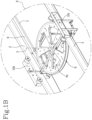
- the irrigation system 1 also comprises a recirculation wheel 8 slidable along the rails 2 following the irrigation carriage 3.
- the recirculation wheel 8 is configured to keep the primary hose 6 and the secondary hose 7 taught during a sliding of the irrigation carriage 3 between the first and the second end of the greenhouse. In other words, during both a forward movement along the movement path "D" and during a return movement along the movement path "D", the recirculation wheel 8 is configured to follow a predetermined distance the irrigation carriage 3 keeping constantly under tension the primary 6 and secondary 7 hoses.
- the recirculation wheel 8, as shown for example in the accompanying drawings, slides on the rails 2 by means of suitable sliding carriages 10b. A suitable support for the recirculation wheel 8 is mounted on the sliding carriage 10b.
- the recirculation wheel 8 is configured to rotate about its own axis of extension "S" during the sliding along the rails 2.
- the recirculation wheel 8 is equipped with bearings installed or which can be installed on the support of the recirculation wheel 8 to allow the rotation during the sliding along the rails 2.
- the recirculation wheel 8 defines a first sliding channel 8a and a second sliding channel 8b.
- the first sliding channel 8a is configured for receiving at least partly the primary hose 6.
- the second sliding channel 8b is configured for receiving at least partly the secondary hose 7.
- the first sliding channel 8a and the second sliding channel 8b are shaped in such a way as to receive and allow the sliding of the primary 6 and secondary 7 hoses in such a way as to keep them taught during a movement of the irrigation carriage 3 along the rails 2.
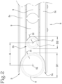
- first sliding channel 8a and the second sliding channel 8b accommodate, respectively, the primary hose 6 and the secondary hose 7 in such a way as to keep the sliding axes 6a and 7a of the primary hose 6 and of the secondary hose 7 parallel to each other and lying on a same sliding plane.
- the sliding axes 6a and 7a of the primary hose 6 and of the secondary hose 7 are parallel to each other and lie in the same horizontal sliding plane.
- this solution makes it possible to obtain a sliding without interference between the primary hose 6 and the secondary hose 7 which are kept in tension without the generation of jerks which could result in an oscillation of the at least one irrigation bar 4 (or irrigation bars 4) which would cause a non-optimum irrigation.
- the first sliding channel 8a and the second sliding channel 8b are spaced from each other by an axial distance "A" of 41 mm.
- Other dimensions of the axial distance "A” are possible.
- the axial distance "A” means the distance between the sliding axes 6a and 7a of the primary hose 6 and of the secondary hose 7.
- the axial distance "A” may coincide with the distance of the axes of extension of the first sliding channel 8a and of the second sliding channel 8b.
- the axes of extension of the sliding channels 8a and 8b coincide with the respective sliding axes 6a and 7a of the primary 6 and secondary 7 hoses.
- the axial distance "A" makes it possible to guarantee a detachment between the primary hose 6 and the secondary hose 7 when they slide received by the recirculation wheel 8 preventing them from sliding against each other and causing damage.
- the first sliding channel 8a is be-defined directly on an annular edge portion "B" of the recirculation wheel 8, whilst the second sliding channel 8b is defined inside the recirculation wheel 8.
- the recirculation wheel 8 is defined by two annular elements 8c facing each other.
- Each annular element 8c has an annular edge "B" suitable for forming a portion of the first sliding channel 8a.
- the edge "B" of each annular element 8c has an arched profile suitable for fitting at least partly around at least one portion of the primary hose 6.
- each annular element 8c has a curved shape suitable for forming the first sliding channel 8a.
- the first sliding channel 8a has the above-mentioned curved profile.
- the first sliding channel 8a is shaped to match at least a portion of the primary hose 6.
- the first sliding channel 8a has dimensions similar to those of the primary hose 6.
- the first sliding channel 8a has a diameter of 40 mm suitable for retaining a primary hose 6 with similar dimensions. Other dimensions of the diameter are possible.
- the second sliding channel 8b is defined in a space defined between the two facing annular elements 8c. In other words, the second sliding channel 8b is positioned between the two annular elements 8c and is therefore positioned inside the recirculation wheel 8.
- the second sliding channel 8b is defined by a plurality of pulleys 9 arranged radially inside the space defined by the two facing annular elements 8c.
- the pulleys 9 are positioned radially relative to the axis of extension "S" of the recirculation wheel 8 defining a circumference concentric to the edge "B" of the wheel 8 (that is, of the annular elements 8c).
- Each pulley 9 is free to rotate in such a way as to facilitate the sliding of the secondary hose 7 positioned inside the second sliding channel 8b defined by the pulleys 9.
- each pulley 9 is suitable for defining a portion of the second sliding channel 8b.
- Each pulley 9 has an arched profile suitable for fitting at least partly around at least one portion of the secondary hose 7. For this reason, each pulley 9 has a curved shape suitable for defining the second sliding channel 8b. In other words, the second sliding channel 8b has the above-mentioned curved profile.
- the second sliding channel 8b is shaped to match at least a portion of the secondary hose 7.
- the second sliding channel 8b has dimensions similar to those of the secondary hose 7.
- the second sliding channel 8b has a diameter of 20 mm suitable for retaining a secondary hose 7 with similar dimensions.
- the irrigation system 1 according to the invention is able to overcome the drawbacks of the prior art.
- the recirculation wheel 8 is shaped in such a way as to keep spaced from each other the primary 6 and secondary 7 hoses. In this way it is possible to prevent the two hoses from rubbing against each other causing jerks which would lead to unwanted movements of the irrigation bars 4.
- the recirculation wheel 8 makes it possible to avoid undesired damage and wear of the two hoses.
- the recirculation wheel 8 allows the two hoses to be effectively kept taught during a sliding of the irrigation carriage 3 along the movement path "D".
Landscapes
- Life Sciences & Earth Sciences (AREA)
- Environmental Sciences (AREA)
- Engineering & Computer Science (AREA)
- General Engineering & Computer Science (AREA)
- Mechanical Engineering (AREA)
- Catching Or Destruction (AREA)
Claims (9)
- Bewässerungssystem (1) für große Gewächshäuser, umfassend:- Schienen (2), die auf einer vorbestimmten Höhe eines Gewächshauses vorbereitet sind und sich von einem ersten Ende zu einem zweiten Ende entlang einer Hauptausdehnungsrichtung des Gewächshauses erstrecken;- einen Bewässerungswagen (3), der entlang der Schienen (2) zwischen dem ersten und dem zweiten Ende verschiebbar ist und mindestens eine Bewässerungsstange (4) umfasst, die mit geeigneten Düsen (5) ausgestattet ist, die ausgelegt sind, um Pflanzen zu bewässern, die in einem Abschnitt des Gewächshauses unter der Bewässerungsstange (4) befindlich sind;- einen Hauptschlauch (6), der mit dem Bewässerungswagen (3) verbunden ist oder werden kann und ausgelegt ist, um der mindestens einen Bewässerungsstange (4) ein Bewässerungsmedium zuzuführen;- einen Nebenschlauch (7), der mit dem Bewässerungswagen (3) verbunden ist oder werden kann, um der mindestens einen Bewässerungsstange (4) einen Zusatzstoff zuzuführen oder um den Bewässerungswagen (3) mit Strom zu versorgen;- ein Umlaufrad (8), das entlang der Schienen (2), dem Bewässerungswagen (3) folgend, verschiebbar und ausgelegt ist, um den Hauptschlauch (6) und den Nebenschlauch (7) während eines Verschiebens des Bewässerungswagens (3) zwischen dem ersten und zweiten Ende des Gewächshauses gespannt zu halten und einen ersten Verschiebekanal (8a) und einen zweiten Verschiebekanal (8b) zu definieren, die jeweils ausgelegt sind, um mindestens teilweise den Hauptschlauch (6) und den Nebenschlauch (7) aufzunehmen, sodass Verschiebeachsen (6a, 7a) des Hauptschlauchs (6) und des Nebenschlauchs (7) parallel zueinander und liegend auf einer selben Ebene beibehalten werden, dadurch gekennzeichnet, dass das Umlaufrad (8) einen ersten Verschiebekanal (8a) aufweist, der direkt auf einem ringförmigen Randabschnitt (B) des Umlaufrads (S) definiert ist, und wobei der zweite Verschiebekanal (8b) innerhalb des Umlaufrads (8) definiert ist.
- Bewässerungssystem (1) nach Anspruch 1, wobei das Umlaufrad (8) durch zwei ringförmige Elemente (8c), die einander zugewandt sind, definiert ist, ein jedes ringförmiges Element (8c) einen Rand (B) aufweist, der geeignet ist, um einen Abschnitt des ersten Verschiebekanals (8a) zu definieren, und wobei der zweite Verschiebekanal (8b) in einem Raum definiert ist, der zwischen den beiden einander zugewandten Elementen (8c) definiert ist.
- Bewässerungssystem (1) nach Anspruch 2, wobei der zweite Verschiebekanal (8b) durch eine Vielzahl von Rollen (9) definiert ist, die radial innerhalb des durch die beiden einander zugewandten ringförmigen Elemente (8c) definierten Raums angeordnet sind.
- Bewässerungssystem (1) nach einem der vorhergehenden Ansprüche, wobei der erste Verschiebekanal (8a) und der zweite Verschiebekanal (8b) ein gekrümmtes Profil aufweisen, um jeweils mindestens um einen Abschnitt des Hauptschlauchs (6) und des Nebenschlauchs (7) eingepasst zu werden.
- Bewässerungssystem (1) nach einem der vorhergehenden Ansprüche, wobei der erste Verschiebekanal (8a) und der zweite Verschiebekanal (8b) jeweils passend zum Hauptschlauch (6) und zum Nebenschlauch (7) ausgeformt sind.
- Bewässerungssystem (1) nach einem der vorhergehenden Ansprüche, wobei der Hauptschlauch (6) einen Durchmesser (D1) von 40 mm aufweist, und wobei der Nebenschlauch (7) einen Durchmesser (D2) von 20 mm aufweist.
- Bewässerungssystem (1) nach einem der vorhergehenden Ansprüche, wobei der erste Verschiebekanal (8a) und der zweite Verschiebekanal (8b) durch einen axialen Abstand (A) von 41 mm voneinander beabstandet sind.
- Bewässerungssystem (1) nach einem der vorhergehenden Ansprüche, wobei das Rad (8) ausgelegt ist, um sich während des Verschiebens entlang der Schienen (2) um eine relative Ausdehnungsachse (S) zu drehen.
- Bewässerungssystem (1) nach einem der vorhergehenden Ansprüche, wobei der Bewässerungswagen (3) zwei Bewässerungsstangen (4) umfasst, die gegenständig zueinander angeordnet und mit geeigneten Düsen (5) ausgestattet sind, die ausgelegt sind, um Pflanzen zu bewässern, die in einem Abschnitt unter einer jeden Bewässerungsstange (4) befindlich sind, wobei der Hauptschlauch (6) mit beiden Bewässerungsstangen (4) verbunden ist oder werden kann und der Nebenschlauch (7) mit beiden Bewässerungsstangen (4) verbunden ist oder werden kann.
Applications Claiming Priority (2)
| Application Number | Priority Date | Filing Date | Title |
|---|---|---|---|
| IT201900013977A IT201900013977A1 (de) | 2019-08-05 | 2019-08-05 | |
| PCT/IB2020/057313 WO2021024154A1 (en) | 2019-08-05 | 2020-08-03 | Recirculation wheel for irrigation systems. |
Publications (3)
| Publication Number | Publication Date |
|---|---|
| EP4009772A1 EP4009772A1 (de) | 2022-06-15 |
| EP4009772B1 true EP4009772B1 (de) | 2024-10-02 |
| EP4009772C0 EP4009772C0 (de) | 2024-10-02 |
Family
ID=69105978
Family Applications (1)
| Application Number | Title | Priority Date | Filing Date |
|---|---|---|---|
| EP20744219.5A Active EP4009772B1 (de) | 2019-08-05 | 2020-08-03 | Umlaufrad für bewässerungssysteme |
Country Status (4)
| Country | Link |
|---|---|
| US (1) | US20220248613A1 (de) |
| EP (1) | EP4009772B1 (de) |
| IT (1) | IT201900013977A1 (de) |
| WO (1) | WO2021024154A1 (de) |
Families Citing this family (5)
| Publication number | Priority date | Publication date | Assignee | Title |
|---|---|---|---|---|
| CN112320636B (zh) * | 2020-09-29 | 2023-01-10 | 安塔(福建)机械设备实业有限公司 | 一种建筑工地塔吊的洒水降尘装置 |
| US20240065182A1 (en) * | 2022-08-23 | 2024-02-29 | Hall Labs Llc | Grow System Stack |
| US20240065181A1 (en) * | 2022-08-23 | 2024-02-29 | Hall Labs Llc | Raisable Grow System |
| CN117617092B (zh) * | 2024-01-25 | 2024-04-09 | 山东省寿光蔬菜产业集团有限公司 | 一种口感型设施番茄精准调控灌溉装置 |
| CN120345482B (zh) * | 2025-06-12 | 2026-03-06 | 寿光市盛丰温室工程有限公司 | 一种蔬菜种植大棚智慧喷灌系统 |
Citations (1)
| Publication number | Priority date | Publication date | Assignee | Title |
|---|---|---|---|---|
| KR200444297Y1 (ko) * | 2008-10-29 | 2009-05-04 | 이규동 | 농업용 호오스 안내구 |
Family Cites Families (2)
| Publication number | Priority date | Publication date | Assignee | Title |
|---|---|---|---|---|
| US5344084A (en) * | 1993-01-11 | 1994-09-06 | Andpro Ltd. | Watering system for connection to a water supply and an electrical supply for use in watering plants and the like |
| KR101902826B1 (ko) * | 2015-09-10 | 2018-10-01 | 민성준 | 재배하우스의 레일방식 관수공급장치 |
-
2019
- 2019-08-05 IT IT201900013977A patent/IT201900013977A1/it unknown
-
2020
- 2020-08-03 EP EP20744219.5A patent/EP4009772B1/de active Active
- 2020-08-03 US US17/627,057 patent/US20220248613A1/en not_active Abandoned
- 2020-08-03 WO PCT/IB2020/057313 patent/WO2021024154A1/en not_active Ceased
Patent Citations (1)
| Publication number | Priority date | Publication date | Assignee | Title |
|---|---|---|---|---|
| KR200444297Y1 (ko) * | 2008-10-29 | 2009-05-04 | 이규동 | 농업용 호오스 안내구 |
Also Published As
| Publication number | Publication date |
|---|---|
| US20220248613A1 (en) | 2022-08-11 |
| EP4009772A1 (de) | 2022-06-15 |
| WO2021024154A1 (en) | 2021-02-11 |
| EP4009772C0 (de) | 2024-10-02 |
| IT201900013977A1 (de) | 2019-08-05 |
Similar Documents
| Publication | Publication Date | Title |
|---|---|---|
| US20220248613A1 (en) | Recirculation wheel for irrigation systems | |
| US8948979B2 (en) | Variable-speed irrigation system | |
| EP3772900B1 (de) | System zum besprühen von blatt- und wurzelbereichen von pflanzen | |
| KR101877534B1 (ko) | 식물재배 베드 장착용 분무 수경 플랫폼 조립체 | |
| AU2004246962A1 (en) | Hydraulic control valve for drip hoses | |
| EP3296385B1 (de) | Modulares system mit photobioreaktoren zum züchten von algen | |
| US9545063B1 (en) | Overhead irrigation assembly having three or more truss rods | |
| KR20170030765A (ko) | 재배하우스의 레일방식 관수공급장치 | |
| EP4149240B1 (de) | Aeroponisches anordnung | |
| KR20110069357A (ko) | 하우스용 무인방제기구 | |
| JP5749549B2 (ja) | 水耕栽培用定植板 | |
| KR20130063883A (ko) | 농업용 자동 이동식 급수장치 | |
| KR101651750B1 (ko) | 모판에 육묘를 위한 모판 자동 이송장치 | |
| KR20200048136A (ko) | 작물 재배 시스템 | |
| US20190098845A1 (en) | Dynamic planting grid assembly having internal watering system | |
| US10736279B2 (en) | Method and system for in row variable rate precision irrigation | |
| KR200481257Y1 (ko) | 다층작물재배장치 | |
| JP3197682U (ja) | 植物栽培補助装置、および、これに用いるパイプ、パイプ用バルブ | |
| WO2009048327A1 (en) | System, guide and method for the guiding of a plant | |
| KR102677814B1 (ko) | 호스 각도 조절장치 | |
| JP2015211658A (ja) | 植物栽培装置及びそれを備えた植物工場設備 | |
| JP7403890B1 (ja) | 散布装置 | |
| KR20160009205A (ko) | 비닐하우스용 액비살포장치 | |
| KR102820019B1 (ko) | 식물 재배 시설의 거터 이송 시스템 및 상기 식물 재배 시설의 거터 이송 시스템에 적용된 거터 이송 유닛 | |
| KR20210022614A (ko) | 식물재배시스템의 온실 |
Legal Events
| Date | Code | Title | Description |
|---|---|---|---|
| STAA | Information on the status of an ep patent application or granted ep patent |
Free format text: STATUS: UNKNOWN |
|
| STAA | Information on the status of an ep patent application or granted ep patent |
Free format text: STATUS: THE INTERNATIONAL PUBLICATION HAS BEEN MADE |
|
| PUAI | Public reference made under article 153(3) epc to a published international application that has entered the european phase |
Free format text: ORIGINAL CODE: 0009012 |
|
| STAA | Information on the status of an ep patent application or granted ep patent |
Free format text: STATUS: REQUEST FOR EXAMINATION WAS MADE |
|
| 17P | Request for examination filed |
Effective date: 20220201 |
|
| AK | Designated contracting states |
Kind code of ref document: A1 Designated state(s): AL AT BE BG CH CY CZ DE DK EE ES FI FR GB GR HR HU IE IS IT LI LT LU LV MC MK MT NL NO PL PT RO RS SE SI SK SM TR |
|
| DAV | Request for validation of the european patent (deleted) | ||
| DAX | Request for extension of the european patent (deleted) | ||
| GRAP | Despatch of communication of intention to grant a patent |
Free format text: ORIGINAL CODE: EPIDOSNIGR1 |
|
| STAA | Information on the status of an ep patent application or granted ep patent |
Free format text: STATUS: GRANT OF PATENT IS INTENDED |
|
| RIC1 | Information provided on ipc code assigned before grant |
Ipc: F16L 3/01 20060101ALI20240321BHEP Ipc: A01G 25/09 20060101ALI20240321BHEP Ipc: A01G 9/24 20060101AFI20240321BHEP |
|
| INTG | Intention to grant announced |
Effective date: 20240422 |
|
| GRAS | Grant fee paid |
Free format text: ORIGINAL CODE: EPIDOSNIGR3 |
|
| GRAA | (expected) grant |
Free format text: ORIGINAL CODE: 0009210 |
|
| STAA | Information on the status of an ep patent application or granted ep patent |
Free format text: STATUS: THE PATENT HAS BEEN GRANTED |
|
| AK | Designated contracting states |
Kind code of ref document: B1 Designated state(s): AL AT BE BG CH CY CZ DE DK EE ES FI FR GB GR HR HU IE IS IT LI LT LU LV MC MK MT NL NO PL PT RO RS SE SI SK SM TR |
|
| REG | Reference to a national code |
Ref country code: GB Ref legal event code: FG4D |
|
| REG | Reference to a national code |
Ref country code: CH Ref legal event code: EP |
|
| REG | Reference to a national code |
Ref country code: IE Ref legal event code: FG4D |
|
| REG | Reference to a national code |
Ref country code: DE Ref legal event code: R096 Ref document number: 602020038693 Country of ref document: DE |
|
| U01 | Request for unitary effect filed |
Effective date: 20241023 |
|
| U07 | Unitary effect registered |
Designated state(s): AT BE BG DE DK EE FI FR IT LT LU LV MT NL PT RO SE SI Effective date: 20241106 |
|
| PG25 | Lapsed in a contracting state [announced via postgrant information from national office to epo] |
Ref country code: HR Free format text: LAPSE BECAUSE OF FAILURE TO SUBMIT A TRANSLATION OF THE DESCRIPTION OR TO PAY THE FEE WITHIN THE PRESCRIBED TIME-LIMIT Effective date: 20241002 Ref country code: IS Free format text: LAPSE BECAUSE OF FAILURE TO SUBMIT A TRANSLATION OF THE DESCRIPTION OR TO PAY THE FEE WITHIN THE PRESCRIBED TIME-LIMIT Effective date: 20250202 |
|
| PG25 | Lapsed in a contracting state [announced via postgrant information from national office to epo] |
Ref country code: ES Free format text: LAPSE BECAUSE OF FAILURE TO SUBMIT A TRANSLATION OF THE DESCRIPTION OR TO PAY THE FEE WITHIN THE PRESCRIBED TIME-LIMIT Effective date: 20241002 |
|
| PG25 | Lapsed in a contracting state [announced via postgrant information from national office to epo] |
Ref country code: NO Free format text: LAPSE BECAUSE OF FAILURE TO SUBMIT A TRANSLATION OF THE DESCRIPTION OR TO PAY THE FEE WITHIN THE PRESCRIBED TIME-LIMIT Effective date: 20250102 |
|
| PG25 | Lapsed in a contracting state [announced via postgrant information from national office to epo] |
Ref country code: GR Free format text: LAPSE BECAUSE OF FAILURE TO SUBMIT A TRANSLATION OF THE DESCRIPTION OR TO PAY THE FEE WITHIN THE PRESCRIBED TIME-LIMIT Effective date: 20250103 |
|
| PG25 | Lapsed in a contracting state [announced via postgrant information from national office to epo] |
Ref country code: CZ Free format text: LAPSE BECAUSE OF FAILURE TO SUBMIT A TRANSLATION OF THE DESCRIPTION OR TO PAY THE FEE WITHIN THE PRESCRIBED TIME-LIMIT Effective date: 20241002 Ref country code: PL Free format text: LAPSE BECAUSE OF FAILURE TO SUBMIT A TRANSLATION OF THE DESCRIPTION OR TO PAY THE FEE WITHIN THE PRESCRIBED TIME-LIMIT Effective date: 20241002 |
|
| PG25 | Lapsed in a contracting state [announced via postgrant information from national office to epo] |
Ref country code: RS Free format text: LAPSE BECAUSE OF FAILURE TO SUBMIT A TRANSLATION OF THE DESCRIPTION OR TO PAY THE FEE WITHIN THE PRESCRIBED TIME-LIMIT Effective date: 20250102 |
|
| PG25 | Lapsed in a contracting state [announced via postgrant information from national office to epo] |
Ref country code: SM Free format text: LAPSE BECAUSE OF FAILURE TO SUBMIT A TRANSLATION OF THE DESCRIPTION OR TO PAY THE FEE WITHIN THE PRESCRIBED TIME-LIMIT Effective date: 20241002 |
|
| PG25 | Lapsed in a contracting state [announced via postgrant information from national office to epo] |
Ref country code: SK Free format text: LAPSE BECAUSE OF FAILURE TO SUBMIT A TRANSLATION OF THE DESCRIPTION OR TO PAY THE FEE WITHIN THE PRESCRIBED TIME-LIMIT Effective date: 20241002 |
|
| PLBE | No opposition filed within time limit |
Free format text: ORIGINAL CODE: 0009261 |
|
| STAA | Information on the status of an ep patent application or granted ep patent |
Free format text: STATUS: NO OPPOSITION FILED WITHIN TIME LIMIT |
|
| 26N | No opposition filed |
Effective date: 20250703 |
|
| U20 | Renewal fee for the european patent with unitary effect paid |
Year of fee payment: 6 Effective date: 20250806 |
|
| PGFP | Annual fee paid to national office [announced via postgrant information from national office to epo] |
Ref country code: GB Payment date: 20251125 Year of fee payment: 6 |
|
| REG | Reference to a national code |
Ref country code: CH Ref legal event code: H13 Free format text: ST27 STATUS EVENT CODE: U-0-0-H10-H13 (AS PROVIDED BY THE NATIONAL OFFICE) Effective date: 20260324 |
|
| PG25 | Lapsed in a contracting state [announced via postgrant information from national office to epo] |
Ref country code: MC Free format text: LAPSE BECAUSE OF FAILURE TO SUBMIT A TRANSLATION OF THE DESCRIPTION OR TO PAY THE FEE WITHIN THE PRESCRIBED TIME-LIMIT Effective date: 20241002 |
|
| PG25 | Lapsed in a contracting state [announced via postgrant information from national office to epo] |
Ref country code: CH Free format text: LAPSE BECAUSE OF NON-PAYMENT OF DUE FEES Effective date: 20250831 |
|
| PG25 | Lapsed in a contracting state [announced via postgrant information from national office to epo] |
Ref country code: IE Free format text: LAPSE BECAUSE OF NON-PAYMENT OF DUE FEES Effective date: 20250803 |