EP4009843B1 - Dispositif de compensation des variations de pression - Google Patents
Dispositif de compensation des variations de pression Download PDFInfo
- Publication number
- EP4009843B1 EP4009843B1 EP20746190.6A EP20746190A EP4009843B1 EP 4009843 B1 EP4009843 B1 EP 4009843B1 EP 20746190 A EP20746190 A EP 20746190A EP 4009843 B1 EP4009843 B1 EP 4009843B1
- Authority
- EP
- European Patent Office
- Prior art keywords
- separating element
- vacuum cleaner
- base body
- compensating
- air
- Prior art date
- Legal status (The legal status is an assumption and is not a legal conclusion. Google has not performed a legal analysis and makes no representation as to the accuracy of the status listed.)
- Active
Links
Images



Classifications
-
- B—PERFORMING OPERATIONS; TRANSPORTING
- B01—PHYSICAL OR CHEMICAL PROCESSES OR APPARATUS IN GENERAL
- B01D—SEPARATION
- B01D46/00—Filters or filtering processes specially modified for separating dispersed particles from gases or vapours
-
- A—HUMAN NECESSITIES
- A47—FURNITURE; DOMESTIC ARTICLES OR APPLIANCES; COFFEE MILLS; SPICE MILLS; SUCTION CLEANERS IN GENERAL
- A47L—DOMESTIC WASHING OR CLEANING; SUCTION CLEANERS IN GENERAL
- A47L9/00—Details or accessories of suction cleaners, e.g. mechanical means for controlling the suction or for effecting pulsating action; Storing devices specially adapted to suction cleaners or parts thereof; Carrying-vehicles specially adapted for suction cleaners
- A47L9/0072—Mechanical means for controlling the suction or for effecting pulsating action
-
- A—HUMAN NECESSITIES
- A47—FURNITURE; DOMESTIC ARTICLES OR APPLIANCES; COFFEE MILLS; SPICE MILLS; SUCTION CLEANERS IN GENERAL
- A47L—DOMESTIC WASHING OR CLEANING; SUCTION CLEANERS IN GENERAL
- A47L9/00—Details or accessories of suction cleaners, e.g. mechanical means for controlling the suction or for effecting pulsating action; Storing devices specially adapted to suction cleaners or parts thereof; Carrying-vehicles specially adapted for suction cleaners
- A47L9/20—Means for cleaning filters
-
- A—HUMAN NECESSITIES
- A47—FURNITURE; DOMESTIC ARTICLES OR APPLIANCES; COFFEE MILLS; SPICE MILLS; SUCTION CLEANERS IN GENERAL
- A47L—DOMESTIC WASHING OR CLEANING; SUCTION CLEANERS IN GENERAL
- A47L9/00—Details or accessories of suction cleaners, e.g. mechanical means for controlling the suction or for effecting pulsating action; Storing devices specially adapted to suction cleaners or parts thereof; Carrying-vehicles specially adapted for suction cleaners
- A47L9/24—Hoses or pipes; Hose or pipe couplings
- A47L9/248—Parts, details or accessories of hoses or pipes
-
- B—PERFORMING OPERATIONS; TRANSPORTING
- B08—CLEANING
- B08B—CLEANING IN GENERAL; PREVENTION OF FOULING IN GENERAL
- B08B13/00—Accessories or details of general applicability for machines or apparatus for cleaning
-
- B—PERFORMING OPERATIONS; TRANSPORTING
- B08—CLEANING
- B08B—CLEANING IN GENERAL; PREVENTION OF FOULING IN GENERAL
- B08B5/00—Cleaning by methods involving the use of air flow or gas flow
- B08B5/04—Cleaning by suction, with or without auxiliary action
-
- A—HUMAN NECESSITIES
- A47—FURNITURE; DOMESTIC ARTICLES OR APPLIANCES; COFFEE MILLS; SPICE MILLS; SUCTION CLEANERS IN GENERAL
- A47L—DOMESTIC WASHING OR CLEANING; SUCTION CLEANERS IN GENERAL
- A47L7/00—Suction cleaners adapted for additional purposes; Tables with suction openings for cleaning purposes; Containers for cleaning articles by suction; Suction cleaners adapted to cleaning of brushes; Suction cleaners adapted to taking-up liquids
- A47L7/0095—Suction cleaners or attachments adapted to collect dust or waste from power tools
Definitions
- the present invention relates to a device for a vacuum cleaner for compensating for air pressure fluctuations, having a base body through which an air flow can flow in one flow direction.
- the present invention relates to a vacuum cleaner hose with at least one device for a vacuum cleaner to compensate for air pressure fluctuations.
- Prior art vacuum cleaners which are used in connection with a dust-generating machine tool, in particular rotary hammers, grinders or saws, usually have a filter cleaning system for occasional cleaning of the filter in the vacuum cleaner.
- the function of the filter is maintained by occasional cleaning.
- the filter is cleaned by means of a sudden, brief reversal of the pressure conditions in front of and behind the filter, which reverses the normal air flow through the filter to be cleaned.
- the air flow which flows against the usual flow direction, causes the accumulated dust and dirt to fall out of the filter into a storage container in the form of a pressure surge, so that the filter is then free again and thus has an improved filter effect.
- this causes a pressure fluctuation in the suction system.
- the FR 1 189 789 A a vacuum regulator for a vacuum cleaner, the vacuum regulator being arranged in an air line between the blower and the suction opening and being formed from two tube sections which can be slid into one another.
- a passage opening, which can be covered by an axial displacement of the other pipe section, is to be arranged in a casing of one pipe section.
- no indication can be found as to how a negative pressure is maintained in the vacuum cleaner in such a way that sufficiently good suction of dust can also be made possible while the filters are being cleaned.
- the object is achieved by a device for a vacuum cleaner for compensating for air pressure fluctuations with a base body through which an air flow can flow in one flow direction.
- the base body contains at least one passage opening and a separating element is contained for separating the passage opening from ambient air, the separating element being movable so that a reservoir for taking up a volume of air is generated between the base body and the separating element and a negative pressure generated by the air flow in the base body at least partially preserved.
- the separating element may be designed in the form of an elastic membrane.
- a separating element can be created in a simple manner, which abuts with a precise shape on an outer wall of the base body and, on the other hand, can produce a reservoir shape that is as variable as possible.
- the separating element can also be possible for the separating element to be designed in the form of a piston-cylinder unit.
- a separating element that is as stable as possible can be created, which is largely resistant to mechanical influences (such as impacts or blows) and ensures reliable functionality.
- the separating element may be designed in the form of a plate that can be pivoted away from the base body.
- the pivotable plate can also be referred to as pivotable or rotatable (in the sense of rotatable).
- a separating element that is as stable as possible can also be created.
- the design of the separating element in the form of a swing-away plate only has to be attached to the base body with just one hinge element, so that in contrast to the design as a piston-cylinder unit, a lower fitting accuracy is required.
- the freely pivoting end of the designed as a pivotable plate separating element can with a membrane so at the Be attached to the outer wall of the base body that an airtight seal is formed between the freely pivoting end of the separating element and the outer wall of the base body.
- the configuration as a pivotable plate ensures a certain robustness against dust penetrating into the device.
- the separating element can be designed in the form of a bellows.
- a vacuum cleaner hose with at least one device for a vacuum cleaner for compensating for air pressure fluctuations with a base body through which an air flow can flow in a flow direction.
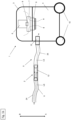
- Figure 1a and 1b show a vacuum cleaner 1 with a device 2 for compensating for air pressure fluctuations according to a first embodiment.
- the vacuum cleaner 1 essentially contains a suction head 3, a storage container 4 and a suction device 5.
- the suction head 3 essentially contains a filter 6, a filter cleaning device 7 and a turbine 8.
- the turbine 8 serves to generate a negative pressure through which an air flow LS flows into the interior of the vacuum cleaner 1 . With the help of this air flow LS, dust particles and dirt particles can be sucked up and conveyed into the storage container 4 for storage.
- the filter 6 serves to filter out dust and dirt particles from an air flow LS sucked in by the vacuum cleaner 1 and thus protects, among other things, the turbine 8 from dust and dirt.
- the filter cleaning device 7 is designed to reverse the pressure conditions in the flow direction HS in front of and behind the filter 6 for a short time and abruptly. In other words: the air flow LS in direction B in direction A reversed. An air pressure surge generated in this way leads to a cleaning of the filter 6 , as a result of which the dust and dirt collected in the filter 6 falls in direction B and into the storage container 4 . As a result, the filter 6 is free and functional again. The air flow LS is then restored along the flow direction HS with the aid of the filter cleaning device 7 .
- the function and in particular the changeover of the filter cleaning device 7 is controlled by a control device 9 .
- the storage container 4 is essentially designed as a container with a capacity. On the underside of the storage container 4 configured as a container, wheels 10 are provided for the mobility of the vacuum cleaner. Only two wheels 10 are shown in the figures.
- the suction device 5 essentially contains a vacuum cleaner hose 11, a fastening element 12 and a nozzle.
- the nozzle can be a floor nozzle, for example. The nozzle is not shown in the figures.
- the fastening element 12 is designed essentially as a cylindrical tube and serves as an interface or connection for the vacuum cleaner hose 11 on the storage container 4.
- FIG 4 and 5 shows the device 2 for compensating for air pressure fluctuations according to a first embodiment.
- the device 2 essentially contains a base body 13 and a separating element 14.
- the base body 13 is designed essentially as a tube-like cylinder with a waisted area TB.
- the base body 13 thus contains a first area 15 and second area 16 with a first flow cross-sectional area 17 and a third area 18 with a second flow cross-sectional area 19.
- the third area 18 is positioned between the first and second areas 15,16.
- the transition 20 from the first area 15 to the third area 18 and the transition 21 from the second area 16 to the third area 18 are each designed in the shape of a truncated cone.
- the base body 13 contains a number of through-openings 22 over the entire length L.
- the through-openings 22 can also be referred to as through-holes. Air can flow from the interior of the base body 13 to the outside and from the outside into the interior of the base body 13 through the passage openings 22 .
- the separating element 14 is designed in the form of a tube made of an elastic membrane, cf. figure 4 and 5 .
- the separating element 14 designed as a membrane encloses the area of the base body 13 which has the through-openings 22 .
- the separating element 14 thus extends from the first area 15 to the second area 16 of the base body 13.
- a multiplicity of elevations are arranged in a radial orientation on the outer wall AW of the base body 13 .
- the elevations are not shown in the figures.
- the elevations can be designed as ribs.
- the elevations serve to ensure that during the normal suction process, the separating element 14 designed as a membrane rests tangentially only on the elevations and the remaining outer wall AW of the base body 13 is not covered by the separating element 14 . It is possible that the through-openings 22 are only positioned at the upper ends of the elevations. As a result, during the normal suction process, the separating element 14 designed as a membrane is sucked onto the base body 13 only in the areas of the elevations.
- an air flow LS flows in a flow direction HS from the floor nozzle (not shown) via the vacuum cleaner hose 11 through the device 2 for compensating for air pressure fluctuations, the storage container 4, the filter 6, the turbine 8 and through (Not shown) outflow openings out of the suction head 3 again.
- this sucks out dust and dirt particles.
- the airflow LS flows from a second end 16 of the base body 13 along the base body 13 to a first end 15 of the base body 13 (cf. figure 4 ).
- the separating element 14 which is designed as an elastic membrane, is sucked onto the outer wall AW of the base body 13 by the negative pressure generated by the air flow LS, so that the separating element 14 is tight against the outer wall AW of the base body 13 and thereby covers the through-openings 22 .
- the separating element 14 is in a first position, cf. Figure 1a and 4 .
- the air flow LS is not significantly impaired and dust continues to be sucked into the vacuum cleaner 1 with the aid of the air flow LS.
- Figure 1b shows the vacuum cleaner 1 in a filter cleaning mode, with which the filter 6 (as described above) is freed from the sucked dust and dirt.
- a pressure surge for cleaning the filter 6 is generated by briefly reversing the pressure conditions upstream and downstream of the filter 6 .
- the cleaning of the filter 6 in this way can impair the negative pressure in the suction device 5 and in particular in the vacuum hose 11 .
- the negative pressure in the suction device 5 and in particular in the vacuum cleaner hose 11 is maintained in order to enable an uninterrupted suction process.
- the separating element 14 designed as an elastic membrane reduces its pretension and moves from the outer wall AW of the base body 13 in the radial direction.
- the separating element 14 thus moves radially from the first position (cf. Figure 1a and 4 ) to the second position (cf. Figure 1b and 5 ).
- the movement of the separating element 14 takes place as a result of the pressure difference between the still relatively low air pressure inside the base body 13 and the atmospheric air pressure of the ambient air UL around the base body 13.
- a reservoir 23 for receiving a volume of air LV is created between the base body 13 and the separating element 14 .
- the negative pressure generated by the air flow LS in the base body 13 is thus at least partially maintained and the suction process is continued.
- FIG. 1a and 1b shows Figure 1a and 1b the first embodiment of the vacuum cleaner hose 11 according to the invention, wherein the device 2 for compensating for air pressure fluctuations is positioned between a first hose section 24 and a second hose section 25 .
- the two hose sections 24, 25 are essentially of the same length.
- figure 2 shows a second embodiment of the vacuum cleaner hose 11 according to the invention, the device for compensating for air pressure fluctuations being positioned between a first hose section 24 and a second hose section 25 .
- the first hose section 24 is longer than the second hose section 25.
- figure 3 shows a third embodiment of the vacuum cleaner hose 11 according to the invention, wherein the device 2 for compensating for air pressure fluctuations is positioned directly on the fastening element 12 for the storage container 4. There is therefore only one hose section.
- Figure 6a shows a further embodiment of the device 2 for compensating for air pressure fluctuations, in which the separating element 14 is designed essentially as a piston-cylinder unit.
- the separating element 14 designed as a piston-cylinder unit is connected to the interior of the base body 13 through a through opening 22 such that an air volume LV can flow in direction B from the interior of the base body 13 into the cylinder 26 .
- the pressure difference between the air pressure inside the base body 13 and the ambient air UL ensures that the piston 27 is pressed in direction B.
- the reservoir 23 for receiving an air volume LV between the base body 13 and the separating element 14 is produced in the cylinder 26 .
- Openings 28 are provided at an upper end 26a of the cylinder 26 so that the area in direction B above the piston 27 is filled with ambient air UL and an atmospheric air pressure.
- Figure 6b shows a further embodiment of the device 2 for compensating for air pressure fluctuations, in which the separating element 14, as in the embodiment in Figure 6a , Is designed essentially as a piston-cylinder unit.
- the through hole 22 closed between the base body 13 and the separating element 14 by an elastic closure element 29 .
- the device 2 for compensating for air pressure fluctuations is positioned inside the storage container 4 .
Landscapes
- Engineering & Computer Science (AREA)
- Mechanical Engineering (AREA)
- Chemical & Material Sciences (AREA)
- Chemical Kinetics & Catalysis (AREA)
- Filtering Of Dispersed Particles In Gases (AREA)
- Electric Vacuum Cleaner (AREA)
- Filters For Electric Vacuum Cleaners (AREA)
Claims (6)
- Dispositif (2) destiné à un aspirateur (1) pour compenser les fluctuations de pression d'air, ledit dispositif comprenant un corps de base (13) qu'un écoulement d'air (LS) peut traverser dans un sens d'écoulement (HS),
caractérisé en ce que le corps de base (13) contient au moins une ouverture de passage (22) et en ce qu'un élément de séparation (14) est prévu pour séparer l'ouverture de passage (22) de l'air ambiant (UL), l'élément de séparation (14) étant mobile de sorte qu'un réservoir (23) destiné à recevoir un volume d'air (LV) soit généré entre le corps de base (13) et l'élément de séparation (14) et qu'une pression négative générée par l'écoulement d'air (LS) soit au moins partiellement maintenue dans le corps de base (13). - Dispositif (2) selon la revendication 1,
caractérisé en ce que l'élément de séparation (14) est conçu sous la forme d'une membrane élastique. - Dispositif (2) selon la revendication 1,
caractérisé en ce que l'élément de séparation (14) est conçu sous la forme d'une unité piston-cylindre. - Dispositif (2) selon la revendication 1,
caractérisé en ce que l'élément de séparation (14) est conçu sous la forme d'une plaque qui peut être écartée du corps de base (13) par pivotement. - Dispositif (2) selon l'une au moins des revendications 1 à 4,
caractérisé en ce qu'il est prévu plus d'un corps de base (13). - Tuyau d'aspirateur (11) comprenant au moins un dispositif (2) selon l'une au moins des revendications 1 à 5.
Applications Claiming Priority (2)
| Application Number | Priority Date | Filing Date | Title |
|---|---|---|---|
| EP19189940.0A EP3772310A1 (fr) | 2019-08-05 | 2019-08-05 | Dispositif de compensation des variations de pression |
| PCT/EP2020/070971 WO2021023525A1 (fr) | 2019-08-05 | 2020-07-24 | Dispositif de compensation de variations de pression |
Publications (2)
| Publication Number | Publication Date |
|---|---|
| EP4009843A1 EP4009843A1 (fr) | 2022-06-15 |
| EP4009843B1 true EP4009843B1 (fr) | 2023-05-31 |
Family
ID=67544087
Family Applications (2)
| Application Number | Title | Priority Date | Filing Date |
|---|---|---|---|
| EP19189940.0A Withdrawn EP3772310A1 (fr) | 2019-08-05 | 2019-08-05 | Dispositif de compensation des variations de pression |
| EP20746190.6A Active EP4009843B1 (fr) | 2019-08-05 | 2020-07-24 | Dispositif de compensation des variations de pression |
Family Applications Before (1)
| Application Number | Title | Priority Date | Filing Date |
|---|---|---|---|
| EP19189940.0A Withdrawn EP3772310A1 (fr) | 2019-08-05 | 2019-08-05 | Dispositif de compensation des variations de pression |
Country Status (6)
| Country | Link |
|---|---|
| US (1) | US12185901B2 (fr) |
| EP (2) | EP3772310A1 (fr) |
| JP (1) | JP7383056B2 (fr) |
| CN (1) | CN113924154B (fr) |
| DK (1) | DK4009843T3 (fr) |
| WO (1) | WO2021023525A1 (fr) |
Family Cites Families (20)
| Publication number | Priority date | Publication date | Assignee | Title |
|---|---|---|---|---|
| NL101886C (fr) | 1957-01-18 | |||
| US3545465A (en) | 1967-11-29 | 1970-12-08 | Vapor Corp | Pressure regulator |
| JPS5595637U (fr) * | 1978-12-22 | 1980-07-02 | ||
| FR2596171B1 (fr) | 1986-03-20 | 1988-12-02 | Francel Sa | Dispositif de maintien de la pression dans une canalisation a l'aval d'un poste de detente de gaz alimentant une utilisation tout ou rien |
| JPH0433443Y2 (fr) * | 1987-09-14 | 1992-08-11 | ||
| US4961245A (en) * | 1990-02-05 | 1990-10-09 | Ryobi Motor Products Corp. | Suction controlling arrangement in a canister vacuum cleaner |
| JP2563857Y2 (ja) * | 1991-04-22 | 1998-02-25 | エヌオーケー株式会社 | アキュムレータ |
| JPH1176202A (ja) | 1997-09-10 | 1999-03-23 | Isao Nishi | 安定同位体呼気ガス採取方法およびそれに使用するための装置 |
| FR2871396B1 (fr) | 2004-06-11 | 2006-09-15 | David Weill | Dispositif simplifie de nettoyage et remplissage avec piston |
| JP2006102031A (ja) * | 2004-10-04 | 2006-04-20 | Matsushita Electric Ind Co Ltd | 電気掃除機 |
| DE102005017702A1 (de) * | 2005-04-11 | 2006-10-12 | Alfred Kärcher Gmbh & Co. Kg | Verfahren zum Abreinigen der Filter eines Staubsaugers sowie Staubsauger zur Durchführung des Verfahrens |
| DE102010045979A1 (de) * | 2010-09-18 | 2012-03-22 | Nilfisk-Advance A/S | Filterabreinigung für Schmutzsauger mit externem Gebläse |
| CN203178824U (zh) | 2013-02-25 | 2013-09-04 | 长缆电工科技股份有限公司 | 对密闭容器中气体压力变化进行补偿的装置及均压装置 |
| EP2871399A1 (fr) | 2013-11-11 | 2015-05-13 | Nordson Corporation | Tampon de fluide en boucle fermée pour un système de mélange à deux composants monté pour déplacement avec un distributeur |
| EP2937031A1 (fr) * | 2014-04-23 | 2015-10-28 | HILTI Aktiengesellschaft | Changement de modes |
| DE102014110940A1 (de) * | 2014-08-01 | 2016-02-04 | Vorwerk & Co. Interholding Gmbh | Rückspülbarer Luftfilter |
| CN205481895U (zh) | 2016-01-11 | 2016-08-17 | 长乐太平洋食品有限公司 | 一种活塞式制冷系统 |
| CN206234089U (zh) | 2016-11-29 | 2017-06-09 | 河北钢铁集团矿业有限公司 | 矿用压缩机空气稳压装置 |
| CN208313824U (zh) | 2018-05-23 | 2019-01-01 | 盘锦鑫百联自动控制有限公司 | 一种石油天然气在线分析仪 |
| CN108895160B (zh) | 2018-07-20 | 2024-03-15 | 江苏大明生物工程装备有限公司 | 一种压力可调的压力容器 |
-
2019
- 2019-08-05 EP EP19189940.0A patent/EP3772310A1/fr not_active Withdrawn
-
2020
- 2020-07-24 US US17/632,713 patent/US12185901B2/en active Active
- 2020-07-24 CN CN202080041537.6A patent/CN113924154B/zh active Active
- 2020-07-24 WO PCT/EP2020/070971 patent/WO2021023525A1/fr not_active Ceased
- 2020-07-24 DK DK20746190.6T patent/DK4009843T3/da active
- 2020-07-24 JP JP2021572361A patent/JP7383056B2/ja active Active
- 2020-07-24 EP EP20746190.6A patent/EP4009843B1/fr active Active
Also Published As
| Publication number | Publication date |
|---|---|
| JP2022535573A (ja) | 2022-08-09 |
| US12185901B2 (en) | 2025-01-07 |
| US20220280003A1 (en) | 2022-09-08 |
| DK4009843T3 (da) | 2023-06-26 |
| CN113924154A (zh) | 2022-01-11 |
| WO2021023525A1 (fr) | 2021-02-11 |
| EP3772310A1 (fr) | 2021-02-10 |
| CN113924154B (zh) | 2022-11-22 |
| JP7383056B2 (ja) | 2023-11-17 |
| EP4009843A1 (fr) | 2022-06-15 |
Similar Documents
| Publication | Publication Date | Title |
|---|---|---|
| EP3644816B1 (fr) | Nettoyage de filtre | |
| EP2979602B1 (fr) | Filtre a air a retrolavage | |
| DE3113913A1 (de) | Vorrichtung zum auffangen von bohrmehl an der bohrstelle eines bohrers | |
| DE102015108558A1 (de) | Luftfilter | |
| EP0873075B1 (fr) | Dispositif d'aspiration a des fins de nettoyage | |
| DE102016118807A1 (de) | Rückspülbarer Luftfilter und Staubsauger mit einem rückspülbaren Luftfilter | |
| EP3730024B1 (fr) | Procédé de commande d'un procédé de nettoyage dans un dispositif d'aspiration des poussières et dispositif d'aspiration des poussières | |
| EP4009843B1 (fr) | Dispositif de compensation des variations de pression | |
| DE102016119194A1 (de) | Staubsauger mit einem Filterelement | |
| EP3296058A2 (fr) | Dispositif de nettoyage du trou de forage | |
| EP3462160B1 (fr) | Dispositif de purge pour filtre d'un système d'échantillonnage | |
| EP4009845B1 (fr) | Dispositif de compensation des surpressions au coup de bélier | |
| DE3041547C2 (fr) | ||
| WO2022063586A1 (fr) | Dispositif de filtration pour aspirateur et procédé de nettoyage de filtre | |
| DE102006023747B4 (de) | Pumpe zur Reinigung eines Bohrloches | |
| EP3199081B1 (fr) | Manchon a entree parallele | |
| WO2017097698A1 (fr) | Dispositif de connexion | |
| DE202006017585U1 (de) | Absaugeinrichtung für ein motorisch angetriebenes Handwerkzeuggerät | |
| DE102022209324A1 (de) | Schwingungsdämpfer | |
| DE69815484T2 (de) | Saugvorrichtung zum Halten von Nieten in einem Nietwerkzeug | |
| DE202006008092U1 (de) | Pumpe zur Reinigung eines Bohrloches | |
| EP2965679B1 (fr) | Tuyau d'aspiration pour un aspirateur et aspirateur dote d'un tel tuyau d'aspiration | |
| DE102023123077A1 (de) | Schalteinrichtung für eine Staubsaugvorrichtung und Staubsaugvorrichtung | |
| DE202004002431U1 (de) | Aufbau eines Staubsaugers mit einer Luftpumpe | |
| DE202009011069U1 (de) | Saug-/Blasgerät für Laub o.dgl. Gut mit Adapterstücken |
Legal Events
| Date | Code | Title | Description |
|---|---|---|---|
| STAA | Information on the status of an ep patent application or granted ep patent |
Free format text: STATUS: UNKNOWN |
|
| STAA | Information on the status of an ep patent application or granted ep patent |
Free format text: STATUS: THE INTERNATIONAL PUBLICATION HAS BEEN MADE |
|
| PUAI | Public reference made under article 153(3) epc to a published international application that has entered the european phase |
Free format text: ORIGINAL CODE: 0009012 |
|
| STAA | Information on the status of an ep patent application or granted ep patent |
Free format text: STATUS: REQUEST FOR EXAMINATION WAS MADE |
|
| 17P | Request for examination filed |
Effective date: 20220307 |
|
| AK | Designated contracting states |
Kind code of ref document: A1 Designated state(s): AL AT BE BG CH CY CZ DE DK EE ES FI FR GB GR HR HU IE IS IT LI LT LU LV MC MK MT NL NO PL PT RO RS SE SI SK SM TR |
|
| DAV | Request for validation of the european patent (deleted) | ||
| DAX | Request for extension of the european patent (deleted) | ||
| GRAP | Despatch of communication of intention to grant a patent |
Free format text: ORIGINAL CODE: EPIDOSNIGR1 |
|
| STAA | Information on the status of an ep patent application or granted ep patent |
Free format text: STATUS: GRANT OF PATENT IS INTENDED |
|
| INTG | Intention to grant announced |
Effective date: 20230315 |
|
| GRAS | Grant fee paid |
Free format text: ORIGINAL CODE: EPIDOSNIGR3 |
|
| GRAA | (expected) grant |
Free format text: ORIGINAL CODE: 0009210 |
|
| STAA | Information on the status of an ep patent application or granted ep patent |
Free format text: STATUS: THE PATENT HAS BEEN GRANTED |
|
| AK | Designated contracting states |
Kind code of ref document: B1 Designated state(s): AL AT BE BG CH CY CZ DE DK EE ES FI FR GB GR HR HU IE IS IT LI LT LU LV MC MK MT NL NO PL PT RO RS SE SI SK SM TR |
|
| REG | Reference to a national code |
Ref country code: GB Ref legal event code: FG4D Free format text: NOT ENGLISH Ref country code: CH Ref legal event code: EP |
|
| REG | Reference to a national code |
Ref country code: AT Ref legal event code: REF Ref document number: 1570469 Country of ref document: AT Kind code of ref document: T Effective date: 20230615 Ref country code: DE Ref legal event code: R096 Ref document number: 502020003396 Country of ref document: DE |
|
| REG | Reference to a national code |
Ref country code: IE Ref legal event code: FG4D Free format text: LANGUAGE OF EP DOCUMENT: GERMAN |
|
| REG | Reference to a national code |
Ref country code: DK Ref legal event code: T3 Effective date: 20230619 |
|
| REG | Reference to a national code |
Ref country code: SE Ref legal event code: TRGR |
|
| REG | Reference to a national code |
Ref country code: LT Ref legal event code: MG9D |
|
| REG | Reference to a national code |
Ref country code: NL Ref legal event code: MP Effective date: 20230531 |
|
| PG25 | Lapsed in a contracting state [announced via postgrant information from national office to epo] |
Ref country code: NO Free format text: LAPSE BECAUSE OF FAILURE TO SUBMIT A TRANSLATION OF THE DESCRIPTION OR TO PAY THE FEE WITHIN THE PRESCRIBED TIME-LIMIT Effective date: 20230831 Ref country code: ES Free format text: LAPSE BECAUSE OF FAILURE TO SUBMIT A TRANSLATION OF THE DESCRIPTION OR TO PAY THE FEE WITHIN THE PRESCRIBED TIME-LIMIT Effective date: 20230531 |
|
| PG25 | Lapsed in a contracting state [announced via postgrant information from national office to epo] |
Ref country code: RS Free format text: LAPSE BECAUSE OF FAILURE TO SUBMIT A TRANSLATION OF THE DESCRIPTION OR TO PAY THE FEE WITHIN THE PRESCRIBED TIME-LIMIT Effective date: 20230531 Ref country code: PL Free format text: LAPSE BECAUSE OF FAILURE TO SUBMIT A TRANSLATION OF THE DESCRIPTION OR TO PAY THE FEE WITHIN THE PRESCRIBED TIME-LIMIT Effective date: 20230531 Ref country code: NL Free format text: LAPSE BECAUSE OF FAILURE TO SUBMIT A TRANSLATION OF THE DESCRIPTION OR TO PAY THE FEE WITHIN THE PRESCRIBED TIME-LIMIT Effective date: 20230531 Ref country code: LV Free format text: LAPSE BECAUSE OF FAILURE TO SUBMIT A TRANSLATION OF THE DESCRIPTION OR TO PAY THE FEE WITHIN THE PRESCRIBED TIME-LIMIT Effective date: 20230531 Ref country code: LT Free format text: LAPSE BECAUSE OF FAILURE TO SUBMIT A TRANSLATION OF THE DESCRIPTION OR TO PAY THE FEE WITHIN THE PRESCRIBED TIME-LIMIT Effective date: 20230531 Ref country code: IS Free format text: LAPSE BECAUSE OF FAILURE TO SUBMIT A TRANSLATION OF THE DESCRIPTION OR TO PAY THE FEE WITHIN THE PRESCRIBED TIME-LIMIT Effective date: 20230930 Ref country code: HR Free format text: LAPSE BECAUSE OF FAILURE TO SUBMIT A TRANSLATION OF THE DESCRIPTION OR TO PAY THE FEE WITHIN THE PRESCRIBED TIME-LIMIT Effective date: 20230531 Ref country code: GR Free format text: LAPSE BECAUSE OF FAILURE TO SUBMIT A TRANSLATION OF THE DESCRIPTION OR TO PAY THE FEE WITHIN THE PRESCRIBED TIME-LIMIT Effective date: 20230901 |
|
| PG25 | Lapsed in a contracting state [announced via postgrant information from national office to epo] |
Ref country code: FI Free format text: LAPSE BECAUSE OF FAILURE TO SUBMIT A TRANSLATION OF THE DESCRIPTION OR TO PAY THE FEE WITHIN THE PRESCRIBED TIME-LIMIT Effective date: 20230531 |
|
| PG25 | Lapsed in a contracting state [announced via postgrant information from national office to epo] |
Ref country code: SK Free format text: LAPSE BECAUSE OF FAILURE TO SUBMIT A TRANSLATION OF THE DESCRIPTION OR TO PAY THE FEE WITHIN THE PRESCRIBED TIME-LIMIT Effective date: 20230531 |
|
| PG25 | Lapsed in a contracting state [announced via postgrant information from national office to epo] |
Ref country code: SM Free format text: LAPSE BECAUSE OF FAILURE TO SUBMIT A TRANSLATION OF THE DESCRIPTION OR TO PAY THE FEE WITHIN THE PRESCRIBED TIME-LIMIT Effective date: 20230531 Ref country code: SK Free format text: LAPSE BECAUSE OF FAILURE TO SUBMIT A TRANSLATION OF THE DESCRIPTION OR TO PAY THE FEE WITHIN THE PRESCRIBED TIME-LIMIT Effective date: 20230531 Ref country code: RO Free format text: LAPSE BECAUSE OF FAILURE TO SUBMIT A TRANSLATION OF THE DESCRIPTION OR TO PAY THE FEE WITHIN THE PRESCRIBED TIME-LIMIT Effective date: 20230531 Ref country code: PT Free format text: LAPSE BECAUSE OF FAILURE TO SUBMIT A TRANSLATION OF THE DESCRIPTION OR TO PAY THE FEE WITHIN THE PRESCRIBED TIME-LIMIT Effective date: 20231002 Ref country code: EE Free format text: LAPSE BECAUSE OF FAILURE TO SUBMIT A TRANSLATION OF THE DESCRIPTION OR TO PAY THE FEE WITHIN THE PRESCRIBED TIME-LIMIT Effective date: 20230531 Ref country code: CZ Free format text: LAPSE BECAUSE OF FAILURE TO SUBMIT A TRANSLATION OF THE DESCRIPTION OR TO PAY THE FEE WITHIN THE PRESCRIBED TIME-LIMIT Effective date: 20230531 |
|
| PG25 | Lapsed in a contracting state [announced via postgrant information from national office to epo] |
Ref country code: MC Free format text: LAPSE BECAUSE OF FAILURE TO SUBMIT A TRANSLATION OF THE DESCRIPTION OR TO PAY THE FEE WITHIN THE PRESCRIBED TIME-LIMIT Effective date: 20230531 |
|
| PG25 | Lapsed in a contracting state [announced via postgrant information from national office to epo] |
Ref country code: MC Free format text: LAPSE BECAUSE OF FAILURE TO SUBMIT A TRANSLATION OF THE DESCRIPTION OR TO PAY THE FEE WITHIN THE PRESCRIBED TIME-LIMIT Effective date: 20230531 |
|
| REG | Reference to a national code |
Ref country code: CH Ref legal event code: PL |
|
| REG | Reference to a national code |
Ref country code: DE Ref legal event code: R097 Ref document number: 502020003396 Country of ref document: DE |
|
| REG | Reference to a national code |
Ref country code: BE Ref legal event code: MM Effective date: 20230731 |
|
| PG25 | Lapsed in a contracting state [announced via postgrant information from national office to epo] |
Ref country code: LU Free format text: LAPSE BECAUSE OF NON-PAYMENT OF DUE FEES Effective date: 20230724 |
|
| PG25 | Lapsed in a contracting state [announced via postgrant information from national office to epo] |
Ref country code: LU Free format text: LAPSE BECAUSE OF NON-PAYMENT OF DUE FEES Effective date: 20230724 |
|
| PLBE | No opposition filed within time limit |
Free format text: ORIGINAL CODE: 0009261 |
|
| STAA | Information on the status of an ep patent application or granted ep patent |
Free format text: STATUS: NO OPPOSITION FILED WITHIN TIME LIMIT |
|
| REG | Reference to a national code |
Ref country code: IE Ref legal event code: MM4A |
|
| PG25 | Lapsed in a contracting state [announced via postgrant information from national office to epo] |
Ref country code: CH Free format text: LAPSE BECAUSE OF NON-PAYMENT OF DUE FEES Effective date: 20230731 |
|
| PG25 | Lapsed in a contracting state [announced via postgrant information from national office to epo] |
Ref country code: SI Free format text: LAPSE BECAUSE OF FAILURE TO SUBMIT A TRANSLATION OF THE DESCRIPTION OR TO PAY THE FEE WITHIN THE PRESCRIBED TIME-LIMIT Effective date: 20230531 |
|
| 26N | No opposition filed |
Effective date: 20240301 |
|
| PG25 | Lapsed in a contracting state [announced via postgrant information from national office to epo] |
Ref country code: SI Free format text: LAPSE BECAUSE OF FAILURE TO SUBMIT A TRANSLATION OF THE DESCRIPTION OR TO PAY THE FEE WITHIN THE PRESCRIBED TIME-LIMIT Effective date: 20230531 Ref country code: IT Free format text: LAPSE BECAUSE OF FAILURE TO SUBMIT A TRANSLATION OF THE DESCRIPTION OR TO PAY THE FEE WITHIN THE PRESCRIBED TIME-LIMIT Effective date: 20230531 Ref country code: BE Free format text: LAPSE BECAUSE OF NON-PAYMENT OF DUE FEES Effective date: 20230731 |
|
| PG25 | Lapsed in a contracting state [announced via postgrant information from national office to epo] |
Ref country code: IE Free format text: LAPSE BECAUSE OF NON-PAYMENT OF DUE FEES Effective date: 20230724 |
|
| PG25 | Lapsed in a contracting state [announced via postgrant information from national office to epo] |
Ref country code: IE Free format text: LAPSE BECAUSE OF NON-PAYMENT OF DUE FEES Effective date: 20230724 |
|
| PG25 | Lapsed in a contracting state [announced via postgrant information from national office to epo] |
Ref country code: BG Free format text: LAPSE BECAUSE OF FAILURE TO SUBMIT A TRANSLATION OF THE DESCRIPTION OR TO PAY THE FEE WITHIN THE PRESCRIBED TIME-LIMIT Effective date: 20230531 |
|
| PG25 | Lapsed in a contracting state [announced via postgrant information from national office to epo] |
Ref country code: BG Free format text: LAPSE BECAUSE OF FAILURE TO SUBMIT A TRANSLATION OF THE DESCRIPTION OR TO PAY THE FEE WITHIN THE PRESCRIBED TIME-LIMIT Effective date: 20230531 |
|
| PG25 | Lapsed in a contracting state [announced via postgrant information from national office to epo] |
Ref country code: CY Free format text: LAPSE BECAUSE OF FAILURE TO SUBMIT A TRANSLATION OF THE DESCRIPTION OR TO PAY THE FEE WITHIN THE PRESCRIBED TIME-LIMIT; INVALID AB INITIO Effective date: 20200724 |
|
| PG25 | Lapsed in a contracting state [announced via postgrant information from national office to epo] |
Ref country code: HU Free format text: LAPSE BECAUSE OF FAILURE TO SUBMIT A TRANSLATION OF THE DESCRIPTION OR TO PAY THE FEE WITHIN THE PRESCRIBED TIME-LIMIT; INVALID AB INITIO Effective date: 20200724 |
|
| PGFP | Annual fee paid to national office [announced via postgrant information from national office to epo] |
Ref country code: DE Payment date: 20250722 Year of fee payment: 6 Ref country code: DK Payment date: 20250725 Year of fee payment: 6 |
|
| PGFP | Annual fee paid to national office [announced via postgrant information from national office to epo] |
Ref country code: GB Payment date: 20250722 Year of fee payment: 6 |
|
| PGFP | Annual fee paid to national office [announced via postgrant information from national office to epo] |
Ref country code: FR Payment date: 20250725 Year of fee payment: 6 Ref country code: AT Payment date: 20251020 Year of fee payment: 5 |
|
| PGFP | Annual fee paid to national office [announced via postgrant information from national office to epo] |
Ref country code: SE Payment date: 20250722 Year of fee payment: 6 |
|
| PG25 | Lapsed in a contracting state [announced via postgrant information from national office to epo] |
Ref country code: TR Free format text: LAPSE BECAUSE OF FAILURE TO SUBMIT A TRANSLATION OF THE DESCRIPTION OR TO PAY THE FEE WITHIN THE PRESCRIBED TIME-LIMIT Effective date: 20230531 |