EP4009864B1 - Körperüberwachungssystem mit einer mikronadel - Google Patents
Körperüberwachungssystem mit einer mikronadel Download PDFInfo
- Publication number
- EP4009864B1 EP4009864B1 EP20753756.4A EP20753756A EP4009864B1 EP 4009864 B1 EP4009864 B1 EP 4009864B1 EP 20753756 A EP20753756 A EP 20753756A EP 4009864 B1 EP4009864 B1 EP 4009864B1
- Authority
- EP
- European Patent Office
- Prior art keywords
- support
- support base
- support plate
- sensor according
- elementary
- Prior art date
- Legal status (The legal status is an assumption and is not a legal conclusion. Google has not performed a legal analysis and makes no representation as to the accuracy of the status listed.)
- Active
Links
Images


Classifications
-
- A—HUMAN NECESSITIES
- A61—MEDICAL OR VETERINARY SCIENCE; HYGIENE
- A61B—DIAGNOSIS; SURGERY; IDENTIFICATION
- A61B5/00—Measuring for diagnostic purposes; Identification of persons
- A61B5/68—Arrangements of detecting, measuring or recording means, e.g. sensors, in relation to patient
- A61B5/6801—Arrangements of detecting, measuring or recording means, e.g. sensors, in relation to patient specially adapted to be attached to or worn on the body surface
- A61B5/6802—Sensor mounted on worn items
- A61B5/681—Wristwatch-type devices
-
- A—HUMAN NECESSITIES
- A61—MEDICAL OR VETERINARY SCIENCE; HYGIENE
- A61B—DIAGNOSIS; SURGERY; IDENTIFICATION
- A61B5/00—Measuring for diagnostic purposes; Identification of persons
- A61B5/145—Measuring characteristics of blood in vivo, e.g. gas concentration or pH-value ; Measuring characteristics of body fluids or tissues, e.g. interstitial fluid or cerebral tissue
- A61B5/14503—Measuring characteristics of blood in vivo, e.g. gas concentration or pH-value ; Measuring characteristics of body fluids or tissues, e.g. interstitial fluid or cerebral tissue invasive, e.g. introduced into the body by a catheter or needle or using implanted sensors
-
- A—HUMAN NECESSITIES
- A61—MEDICAL OR VETERINARY SCIENCE; HYGIENE
- A61B—DIAGNOSIS; SURGERY; IDENTIFICATION
- A61B5/00—Measuring for diagnostic purposes; Identification of persons
- A61B5/145—Measuring characteristics of blood in vivo, e.g. gas concentration or pH-value ; Measuring characteristics of body fluids or tissues, e.g. interstitial fluid or cerebral tissue
- A61B5/14507—Measuring characteristics of blood in vivo, e.g. gas concentration or pH-value ; Measuring characteristics of body fluids or tissues, e.g. interstitial fluid or cerebral tissue specially adapted for measuring characteristics of body fluids other than blood
- A61B5/1451—Measuring characteristics of blood in vivo, e.g. gas concentration or pH-value ; Measuring characteristics of body fluids or tissues, e.g. interstitial fluid or cerebral tissue specially adapted for measuring characteristics of body fluids other than blood for interstitial fluid
- A61B5/14514—Measuring characteristics of blood in vivo, e.g. gas concentration or pH-value ; Measuring characteristics of body fluids or tissues, e.g. interstitial fluid or cerebral tissue specially adapted for measuring characteristics of body fluids other than blood for interstitial fluid using means for aiding extraction of interstitial fluid, e.g. microneedles or suction
-
- A—HUMAN NECESSITIES
- A61—MEDICAL OR VETERINARY SCIENCE; HYGIENE
- A61B—DIAGNOSIS; SURGERY; IDENTIFICATION
- A61B5/00—Measuring for diagnostic purposes; Identification of persons
- A61B5/145—Measuring characteristics of blood in vivo, e.g. gas concentration or pH-value ; Measuring characteristics of body fluids or tissues, e.g. interstitial fluid or cerebral tissue
- A61B5/1468—Measuring characteristics of blood in vivo, e.g. gas concentration or pH-value ; Measuring characteristics of body fluids or tissues, e.g. interstitial fluid or cerebral tissue using chemical or electrochemical methods, e.g. by polarographic means
- A61B5/1473—Measuring characteristics of blood in vivo, e.g. gas concentration or pH-value ; Measuring characteristics of body fluids or tissues, e.g. interstitial fluid or cerebral tissue using chemical or electrochemical methods, e.g. by polarographic means invasive, e.g. introduced into the body by a catheter
-
- A—HUMAN NECESSITIES
- A61—MEDICAL OR VETERINARY SCIENCE; HYGIENE
- A61B—DIAGNOSIS; SURGERY; IDENTIFICATION
- A61B5/00—Measuring for diagnostic purposes; Identification of persons
- A61B5/68—Arrangements of detecting, measuring or recording means, e.g. sensors, in relation to patient
- A61B5/6846—Arrangements of detecting, measuring or recording means, e.g. sensors, in relation to patient specially adapted to be brought in contact with an internal body part, i.e. invasive
- A61B5/6847—Arrangements of detecting, measuring or recording means, e.g. sensors, in relation to patient specially adapted to be brought in contact with an internal body part, i.e. invasive mounted on an invasive device
- A61B5/685—Microneedles
-
- A—HUMAN NECESSITIES
- A61—MEDICAL OR VETERINARY SCIENCE; HYGIENE
- A61B—DIAGNOSIS; SURGERY; IDENTIFICATION
- A61B5/00—Measuring for diagnostic purposes; Identification of persons
- A61B5/145—Measuring characteristics of blood in vivo, e.g. gas concentration or pH-value ; Measuring characteristics of body fluids or tissues, e.g. interstitial fluid or cerebral tissue
- A61B5/14532—Measuring characteristics of blood in vivo, e.g. gas concentration or pH-value ; Measuring characteristics of body fluids or tissues, e.g. interstitial fluid or cerebral tissue for measuring glucose, e.g. by tissue impedance measurement
-
- A—HUMAN NECESSITIES
- A61—MEDICAL OR VETERINARY SCIENCE; HYGIENE
- A61B—DIAGNOSIS; SURGERY; IDENTIFICATION
- A61B5/00—Measuring for diagnostic purposes; Identification of persons
- A61B5/145—Measuring characteristics of blood in vivo, e.g. gas concentration or pH-value ; Measuring characteristics of body fluids or tissues, e.g. interstitial fluid or cerebral tissue
- A61B5/1468—Measuring characteristics of blood in vivo, e.g. gas concentration or pH-value ; Measuring characteristics of body fluids or tissues, e.g. interstitial fluid or cerebral tissue using chemical or electrochemical methods, e.g. by polarographic means
-
- A—HUMAN NECESSITIES
- A61—MEDICAL OR VETERINARY SCIENCE; HYGIENE
- A61B—DIAGNOSIS; SURGERY; IDENTIFICATION
- A61B5/00—Measuring for diagnostic purposes; Identification of persons
- A61B5/68—Arrangements of detecting, measuring or recording means, e.g. sensors, in relation to patient
- A61B5/6801—Arrangements of detecting, measuring or recording means, e.g. sensors, in relation to patient specially adapted to be attached to or worn on the body surface
- A61B5/683—Means for maintaining contact with the body
- A61B5/6832—Means for maintaining contact with the body using adhesives
- A61B5/6833—Adhesive patches
Definitions
- the present invention relates to a device for measuring a bodily analyte. More specifically, it relates to a device for body monitoring by analyzing bodily fluid, typically interstitial.
- Some pathologies such as diabetes require daily monitoring of biochemical parameters of the human body, in particular the concentrations of certain compounds (blood sugar in the example of glucose).
- interstitial fluid that is, the fluid that fills the space between blood capillaries and cells. Its ionic composition is similar to that of blood plasma.
- a wrist-worn device called GlucoWatch
- GlucoWatch implementing a phenomenon called iontophoresis (or iontophoresis) in which an electric field allows the liquid to be "attracted” interstitial through the skin to a sensor on the wall of the device.
- iontophoresis or iontophoresis
- transcutaneous probes have been proposed in the form of a self-adhesive patch placing a "microneedle sensor" just under the skin, so as to put the sensor in permanent fluid communication with the interstitial fluid, for continuous monitoring.
- Some of these patch-type transcutaneous probes include wireless communication means allowing measurements on the interstitial fluid to be sent to a mobile terminal, for storage and/or processing of the measurements (verification of thresholds and variations, production of statistics, triggering of alerts if necessary, etc. ) . Examples include the sugarBEAT TM or FreeStyle Libre systems.
- Sensors for body monitoring systems comprising microneedles are known from US-2016/278672-A1 , WO-2019/141742-A1 , WO-2018/104647-A1 , US-2002/193754-A1 , US-2018/279929-A1 , US-2015/276758-A1 , And US-2015/335288-A1 .
- the main aim of the invention is to remedy the problems thus posed.
- a sensor for a body monitoring system according to the invention is defined by claim 1.
- Another aspect of the invention is a body monitoring system comprising a sensor according to the invention, and further comprising a module configured to exploit an electrical signal delivered by the support base and provide information representative of an analyte.
- Another aspect of the invention is a method of manufacturing a sensor according to the invention, comprising at least one step of fixed mounting of a support plate, on which several microneedles are distributed, on a support base, so that each of the microneedles is electrically connected to the support base.
- the fixed mounting of the support plate on the support base is advantageously implemented at a temperature below 50°C.
- Another aspect of the invention is a body monitoring method comprising a step in which a sensor according to the invention is used.
- An “electrode” means a conductive device for sensing variations in electrical potential in a living organism.
- An electrode comprises a terminal having a connection end and at least one detection end through which an electrical potential or an electrical current is transmitted, each detection end being carried by a microneedle.
- the electrode may thus have a single detection end. It may also have a plurality of detection ends. In this case, it should be noted that the electrode remains unique, even if several detection ends are intended to penetrate the body of a living organism.
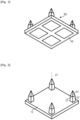
- a sensor comprises a support plate 10 provided with four microneedles 20, and preferably a plurality of support plates 10, in particular at least three support plates 10.
- the outline of the plate can be the subject of numerous variant embodiments. According to the representation given on the figures 1 to 5 , the plate 10 has a square outline.
- the four microneedles are located respectively near the corners of the plate 10.
- the microneedles 20 extend perpendicular to the base plane of the plate 10. In other words, the central axis 21 of each microneedle 20 extends perpendicular to the base surface of the plate 10.
- the face of the plate 10 opposite the microneedles 20 comprises four electrically conductive pads 30, each pad 30 being electrically connected to the active part 25 of each microneedle 20.
- the electrically conductive pads 30 allow electrical continuity of an electrode when they are electrically connected to a base, for example a working or counter-electrode, in the microneedle 20, and this potentially separately so that each working electrode is independent of the other working electrodes.
- these pads 30 may be made of a single material with the microneedles 20 or electrically connected to the microneedles 20 by any suitable means through or around the plate 10.
- the support plate 10 may be made of any electrically suitable material, for example electrically insulating or conductive.
- the microneedles 20 may be formed of any suitable material. They are suitable for conveying an electrical signal captured by the active surface 25.
- the microneedles 20 can be formed from polycarbonate or silicon.
- the microneedle(s) 20 are preferably solid, i.e. devoid of a cavity.
- the microneedle can mainly comprise silicon.
- the microneedle has an external non-conductive protective layer of SiO 2 , formed by oxidation of the silicon on the surface.
- the microneedle may not comprise an additional coating to the SiO 2 layer.
- each microneedle 20 comprises a base shaft 22 and a pointed apex 24.
- the shaft 22 may preferentially taper towards the pointed apex 24 of the microneedle 20.
- the pointed apex 24 has a slope greater than that of the shaft 22, that is to say it forms an angle B with the central axis 21 greater than the angle A formed between the base shaft 22 and the central axis 21.
- the microneedle 20 has a break or slope transition 23 between the base shaft 22 and the pointed summit. The slope transition 23 can be materialized by an edge.
- the pointed apex 24 extends exclusively at a distance of between 350 ⁇ m and 1100 ⁇ m from the base of the base barrel 22 of the microneedle, i.e. from the face 12 of the support plate 10, and preferably between 600 ⁇ m and 1000 ⁇ m from the base of the microneedle and this surface 12 of the support plate 10.
- the term “extends exclusively at a distance of between 350 ⁇ m and 1100 ⁇ m” means that the portion of the pointed apex 24 closest to the base of the base barrel is arranged at a distance greater than 350 ⁇ m from the base of the base barrel 22, and that the portion furthest from the base of the base barrel 22 is arranged at a distance less than 1100 ⁇ m.
- the surface area of the active detection part 25 must be between 0.04 and 0.9 mm 2 . Consequently, when the measurement is made with a single microneedle 20, the active part 25 of this microneedle 20 is between 0.04 and 0.9 mm 2 . When the measurement is made with several microneedles 20, the surface area of the aforementioned active part, between 0.04 and 0.9 mm 2 , is understood to be the total active surface area of the microneedles considered.
- the obelisk shape of the microneedles 20, or the shape of a similar circular body of revolution but having a break in slope between the base shaft 22 and the pointed apex 24, makes it possible to solve a problem posed by the microneedles 20 known from the state of the art, namely minimizing the penetration diameter into the skin while maximizing the surface area of the active part 25 present in the part of the skin between the epidermis and the nerves.
- microneedles 20 according to the present invention can be made using any suitable microfabrication method.
- the active part 25 comprises an electrically conductive face, preferably covered with a coating which is the subject of various variants depending on the type of measurement sought and the type of analyte to be measured.
- the active part 25 is provided with a coating capable of implementing an enzymatic reaction with the glucose.
- the active part 25 may also not comprise a coating specific to a predetermined analyte, for example in the case of the active part 25 of a counter-electrode or a reference electrode.
- a working electrode 70 comprises between one and seven, in particular between one and five and preferably between one and three active parts 25 each covering at least part of the surface of the pointed apex 24 of a different microneedle 20.
- the known systems of the state of the art do not allow the use of so few microneedles.
- the invention makes it possible to drastically reduce the number of microneedles 20 required for measurement compared to known systems of the state of the art, it is possible, for a given sensor surface, to minimize the density of microneedles.
- Each pair of adjacent microneedles 20 is preferably separated by a distance between the tips of the apexes 24 of at least 1 mm and preferably at least 1.5 mm, or even at least 1.8 mm where appropriate.
- This has the effect of avoiding a homogeneous deformation of the skin when a network of microneedles 20 comes into contact with the skin, known in other technical fields as the fakir effect, and on the contrary of promoting a deformation of the skin localized around each of the microneedles.
- the pain caused by the penetration of needles into the skin can be significantly reduced, or even eliminated and the penetration occurs very naturally, the needles having in fact become mechanically independent.
- the center distance l 3 between each pair of microneedles 20 is of the order of 1.5 mm.
- the sensor is preferably adapted to measure the presence or concentration of an analyte by electrochemistry.
- a sensor may comprise a working electrode 70, adapted to evaluate the presence of an analyte in the body of a user.
- the working electrode 70 comprises at least a first end electrically connected to a module configured to exploit the electrical signal of the working electrode 70, and at least one second end formed by the active portion 25. It may also comprise a plurality of second ends.
- the active portion 25 of the microneedle 20 covers at least a portion of the surface of the pointed apex 24 and preferably the entire surface of the pointed apex 24.
- the active portion 25, at the level of the pointed apex 24 is coated with any coating suitable for the desired measurement, typically a coating suitable for detecting blood glucose by electrochemistry.
- the sensor may comprise a counter electrode.
- the counter electrode may comprise a first end intended to be electrically connected to a module configured to exploit an electrical signal, and at least one other end for exploiting an electrical signal in the user's body.
- the other end of the counter electrode may cover a counter electrode microneedle, for example a microneedle according to the invention.
- the counter electrode does not have the same active surface area requirements as the working electrode.
- the pointed apex of the counter electrode may extend exclusively at a distance of between 100 ⁇ m and 1100 ⁇ m from the base shaft of the microneedle.
- the other end of the counter electrode may cover the entire surface of the counter electrode microneedle.
- each working electrode can be adapted to detect the same analyte as another working electrode, or be adapted to detect an analyte different from another working electrode.
- each working electrode may comprise an active part 25 comprising the same type of coating.
- each working electrode may also comprise different active parts 25, comprising different coatings, but adapted to detect the same analyte. The concentration of the analyte can thus be detected more precisely than by using a single coating for the active part 25.
- Each electrode can also be adapted to detect different analytes. Thus, it is possible to monitor several pathologies with the same monitoring system.
- the microneedle(s) 20 may be arranged on a support plate 10.
- the thickness e 1 of the support plate is advantageously between 0.1 mm and 1 mm, and preferably of the order of 0.2 mm.
- the dimensions of the microneedles 20 can be the subject of numerous variant embodiments. The same applies to the support plate 10.
- the support plate 10 has sides having a width l 1 less than 10 mm, advantageously less than 3 mm, for example of the order of 2.3 mm.
- the electrically conductive pads 30 are pads, for example square, having a side l 2 of the order of 0.8 mm. These pads 30 can be located at a distance e 2 of the order of 0.2 mm from the edges of the support plate.
- the support plate(s) 10 are adapted to be mounted on a support base 80.
- the support base 80 may be, for example, the housing 40, a capsule 50, or a structure for receiving the housing 40, for example linked to the body attachment means.
- Each support plate 10 may be fixedly mounted with eight or fewer microneedles 20, and preferably with four or fewer microneedles 20.
- the manufacturing frequency of a microneedle array 20 in which all the microneedles 20 are valid increases compared to microneedle arrays comprising, for example, more than 50 or more than 100 microneedles.
- the sensor may comprise a plurality of plates 10, each plate 10 having a limited number of microneedles, for example less than eight microneedles, and preferably less than four microneedles, so as to avoid rejection of a microneedle array due to the failure of one of the microneedles of the network. This helps reduce the manufacturing costs of the sensor.
- Each support plate 10 and the base 80 preferably comprise electrical tracks for connecting the microneedles 20.
- an electrode for example a working electrode or a counter electrode, can pass through the support plate 10, so as to have a first end in the support base and at least one other end on a microneedle 20.
- provision is made to use an electrically conductive adhesive so as to fixedly mount the support plate 10 on the support base 80 and to allow an electrical connection between the support base 80 and the support plate 10, and by extension the microneedle 20.
- the use of an adhesive to fixedly mount a support plate 10 on the support base 80 is particularly advantageous when a plurality of support plates 10 are mounted on the support bases 80, for example when more than three support plates 10, preferably more than four support plates 10, and in particular more than eight support plates 10, are mounted on the support base 80.
- the base 80 and the support plate(s) 10 preferably comprise complementary shaped elements intended to ensure the immobilization of the elementary support plates 10 on the support base 80.
- a shape-complementing element may preferably be a cavity formed in the support base 80, of geometry complementary to the contour of one or more support plates 10.
- the shape-complementing element may preferably be bosses arranged on the support base 80 and adapted to receive at least one support plate 10, for example so as to surround it and/or hold it.
- the support plate 10 and the microneedles may be held in a controlled position, until the support plate(s) 10 are fixed to the base 80.
- each of the support plates 10 may thus be mounted fixed in a perfectly controlled position.
- the support base 80 can be preferably adapted to receive the elementary support plates 10 at different depths.
- the support base 80 can be preferably adapted to receive the elementary support plates 10 at different depths.
- the support base 80 may comprise electrical tracks.
- the shape-complementing elements of the base 80 and the electrical tracks of the base 80 may be arranged so that a support plate 10 also has one or more electrical tracks facing the electrical track of the base 80.
- an electrode for example a working electrode or a counter-electrode, may be formed straddling the base and the support plate 10.
- One aspect of the invention is a method of manufacturing a body monitoring system according to the invention, in which the support plate(s) 10 on which the microneedles 20 are distributed are fixedly mounted on the support base 80, such that each of the microneedles 20 is electrically connected to the support base 80, separately or not.
- the support base 80 it is possible to control, from the support base 80, the potential of the electrode parts of the support plate 10 and of each microneedle 20.
- Each microneedle 20 may have an active part 25 comprising a coating comprising a biological active compound which may be denatured by excessively high temperatures.
- the step of fixed mounting of the support plate 10 is preferably carried out at a temperature below 80°C, in particular below 50°C. Thus, denaturation of the active compounds of the microneedles 20 is avoided.
- This fixed mounting step may be carried out by bonding by irradiation with ultraviolet rays between the support plate 10 and the support base 80, using an electrically conductive glue.
- the present invention can independently measure the blood glucose level using a plurality of working electrodes 70. This has a distinct advantage over the prior art where a such independent measurement using a working electrode comprising a single microneedle was not feasible because the measurement signal was too noisy using a single microneedle.
- the sensor preferably comprises several working electrodes 70, the measurement system being adapted to individually measure the electrical potential of each of the working electrodes 70.
- the measurement of the potential of each of the working electrodes 70 can be multiplexed.
- means are advantageously provided for rejecting the minimum or maximum measurement values of the potential associated with a set of measurements, which was impossible using the sensors of the prior art.
- the sensor according to the present invention can be implemented in different types of body monitoring system.
- the senor according to the invention is implemented in a monitoring system of the type illustrated in the figures 7 to 10 annexed.
- Such a system comprises a housing 40 in the form of a watch case comprising a bracelet 42 adapted to surround the wrist of an individual.
- the housing 40 houses a module configured to exploit the electrical signal delivered by each microneedle 20 and provide information representative of a physical quantity of the fluid, typically a blood sugar level.
- the body monitoring system preferably used according to the invention comprises a capsule 50 comprising at least one sensor of the aforementioned type, and preferably a plurality of sensors as will be described in more detail below.
- the body monitoring system further comprises a patch 60 to which the capsule 50 is attached, the patch 60 itself being provided with an adhesive allowing the patch and capsule 50 assembly to adhere to the skin of an individual.
- the capsule 50 preferably has the general shape of a ring comprising a plurality of hollow housings 52 adapted to each respectively receive the support plate 10 of a aforementioned sensor.
- the capsule 50 may comprise electrically conductive pads 54 intended to be placed opposite the electrically conductive pads 30 provided on the support plate 10, to ensure an electrical connection between the microneedles 20 and the module provided in the housing 40 to exploit the electrical signal thus collected.
- the pads 54 are themselves interconnected with the aforementioned module by electrically conductive tracks 56a.
- some of the ranges 54 can be individually connected to the aforementioned processing module by respective tracks 56a while other ranges 54 can be connected to the processing module by common tracks 56b.
- the present invention also relates to a method of body monitoring using a sensor comprising a microneedle of the aforementioned type.
- the monitoring method comprises a step of measuring bodily analyte using a microneedle 20 according to one embodiment of the invention.
- the sensor may comprise a plurality of working electrodes.
- the measurement may for example be implemented by polarizing the working electrode(s) and the counter electrode(s) at an electrical potential suitable for causing an oxidation-reduction reaction involving the analyte to be measured.
- the measuring step can preferably be implemented at least using two different working electrodes.
- the measuring step can for example be implemented independently, successively on each of the working electrodes 70, or in parallel on each of the working electrodes 70.
- the concentration of the electrolyte can be analyzed more precisely than with a system comprising for example a single working electrode having several ends in the form of microneedles.
- Another aspect of the invention is a method for measuring a body analyte comprising a step of penetrating the microneedles of a sensor according to the invention into the skin of a user.
- the needles of the sensor can be introduced into the skin without an applicator, due to the spacing of the microneedles 20.
- a low force compared to the force provided by an applicator can be used for the penetration of the microneedles.
- a force of less than 50 newtons, and preferably less than 30 newtons can be used for the penetration of the microneedles 20.
- the penetration of the microneedles can be implemented with the hand, or preferably with mechanical attachment means of the system, for example a bracelet.
Landscapes
- Health & Medical Sciences (AREA)
- Life Sciences & Earth Sciences (AREA)
- Physics & Mathematics (AREA)
- Surgery (AREA)
- General Health & Medical Sciences (AREA)
- Engineering & Computer Science (AREA)
- Biomedical Technology (AREA)
- Heart & Thoracic Surgery (AREA)
- Medical Informatics (AREA)
- Molecular Biology (AREA)
- Biophysics (AREA)
- Animal Behavior & Ethology (AREA)
- Pathology (AREA)
- Public Health (AREA)
- Veterinary Medicine (AREA)
- Optics & Photonics (AREA)
- Chemical & Material Sciences (AREA)
- Chemical Kinetics & Catalysis (AREA)
- General Chemical & Material Sciences (AREA)
- Emergency Medicine (AREA)
- Measurement Of The Respiration, Hearing Ability, Form, And Blood Characteristics Of Living Organisms (AREA)
Claims (13)
- Sensor für ein Körperüberwachungssystem mit Mikronadeln (20) zur Messung von Körperanalyten, umfassend eine Trägerbasis (80), mehrere elementare Trägerplatten (10) und mehrere Mikronadeln (20), die auf jeder elementaren Trägerplatte (10) verteilt sind, wobei jede elementare Trägerplatte (10) durch einen elektrisch leitenden Klebstoff fest auf der Trägerbasis (80) montiert ist, so dass eine elektrische Verbindung zwischen der Trägerbasis (80) und der Trägerplatte (10) ermöglicht wird.
- Sensor nach Anspruch 1, dadurch gekennzeichnet, dass die elementare Trägerplatte (10) mit zweihundert Mikronadeln (20) oder weniger, vorteilhafterweise mit acht Mikronadeln oder weniger und vorzugsweise mit vier Mikronadeln (20) oder weniger fest montiert ist.
- Sensor nach Anspruch 1 oder 2, dadurch gekennzeichnet, dass die elementare Trägerplatte (10) und die Trägerbasis (80) elektrische Bahnen zur Verbindung der Mikronadeln (20) aufweisen.
- Sensor nach einem der Ansprüche 1 bis 3, dadurch gekennzeichnet, dass die elementare Trägerplatte (10) kleiner als 10x10 mm und vorzugsweise kleiner als 3x3 mm ist.
- Sensor nach einem der Ansprüche 1 bis 4, dadurch gekennzeichnet, dass die Trägerbasis (80) und jede elementare Trägerplatte (10) Elemente mit komplementärer Form aufweisen, die dafür bestimmt sind, die Fixierung der elementaren Trägerplatten (10) auf der Trägerbasis zu gewährleisten.
- Sensor nach Anspruch 5, dadurch gekennzeichnet, dass die Elemente mit komplementärer Form in der Trägerbasis (80) ausgebildete Vertiefungen umfassen, deren Geometrie komplementär zu der Kontur der elementaren Trägerplatten (10) ist.
- Sensor nach Anspruch 5 oder 6, dadurch gekennzeichnet, dass die Elemente mit komplementärer Form auf der Trägerbasis (80) angeordnete Erhebungen umfassen, die für die Aufnahme mindestens einer Trägerplatte (10) ausgelegt sind.
- Sensor nach einem der Ansprüche 1 bis 7, dadurch gekennzeichnet, dass die Trägerbasis (80) für die Aufnahme der elementaren Trägerplatten (10) in unterschiedlichen Tiefen ausgelegt ist.
- Sensor nach einem der Ansprüche 1 bis 8, dadurch gekennzeichnet, dass jede Arbeitselektrode dafür ausgelegt ist, einen anderen Analyten als eine andere Arbeitselektrode zu erkennen.
- Sensor nach einem der Ansprüche 1 bis 9, dadurch gekennzeichnet, dass jede Arbeitselektrode dafür ausgelegt ist, den gleichen Analyten wie eine andere Arbeitselektrode zu erkennen.
- Körperüberwachungssystem, dadurch gekennzeichnet, dass es einen Sensor nach einem der Ansprüche 1 bis 10 umfasst und dass es ferner ein Modul umfasst, das so konfiguriert ist, dass es ein von der Trägerbasis (80) geliefertes elektrisches Signal auswertet und eine für einen Analyten repräsentative Information liefert.
- Verfahren zur Herstellung eines Sensors nach einem der Ansprüche 1 bis 10, umfassend mindestens einen Schritt der festen Montage einer Trägerplatte (10), auf der mehrere Mikronadeln (20) verteilt sind, auf einer Trägerbasis (80), so dass jede der Mikronadeln (20) elektrisch mit der Trägerbasis (80) verbunden ist.
- Herstellungsverfahren nach Anspruch 12, wobei die feste Montage der Trägerplatte (10) auf der Trägerbasis (80) bei einer Temperatur unter 50°C durchgeführt wird.
Applications Claiming Priority (2)
| Application Number | Priority Date | Filing Date | Title |
|---|---|---|---|
| EP19290068.6A EP3772332A1 (de) | 2019-08-08 | 2019-08-08 | Körperüberwachungssystem mit einer mikronadel |
| PCT/EP2020/072310 WO2021023882A1 (fr) | 2019-08-08 | 2020-08-07 | Systeme de surveillance corporelle comprenant une microaiguille |
Publications (2)
| Publication Number | Publication Date |
|---|---|
| EP4009864A1 EP4009864A1 (de) | 2022-06-15 |
| EP4009864B1 true EP4009864B1 (de) | 2025-03-19 |
Family
ID=67981993
Family Applications (2)
| Application Number | Title | Priority Date | Filing Date |
|---|---|---|---|
| EP19290068.6A Withdrawn EP3772332A1 (de) | 2019-08-08 | 2019-08-08 | Körperüberwachungssystem mit einer mikronadel |
| EP20753756.4A Active EP4009864B1 (de) | 2019-08-08 | 2020-08-07 | Körperüberwachungssystem mit einer mikronadel |
Family Applications Before (1)
| Application Number | Title | Priority Date | Filing Date |
|---|---|---|---|
| EP19290068.6A Withdrawn EP3772332A1 (de) | 2019-08-08 | 2019-08-08 | Körperüberwachungssystem mit einer mikronadel |
Country Status (4)
| Country | Link |
|---|---|
| US (1) | US12533082B2 (de) |
| EP (2) | EP3772332A1 (de) |
| CN (1) | CN114144114A (de) |
| WO (1) | WO2021023882A1 (de) |
Families Citing this family (2)
| Publication number | Priority date | Publication date | Assignee | Title |
|---|---|---|---|---|
| US12318224B2 (en) | 2023-02-23 | 2025-06-03 | Aquilx Incorporated | Wearable biosensor device |
| US20260026744A1 (en) * | 2024-07-25 | 2026-01-29 | Panther Life Sciences Corporation | Microneedle array systems and devices, and methods associated with manufacturing and use |
Family Cites Families (11)
| Publication number | Priority date | Publication date | Assignee | Title |
|---|---|---|---|---|
| US6767341B2 (en) * | 2001-06-13 | 2004-07-27 | Abbott Laboratories | Microneedles for minimally invasive drug delivery |
| EP1987761B1 (de) * | 2007-05-03 | 2019-10-23 | F. Hoffmann-La Roche AG | Schlauchförmiger Sensor zum Nachweis eines Analyten |
| US8874182B2 (en) | 2013-01-15 | 2014-10-28 | Google Inc. | Encapsulated electronics |
| US10820860B2 (en) * | 2013-03-14 | 2020-11-03 | One Drop Biosensor Technologies, Llc | On-body microsensor for biomonitoring |
| US20150335288A1 (en) | 2013-06-06 | 2015-11-26 | Tricord Holdings, Llc | Modular physiologic monitoring systems, kits, and methods |
| US20150276758A1 (en) * | 2014-04-01 | 2015-10-01 | Anteneh Addisu | Biomarker Detection Device for Monitoring Peptide and Non-Peptide Markers |
| WO2016153313A1 (en) * | 2015-03-25 | 2016-09-29 | Samsung Electronics Co., Ltd. | Wearable electronic device |
| FR3059886B1 (fr) * | 2016-12-09 | 2021-04-09 | Pk Paris | Dispositif de surveillance corporelle |
| US11278217B2 (en) * | 2017-03-31 | 2022-03-22 | RichHealth Technology Corporation | Transdermal microneedle array patch |
| US11045142B1 (en) * | 2017-04-29 | 2021-06-29 | Biolinq, Inc. | Heterogeneous integration of silicon-fabricated solid microneedle sensors and CMOS circuitry |
| FR3076706B1 (fr) * | 2018-01-16 | 2026-02-20 | Pk Paris | Systeme de surveillance corporelle par electrophorese |
-
2019
- 2019-08-08 EP EP19290068.6A patent/EP3772332A1/de not_active Withdrawn
-
2020
- 2020-08-07 EP EP20753756.4A patent/EP4009864B1/de active Active
- 2020-08-07 US US17/633,418 patent/US12533082B2/en active Active
- 2020-08-07 CN CN202080053030.2A patent/CN114144114A/zh not_active Withdrawn
- 2020-08-07 WO PCT/EP2020/072310 patent/WO2021023882A1/fr not_active Ceased
Also Published As
| Publication number | Publication date |
|---|---|
| WO2021023882A1 (fr) | 2021-02-11 |
| CN114144114A (zh) | 2022-03-04 |
| US12533082B2 (en) | 2026-01-27 |
| US20220287638A1 (en) | 2022-09-15 |
| EP3772332A1 (de) | 2021-02-10 |
| EP4009864A1 (de) | 2022-06-15 |
Similar Documents
| Publication | Publication Date | Title |
|---|---|---|
| EP4009865B1 (de) | Körperüberwachungssystem mit einer mikronadel | |
| US11865289B2 (en) | On-body microsensor for biomonitoring | |
| EP3829437B1 (de) | Mikronadeleindringungsmanagement | |
| FR3099696A1 (fr) | Systeme de surveillance corporelle comprenant une microaiguille | |
| WO2022136785A1 (fr) | Dispositif de surveillance corporelle a gamme de detection etendue | |
| EP4009864B1 (de) | Körperüberwachungssystem mit einer mikronadel | |
| EP3829418B1 (de) | Metall-oberflächen-verhältnis einer mikrokanüle | |
| WO2021023887A1 (fr) | Systeme de surveillance corporelle comprenant une microaiguille | |
| EP4404825B1 (de) | Anordnung zur vorbereitung eines sensors für eine körperüberwachungsvorrichtung | |
| EP3772330A1 (de) | Körperüberwachungssystem mit einer mikronadel | |
| EP4186421B1 (de) | Verfahren zur herstellung eines elementaren moduls eines mikronadelsensors | |
| EP4395642B1 (de) | Körperüberwachungsvorrichtung mit verbesserten kontakten | |
| EP1363699B1 (de) | Implantierbare elektrodenstruktur | |
| FR3138320A1 (fr) | Procédé de fabrication d’une micro-aiguille et en particulier métallisation de la pointe d’une microaiguille | |
| FR3138774A1 (fr) | Procédé de fabrication d’une micro-aiguille en particulier métallisation de la pointe d’une microaiguille. | |
| EP4319635A1 (de) | Körperüberwachungsvorrichtung mit verbesserten elektrischen kontakten | |
| FR3110382A1 (fr) | Capteur pour système de surveillance corporelle monté en surface | |
| FR3132835A1 (fr) | Capteur à microaiguilles comprenant une base, au moins un module élémentaire de support de microaiguille | |
| WO2022195236A1 (fr) | Capteur pour dispositif de surveillance corporelle limitant les irritations |
Legal Events
| Date | Code | Title | Description |
|---|---|---|---|
| STAA | Information on the status of an ep patent application or granted ep patent |
Free format text: STATUS: UNKNOWN |
|
| STAA | Information on the status of an ep patent application or granted ep patent |
Free format text: STATUS: THE INTERNATIONAL PUBLICATION HAS BEEN MADE |
|
| PUAI | Public reference made under article 153(3) epc to a published international application that has entered the european phase |
Free format text: ORIGINAL CODE: 0009012 |
|
| STAA | Information on the status of an ep patent application or granted ep patent |
Free format text: STATUS: REQUEST FOR EXAMINATION WAS MADE |
|
| 17P | Request for examination filed |
Effective date: 20220214 |
|
| AK | Designated contracting states |
Kind code of ref document: A1 Designated state(s): AL AT BE BG CH CY CZ DE DK EE ES FI FR GB GR HR HU IE IS IT LI LT LU LV MC MK MT NL NO PL PT RO RS SE SI SK SM TR |
|
| DAV | Request for validation of the european patent (deleted) | ||
| DAX | Request for extension of the european patent (deleted) | ||
| GRAP | Despatch of communication of intention to grant a patent |
Free format text: ORIGINAL CODE: EPIDOSNIGR1 |
|
| STAA | Information on the status of an ep patent application or granted ep patent |
Free format text: STATUS: GRANT OF PATENT IS INTENDED |
|
| INTG | Intention to grant announced |
Effective date: 20230329 |
|
| 19U | Interruption of proceedings before grant |
Effective date: 20230427 |
|
| 19W | Proceedings resumed before grant after interruption of proceedings |
Effective date: 20240603 |
|
| RAP3 | Party data changed (applicant data changed or rights of an application transferred) |
Owner name: WIZP AS |
|
| GRAJ | Information related to disapproval of communication of intention to grant by the applicant or resumption of examination proceedings by the epo deleted |
Free format text: ORIGINAL CODE: EPIDOSDIGR1 |
|
| STAA | Information on the status of an ep patent application or granted ep patent |
Free format text: STATUS: REQUEST FOR EXAMINATION WAS MADE |
|
| GRAP | Despatch of communication of intention to grant a patent |
Free format text: ORIGINAL CODE: EPIDOSNIGR1 |
|
| INTC | Intention to grant announced (deleted) | ||
| STAA | Information on the status of an ep patent application or granted ep patent |
Free format text: STATUS: GRANT OF PATENT IS INTENDED |
|
| INTG | Intention to grant announced |
Effective date: 20241107 |
|
| GRAS | Grant fee paid |
Free format text: ORIGINAL CODE: EPIDOSNIGR3 |
|
| GRAA | (expected) grant |
Free format text: ORIGINAL CODE: 0009210 |
|
| STAA | Information on the status of an ep patent application or granted ep patent |
Free format text: STATUS: THE PATENT HAS BEEN GRANTED |
|
| AK | Designated contracting states |
Kind code of ref document: B1 Designated state(s): AL AT BE BG CH CY CZ DE DK EE ES FI FR GB GR HR HU IE IS IT LI LT LU LV MC MK MT NL NO PL PT RO RS SE SI SK SM TR |
|
| REG | Reference to a national code |
Ref country code: GB Ref legal event code: FG4D Free format text: NOT ENGLISH |
|
| REG | Reference to a national code |
Ref country code: CH Ref legal event code: EP |
|
| REG | Reference to a national code |
Ref country code: DE Ref legal event code: R096 Ref document number: 602020047947 Country of ref document: DE |
|
| REG | Reference to a national code |
Ref country code: IE Ref legal event code: FG4D Free format text: LANGUAGE OF EP DOCUMENT: FRENCH |
|
| PG25 | Lapsed in a contracting state [announced via postgrant information from national office to epo] |
Ref country code: RS Free format text: LAPSE BECAUSE OF FAILURE TO SUBMIT A TRANSLATION OF THE DESCRIPTION OR TO PAY THE FEE WITHIN THE PRESCRIBED TIME-LIMIT Effective date: 20250619 |
|
| PG25 | Lapsed in a contracting state [announced via postgrant information from national office to epo] |
Ref country code: FI Free format text: LAPSE BECAUSE OF FAILURE TO SUBMIT A TRANSLATION OF THE DESCRIPTION OR TO PAY THE FEE WITHIN THE PRESCRIBED TIME-LIMIT Effective date: 20250319 |
|
| REG | Reference to a national code |
Ref country code: LT Ref legal event code: MG9D |
|
| PG25 | Lapsed in a contracting state [announced via postgrant information from national office to epo] |
Ref country code: NO Free format text: LAPSE BECAUSE OF FAILURE TO SUBMIT A TRANSLATION OF THE DESCRIPTION OR TO PAY THE FEE WITHIN THE PRESCRIBED TIME-LIMIT Effective date: 20250619 |
|
| PG25 | Lapsed in a contracting state [announced via postgrant information from national office to epo] |
Ref country code: HR Free format text: LAPSE BECAUSE OF FAILURE TO SUBMIT A TRANSLATION OF THE DESCRIPTION OR TO PAY THE FEE WITHIN THE PRESCRIBED TIME-LIMIT Effective date: 20250319 |
|
| PG25 | Lapsed in a contracting state [announced via postgrant information from national office to epo] |
Ref country code: LV Free format text: LAPSE BECAUSE OF FAILURE TO SUBMIT A TRANSLATION OF THE DESCRIPTION OR TO PAY THE FEE WITHIN THE PRESCRIBED TIME-LIMIT Effective date: 20250319 |
|
| PG25 | Lapsed in a contracting state [announced via postgrant information from national office to epo] |
Ref country code: GR Free format text: LAPSE BECAUSE OF FAILURE TO SUBMIT A TRANSLATION OF THE DESCRIPTION OR TO PAY THE FEE WITHIN THE PRESCRIBED TIME-LIMIT Effective date: 20250620 Ref country code: BG Free format text: LAPSE BECAUSE OF FAILURE TO SUBMIT A TRANSLATION OF THE DESCRIPTION OR TO PAY THE FEE WITHIN THE PRESCRIBED TIME-LIMIT Effective date: 20250319 |
|
| REG | Reference to a national code |
Ref country code: NL Ref legal event code: MP Effective date: 20250319 |
|
| REG | Reference to a national code |
Ref country code: AT Ref legal event code: MK05 Ref document number: 1776259 Country of ref document: AT Kind code of ref document: T Effective date: 20250319 |
|
| PG25 | Lapsed in a contracting state [announced via postgrant information from national office to epo] |
Ref country code: NL Free format text: LAPSE BECAUSE OF FAILURE TO SUBMIT A TRANSLATION OF THE DESCRIPTION OR TO PAY THE FEE WITHIN THE PRESCRIBED TIME-LIMIT Effective date: 20250319 |
|
| PG25 | Lapsed in a contracting state [announced via postgrant information from national office to epo] |
Ref country code: SE Free format text: LAPSE BECAUSE OF FAILURE TO SUBMIT A TRANSLATION OF THE DESCRIPTION OR TO PAY THE FEE WITHIN THE PRESCRIBED TIME-LIMIT Effective date: 20250319 |
|
| PG25 | Lapsed in a contracting state [announced via postgrant information from national office to epo] |
Ref country code: SM Free format text: LAPSE BECAUSE OF FAILURE TO SUBMIT A TRANSLATION OF THE DESCRIPTION OR TO PAY THE FEE WITHIN THE PRESCRIBED TIME-LIMIT Effective date: 20250319 |
|
| PG25 | Lapsed in a contracting state [announced via postgrant information from national office to epo] |
Ref country code: ES Free format text: LAPSE BECAUSE OF FAILURE TO SUBMIT A TRANSLATION OF THE DESCRIPTION OR TO PAY THE FEE WITHIN THE PRESCRIBED TIME-LIMIT Effective date: 20250319 Ref country code: PT Free format text: LAPSE BECAUSE OF FAILURE TO SUBMIT A TRANSLATION OF THE DESCRIPTION OR TO PAY THE FEE WITHIN THE PRESCRIBED TIME-LIMIT Effective date: 20250721 |
|
| PGFP | Annual fee paid to national office [announced via postgrant information from national office to epo] |
Ref country code: DE Payment date: 20250812 Year of fee payment: 6 |
|
| PG25 | Lapsed in a contracting state [announced via postgrant information from national office to epo] |
Ref country code: IT Free format text: LAPSE BECAUSE OF FAILURE TO SUBMIT A TRANSLATION OF THE DESCRIPTION OR TO PAY THE FEE WITHIN THE PRESCRIBED TIME-LIMIT Effective date: 20250319 Ref country code: PL Free format text: LAPSE BECAUSE OF FAILURE TO SUBMIT A TRANSLATION OF THE DESCRIPTION OR TO PAY THE FEE WITHIN THE PRESCRIBED TIME-LIMIT Effective date: 20250319 |
|
| PGFP | Annual fee paid to national office [announced via postgrant information from national office to epo] |
Ref country code: GB Payment date: 20250826 Year of fee payment: 6 |
|
| PG25 | Lapsed in a contracting state [announced via postgrant information from national office to epo] |
Ref country code: AT Free format text: LAPSE BECAUSE OF FAILURE TO SUBMIT A TRANSLATION OF THE DESCRIPTION OR TO PAY THE FEE WITHIN THE PRESCRIBED TIME-LIMIT Effective date: 20250319 |
|
| PGFP | Annual fee paid to national office [announced via postgrant information from national office to epo] |
Ref country code: FR Payment date: 20250710 Year of fee payment: 6 |
|
| PGFP | Annual fee paid to national office [announced via postgrant information from national office to epo] |
Ref country code: CH Payment date: 20250901 Year of fee payment: 6 |
|
| PG25 | Lapsed in a contracting state [announced via postgrant information from national office to epo] |
Ref country code: EE Free format text: LAPSE BECAUSE OF FAILURE TO SUBMIT A TRANSLATION OF THE DESCRIPTION OR TO PAY THE FEE WITHIN THE PRESCRIBED TIME-LIMIT Effective date: 20250319 Ref country code: CZ Free format text: LAPSE BECAUSE OF FAILURE TO SUBMIT A TRANSLATION OF THE DESCRIPTION OR TO PAY THE FEE WITHIN THE PRESCRIBED TIME-LIMIT Effective date: 20250319 |
|
| PG25 | Lapsed in a contracting state [announced via postgrant information from national office to epo] |
Ref country code: RO Free format text: LAPSE BECAUSE OF FAILURE TO SUBMIT A TRANSLATION OF THE DESCRIPTION OR TO PAY THE FEE WITHIN THE PRESCRIBED TIME-LIMIT Effective date: 20250319 |
|
| PG25 | Lapsed in a contracting state [announced via postgrant information from national office to epo] |
Ref country code: SK Free format text: LAPSE BECAUSE OF FAILURE TO SUBMIT A TRANSLATION OF THE DESCRIPTION OR TO PAY THE FEE WITHIN THE PRESCRIBED TIME-LIMIT Effective date: 20250319 |
|
| PG25 | Lapsed in a contracting state [announced via postgrant information from national office to epo] |
Ref country code: IS Free format text: LAPSE BECAUSE OF FAILURE TO SUBMIT A TRANSLATION OF THE DESCRIPTION OR TO PAY THE FEE WITHIN THE PRESCRIBED TIME-LIMIT Effective date: 20250719 |
|
| RAP4 | Party data changed (patent owner data changed or rights of a patent transferred) |
Owner name: WIZP AS |
|
| REG | Reference to a national code |
Ref country code: DE Ref legal event code: R097 Ref document number: 602020047947 Country of ref document: DE |
|
| PG25 | Lapsed in a contracting state [announced via postgrant information from national office to epo] |
Ref country code: DK Free format text: LAPSE BECAUSE OF FAILURE TO SUBMIT A TRANSLATION OF THE DESCRIPTION OR TO PAY THE FEE WITHIN THE PRESCRIBED TIME-LIMIT Effective date: 20250319 |
|
| PLBE | No opposition filed within time limit |
Free format text: ORIGINAL CODE: 0009261 |
|
| STAA | Information on the status of an ep patent application or granted ep patent |
Free format text: STATUS: NO OPPOSITION FILED WITHIN TIME LIMIT |
|
| REG | Reference to a national code |
Ref country code: CH Ref legal event code: L10 Free format text: ST27 STATUS EVENT CODE: U-0-0-L10-L00 (AS PROVIDED BY THE NATIONAL OFFICE) Effective date: 20260128 |
|
| 26N | No opposition filed |
Effective date: 20251222 |
|
| PG25 | Lapsed in a contracting state [announced via postgrant information from national office to epo] |
Ref country code: MC Free format text: LAPSE BECAUSE OF FAILURE TO SUBMIT A TRANSLATION OF THE DESCRIPTION OR TO PAY THE FEE WITHIN THE PRESCRIBED TIME-LIMIT Effective date: 20250319 |
|
| PG25 | Lapsed in a contracting state [announced via postgrant information from national office to epo] |
Ref country code: LU Free format text: LAPSE BECAUSE OF NON-PAYMENT OF DUE FEES Effective date: 20250807 |
|
| REG | Reference to a national code |
Ref country code: CH Ref legal event code: R17 Free format text: ST27 STATUS EVENT CODE: U-0-0-R10-R17 (AS PROVIDED BY THE NATIONAL OFFICE) Effective date: 20260417 |