EP4009873B1 - Prothèse dentaire retenue par frottement de maintien - Google Patents
Prothèse dentaire retenue par frottement de maintien Download PDFInfo
- Publication number
- EP4009873B1 EP4009873B1 EP20850778.0A EP20850778A EP4009873B1 EP 4009873 B1 EP4009873 B1 EP 4009873B1 EP 20850778 A EP20850778 A EP 20850778A EP 4009873 B1 EP4009873 B1 EP 4009873B1
- Authority
- EP
- European Patent Office
- Prior art keywords
- denture
- prong
- retention system
- anchor
- connector
- Prior art date
- Legal status (The legal status is an assumption and is not a legal conclusion. Google has not performed a legal analysis and makes no representation as to the accuracy of the status listed.)
- Active
Links
Images

Classifications
-
- A—HUMAN NECESSITIES
- A61—MEDICAL OR VETERINARY SCIENCE; HYGIENE
- A61C—DENTISTRY; APPARATUS OR METHODS FOR ORAL OR DENTAL HYGIENE
- A61C8/00—Means to be fixed to the jaw-bone for consolidating natural teeth or for fixing dental prostheses thereon; Dental implants; Implanting tools
- A61C8/0093—Features of implants not otherwise provided for
- A61C8/0095—Total denture implant
-
- A—HUMAN NECESSITIES
- A61—MEDICAL OR VETERINARY SCIENCE; HYGIENE
- A61C—DENTISTRY; APPARATUS OR METHODS FOR ORAL OR DENTAL HYGIENE
- A61C8/00—Means to be fixed to the jaw-bone for consolidating natural teeth or for fixing dental prostheses thereon; Dental implants; Implanting tools
- A61C8/0048—Connecting the upper structure to the implant, e.g. bridging bars
- A61C8/005—Connecting devices for joining an upper structure with an implant member, e.g. spacers
- A61C8/0065—Connecting devices for joining an upper structure with an implant member, e.g. spacers with expandable or compressible means
-
- A—HUMAN NECESSITIES
- A61—MEDICAL OR VETERINARY SCIENCE; HYGIENE
- A61C—DENTISTRY; APPARATUS OR METHODS FOR ORAL OR DENTAL HYGIENE
- A61C8/00—Means to be fixed to the jaw-bone for consolidating natural teeth or for fixing dental prostheses thereon; Dental implants; Implanting tools
- A61C8/0086—Means to be fixed to the jaw-bone for consolidating natural teeth or for fixing dental prostheses thereon; Dental implants; Implanting tools with shock absorbing means
-
- A—HUMAN NECESSITIES
- A61—MEDICAL OR VETERINARY SCIENCE; HYGIENE
- A61C—DENTISTRY; APPARATUS OR METHODS FOR ORAL OR DENTAL HYGIENE
- A61C13/00—Dental prostheses; Making same
- A61C13/225—Fastening prostheses in the mouth
- A61C13/273—Fastening prostheses in the mouth removably secured to residual teeth by using bolts or locks
Definitions
- the present invention relates to dentistry, and more particularly, to functionally secure frictionally retained dentures.
- Dentures are typically utilized within the dental field to replace a plurality of natural teeth using a single assembly. Dentures are typically secured to a patient's jaw by use of previously installed dental implants. A number of difficulties arise with prior art dentures. One is that they may require a relatively great number of implants to be properly supported within the mouth. Another is that it may be objectionable to fasten dentures in place using screws or bolts secured to the denture and threaded directly into the implant. For one thing, the implant may be oriented at an angle unsuitable for passing into or through the denture. Another issue may be that bone tissue at any given desired implant site may be eroded or otherwise unsuitable for securely supporting an implant.
- US 4 884 970 A discloses a retention system for frictionally retaining a denture to a jaw of a patient, the retention system comprising: at least one prong anchor having a prong reception sites and an implant connector configured to secure the prong anchor to a dental implant; a denture comprising a base, at least one prosthetic tooth mounted to the base, at least one opening in the base, the opening dimensioned and configured to receive an exposed portion of the prong anchor therein, and a prong passages in the base, each of the prong passages dimensioned and configured to slidably receive a prong therethrough; and a denture connector having a prong dimensioned and configured to pass through the prong passages of the denture and to be received within the prong reception sites of the prong anchor, wherein the prong reception sites of the prong anchor and the prong passages of the base of the denture are oriented to enable the parallel prongs of the denture connector to pass through the denture and be received laterally within the at least one prong
- US 5 503 557 A discloses a retention system for frictionally retaining a denture to a jaw of a patient, the retention system comprising: at least one prong anchor having a prong reception sites and an implant connector configured to secure the prong anchor to a dental implant; a denture comprising a base, at least one prosthetic tooth mounted to the base, at least one opening in the base, the opening dimensioned and configured to receive an exposed portion of the prong anchor therein, and a prong passages in the base, each of the prong passages dimensioned and configured to slidably receive a prong therethrough; and a denture connector having a prong dimensioned and configured to pass through the prong passages of the denture and to be received within the prong reception sites of the prong anchor, wherein the prong reception sites of the prong anchor and the prong passages of the base of the denture are oriented to enable the parallel prongs of the denture connector to pass through the denture and be received laterally within the at least one prong
- the present invention sets forth a construction for manually, expeditiously, and securely mounting a denture on the jaw of a patient, using implants.
- An anchor for receiving prongs is threaded to each of one or more implants in the mouth.
- a denture having prong passages is placed onto jaw bone or overlying tissue, above the implant (if the lower jaw is being treated).
- the anchor penetrates the denture, occupying an opening in the denture.
- a pronged denture connector is installed such that the prongs pass through the prong passages of the denture and penetrate the prong reception sites of the anchor.
- the prongs are frictionally secured in place by an elastic member lining the prong passages of the denture and constricting over inserted prongs.
- the denture may comprise synthetic resin reinforced by a metallic reinforcing bar.
- the denture may include a recess configured to enable a pry tool to bear against the denture connector to remove the latter, for example, when replacing or servicing the denture.
- the novel arrangement may be utilized with both partial and full arch dentures, the dentures stably secured using only two implants. Also, as will be further detailed hereinafter, it is not necessary to establish great precision in having the prongs and prong reception sites sized and aligned.
- the present invention provides improved elements and arrangements thereof by apparatus for the purposes described which is inexpensive, dependable, and fully effective in accomplishing its intended purposes.
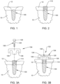
- FIG. 1 there is shown an implant 100 installed in a jaw bone 10 of a patient, with soft tissue such as gum tissue 12 overlying jaw bone 10.
- Implant 100 may be conventional and may preexist installation of a denture 102 (see Figs. 6-9 ), or alternatively, may be fabricated and installed specifically for installation of denture 102.
- a seat 110 for seating elements of a novel retention system for denture 102 sits atop implant 100.
- Seat 110 elevates a load bearing working surface of implant 100 from a location recessed within the jaw to a location reasonably flush with gum tissue 12. It would be possible to omit seat 110 if implant 100 were flush with the upper surface of jaw tissue. Ordinarily, implant 100 sits recessed below such upper surface.
- orientational terms such as overlying, atop, laterally, vertically, and transverse refer to the subject drawing as viewed by an observer.
- the drawing figures depict their subject matter in orientations of normal use, which could obviously change with changes in posture and position of the novel denture retention system as installed in a patient, or with use of an opposed jaw (drawings illustrate a lower jaw). Therefore, orientational terms must be understood to provide semantic basis for purposes of description, and do not limit the invention or its component parts in any particular way.
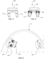
- the retention system may comprise at least one prong anchor 104 (shown isolated from other elements in Fig. 3A ) having a plurality of prong reception sites 106 and an implant connector (e.g., a screw 108) configured to secure prong anchor 104 to dental implant 100.
- an implant connector e.g., a screw 108
- the retention system may also comprise denture 102 comprising a base 112 ( Figs. 8 and 9 ), at least one prosthetic tooth 114 ( Fig. 8 ) mounted to base 112, at least one opening 116 ( Fig. 7 ) in base 112, opening 116 dimensioned and configured to receive an exposed portion of prong anchor 104 therein, and a plurality of prong passages in base 112.
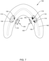
- Each of the prong passages is dimensioned and configured to slidably receive a prong 118 ( Fig. 4 ) therethrough.
- the retention system also includes a denture connector 120 ( Figs. 4-6 ) having a plurality of parallel prongs 118 dimensioned and configured to pass through the prong passages of denture 102 and to be received within prong reception sites 106 ( Figs. 3A, 3B ) of prong anchor 104.
- a denture connector 120 Figs. 4-6
- the retention system also includes a denture connector 120 ( Figs. 4-6 ) having a plurality of parallel prongs 118 dimensioned and configured to pass through the prong passages of denture 102 and to be received within prong reception sites 106 ( Figs. 3A, 3B ) of prong anchor 104.
- Prong reception sites 106 of prong anchor 104 and the prong passages of base 112 of denture 102 are oriented to enable parallel prongs 118 of denture connector 120 to pass through denture 102 and be received laterally within the at least one prong anchor 104 when prong anchor 104 is coupled to dental implant 100 and dental implant 100 is vertically oriented.
- prongs 118 With potential play of prongs 118 with respect to prong passages in denture 102, provision of two prongs 118 stabilizes coupling of denture 102 to prong anchor 104 and hence to the jaw.
- Base 112 of denture 102 both establishes a structural member for engaging prong anchor 104 and denture connector 120, and also is preferably configured to provide realistic visual transition from the jaw to gum tissue surrounding prosthetic teeth 114.
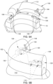
- Fig. 9A shows denture 102 about to be lowered onto gum tissue, so that prongs 118 of denture connector 120 will enter prong reception sites 106. It will be appreciated that prong reception sites guide prongs 118 into place, but need not receive prongs 118 with great precision or with very close fit. Desired precision is provided by barrels 130, to be described hereinafter.
- Fig. 9B a frontal view, shows denture 102 fully seated onto physiological features of the jaw of the patient, with denture connector 120 fully inserted.
- denture 102 is held in place by interference fit of prongs 118 with prong reception sites 106, in that denture 102 cannot be elevated from its seated or installed position (as shown e.g. in Fig. 9B ).
- the retention system may further comprise a metallic reinforcement bar 142 in base 112 of the denture, to distribute loads imposed for example by chewing when denture 102 is installed in the patient.
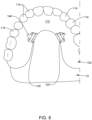
- Fig. 7 depicts denture 102 in an exemplary final form; that is, with barrels 130 fixed thereto, for example, by resinous cement, and with prongs 118 of denture connector entrapped by barrels 130, as will be described hereinafter.
- Prong anchor 104 may include two prong reception sites 106, with one prong reception site 106 on each side of the implant connector (e.g., screw 108). This arrangement symmetrically and stably distributes forces from clamping denture 102 to prong anchor 104 by using dual prong denture connector 120.
- implant connector e.g., screw 108
- Prong anchor 104 may comprise a bore 122 ( Fig. 3B ) in prong anchor 104 and a shoulder 124 in bore 122.
- Shoulder 124 is dimensioned and configured to entrap a head 126 ( Fig 3A ) of a threaded fastener (e.g., screw 108) when a shaft 128 ( Fig 3A ) of the threaded fastener is passed through bore 122.
- a threaded fastener e.g., screw 108
- Prong anchor 104 may further comprise the threaded fastener (i.e., screw 108) having threaded shaft 128 matingly compatible with female threads (not shown, but conventional in dental implants) of dental implant 100 and head 126 greater in a transverse dimension than threaded shaft 128.
- screw 108 the threaded fastener
- threaded shaft 128 matingly compatible with female threads (not shown, but conventional in dental implants) of dental implant 100 and head 126 greater in a transverse dimension than threaded shaft 128.
- denture 102 may be a full arch denture 102 spanning at least two dental implants 100 (as seen in Figs. 6 and 9 ). However, as seen in Fig. 10 , denture 102 may be fabricated as a partial arch denture 102 spanning at least two dental implants 100. Therefore, the novel retention system can be used when replacing all teeth of a dental arch, and also when replacing only some of the teeth of a dental arch.
- each prong passage (passages are not separately shown, but will be understood to be passages capable of slidably receiving barrels 130) of denture 120 may include a radially elastic member releasably engaging a respective prong 118 of denture connector 120 when denture connector 120 is fully installed through denture 102.
- Each radially elastic member may comprise a metallic barrel (or sleeve) 130 slotted to accommodate radial expansion.
- the radially elastic member in a form other than that of metallic barrel 130.
- the radially elastic member guides its associated prong 118 during insertion of the latter, while providing some play to overcome the need for extreme precision.
- Metallic barrel 130 enables a washer based retention feature preventing unintended disengagement of denture connector 120.
- Each one of prongs 118 may have a circumferential groove 132 for receiving an internal surface of an expansible washer 134 to retain a respective prong 118 within metallic barrel 130.
- Each one of metallic barrels 130 has an internal groove 136 ( Fig. 12 ) for receiving an outer surface of expansible washer 134.
- Circumferential groove 132 may have one tapered end wall 138 ( Fig. 13 ) to facilitate expansion of washer 134 when denture connector 120 is inserted into the retention system, and an opposed square cut end wall 140 to oppose excessive withdrawal of denture connector 120.
- washer 134 sits in circumferential groove 132 and is expanded first when encountering a blunt end of a prong 118 and remains expanded as it rides along the surface of the prong 118 as the denture is fully secured in place.
- prong 118 is moved in the opposite direction until washer 134 contracts and again sits in circumferential groove 132 of prong 118. At this position, further movement of prong 118 in this opposite direction is prevented as it results in the washer 134 encountering non-tapered square cut end wall 140 of the prong 118. This encounter will not expand washer 134, and excessive withdrawal of prongs 118 is prevented.
- circumferential grooves 132 The purpose of circumferential grooves 132 is to retain denture connector 120 on denture 102.
- washer 134 is expanded by contact with the blunt end of each prong 118, constricts as it passes over circumferential groove 132.
- tapered end wall 138 facilitates expansion of washer 134, the latter spreading or opening to accommodate passage of prong 118 to the fully installed position.
- the radial elastic member (e.g., barrels 130) frictionally retains prongs 118 in place. Prongs 118 interengage prong reception sites 106 to retain denture 102 against the jaw by interference fit.
- Denture 102 may further comprise a recess 144 configured to provide access for a pry tool (not shown) to dislodge denture connector 120 from an installed position in the retention system.
- Implant 100, prong anchor 104, seat 110, denture connector 120, and reinforcement bar 142 may be fabricated from a biocompatible metal such as titanium or titanium alloy. It is contemplated that prong anchor 104, denture connector 120, and reinforcement bar 142 will be fabricated with dimensions and configuration unique to each patient. Denture 102 may utilize conventional dental resins cast around reinforcement bar 142.
- the disclosed invention would be valuable to those that require dental implants and to those that provide the service of manufacturing and installation of dental implants.
Landscapes
- Health & Medical Sciences (AREA)
- Oral & Maxillofacial Surgery (AREA)
- Orthopedic Medicine & Surgery (AREA)
- Dentistry (AREA)
- Epidemiology (AREA)
- Life Sciences & Earth Sciences (AREA)
- Animal Behavior & Ethology (AREA)
- General Health & Medical Sciences (AREA)
- Public Health (AREA)
- Veterinary Medicine (AREA)
- Dental Prosthetics (AREA)
Claims (11)
- Système de rétention pour retenir par friction une prothèse dentaire à la mâchoire d'un patient, le système de rétention comprenant:au moins un ancrage de broche (104) ayant une pluralité de sites de réception de broche (106) et un connecteur d'implant configuré pour fixer l'ancrage de broche (104) à un implant dentaire (100);une prothèse (102) comprenant une base (112), au moins une dent prothétique (114) montée sur la base (112), au moins une ouverture (116) dans la base (112), l'ouverture (116) étant dimensionnée et configurée pour recevoir une partie exposée de l'ancrage de broche (104), et une pluralité de passages de broche dans la base (112), chacun des passages de broche étant dimensionné et configuré pour recevoir de manière coulissante une broche (118) à travers celle-ci; etun connecteur de prothèse dentaire (120) comportant plusieurs broches parallèles (118) dimensionnées et configurées pour passer à travers les passages de broches de la prothèse dentaire (102) et pour être reçues dans les sites de réception de broches (106) de l'ancrage de broche (104), dans lequelles sites de réception des broches (106) de l'ancrage de broche (104) et les passages de broche de la base (112) de la prothèse dentaire (102) sont orientés de manière à permettre aux broches parallèles (118) du connecteur de prothèse dentaire (120) de traverser la prothèse dentaire (102) et d'être reçues latéralement dans l'au moins un ancrage de broche (104) lorsque l'ancrage de broche (104) est couplé à l'implant dentaire (100) et que l'implant dentaire (100) est orienté à la verticale.
- Système de rétention de la revendication 1, dans lequel l'ancrage de broche comprend deux sites de réception de broche (106), avec un site de réception de broche (106) de chaque côté du connecteur d'implant.
- Système de rétention de la revendication 1, dans lequel l'ancrage de broche (104) comprend un alésage (122) dans l'ancrage de broche (104) et un épaulement (124) dans l'alésage (122), l'épaulement (124) dimensionné et configuré pour retenir une tête (126) d'une fixation filetée (108) lorsqu'une tige (128) de la fixation filetée (108) passe à travers l'alésage (122), et
une fixation filetée (108) ayant une tige filetée (128) compatible avec les filets femelles de l'implant dentaire (100) et une tête (126) plus grande dans une dimension transversale que la tige filetée (128). - Système de rétention de la revendication 1, dans lequel la prothèse (102) est une prothèse partielle couvrant au moins deux implants dentaires (100).
- Système de rétention de la revendication 1, dans lequel la prothèse (102) est une prothèse d'arcade complète couvrant au moins deux implants dentaires (100).
- Système de rétention de la revendication 1, dans lequel chaque passage de broche de la prothèse (102) comprend un élément radialement élastique s'engageant de manière libérable dans une broche (118) respective du connecteur de prothèse (120) lorsque le connecteur de prothèse (120) est complètement installé dans la prothèse (102).
- Système de rétention de la revendication 6, dans lequel chaque élément radialement élastique comprend un cylindre (130) fendu pour permettre une expansion radiale.
- Système de rétention de la revendication 7, dans lequelchacune des broches (118) comporte une rainure circonférentielle (132) destinée à recevoir la surface interne d'une rondelle expansible (134) afin de retenir le canon (130) sur ladite broche (118); etchacun des cylindres (130) comporte une rainure interne (136) destinée à recevoir une surface extérieure de la rondelle expansible (134).
- Système de rétention de la revendication 8, dans lequel la rainure circonférentielle (132) a une paroi d'extrémité conique (138) pour faciliter l'expansion de la rondelle expansible (134) lorsque les broches (118) dudit connecteur de prothèse dentaire (120) sont insérées dans le système de rétention, et une paroi d'extrémité opposée à coupe carrée (140) pour s'opposer au déplacement des broches (118) le long de la prothèse dentaire (102) lorsque le connecteur de prothèse dentaire (120) est retiré de l'ancrage de broche (104).
- Système de rétention de la revendication 1, comprenant en outre une barre de renforcement métallique (142) dans la base (112) de la prothèse (102), pour distribuer et répartir les charges imposées par la mastication lorsque la prothèse (102) est installée sur le patient.
- Système de rétention de la revendication 1, dans lequel la prothèse (102) comprend en outre un renfoncement (144) configuré pour permettre à un outil de déloger le connecteur de prothèse (120) d'une position installée dans le système de rétention.
Applications Claiming Priority (2)
| Application Number | Priority Date | Filing Date | Title |
|---|---|---|---|
| US201962884254P | 2019-08-08 | 2019-08-08 | |
| PCT/US2020/045547 WO2021026517A1 (fr) | 2019-08-08 | 2020-08-08 | Prothèse dentaire retenue par frottement de maintien |
Publications (4)
| Publication Number | Publication Date |
|---|---|
| EP4009873A1 EP4009873A1 (fr) | 2022-06-15 |
| EP4009873A4 EP4009873A4 (fr) | 2023-08-09 |
| EP4009873C0 EP4009873C0 (fr) | 2024-05-01 |
| EP4009873B1 true EP4009873B1 (fr) | 2024-05-01 |
Family
ID=74499441
Family Applications (1)
| Application Number | Title | Priority Date | Filing Date |
|---|---|---|---|
| EP20850778.0A Active EP4009873B1 (fr) | 2019-08-08 | 2020-08-08 | Prothèse dentaire retenue par frottement de maintien |
Country Status (4)
| Country | Link |
|---|---|
| US (1) | US11684459B2 (fr) |
| EP (1) | EP4009873B1 (fr) |
| CA (1) | CA3153696A1 (fr) |
| WO (1) | WO2021026517A1 (fr) |
Family Cites Families (16)
| Publication number | Priority date | Publication date | Assignee | Title |
|---|---|---|---|---|
| US3730578A (en) * | 1972-06-29 | 1973-05-01 | Emhart Corp | Single engagement permanently secured keyless lock |
| US4196516A (en) * | 1978-08-11 | 1980-04-08 | Poveromo Melvin D | Attachments for dentures |
| DE3431890A1 (de) * | 1984-07-09 | 1986-01-16 | Schaar, geb. Sobotta, Verena, 5901 Wilnsdorf | Verfahren und kupplung zur herstellung einer verbindung zwischen metallteilen im dentalbereich |
| US4904186A (en) * | 1987-08-28 | 1990-02-27 | Mays Ralph C | Attachment for removably supporting a denture in the mouth of the user |
| US4753923A (en) * | 1987-11-20 | 1988-06-28 | Eastman Kodak Company | Thermally-transferred near-infrared absorbing dyes |
| US5234341A (en) * | 1992-08-17 | 1993-08-10 | Johansen Raymond J | Wearer-removable dental implant attachment |
| US5503557A (en) * | 1994-07-13 | 1996-04-02 | Sillard; Rannar | Apparatus for removably securing a dental prosthesis |
| FR2780634B1 (fr) * | 1998-07-03 | 2000-09-15 | Jacques Escomel | Systeme de montage d'une prothese dentaire sur au moins un implant |
| US6939135B2 (en) * | 2002-06-03 | 2005-09-06 | Schubert L. Sapian | Growth factor releasing biofunctional dental implant |
| US7806691B2 (en) * | 2005-03-30 | 2010-10-05 | Bio Dental Solution Ltd | Method and system for fixing removable dentures |
| DE202013012204U1 (de) * | 2013-02-15 | 2015-08-14 | Bredent Gmbh & Co. Kg | Zahnprothetische Anordnung und zahnprothetisches System |
| WO2017145168A1 (fr) * | 2016-02-25 | 2017-08-31 | Kamil Tech Ltd. | Système de bridge avec insert |
| US10485637B2 (en) * | 2016-10-26 | 2019-11-26 | Dental Milling Solutions, LLC | Dental prosthetic assemblies and coupling systems |
| IL249634A0 (en) * | 2016-12-19 | 2017-03-30 | Berger Uzi | Dental lock |
| EP3801367A4 (fr) * | 2018-06-07 | 2022-06-22 | Apollonian Holdings Llc | Système de fixation d'implant |
| US12201491B2 (en) * | 2019-08-08 | 2025-01-21 | Enzo Gambacorta | Secure friction retained denture |
-
2020
- 2020-08-08 EP EP20850778.0A patent/EP4009873B1/fr active Active
- 2020-08-08 US US16/988,638 patent/US11684459B2/en active Active
- 2020-08-08 WO PCT/US2020/045547 patent/WO2021026517A1/fr not_active Ceased
- 2020-08-08 CA CA3153696A patent/CA3153696A1/fr active Pending
Also Published As
| Publication number | Publication date |
|---|---|
| US11684459B2 (en) | 2023-06-27 |
| EP4009873A4 (fr) | 2023-08-09 |
| US20210038349A1 (en) | 2021-02-11 |
| EP4009873C0 (fr) | 2024-05-01 |
| WO2021026517A1 (fr) | 2021-02-11 |
| CA3153696A1 (fr) | 2021-02-11 |
| EP4009873A1 (fr) | 2022-06-15 |
Similar Documents
| Publication | Publication Date | Title |
|---|---|---|
| US5302125A (en) | Dental prosthetic implant | |
| EP1362560B1 (fr) | Verrou pour butée dentaire | |
| DE69204103T2 (de) | Kupplungsvorrichtung für Zahnprothesen. | |
| EP3115018A1 (fr) | Couplage amélioré pour système d'implants dentaires à plusieurs parties | |
| US5437551A (en) | Dental implant post and prosthesis construction | |
| US5049073A (en) | Device for fastening a set of teeth to a jawbone of a patient | |
| US8075313B2 (en) | Transfer copings and related methods for taking implant impressions | |
| US5417570A (en) | Dental anchor assembly | |
| US9931181B2 (en) | Fixed hybrid dental attachment assembly and methods of use | |
| AU683871B2 (en) | Prothesis system for replacing teeth | |
| US6197030B1 (en) | Elastic loaded retractable pin device for cranial bone attachment | |
| EP3854344B1 (fr) | Ensemble de fixation dentaire | |
| GB2364917A (en) | Prosthetic device for intraosseous dental implants | |
| DE202010017227U1 (de) | Abutment für Zahnimplantat | |
| US12201491B2 (en) | Secure friction retained denture | |
| EP4009873B1 (fr) | Prothèse dentaire retenue par frottement de maintien | |
| US20080057477A1 (en) | Dental implant screw system | |
| EP0788781B1 (fr) | Vis d'espacement | |
| US9289277B2 (en) | Dental attachment appliance and device | |
| EP0984736B1 (fr) | Implant conique | |
| DE202008003960U1 (de) | Zahnimplantat | |
| EP0622062A1 (fr) | Prothèse de l'épaule | |
| WO2025109503A1 (fr) | Dispositif dentaire | |
| EP3714835A1 (fr) | Système d'implant destiné à être utilisé en dentisterie | |
| EP1056418B1 (fr) | Element pour endoprothese articulaire |
Legal Events
| Date | Code | Title | Description |
|---|---|---|---|
| STAA | Information on the status of an ep patent application or granted ep patent |
Free format text: STATUS: THE INTERNATIONAL PUBLICATION HAS BEEN MADE |
|
| PUAI | Public reference made under article 153(3) epc to a published international application that has entered the european phase |
Free format text: ORIGINAL CODE: 0009012 |
|
| STAA | Information on the status of an ep patent application or granted ep patent |
Free format text: STATUS: REQUEST FOR EXAMINATION WAS MADE |
|
| 17P | Request for examination filed |
Effective date: 20220307 |
|
| AK | Designated contracting states |
Kind code of ref document: A1 Designated state(s): AL AT BE BG CH CY CZ DE DK EE ES FI FR GB GR HR HU IE IS IT LI LT LU LV MC MK MT NL NO PL PT RO RS SE SI SK SM TR |
|
| DAV | Request for validation of the european patent (deleted) | ||
| DAX | Request for extension of the european patent (deleted) | ||
| A4 | Supplementary search report drawn up and despatched |
Effective date: 20230707 |
|
| RIC1 | Information provided on ipc code assigned before grant |
Ipc: A61C 1/08 20060101ALI20230703BHEP Ipc: A61C 8/00 20060101ALI20230703BHEP Ipc: A61C 13/00 20060101ALI20230703BHEP Ipc: A61B 6/14 20060101AFI20230703BHEP |
|
| GRAP | Despatch of communication of intention to grant a patent |
Free format text: ORIGINAL CODE: EPIDOSNIGR1 |
|
| STAA | Information on the status of an ep patent application or granted ep patent |
Free format text: STATUS: GRANT OF PATENT IS INTENDED |
|
| INTG | Intention to grant announced |
Effective date: 20231129 |
|
| GRAS | Grant fee paid |
Free format text: ORIGINAL CODE: EPIDOSNIGR3 |
|
| GRAA | (expected) grant |
Free format text: ORIGINAL CODE: 0009210 |
|
| STAA | Information on the status of an ep patent application or granted ep patent |
Free format text: STATUS: THE PATENT HAS BEEN GRANTED |
|
| AK | Designated contracting states |
Kind code of ref document: B1 Designated state(s): AL AT BE BG CH CY CZ DE DK EE ES FI FR GB GR HR HU IE IS IT LI LT LU LV MC MK MT NL NO PL PT RO RS SE SI SK SM TR |
|
| REG | Reference to a national code |
Ref country code: GB Ref legal event code: FG4D |
|
| REG | Reference to a national code |
Ref country code: CH Ref legal event code: EP |
|
| REG | Reference to a national code |
Ref country code: IE Ref legal event code: FG4D |
|
| REG | Reference to a national code |
Ref country code: DE Ref legal event code: R096 Ref document number: 602020030393 Country of ref document: DE |
|
| U01 | Request for unitary effect filed |
Effective date: 20240528 |
|
| U07 | Unitary effect registered |
Designated state(s): AT BE BG DE DK EE FI FR IT LT LU LV MT NL PT SE SI Effective date: 20240603 |
|
| PG25 | Lapsed in a contracting state [announced via postgrant information from national office to epo] |
Ref country code: IS Free format text: LAPSE BECAUSE OF FAILURE TO SUBMIT A TRANSLATION OF THE DESCRIPTION OR TO PAY THE FEE WITHIN THE PRESCRIBED TIME-LIMIT Effective date: 20240901 |
|
| U20 | Renewal fee for the european patent with unitary effect paid |
Year of fee payment: 5 Effective date: 20240830 |
|
| PG25 | Lapsed in a contracting state [announced via postgrant information from national office to epo] |
Ref country code: HR Free format text: LAPSE BECAUSE OF FAILURE TO SUBMIT A TRANSLATION OF THE DESCRIPTION OR TO PAY THE FEE WITHIN THE PRESCRIBED TIME-LIMIT Effective date: 20240501 |
|
| PG25 | Lapsed in a contracting state [announced via postgrant information from national office to epo] |
Ref country code: GR Free format text: LAPSE BECAUSE OF FAILURE TO SUBMIT A TRANSLATION OF THE DESCRIPTION OR TO PAY THE FEE WITHIN THE PRESCRIBED TIME-LIMIT Effective date: 20240802 |
|
| PG25 | Lapsed in a contracting state [announced via postgrant information from national office to epo] |
Ref country code: ES Free format text: LAPSE BECAUSE OF FAILURE TO SUBMIT A TRANSLATION OF THE DESCRIPTION OR TO PAY THE FEE WITHIN THE PRESCRIBED TIME-LIMIT Effective date: 20240501 |
|
| PG25 | Lapsed in a contracting state [announced via postgrant information from national office to epo] |
Ref country code: PL Free format text: LAPSE BECAUSE OF FAILURE TO SUBMIT A TRANSLATION OF THE DESCRIPTION OR TO PAY THE FEE WITHIN THE PRESCRIBED TIME-LIMIT Effective date: 20240501 |
|
| PG25 | Lapsed in a contracting state [announced via postgrant information from national office to epo] |
Ref country code: PL Free format text: LAPSE BECAUSE OF FAILURE TO SUBMIT A TRANSLATION OF THE DESCRIPTION OR TO PAY THE FEE WITHIN THE PRESCRIBED TIME-LIMIT Effective date: 20240501 Ref country code: NO Free format text: LAPSE BECAUSE OF FAILURE TO SUBMIT A TRANSLATION OF THE DESCRIPTION OR TO PAY THE FEE WITHIN THE PRESCRIBED TIME-LIMIT Effective date: 20240801 Ref country code: IS Free format text: LAPSE BECAUSE OF FAILURE TO SUBMIT A TRANSLATION OF THE DESCRIPTION OR TO PAY THE FEE WITHIN THE PRESCRIBED TIME-LIMIT Effective date: 20240901 Ref country code: HR Free format text: LAPSE BECAUSE OF FAILURE TO SUBMIT A TRANSLATION OF THE DESCRIPTION OR TO PAY THE FEE WITHIN THE PRESCRIBED TIME-LIMIT Effective date: 20240501 Ref country code: GR Free format text: LAPSE BECAUSE OF FAILURE TO SUBMIT A TRANSLATION OF THE DESCRIPTION OR TO PAY THE FEE WITHIN THE PRESCRIBED TIME-LIMIT Effective date: 20240802 Ref country code: ES Free format text: LAPSE BECAUSE OF FAILURE TO SUBMIT A TRANSLATION OF THE DESCRIPTION OR TO PAY THE FEE WITHIN THE PRESCRIBED TIME-LIMIT Effective date: 20240501 Ref country code: RS Free format text: LAPSE BECAUSE OF FAILURE TO SUBMIT A TRANSLATION OF THE DESCRIPTION OR TO PAY THE FEE WITHIN THE PRESCRIBED TIME-LIMIT Effective date: 20240801 |
|
| U1N | Appointed representative for the unitary patent procedure changed after the registration of the unitary effect |
Representative=s name: MEISSNER BOLTE NUERNBERG; DE |
|
| PG25 | Lapsed in a contracting state [announced via postgrant information from national office to epo] |
Ref country code: CZ Free format text: LAPSE BECAUSE OF FAILURE TO SUBMIT A TRANSLATION OF THE DESCRIPTION OR TO PAY THE FEE WITHIN THE PRESCRIBED TIME-LIMIT Effective date: 20240501 |
|
| PG25 | Lapsed in a contracting state [announced via postgrant information from national office to epo] |
Ref country code: SK Free format text: LAPSE BECAUSE OF FAILURE TO SUBMIT A TRANSLATION OF THE DESCRIPTION OR TO PAY THE FEE WITHIN THE PRESCRIBED TIME-LIMIT Effective date: 20240501 Ref country code: RO Free format text: LAPSE BECAUSE OF FAILURE TO SUBMIT A TRANSLATION OF THE DESCRIPTION OR TO PAY THE FEE WITHIN THE PRESCRIBED TIME-LIMIT Effective date: 20240501 |
|
| PG25 | Lapsed in a contracting state [announced via postgrant information from national office to epo] |
Ref country code: SM Free format text: LAPSE BECAUSE OF FAILURE TO SUBMIT A TRANSLATION OF THE DESCRIPTION OR TO PAY THE FEE WITHIN THE PRESCRIBED TIME-LIMIT Effective date: 20240501 |
|
| PG25 | Lapsed in a contracting state [announced via postgrant information from national office to epo] |
Ref country code: SM Free format text: LAPSE BECAUSE OF FAILURE TO SUBMIT A TRANSLATION OF THE DESCRIPTION OR TO PAY THE FEE WITHIN THE PRESCRIBED TIME-LIMIT Effective date: 20240501 Ref country code: SK Free format text: LAPSE BECAUSE OF FAILURE TO SUBMIT A TRANSLATION OF THE DESCRIPTION OR TO PAY THE FEE WITHIN THE PRESCRIBED TIME-LIMIT Effective date: 20240501 Ref country code: RO Free format text: LAPSE BECAUSE OF FAILURE TO SUBMIT A TRANSLATION OF THE DESCRIPTION OR TO PAY THE FEE WITHIN THE PRESCRIBED TIME-LIMIT Effective date: 20240501 Ref country code: CZ Free format text: LAPSE BECAUSE OF FAILURE TO SUBMIT A TRANSLATION OF THE DESCRIPTION OR TO PAY THE FEE WITHIN THE PRESCRIBED TIME-LIMIT Effective date: 20240501 |
|
| REG | Reference to a national code |
Ref country code: DE Ref legal event code: R097 Ref document number: 602020030393 Country of ref document: DE |
|
| PLBE | No opposition filed within time limit |
Free format text: ORIGINAL CODE: 0009261 |
|
| STAA | Information on the status of an ep patent application or granted ep patent |
Free format text: STATUS: NO OPPOSITION FILED WITHIN TIME LIMIT |
|
| REG | Reference to a national code |
Ref country code: CH Ref legal event code: PL |
|
| 26N | No opposition filed |
Effective date: 20250204 |
|
| GBPC | Gb: european patent ceased through non-payment of renewal fee |
Effective date: 20240808 |
|
| PG25 | Lapsed in a contracting state [announced via postgrant information from national office to epo] |
Ref country code: MC Free format text: LAPSE BECAUSE OF FAILURE TO SUBMIT A TRANSLATION OF THE DESCRIPTION OR TO PAY THE FEE WITHIN THE PRESCRIBED TIME-LIMIT Effective date: 20240501 Ref country code: CH Free format text: LAPSE BECAUSE OF NON-PAYMENT OF DUE FEES Effective date: 20240831 |
|
| PG25 | Lapsed in a contracting state [announced via postgrant information from national office to epo] |
Ref country code: GB Free format text: LAPSE BECAUSE OF NON-PAYMENT OF DUE FEES Effective date: 20240808 |
|
| PG25 | Lapsed in a contracting state [announced via postgrant information from national office to epo] |
Ref country code: IE Free format text: LAPSE BECAUSE OF NON-PAYMENT OF DUE FEES Effective date: 20240808 |
|
| PG25 | Lapsed in a contracting state [announced via postgrant information from national office to epo] |
Ref country code: CY Free format text: LAPSE BECAUSE OF FAILURE TO SUBMIT A TRANSLATION OF THE DESCRIPTION OR TO PAY THE FEE WITHIN THE PRESCRIBED TIME-LIMIT; INVALID AB INITIO Effective date: 20200808 |
|
| PG25 | Lapsed in a contracting state [announced via postgrant information from national office to epo] |
Ref country code: HU Free format text: LAPSE BECAUSE OF FAILURE TO SUBMIT A TRANSLATION OF THE DESCRIPTION OR TO PAY THE FEE WITHIN THE PRESCRIBED TIME-LIMIT; INVALID AB INITIO Effective date: 20200808 |