EP4009878B1 - Dispositif de maintien d'un instrument medical et installation comprenant un tel dispositif - Google Patents
Dispositif de maintien d'un instrument medical et installation comprenant un tel dispositif Download PDFInfo
- Publication number
- EP4009878B1 EP4009878B1 EP20753348.0A EP20753348A EP4009878B1 EP 4009878 B1 EP4009878 B1 EP 4009878B1 EP 20753348 A EP20753348 A EP 20753348A EP 4009878 B1 EP4009878 B1 EP 4009878B1
- Authority
- EP
- European Patent Office
- Prior art keywords
- column
- base
- ring
- holding device
- needle
- Prior art date
- Legal status (The legal status is an assumption and is not a legal conclusion. Google has not performed a legal analysis and makes no representation as to the accuracy of the status listed.)
- Active
Links
Images

Classifications
-
- A—HUMAN NECESSITIES
- A61—MEDICAL OR VETERINARY SCIENCE; HYGIENE
- A61N—ELECTROTHERAPY; MAGNETOTHERAPY; RADIATION THERAPY; ULTRASOUND THERAPY
- A61N5/00—Radiation therapy
- A61N5/10—X-ray therapy; Gamma-ray therapy; Particle-irradiation therapy
- A61N5/1001—X-ray therapy; Gamma-ray therapy; Particle-irradiation therapy using radiation sources introduced into or applied onto the body; brachytherapy
- A61N5/1027—Interstitial radiation therapy
-
- A—HUMAN NECESSITIES
- A61—MEDICAL OR VETERINARY SCIENCE; HYGIENE
- A61B—DIAGNOSIS; SURGERY; IDENTIFICATION
- A61B8/00—Diagnosis using ultrasonic, sonic or infrasonic waves
- A61B8/42—Details of probe positioning or probe attachment to the patient
- A61B8/4209—Details of probe positioning or probe attachment to the patient by using holders, e.g. positioning frames
-
- A—HUMAN NECESSITIES
- A61—MEDICAL OR VETERINARY SCIENCE; HYGIENE
- A61B—DIAGNOSIS; SURGERY; IDENTIFICATION
- A61B10/00—Instruments for taking body samples for diagnostic purposes; Other methods or instruments for diagnosis, e.g. for vaccination diagnosis, sex determination or ovulation-period determination; Throat striking implements
- A61B10/02—Instruments for taking cell samples or for biopsy
- A61B10/0233—Pointed or sharp biopsy instruments
- A61B10/0241—Pointed or sharp biopsy instruments for prostate
-
- A—HUMAN NECESSITIES
- A61—MEDICAL OR VETERINARY SCIENCE; HYGIENE
- A61B—DIAGNOSIS; SURGERY; IDENTIFICATION
- A61B17/00—Surgical instruments, devices or methods
- A61B17/34—Trocars; Puncturing needles
- A61B17/3403—Needle locating or guiding means
-
- A—HUMAN NECESSITIES
- A61—MEDICAL OR VETERINARY SCIENCE; HYGIENE
- A61B—DIAGNOSIS; SURGERY; IDENTIFICATION
- A61B18/00—Surgical instruments, devices or methods for transferring non-mechanical forms of energy to or from the body
- A61B18/18—Surgical instruments, devices or methods for transferring non-mechanical forms of energy to or from the body by applying electromagnetic radiation, e.g. microwaves
- A61B18/20—Surgical instruments, devices or methods for transferring non-mechanical forms of energy to or from the body by applying electromagnetic radiation, e.g. microwaves using laser
- A61B18/22—Surgical instruments, devices or methods for transferring non-mechanical forms of energy to or from the body by applying electromagnetic radiation, e.g. microwaves using laser the beam being directed along or through a flexible conduit, e.g. an optical fibre; Couplings or hand-pieces therefor
- A61B18/24—Surgical instruments, devices or methods for transferring non-mechanical forms of energy to or from the body by applying electromagnetic radiation, e.g. microwaves using laser the beam being directed along or through a flexible conduit, e.g. an optical fibre; Couplings or hand-pieces therefor with a catheter
-
- A—HUMAN NECESSITIES
- A61—MEDICAL OR VETERINARY SCIENCE; HYGIENE
- A61B—DIAGNOSIS; SURGERY; IDENTIFICATION
- A61B8/00—Diagnosis using ultrasonic, sonic or infrasonic waves
- A61B8/08—Clinical applications
- A61B8/0833—Clinical applications involving detecting or locating foreign bodies or organic structures
- A61B8/085—Clinical applications involving detecting or locating foreign bodies or organic structures for locating body or organic structures, e.g. tumours, calculi, blood vessels, nodules
-
- A—HUMAN NECESSITIES
- A61—MEDICAL OR VETERINARY SCIENCE; HYGIENE
- A61B—DIAGNOSIS; SURGERY; IDENTIFICATION
- A61B8/00—Diagnosis using ultrasonic, sonic or infrasonic waves
- A61B8/12—Diagnosis using ultrasonic, sonic or infrasonic waves in body cavities or body tracts, e.g. by using catheters
-
- A—HUMAN NECESSITIES
- A61—MEDICAL OR VETERINARY SCIENCE; HYGIENE
- A61M—DEVICES FOR INTRODUCING MEDIA INTO, OR ONTO, THE BODY; DEVICES FOR TRANSDUCING BODY MEDIA OR FOR TAKING MEDIA FROM THE BODY; DEVICES FOR PRODUCING OR ENDING SLEEP OR STUPOR
- A61M25/00—Catheters; Hollow probes
- A61M25/01—Introducing, guiding, advancing, emplacing or holding catheters
- A61M25/06—Body-piercing guide needles or the like
- A61M25/065—Guide needles
-
- A—HUMAN NECESSITIES
- A61—MEDICAL OR VETERINARY SCIENCE; HYGIENE
- A61N—ELECTROTHERAPY; MAGNETOTHERAPY; RADIATION THERAPY; ULTRASOUND THERAPY
- A61N5/00—Radiation therapy
- A61N5/10—X-ray therapy; Gamma-ray therapy; Particle-irradiation therapy
- A61N5/1001—X-ray therapy; Gamma-ray therapy; Particle-irradiation therapy using radiation sources introduced into or applied onto the body; brachytherapy
- A61N5/1007—Arrangements or means for the introduction of sources into the body
-
- A—HUMAN NECESSITIES
- A61—MEDICAL OR VETERINARY SCIENCE; HYGIENE
- A61N—ELECTROTHERAPY; MAGNETOTHERAPY; RADIATION THERAPY; ULTRASOUND THERAPY
- A61N5/00—Radiation therapy
- A61N5/10—X-ray therapy; Gamma-ray therapy; Particle-irradiation therapy
- A61N5/1048—Monitoring, verifying, controlling systems and methods
- A61N5/1049—Monitoring, verifying, controlling systems and methods for verifying the position of the patient with respect to the radiation beam
-
- A—HUMAN NECESSITIES
- A61—MEDICAL OR VETERINARY SCIENCE; HYGIENE
- A61B—DIAGNOSIS; SURGERY; IDENTIFICATION
- A61B17/00—Surgical instruments, devices or methods
- A61B17/00234—Surgical instruments, devices or methods for minimally invasive surgery
- A61B2017/00238—Type of minimally invasive operation
- A61B2017/00274—Prostate operation, e.g. prostatectomy, turp, bhp treatment
-
- A—HUMAN NECESSITIES
- A61—MEDICAL OR VETERINARY SCIENCE; HYGIENE
- A61B—DIAGNOSIS; SURGERY; IDENTIFICATION
- A61B17/00—Surgical instruments, devices or methods
- A61B17/34—Trocars; Puncturing needles
- A61B17/3403—Needle locating or guiding means
- A61B2017/3405—Needle locating or guiding means using mechanical guide means
- A61B2017/3411—Needle locating or guiding means using mechanical guide means with a plurality of holes, e.g. holes in matrix arrangement
-
- A—HUMAN NECESSITIES
- A61—MEDICAL OR VETERINARY SCIENCE; HYGIENE
- A61B—DIAGNOSIS; SURGERY; IDENTIFICATION
- A61B18/00—Surgical instruments, devices or methods for transferring non-mechanical forms of energy to or from the body
- A61B2018/00315—Surgical instruments, devices or methods for transferring non-mechanical forms of energy to or from the body for treatment of particular body parts
- A61B2018/00547—Prostate
-
- A—HUMAN NECESSITIES
- A61—MEDICAL OR VETERINARY SCIENCE; HYGIENE
- A61B—DIAGNOSIS; SURGERY; IDENTIFICATION
- A61B18/00—Surgical instruments, devices or methods for transferring non-mechanical forms of energy to or from the body
- A61B18/02—Surgical instruments, devices or methods for transferring non-mechanical forms of energy to or from the body by cooling, e.g. cryogenic techniques
- A61B2018/0293—Surgical instruments, devices or methods for transferring non-mechanical forms of energy to or from the body by cooling, e.g. cryogenic techniques using an instrument interstitially inserted into the body, e.g. needle
-
- A—HUMAN NECESSITIES
- A61—MEDICAL OR VETERINARY SCIENCE; HYGIENE
- A61B—DIAGNOSIS; SURGERY; IDENTIFICATION
- A61B18/00—Surgical instruments, devices or methods for transferring non-mechanical forms of energy to or from the body
- A61B18/18—Surgical instruments, devices or methods for transferring non-mechanical forms of energy to or from the body by applying electromagnetic radiation, e.g. microwaves
- A61B18/1815—Surgical instruments, devices or methods for transferring non-mechanical forms of energy to or from the body by applying electromagnetic radiation, e.g. microwaves using microwaves
- A61B2018/1869—Surgical instruments, devices or methods for transferring non-mechanical forms of energy to or from the body by applying electromagnetic radiation, e.g. microwaves using microwaves with an instrument interstitially inserted into the body, e.g. needles
-
- A—HUMAN NECESSITIES
- A61—MEDICAL OR VETERINARY SCIENCE; HYGIENE
- A61B—DIAGNOSIS; SURGERY; IDENTIFICATION
- A61B18/00—Surgical instruments, devices or methods for transferring non-mechanical forms of energy to or from the body
- A61B18/18—Surgical instruments, devices or methods for transferring non-mechanical forms of energy to or from the body by applying electromagnetic radiation, e.g. microwaves
- A61B18/20—Surgical instruments, devices or methods for transferring non-mechanical forms of energy to or from the body by applying electromagnetic radiation, e.g. microwaves using laser
- A61B2018/2005—Surgical instruments, devices or methods for transferring non-mechanical forms of energy to or from the body by applying electromagnetic radiation, e.g. microwaves using laser with beam delivery through an interstitially insertable device, e.g. needle
-
- A—HUMAN NECESSITIES
- A61—MEDICAL OR VETERINARY SCIENCE; HYGIENE
- A61B—DIAGNOSIS; SURGERY; IDENTIFICATION
- A61B90/00—Instruments, implements or accessories specially adapted for surgery or diagnosis and not covered by any of the groups A61B1/00 - A61B50/00, e.g. for luxation treatment or for protecting wound edges
- A61B90/06—Measuring instruments not otherwise provided for
- A61B2090/061—Measuring instruments not otherwise provided for for measuring dimensions, e.g. length
-
- A—HUMAN NECESSITIES
- A61—MEDICAL OR VETERINARY SCIENCE; HYGIENE
- A61B—DIAGNOSIS; SURGERY; IDENTIFICATION
- A61B8/00—Diagnosis using ultrasonic, sonic or infrasonic waves
- A61B8/44—Constructional features of the ultrasonic, sonic or infrasonic diagnostic device
- A61B8/4411—Device being modular
-
- A—HUMAN NECESSITIES
- A61—MEDICAL OR VETERINARY SCIENCE; HYGIENE
- A61B—DIAGNOSIS; SURGERY; IDENTIFICATION
- A61B8/00—Diagnosis using ultrasonic, sonic or infrasonic waves
- A61B8/48—Diagnostic techniques
- A61B8/483—Diagnostic techniques involving the acquisition of a 3D volume of data
-
- A—HUMAN NECESSITIES
- A61—MEDICAL OR VETERINARY SCIENCE; HYGIENE
- A61B—DIAGNOSIS; SURGERY; IDENTIFICATION
- A61B90/00—Instruments, implements or accessories specially adapted for surgery or diagnosis and not covered by any of the groups A61B1/00 - A61B50/00, e.g. for luxation treatment or for protecting wound edges
- A61B90/10—Instruments, implements or accessories specially adapted for surgery or diagnosis and not covered by any of the groups A61B1/00 - A61B50/00, e.g. for luxation treatment or for protecting wound edges for stereotaxic surgery, e.g. frame-based stereotaxis
- A61B90/11—Instruments, implements or accessories specially adapted for surgery or diagnosis and not covered by any of the groups A61B1/00 - A61B50/00, e.g. for luxation treatment or for protecting wound edges for stereotaxic surgery, e.g. frame-based stereotaxis with guides for needles or instruments, e.g. arcuate slides or ball joints
-
- A—HUMAN NECESSITIES
- A61—MEDICAL OR VETERINARY SCIENCE; HYGIENE
- A61N—ELECTROTHERAPY; MAGNETOTHERAPY; RADIATION THERAPY; ULTRASOUND THERAPY
- A61N5/00—Radiation therapy
- A61N5/10—X-ray therapy; Gamma-ray therapy; Particle-irradiation therapy
- A61N5/1001—X-ray therapy; Gamma-ray therapy; Particle-irradiation therapy using radiation sources introduced into or applied onto the body; brachytherapy
- A61N5/1007—Arrangements or means for the introduction of sources into the body
- A61N2005/1012—Templates or grids for guiding the introduction of sources
-
- A—HUMAN NECESSITIES
- A61—MEDICAL OR VETERINARY SCIENCE; HYGIENE
- A61N—ELECTROTHERAPY; MAGNETOTHERAPY; RADIATION THERAPY; ULTRASOUND THERAPY
- A61N5/00—Radiation therapy
- A61N5/10—X-ray therapy; Gamma-ray therapy; Particle-irradiation therapy
- A61N5/1048—Monitoring, verifying, controlling systems and methods
- A61N5/1049—Monitoring, verifying, controlling systems and methods for verifying the position of the patient with respect to the radiation beam
- A61N2005/1058—Monitoring, verifying, controlling systems and methods for verifying the position of the patient with respect to the radiation beam using ultrasound imaging
Definitions
- the invention relates to a device for holding a medical instrument.
- the invention also relates to an installation comprising such a device.
- prostate cancers are being detected earlier and earlier.
- the tumors detected turn out to be smaller and smaller.
- Treatments consisting of inserting an instrument into the patient's body to bring the instrument closer to a particular area of the prostate to be treated.
- Treatments include, for example, brachytherapy with the insertion of a catheter (for positioning radioactive seeds), or other targeted therapies such as cryotherapy or laser therapy.
- a prerequisite for this type of treatment is that the operator must demonstrate great precision to correctly approach the instrument to the targeted area.
- the instrument must sometimes be held in place for several minutes to several tens of minutes so that the treatment can be carried out optimally, which is uncomfortable for the operator.
- these unwanted movements can prove dangerous for the patient, particularly if they result in further penetration of the instrument into the prostate.
- An electrode guiding device for the treatment of prostate tumors is known from the document US2011/0288541A1 .
- An aim of the invention is to propose a device for holding a medical instrument making it possible to limit the risk of involuntary movement of the instrument during the treatment of a particular targeted area of the body of a patient using the instrument.
- An aim of the invention is also to propose an installation comprising such a device.
- the invention thus makes it possible to temporarily attach the medical instrument to the holding device in order to assist an operator in his work.
- the invention makes it possible in particular to be able to maintain the position of the medical instrument fixed without operator intervention. Note in particular that the invention makes it possible to maintain fixed the depth with which the instrument is possibly inserted into a targeted organ.
- the medical instrument can be quickly removed from the holding device.
- the ring is not carried by a needle holder of the device.
- the supporting structure is slidably mounted on the base.
- the supporting structure comprises a column movably mounted on the base and a ring movably mounted on the column.
- the ring is slidably mounted on the column.
- the ring is pivotally mounted on the column.
- the ring includes means for temporarily fixing the instrument to the device.
- the ring includes at least one window for viewing the column.
- the ring includes at least one acronym identifying the relative orientation of the ring with respect to the column.
- the column includes at least one succession of graphic markers.
- the supporting structure can be mounted on the base in at least two different directions of insertion.
- the supporting structure comprises a marking element for each possible direction of introduction of the supporting structure onto the base.
- the base includes at least one identification sign to symbolize where the base must be mounted in use on the device.
- the invention also relates to an installation comprising the holding device as mentioned above and a needle guide.
- the needle guide is a grid.
- the installation also includes the device which includes an ultrasound probe.
- the base and/or the supporting structure is an injection molded part.
- the installation includes the medical instrument which is not a needle guide.
- the installation generally designated 1, comprises a holding device 2 which is associated with a medical instrument.
- the medical instrument here is an applicator 3 for microwave treatment of at least one area of a patient's prostate using a transperineal approach.
- This application is of course not limiting and we can use the installation 1 like the holding device 2 in association with different types of medical procedures (biopsy, brachytherapy, cryotherapy, laser therapy, etc.); different approaches (transperineal, transrectal, etc.) and different targets (prostate, kidney, liver, uterus, etc.).
- the installation 1 like the holding device 2 can thus be associated with instruments other than the applicator 3 such as for example a biopsy needle holder.
- the applicator 3 notably comprises a handle 4 from which a treatment needle 5 extends.
- the handle 4 also includes a connector for its connection to a sterile cable.
- Such an applicator 3 is well known to those skilled in the art and will not be further detailed here.
- the installation 1 also comprises a control device 6 generally extending longitudinally along an axis Z in order to facilitate its insertion into the patient's rectum.
- the device 6 comprises a support 7, extending parallel to the axis Z, which is intended to be grasped at its proximal end by an operator and which is extended at its distal end by a recess 8 of the device 2.
- Said recess 8 is itself extended by a medical imaging probe 9 of the device 2 to allow the generation of three-dimensional images of the prostate and its environment, probe 9 also extending along the Z axis. In this way, the device 2 is more easily manipulated by the operator due to the recess 8.
- the installation 1 may include a co-manipulation system for the device 6, linked to the proximal end of the device 6.
- the co-manipulation system is for example a robot , an articulated arm...
- the probe 9 here is an ultrasound probe which is therefore intended to be introduced into the rectum of the patient.
- This application is of course not limiting and the holding device 2 can be used with other types of imaging, i.e. other types of probes.
- the installation 1 preferably comprises a needle guide 10 secured to the device 6. More precisely here, the needle guide 10 is carried by the probe 9. The needle guide 10 is therefore arranged on the device 6 downstream of the recess 8 (in a direction going from the support 7 to the probe 9).
- the needle guide 10 is slidably mounted on the probe 9 in order to be able to modify its position with respect to the patient.
- the needle guide 10 also includes a grid which extends here in a plane substantially normal to the Z axis.
- the grid has orifices 11 (only part is referenced here), all parallel to each other, and at the Z axis.
- the different orifices 11 are also arranged in columns on the grid parallel to an axis to the Z axis.
- the needle 5 can thus be inserted into the needle guide 10 at a different height (along the axis different in the needle guide 10 (according to the axis Y) which makes it possible to define the distance at which the needle 5 is inserted into the perineum. It is thus possible to guide the needle 5 while having freedom according to two degrees of freedom on the zone of insertion of the needle 5 in the perineum.
- the grid itself includes graphic markers (graduations, alphanumeric characters, etc.) to identify the different columns of orifices of the grid and different graphic markers to identify the different lines of orifices of the grid.
- the grid has letters to identify each column and numbers to identify each row.
- the holding device 2 firstly comprises a base 12 which is carried by the device 6. More precisely here, the base 12 is carried by the support 7. The base 12 is therefore located upstream of the recess 8.
- the base 12 comprises a plate 13 extending substantially over the entire length of the support 7 parallel to the Z axis.
- the base 12 includes means for temporarily fixing to the device 6 such as snap-in means.
- the base 12 preferably comprises a first pair of arms 14 and a second pair of arms 15, the two pairs of arms being arranged at opposite longitudinal ends of the plate 13 for latching the base 12 to the support 7.
- the base 12 is therefore directly carried by the support 7 without an intermediate element.
- the base 12 includes a marker sign 14 allowing the operator to more quickly correctly place the base 12 on the support 7.
- the marker sign 14 is a graphic element (line, arrow, etc.) symbolizing one of the longitudinal ends of the support 7, the operator having to arrange the base 12 so that the identification sign 14 is substantially directly above said longitudinal end.
- the holding device 2 further comprises a supporting structure comprising here a column 15 movably mounted on the base 12 so as to be able to move on the base 12 between a first position and a second position.
- the first position is here called the working position, i.e. a position in which the column 15 is at the level of the applicator 3, and more precisely its handle 4.
- the second position is here called the maneuvering position, i.e. a position in which the column 15 is distant from the applicator 3.
- column 15 is slidably mounted on base 12 between these two positions.
- the lower end of the column 15 is shaped into a base 16 capable of sliding in a pair of corresponding rails 17 of the base 12.
- the column 15 is therefore directly carried by the base 12 without an intermediate element.
- the column 15 thus extends along an axis C which, in service, is parallel to the X axis, the column then sliding parallel to the Z axis on the support 7.
- the rails 17 extend longitudinally parallel to the Z axis on an upper face of the plate 13 so as to longitudinally border the two sides of said face.
- the rails 17 extend at least as far as one of the longitudinal ends of the plate 13.
- the rails 17 extend as far as the two ends of the plate 13 so as to open at both of them. ends. It is thus possible to temporarily separate the column 15 from the plate 13 by sliding the column 15 to one or the other of the longitudinal ends of the plate 13.
- the base 16 is shaped so that the column 15 can only be inserted into the base 12 in one possible orientation with respect to the base 12 or only in two possible orientations.
- the base 16 is not shaped like a square but a rectangle so that the base 16 cannot be introduced into the rails 17 by its two largest sides and/or is shaped like a square not having suitable tongues. to cooperate with the rails 17 only on its sides.
- the supporting structure comprises a ring 18 movably mounted on the column 15.
- the ring 18 is directly carried by the column 15 without an intermediate element.
- the ring 18 is here slidably mounted on the column 15.
- the ring 18 is also arranged on the column 15 so as to be able to pivot around the axis C when the holding device 2 is in place on the device 6.
- the ring 18 can here pivot 360 degrees around the column 15 along the axis C.
- the ring 18 comprises a tube 19 for attaching to the column 15.
- the tube 19 extends in a longitudinal direction and has a central orifice coaxial with said direction, an orifice passing through the tube 19 right through.
- the longitudinal direction of the tube coincides with the general direction of the column 15, i.e. the axis C.
- the orifice has a section similar to that of the column 15 to allow sliding and the rotation of the ring 18 on the column 15.
- the ring 18 includes means for temporarily fixing the applicator 3 to the ring 18, such as snap-fastening means 20.
- the latching means 20 are carried by the tube 19 so as to extend next to the tube 19.
- the latching means 20 are thus arranged in service next to the column 15 and not on the column 15.
- the latching means 20 preferably comprise a plate from which two arms extend laterally for latching the applicator 3 to the ring 18.
- the applicator 3 is thus directly carried by the ring 18 without an intermediate element .
- One of the arms is here fixed to the tube 19.
- the first arm is fixed to the tube 19 so that the second arm extends substantially parallel to the axis C, and at distance from column 15, when ring 18 is in place on column 15.
- the tube 19 and the latching means 20 are in one piece.
- the ring 18 itself includes graphic markers associated with the graphic markers of the columns of the needle guide 10 with the aim of allowing the holding device 2 to be correctly oriented with respect to said columns of the needle guide 10.
- the ring 18 comprises a first graphic marker 21 on a first angular sector of the tube 19 and a second graphic marker 22 on a second angular sector of the tube 19 opposite the first angular sector.
- the first graphic marker 21 refers to the first half of the graphic markers of the columns (here indicating the first letter and the last letter of this first half) and the second graphic marker 22 refers to the second half of the graphic markers of the columns (here in indicating the first letter and the second letter of this second half).
- the holding device 2 is in place in the installation 1, depending on whether the ring 18 is placed so that the operator sees the first graphic mark 21 or the second graphic mark 22, the ring 18 is rotated 360 degrees; and therefore the latching means 20 as well.
- the holding device 2 is thus arranged so that the latching means 20 are located either to the right or to the left of the column 15 depending on whether the first graphic mark 21 or the second graphic mark 22 faces the operator (although of course we place our in the usual service position in which the operator holds the support 7 and looks at the needle guide 10).
- the latching means 20 of the ring 18 are then shaped so as to be able to accommodate the applicator 3 whether the latching means 20 are on the left or right of the column 15.
- the applicator 3 In use, depending on the orientation of the ring 18 with respect to column 15, the applicator 3 will therefore be to the right or left of column 15.
- the holding device 2 therefore makes it possible to facilitate the operator's task by carrying the applicator 3 but also by helping him to position the holding device 2 vis-à-vis the applicator 3 in a relatively fine manner.
- the tube 19 is provided with two windows 23, 24 through which it is possible to view the column 15, the two windows being provided on opposite annular sectors of the tube 19.
- Above each window 23, 24 is arranged one of the graphic marks 21, 22 of the ring 18.
- Column 15 also includes graphic markers along its axis C in relation to those of the lines of the needle guide 10.
- the graphic markers are therefore here a succession of numbers.
- the column 15 has as many graphic marks regularly distributed over its height as there are lines on the needle guide 10, with each graphic mark corresponding to one of the lines of the needle guide 10, with the exception of the two lowest lines which are grouped on a single graphic marker.
- the tube 19 comprises at least one centering symbol 25, 26 associated with each window in order to place the tube 19 so that the intended graphic mark of the column 15 is well placed in the center of the window 23, 24 considered by the 'operator.
- Each window 23, 24 is here associated with two lines belonging to the same median horizontal line crossing said window 23, 24, the lines being arranged on either side of said window 23, 24.
- Other centering acronyms can be used as a vertical line, or one or more arrows, one or more stars, etc.
- each graphic marker of the column 15 is also associated with at least one centering symbol 27 (only part being referenced here) in order to further facilitate the centering of the window 23, 24 considered on the graphic marker of the column 15 targeted.
- each number in column 15 is surrounded by two lines belonging to the same horizontal line.
- windows 23, 24 of sufficiently large dimensions so that at least part of the centering symbols 27 of the target mark of column 15 are visible through the window 23, 24 considered.
- the operator can more easily center the window 23, 24 on the targeted graphic reference.
- the holding device 2 therefore makes it possible to facilitate the operator's task by carrying the applicator 3 but also by helping him to finely position, at the right height, the holding device 2 with respect to the applicator 3.
- the base 12 is snapped onto the support 7 then the probe 9 is inserted into the rectum and positioned in a particular intended orientation and position for treatment.
- the operator then positions the applicator 3 according to the orientation and position targeted for the treatment, using in particular the needle guide.
- the operator orients the ring 18 on the right side if the applicator 3 is in the right part of the needle guide 10 or on the left side if the applicator 3 is in the left part of the needle guide 10.
- the graphic marks of the holding device 2 associated with those of the needle guide 10 which facilitate the work of the 'operator.
- the operator snaps the handle 4 into the ring 18.
- the applicator 3 is thus held in place by the holding device 2.
- the operator connects the applicator 3 to a sterile cable to begin the treatment.
- the holding device 2 makes it possible to finally approach the applicator 3 thanks to its two translations and its rotation.
- the simplified construction of the device makes it possible to construct the device very simply, for example by injection molding or by three-dimensional printer.
- the base 12, the column 15 and the ring 18 are each injection molded.
- the needle guide 110 is not in the form of a grid but of a post. Consequently, the needle guide 110 has only one column of orifices extending along the axis X.
- the holding device can then be shaped differently than in the first embodiment with a ring which slides along the column without however pivoting around the column.
- the column 15 is shaped to present a first succession of graphic marks corresponding to the first guide -needle 10 and a second succession of graphic marks corresponding to the second needle guide 110, the two successions of graphic marks being arranged on opposite angular sectors of the column 15 respectively plumb with one of the two sides of the base 16 by which it can be inserted into the rails 17.
- the same holding device can therefore be used with two different needle guides.
- column 15 includes a first marker element 28 of the first succession of graphic markers and a second marker element 29 of the second succession of graphic markers so that the operator can differentiate more easily between the two successions of graphic markers.
- the first marker element 28 schematically reproduces a grid and the second marker element 29 schematically reproduces a post so that the operator can easily associate the side of the column 15 associated with the correct needle guide.
- the needle guide 210 is not in the form of a grid but of a tunnel. Consequently, the needle guide 210 has only one orifice.
- the holding device can then be shaped differently than in the first embodiment so that the supporting structure does not include a column but only a ring movably mounted on the base.
- the base 12 is identical to those of the other embodiments.
- the ring 18 is also identical to those of the other embodiments.
- the lower end of the ring 18 is shaped into a base 40 (more visible at figures 4b And 5 ) capable of sliding in the pair of corresponding rails 17 of the base 12.
- the ring 18 is therefore directly carried by the base 12 without an intermediate element.
- the base 40 is here arranged in the lower part of the latching means 20 and more particularly of its plate.
- the base 40 is shaped so that the ring 18 can be inserted into the base 12 in a single possible orientation with respect to the base 12 or in two possible orientations.
- the base 40 is not shaped like a square but a rectangle so that the base 40 cannot be introduced into the rails 17 by its two largest sides and/or is shaped like a square not having suitable tongues. to cooperate with the rails 17 only on its sides.
- the same holding device can thus be used with three different types of needle guide.
- the holding device could be used for applications other than those described.
- the holding device can be used alone and not in combination with a needle guide.
- the installation may include a different number of instruments and/or include instruments different from what has been indicated depending on the targeted applications.
- the instrument may change.
- the instrument may be elongated or not.
- the instrument could thus be a biopsy instrument, a treatment instrument, a surgical instrument, a needle, an applicator, a fiber, etc.
- the installation includes at least two instruments, the device could thus include at least two cryotherapy applicators , at least two laser fibers... We can then have two holding devices, one for each instrument, or have the same holding device carrying the two instruments.
- the holding device can be directly carried by the medical imaging probe.
- the supporting structure is movable on the base according to a single translation movement
- the supporting structure can be mounted on the base according to another movement such as one or more translations and/or one or more rotations.
- the supporting structure may take a shape other than that described.
- the supporting structure may include a column having (excluding the base attached to the base) an oval, square, rectangular section, etc.
- the supporting structure may not include a column.
- the supporting structure may not include a ring.
- the ring may be mounted differently on the column.
- the ring could only be mounted to pivot in the general direction of the supporting column or only be mounted to slide along the column.
- the ring could be linked by another kinematics than that described in the column.
- the ring could be linked by a ball joint connection to the column or by two pivot connections or by two slide connections.
- the ring may have a different number of windows than what has been indicated and for example only one window.
- the supporting structure can be shaped so that its elements are all fixed together.
- a holding device comprising a supporting structure mounted movable only in translation on the base along a single axis so that once held on the supporting structure the instrument can only be moved along said axis by a voluntary movement of the operator. This will make it possible to control at least the depth at which the instrument is positioned facing the patient.
- a holding device comprising a supporting structure mounted movable only in translation on the base along a single axis so that once held on the supporting structure the instrument can only be moved along said axis by a voluntary movement of the operator. This will make it possible to control at least the depth at which the instrument is positioned facing the patient.
- the rotation may be complete (i.e. 360 degrees) or partial.
- the different steps for mounting the holding device on the device may be different from what has been indicated.
- the instrument may be only partially in place or not in place.
- the different elements of the holding device are movable between them manually, one, several or all of the movements can be motorized.
- the holding device may include means for temporarily fixing at least two elements of the holding device between them (for example via pins, screws, flanges, by snapping, etc.)
- the fixing means described are snap-fastening means, the fixing means may be different (for example pins, screws, flanges, etc.).
Landscapes
- Health & Medical Sciences (AREA)
- Life Sciences & Earth Sciences (AREA)
- Engineering & Computer Science (AREA)
- Biomedical Technology (AREA)
- Animal Behavior & Ethology (AREA)
- General Health & Medical Sciences (AREA)
- Public Health (AREA)
- Veterinary Medicine (AREA)
- Pathology (AREA)
- Nuclear Medicine, Radiotherapy & Molecular Imaging (AREA)
- Surgery (AREA)
- Heart & Thoracic Surgery (AREA)
- Medical Informatics (AREA)
- Molecular Biology (AREA)
- Radiology & Medical Imaging (AREA)
- Physics & Mathematics (AREA)
- Biophysics (AREA)
- Anesthesiology (AREA)
- Pulmonology (AREA)
- Hematology (AREA)
- Electromagnetism (AREA)
- Otolaryngology (AREA)
- Vascular Medicine (AREA)
- Optics & Photonics (AREA)
- Infusion, Injection, And Reservoir Apparatuses (AREA)
- Surgical Instruments (AREA)
- Magnetic Resonance Imaging Apparatus (AREA)
- Radiation-Therapy Devices (AREA)
Description
- L'invention concerne un dispositif de maintien d'un instrument médical.
- L'invention concerne également une installation comprenant un tel dispositif.
- Grâce aux progrès des technologies employées et au bon suivi de la population à risque, les cancers de la prostate sont détectés de plus en plus tôt. En conséquence, les tumeurs décelées s'avèrent de plus en plus petites.
- De la sorte les traitements classiques d'ablation totale ou partielle de la prostate ne sont aujourd'hui plus adaptés en particulier en regard des graves conséquences post-opératoires qu'ils entraînent (incontinence, impuissance ...) .
- Ainsi, les opérateurs se tournent de plus en plus vers des traitements ciblés consistant à insérer un instrument dans le corps du patient pour approcher l'instrument d'une zone particulière de la prostate à traiter. Les traitements sont par exemple une curiethérapie avec l'insertion d'un cathéter (pour le positionnement de grains radioactifs), ou encore d'autres thérapies ciblées telles que la cryothérapie ou la thérapie laser.
- Un prérequis de ce type de traitements est que l'opérateur doit faire preuve d'une grande précision pour approcher correctement l'instrument de la zone visée. Or l'instrument doit parfois être maintenu en place plusieurs minutes à plusieurs dizaines de minutes afin que le traitement puisse être assuré de manière optimale ce qui est peu confortable pour l'opérateur. En outre, il lui est difficile de contrôler de petits mouvements involontaires de sa main dû à la position statique prolongée lors du traitement. Malheureusement ces mouvements non souhaités peuvent s'avérer dangereux pour le patient en particulier dans le cas où ils entraînent un enfoncement supplémentaire de l'instrument dans la prostate.
- Un dispositif de guidage d'électrodes pour le traitement de tumeurs de la prostate est connu du document
US2011/0288541A1 . - Un but de l'invention est de proposer un dispositif de maintien d'un instrument médical permettant de limiter un risque de déplacement involontaire de l'instrument lors du traitement d'une zone particulière ciblée du corps d'un patient à l'aide de l'instrument.
- Un but de l'invention est également de proposer une installation comprenant un tel dispositif.
- En vue de la réalisation de ce but, on propose, selon l'invention, un dispositif de maintien d'un instrument médical, le dispositif comprenant :
- une base destinée à être portée par un appareil comprenant une sonde d'imagerie médicale associée à l'instrument médical, et
- une structure porteuse destinée à porter l'instrument médical et montée mobile sur la base de manière à pouvoir se déplacer sur la base entre une première position et une deuxième position, le dispositif étant apte à maintenir comme instrument médical un applicateur comprenant un manche à partir duquel s'étend une aiguille de traitement, la structure porteuse comprenant à cet effet une bague destinée à porter le manche de l'instrument médical.
- L'invention permet ainsi de solidariser temporairement l'instrument médical au dispositif de maintien afin d'assister un opérateur dans son travail.
- L'invention permet notamment de pouvoir maintenir fixe la position de l'instrument médical sans intervention de l'opérateur. On note en particulier que l'invention permet de maintenir fixe la profondeur avec laquelle l'instrument est éventuellement enfoncé dans un organe visé.
- Néanmoins en cas de besoin l'instrument médical peut être retiré rapidement du dispositif de maintien.
- De façon particulière, la bague n'est pas portée par un porte-aiguille du dispositif.
- De façon particulière, la structure porteuse est montée coulissante sur la base.
- De façon particulière, la structure porteuse comporte une colonne montée mobile sur la base et une bague montée mobile sur la colonne.
- De façon particulière, la bague est montée coulissante sur la colonne.
- De façon particulière, la bague est montée pivotante sur la colonne.
- De façon particulière, la bague comporte des moyens de fixation temporaire de l'instrument au dispositif.
- De façon particulière, la bague comporte au moins une fenêtre pour visualiser la colonne.
- De façon particulière, la bague comporte au moins un sigle de repérage de l'orientation relative de la bague vis-à-vis de la colonne.
- De façon particulière, la colonne comporte au moins une succession de repères graphiques.
- De façon particulière, la structure porteuse peut être montée sur la base selon au moins deux sens d'introduction différents.
- De façon particulière, la structure porteuse comporte un élément de repérage pour chaque sens d'introduction possible de la structure porteuse sur la base.
- De façon particulière, la base comporte au moins un signe de repérage pour symboliser où la base doit être montée en service sur l'appareil.
- L'invention concerne également une installation comprenant le dispositif de maintien tel que précité et un guide-aiguille.
- Optionnellement le guide-aiguille est une grille.
- Optionnellement, l'installation comporte également l'appareil qui comprend une sonde échographique.
- Optionnellement, la base et/ou la structure porteuse est une pièce moulée par injection.
- Optionnellement, l'installation comprend l'instrument médical qui n'est pas un guide-aiguille.
- D'autres caractéristiques et avantage de l'invention ressortiront à la lecture de la description qui suit de modes de mise en oeuvre particuliers non limitatifs de l'invention.
- L'invention sera mieux comprise à la lumière de la description qui suit en référence aux figures annexées parmi lesquelles :
- [
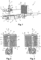
Fig. 1 ] lafigure 1 illustre une installation selon un premier mode de réalisation de l'invention, - [
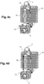
Fig. 2 ] lafigure 2 est une vue sensiblement de face du dispositif de l'installation illustrée à lafigure 1 , une bague du dispositif étant dans une première position, - [
Fig. 3 ] lafigure 3 est une vue similaire à celle de lafigure 2 , une bague du dispositif étant dans une deuxième position, - [
Fig. 4a ] lafigure 4a illustre une première étape de fixation du dispositif de maintien à un appareil de l'installation illustrée à lafigure 1 , - [
Fig. 4b ] lafigure 4b illustre une deuxième étape de fixation du dispositif de maintien à un appareil de l'installation illustrée à lafigure 1 , - [
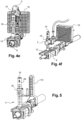
Fig. 4c ] lafigure 4c illustre une troisième étape de fixation du dispositif de maintien à un appareil de l'installation illustrée à lafigure 1 , - [
Fig. 4d ] lafigure 4d illustre une quatrième étape de fixation du dispositif de maintien à un appareil de l'installation illustrée à lafigure 1 , - [
Fig. 4e ] lafigure 4e illustre une cinquième étape de fixation du dispositif de maintien à un appareil de l'installation illustrée à lafigure 1 , - [
Fig. 4f ] lafigure 4f illustre une sixième étape de fixation du dispositif de maintien à un appareil de l'installation illustrée à lafigure 1 , - [
Fig. 5 ] lafigure 5 illustre une installation selon un deuxième mode de réalisation de l'invention, - [Fig. 6] la figure 6 illustre une installation selon un troisième mode de réalisation de l'invention.
- En référence aux
figures 1 à 3 , selon un premier mode de réalisation de l'invention, l'installation, généralement désignée en 1, comporte un dispositif de maintien 2 qui est associé à un instrument médical. L'instrument médical est ici un applicateur 3 pour un traitement par micro-ondes d'au moins une zone d'une prostate d'un patient et ce par une approche transpérinéale. - Cette application n'est bien entendu pas limitative et on pourra utiliser l'installation 1 comme le dispositif de maintien 2 en association avec différents types d'actes médicaux (biopsie, curiethérapie, cryothérapie, thérapie laser ...) ; différentes approches (transpérinéale, transrectale ...) et différentes cibles (prostate, rein, foie, utérus ...) .
- L'installation 1 comme le dispositif de maintien 2 pourront ainsi être associés à d'autres instruments que l'applicateur 3 comme par exemple un porte-aiguille à biopsie.
- Afin de pouvoir effectuer un traitement ciblé, l'applicateur 3 comporte notamment un manche 4 à partir duquel s'étend une aiguille 5 de traitement. Le manche 4 comporte par ailleurs un connecteur pour son rattachement à un câble stérile. Un tel applicateur 3 est bien connu de l'homme du métier et ne sera pas davantage détaillé ici.
- L'installation 1 comporte par ailleurs un appareil 6 de contrôle s'étendant généralement longitudinalement selon un axe Z afin de faciliter son insertion dans le rectum du patient.
- De préférence, l'appareil 6 comporte un support 7, s'étendant parallèlement à l'axe Z, qui est destiné à être saisi au niveau de son extrémité proximale par un opérateur et qui est prolongé à son extrémité distale par un décrochement 8 de l'appareil 2. Ledit décrochement 8 est lui-même prolongé par une sonde 9 d'imagerie médicale de l'appareil 2 pour permettre la génération d'images en trois dimensions de la prostate et de son environnement, sonde 9 s'étendant également selon l'axe Z. De la sorte, l'appareil 2 est plus aisément manipulable par l'opérateur du fait du décrochement 8.
- Pour faciliter le travail de l'opérateur, l'installation 1 peut comprendre un système de co-manipulation de l'appareil 6, lié à l'extrémité proximale de l'appareil 6. Le système de co-manipulation est par exemple un robot, un bras articulé ...
- La sonde 9 est ici une sonde échographique qui est donc destinée à être introduire dans le rectum du patient. Cette application n'est bien entendu pas limitative et on pourra utiliser le dispositif de maintien 2 avec d'autres types d'imageries i.e. d'autres types de sondes. L'installation 1 comporte de préférence un guide-aiguille 10 solidaire de l'appareil 6. Plus précisément ici, le guide-aiguille 10 est porté par la sonde 9. Le guide-aiguille 10 est donc agencé sur l'appareil 6 en aval du décrochement 8 (selon un sens allant du support 7 à la sonde 9).
- De préférence, le guide-aiguille 10 est monté coulissant sur la sonde 9 afin de pouvoir modifier sa position vis-à-vis du patient.
- Le guide-aiguille 10 comporte par ailleurs une grille qui s'étend ici dans un plan sensiblement de normale l'axe Z. La grille comporte des orifices 11 (une partie seulement est référencée ici), tous parallèles les uns aux autres, et à l'axe Z. Les différents orifices 11 sont par ailleurs agencés en colonnes sur la grille parallèlement à un axe X, orthogonal à l'axe Z et agencés en lignes sur la grille parallèlement à un axe Y, orthogonal à l'axe X et à l'axe Z.
- L'aiguille 5 peut ainsi être insérée dans le guide-aiguille 10 à une hauteur différente (selon l'axe X) ce qui permet de définir la hauteur à laquelle l'aiguille 5 vient s'enfoncer dans le périnée mais également à une largeur différente dans le guide-aiguille 10 (selon l'axe Y) ce qui permet de définir la distance à laquelle l'aiguille 5 vient s'enfoncer dans le périnée. On peut ainsi guider l'aiguille 5 tout en ayant une liberté selon deux degrés de liberté sur la zone d'insertion de l'aiguille 5 dans le périnée.
- Préférentiellement la grille elle-même comporte des repères graphiques (graduations, caractères alphanumériques ...) pour identifier les différentes colonnes d'orifices de la grille et des repères graphiques différents pour identifier les différentes lignes d'orifices de la grille. Optionnellement, la grille comporte des lettres pour identifier chaque colonne et des chiffres pour identifier chaque ligne.
- On va à présent s'attacher à décrire le dispositif de maintien 2.
- Le dispositif de maintien 2 comporte tout d'abord une base 12 qui est portée par l'appareil 6. Plus précisément ici, la base 12 est portée par le support 7. La base 12 se situe donc en amont du décrochement 8.
- La base 12 comporte un plateau 13 s'étendant sensiblement sur toute la longueur du support 7 parallèlement à l'axe Z.
- Par ailleurs, la base 12 comporte des moyens de fixation temporaire à l'appareil 6 comme des moyens d'encliquetage. La base 12 comporte de préférence une première paire de bras 14 et une deuxième paire de bras 15, les deux paires de bras étant agencées à des extrémités longitudinales opposées du plateau 13 pour l'encliquetage de la base 12 au support 7.
- La base 12 est donc ainsi directement portée par le support 7 sans élément intermédiaire.
- De préférence (comme plus visible à la
figure 4a ), la base 12 comporte un signe de repérage 14 permettant à l'opérateur de placer plus rapidement de manière correcte la base 12 sur le support 7. Par exemple le signe de repérage 14 est un élément graphique (ligne, flèche ...) symbolisant l'une des extrémités longitudinales du support 7, l'opérateur devant agencer la base 12 de manière que le signe de repérage 14 soit sensiblement à l'aplomb de ladite extrémité longitudinale. - Le dispositif de maintien 2 comporte en outre une structure porteuse comprenant ici une colonne 15 montée mobile sur la base 12 de manière à pouvoir se déplacer sur la base 12 entre une première position et une deuxième position. La première position est ici dite position de travail soit une position dans laquelle la colonne 15 est à niveau de l'applicateur 3, et plus exactement de son manche 4. La deuxième position est ici dite de manoeuvre soit une position dans laquelle la colonne 15 est éloignée de l'applicateur 3.
- La colonne 15 est ici (hors extrémité inférieure) de section circulaire.
- Optionnellement, la colonne 15 est montée coulissante sur la base 12 entre ces deux positions. A cet effet, l'extrémité inférieure de la colonne 15 est conformée en un socle 16 apte à coulisser dans une paire de rails 17 correspondants de la base 12. La colonne 15 est donc ainsi directement portée par la base 12 sans élément intermédiaire.
- La colonne 15, lorsqu'elle est montée sur la base 12, s'étend en conséquence sensiblement à la normale de la base 12. Dans le cas présent, la colonne 15 s'étend ainsi selon un axe C qui, en service, est parallèle à l'axe X, la colonne coulissant alors parallèlement à l'axe Z sur le support 7.
- Plus précisément ici, les rails 17 s'étendent longitudinalement parallèlement à l'axe Z sur une face supérieure du plateau 13 de sorte à border longitudinalement les deux côtés de ladite face.
- De préférence, les rails 17 s'étendent au moins jusqu'à l'une des extrémités longitudinales du plateau 13. Dans le cas présent, les rails 17 s'étendent jusqu'aux deux extrémités du plateau 13 de sorte à déboucher à leurs deux extrémités. Il est ainsi possible de séparément temporairement la colonne 15 du plateau 13 en faisant coulisser la colonne 15 jusqu'à l'une ou l'autre des extrémités longitudinales du plateau 13.
- Ceci facilite le montage du dispositif de maintien 2 et sa manipulation.
- De préférence alors, le socle 16 est conformé de manière que la colonne 15 ne puisse être insérée dans la base 12 que selon une seule orientation possible vis-à-vis de la base 12 ou que selon deux orientations possibles. Par exemple le socle 16 n'est pas conformé en un carré mais un rectangle de manière que le socle 16 ne puisse pas être introduit dans les rails 17 par ses deux plus grands côtés et/ou est conformé en un carré ne présentant des languettes aptes à coopérer avec les rails 17 que sur de seulement de ses côtés.
- De préférence, la structure porteuse comporte une bague 18 montée mobile sur la colonne 15. La bague 18 est directement portée par la colonne 15 sans élément intermédiaire.
- La bague 18 est ici montée coulissante sur la colonne 15.
- De façon préférée, la bague 18 est en outre agencée sur la colonne 15 de manière à pouvoir pivoter autour de l'axe C lorsque le dispositif de maintien 2 est en place sur l'appareil 6.
- La bague 18 peut ici pivoter à 360 degrés autour de la colonne 15 selon l'axe C.
- Typiquement, la bague 18 comporte un tube 19 de rattachement à la colonne 15. Le tube 19 s'étend selon une direction longitudinale et présente un orifice central coaxial à ladite direction, orifice traversant le tube 19 de part en part. Lorsque le tube 19 est monté sur la colonne 15, la direction longitudinale du tube est confondue avec la direction générale de la colonne 15 soit l'axe C. L'orifice présente une section similaire à celle de la colonne 15 pour autoriser le coulissement et la rotation de la bague 18 sur la colonne 15.
- Par ailleurs la bague 18 comporte des moyens de fixation temporaire de l'applicateur 3 à la bague 18, comme des moyens d'encliquetage 20.
- Les moyens d'encliquetage 20 sont portés par le tube 19 de sorte à s'étendre à côté du tube 19. Les moyens d'encliquetage 20 sont ainsi agencés en service à côté de la colonne 15 et non sur la colonne 15.
- Les moyens d'encliquetage 20 comportent de préférence une platine à partir de laquelle s'étendent latéralement deux bras pour l'encliquetage de l'applicateur 3 à la bague 18. L'applicateur 3 est ainsi directement porté par la bague 18 sans élément intermédiaire.
- Un des bras est ici fixé au tube 19. De préférence, le premier bras est fixé au tube 19 de sorte que le deuxième bras s'étende sensiblement parallèlement à l'axe C, et à distance de la colonne 15, lorsque la bague 18 est en place sur la colonne 15.
- Optionnellement le tube 19 et les moyens d'encliquetage 20 sont d'une seule pièce.
- Préférentiellement, la bague 18 comporte elle-même des repères graphiques associés aux repères graphiques des colonnes du guide-aiguille 10 dans le but de permettre d'orienter correctement le dispositif de maintien 2 vis-à-vis desdites colonnes du guide-aiguille 10.
- Dans le cas présent, et comme plus visible aux
figures 2 et 3 , la bague 18 comporte un premier repère graphique 21 sur un premier secteur angulaire du tube 19 et un deuxième repère graphique 22 sur un deuxième secteur angulaire du tube 19 opposé au premier secteur angulaire. - Le premier repère graphique 21 renvoie à la première moitié des repères graphiques des colonnes (ici en indiquant la première lettre et la dernière lettre de cette première moitié) et le deuxième repère graphique 22 renvoie à la deuxième moitié des repères graphiques des colonnes (ici en indiquant la première lettre et la deuxième lettre de cette deuxième moitié).
- De la sorte, une fois le dispositif de maintien 2 en place dans l'installation 1, selon que l'on place la bague 18 de manière que l'opérateur voit le premier repère graphique 21 ou le deuxième repère graphique 22, la bague 18 est tournée de 360 degrés ; et donc les moyens d'encliquetage 20 également. Le dispositif de maintien 2 est ainsi agencé de sorte que les moyens d'encliquetage 20 se trouvent soit à droite soit à gauche de la colonne 15 selon que le premier repère graphique 21 ou le deuxième repère graphique 22 fasse face à l'opérateur (bien entendu on se place dans la position de service usuelle dans laquelle l'opérateur tient le support 7 et regarde le guide-aiguille 10). Bien entendu les moyens d'encliquetage 20 de la bague 18 sont alors conformés de manière à pouvoir accueillir l'applicateur 3 que les moyens d'encliquetage 20 soient à gauche ou à droite de la colonne 15.
- En service, selon l'orientation de la bague 18 vis-à-vis de la colonne 15, l'applicateur 3 sera donc à droite ou à gauche de la colonne 15.
- Le dispositif de maintien 2 permet donc de faciliter la tâche de l'opérateur en portant l'applicateur 3 mais également en l'aidant à positionner le dispositif de maintien 2 vis-à-vis de l'applicateur 3 de manière relativement fine.
- Préférentiellement, le tube 19 est pourvu de deux fenêtres 23, 24 à travers lesquelles il est possible de visualiser la colonne 15, les deux fenêtres étant ménagées sur des secteurs annulaires opposés du tube 19. Au-dessus de chaque fenêtre 23, 24 est agencé l'un des repères graphiques 21, 22 de la bague 18.
- La colonne 15 comporte par ailleurs des repères graphiques le long de son axe C en relation avec ceux des lignes du guide-aiguille 10. Les repères graphiques sont donc ici une succession de chiffres.
- De la sorte, lorsque le tube 19 est déplacé le long de la colonne 15, il est possible de visualiser un repère graphique différent de la colonne 15 à travers l'une des fenêtres 23, 24.
- Dans le cas présent, la colonne 15 comporte autant de repères graphiques régulièrement répartis sur sa hauteur qu'il y a de lignes sur le guide-aiguille 10, à chaque repère graphique correspondant une des lignes du guide-aiguilles 10, à l'exception des deux lignes les plus basses qui sont regroupées sur un seul repère graphique.
- Optionnellement, le tube 19 comporte au moins un sigle de centrage 25, 26 associé à chaque fenêtre afin de placer le tube 19 de manière que le repère graphique visé de la colonne 15 soit bien placé au centre de la fenêtre 23, 24 considérée par l'opérateur. Chaque fenêtre 23, 24 est ici associée à deux traits appartenant à la même ligne horizontale médiane traversant ladite fenêtre 23, 24, les traits étant agencés de part et d'autre de ladite fenêtre 23, 24. D'autres sigles de centrage peuvent être employés comme un trait vertical, ou une ou des flèches, une ou des étoiles ...
- De préférence, chaque repère graphique de la colonne 15 est également associé à au moins un sigle de centrage 27 (une partie seulement étant référencée ici) afin de faciliter encore davantage le centrage de la fenêtre 23, 24 considérée sur le repère graphique de la colonne 15 visé. Typiquement chaque chiffre de la colonne 15 est entouré de deux traits appartenant à une même ligne horizontale. On choisit de préférence des fenêtres 23, 24 de dimensions suffisamment importantes de manière qu'au moins une partie des sigles de centrage 27 du repère visé de la colonne 15 soient visibles à travers la fenêtre 23, 24 considérée.
- Ainsi, l'opérateur peut plus facilement centrer la fenêtre 23, 24 sur le repère graphique visé.
- Le dispositif de maintien 2 permet donc de faciliter la tâche de l'opérateur en portant l'applicateur 3 mais également en l'aidant à positionner de manière fine, à la bonne hauteur, le dispositif de maintien 2 vis-à-vis de l'applicateur 3.
- Nous allons à présent décrire la manière dont le dispositif de maintien 2 est agencé dans l'installation 1 en référence aux
figures 4a à 4f . - En référence à la
figure 4a , la base 12 est encliquetée sur le support 7 puis la sonde 9 est insérée dans le rectum et positionnée selon une orientation et une position visées particulières en vue d'un traitement. - En référence à la
figure 4b , on vient alors monter la colonne 15 sur la base 12 en insérant le socle 16 dans les rails 17. On positionne également la bague 18 sur la colonne 15. - En référence à la
figure 4c , l'opérateur vient ensuite positionner l'applicateur 3 selon l'orientation et la position visées pour le traitement en s'aidant notamment du guide-aiguille. - Une fois l'aiguille 5 positionnée, il devient nécessaire de maintenir en place l'applicateur 3. A cet effet, l'opérateur oriente la bague 18 sur le côté droit si l'applicateur 3 est dans la partie droite du guide-aiguille 10 ou sur le côté gauche si l'applicateur 3 est dans la partie gauche du guide-aiguille 10. On voit bien ici l'intérêt des repères graphiques du dispositif de maintien 2 associés à ceux du guide-aiguille 10 qui facilitent le travail de l'opérateur.
- L'opérateur coulisse ensuite la colonne 15 sur la base 12 jusqu'au manche de l'applicateur 3.
- En référence à la
figure 4d , l'opérateur ajuste alors la hauteur de la bague 18 afin de se rapprocher de l'applicateur 3. Là encore, on voit bien l'intérêt des repères graphiques du dispositif de maintien 2. - En référence à la
figure 4e , l'opérateur vient encliqueter le manche 4 dans la bague 18. L'applicateur 3 est ainsi maintenu en place par le dispositif de maintien 2. - En référence à la
figure 4f , l'opérateur connecte l'applicateur 3 à un câble stérile pour débuter le traitement. - Le dispositif de maintien 2 ainsi décrit permet notamment bien que non exclusivement :
- de maintenir fixe la position de l'applicateur 3 et ce pendant les minutes ou dizaines de minutes que va durer le traitement,
- d'assurer un contrôle précis de la position de l'aiguille 5 en profondeur, le dispositif de maintien 2 empêchant un coulissement involontaire de l'applicateur 3 parallèlement à l'axe Z,
- de pouvoir en outre ajuster précisément la profondeur à laquelle l'aiguille 5 est insérée dans la prostate grâce au déplacement possible de l'applicateur 3 selon l'axe Z, l'opérateur pouvant ainsi contrôler avec précision l'insertion en profondeur (selon l'axe Z) de l'aiguille 5 en avançant sereinement l'applicateur 3 petit à petit (voir millimètre par millimètre) selon l'axe Z jusqu'à atteindre une cible visée,
- de laisser la possibilité à l'opérateur d'accéder malgré tout à l'ensemble du guide-aiguille 10 et donc à l'organe du fait notamment du montage ultérieur du dispositif de maintien 2 sur le support 6,
- d'être d'un encombrement réduit limitant ainsi un risque de gêne de l'opérateur durant le traitement,
- de pouvoir être placé mais aussi retiré de manière simple et rapide,
- d'être de construction simplifiée permettant une usinabilité aisée du dispositif.
- On remarque que le dispositif de maintien 2 permet de s'approcher finalement de l'applicateur 3 grâce à ses deux translations et sa rotation.
- Dans le cas présent, on profite avantageusement de la flexibilité de l'aiguille 5 pour ne permettre une orientation de la bague 18 que du côté gauche ou du côté droit de la colonne 15 (en place d'une translation complète parallèlement à l'axe Y). Comme indiqué ci-dessous on pourra toutefois prévoir que le dispositif de maintien 2 autorise une translation de la bague 18 selon l'axe Y pour s'approcher de manière encore plus fine de l'applicateur 3.
- Par ailleurs la construction simplifiée du dispositif permet de pouvoir construire très simplement le dispositif par exemple par moulage par injection ou bien par imprimante en trois dimensions. Dans le cas présent, la base 12, la colonne 15 et la bague 18 sont chacune moulées par injection.
- En référence à la
figure 5 , un deuxième mode de réalisation va être à présent décrit. - A la différence du premier mode de réalisation, le guide-aiguille 110 ne se présente pas sous la forme d'une grille mais d'un poteau. En conséquence, le guide-aiguille 110 ne comporte qu'une seule colonne d'orifices s'étendant selon l'axe X.
- Dans ce cas de figure, le dispositif de maintien peut alors être conformé différemment que dans le premier mode de réalisation avec une bague qui coulisse le long de la colonne sans toutefois pivoter autour de la colonne.
- Préférentiellement, on préfère utiliser malgré tout le même dispositif de maintien 2 que dans le premier mode de réalisation.
- De façon avantageuse, dans le cas où le guide-aiguille 110 n'utilise pas les mêmes repères graphiques que le guide-aiguille 10 du premier mode de réalisation, la colonne 15 est conformée pour présenter une première succession de repères graphiques correspondant au premier guide-aiguille 10 et une deuxième succession de repères graphiques correspondant au deuxième guide-aiguille 110, les deux successions de repère graphiques étant agencées sur des secteurs angulaires opposés de la colonne 15 à l'aplomb respectivement de l'un des deux côtés du socle 16 par lequel celui-ci peut être inséré dans les rails 17.
- De la sorte, selon que la colonne 15 est insérée par un premier côté du socle 16 dans les rails 17 ou par un deuxième côté, l'opérateur ne visualise pas la même succession de repères graphiques.
- Un même dispositif de maintien peut en conséquence être utilisé avec deux guides-aiguilles différents.
- Optionnellement, la colonne 15 comporte un premier élément de repérage 28 de la première succession de repères graphiques et un deuxième élément de repérage 29 de la deuxième succession de repères graphiques afin que l'opérateur puisse différencier plus facilement les deux successions de repères graphiques.
- Par exemple le premier élément de repérage 28 reproduit schématiquement une grille et le deuxième élément de repérage 29 reproduit schématique un poteau afin que l'opérateur puisse aisément associer le côté de la colonne 15 associé au bon guide-aiguille.
- En référence à la figure 6, un troisième mode de réalisation va être à présent décrit.
- A la différence du premier mode de réalisation, le guide-aiguille 210 ne se présente pas sous la forme d'une grille mais d'un tunnel. En conséquence, le guide-aiguille 210 ne comporte qu'un seul orifice.
- Dans ce cas de figure, le dispositif de maintien peut alors être conformé différemment que dans le premier mode de réalisation de manière que la structure porteuse ne comporte pas de colonne mais seulement une bague montée mobile sur la base.
- Dans le cas présent, la base 12 est identique à celles des autres modes de réalisation.
- De préférence, la bague 18 est également identique à celles des autres modes de réalisation.
- Ainsi, afin que la bague 18 coulisse sur la base 12 entre la position de travail dans laquelle la bague 18 est à niveau de l'applicateur 3, et plus exactement de son manche 4, et une position de manoeuvre dans laquelle la bague 18 est éloignée de l'applicateur 3, l'extrémité inférieure de la bague 18 est conformée en un socle 40 (plus visible aux
figures 4b et5 ) apte à coulisser dans la paire de rails 17 correspondants de la base 12. La bague 18 est donc ainsi directement portée par la base 12 sans élément intermédiaire. - Le socle 40 est ici agencé en partie basse des moyens d'encliquetage 20 et plus particulièrement de sa platine.
- Indifféremment, le socle 40 est conformé de manière que la bague 18 puisse être insérée dans la base 12 selon une seule orientation possible vis-à-vis de la base 12 ou selon deux orientations possibles. Par exemple le socle 40 n'est pas conformé en un carré mais un rectangle de manière que le socle 40 ne puisse pas être introduit dans les rails 17 par ses deux plus grands côtés et/ou est conformé en un carré ne présentant des languettes aptes à coopérer avec les rails 17 que sur de seulement de ses côtés.
- De façon avantageuse, en retirant la colonne 15 de la structure porteuse et en montant la bague 18 directement sur la base 12, le même dispositif de maintien peut ainsi être utilisé avec trois types de guide-aiguille différent.
- Bien entendu l'invention n'est pas limitée aux modes de réalisation décrits et on peut y apporter des variantes sans sortir du cadre de l'invention tel que défini par les revendications.
- En particulier, le dispositif de maintien pourra être utilisé pour d'autres applications que celles décrites. Notamment, le dispositif de maintien pourra être utilisé seul et non en association avec un guide-aiguille.
- Par ailleurs, l'installation pourra comporter un nombre différent d'instruments et/ou comporter des instruments différents de ce qui a été indiqué en fonction des applications visées. En fonction de l'application à laquelle sera destiné le dispositif de maintien, l'instrument pourra ainsi changer. L'instrument pourra être longiforme ou non. L'instrument pourra ainsi être un instrument de biopsie, de traitement, un instrument chirurgical, une aiguille, un applicateur, une fibre ... Si l'installation comporte au moins deux instruments, le dispositif pourra ainsi comporter au moins deux applicateurs de cryothérapie, au moins deux fibres laser ... On pourra alors avoir deux dispositifs de maintien, un pour chaque instrument, ou bien avoir un même dispositif de maintien portant les deux instruments.
- Le dispositif de maintien pourra être directement porté par la sonde d'imagerie médicale.
- Bien qu'ici la structure porteuse soit mobile sur la base selon un unique mouvement de translation, la structure porteuse pourra être montée sur la base selon un autre mouvement comme une ou plusieurs translations et/ou une ou plusieurs rotations.
- La structure porteuse pourra prendre une autre forme que celle décrite. Par exemple la structure porteuse pourra comporter une colonne présentant (hors socle d'attache à la base) une section ovale, carré, rectangulaire ... La structure porteuse pourra ne pas comporter de colonne. De la même manière, la structure porteuse pourra ne pas comporter de bague. La bague pourra être montée différemment sur la colonne. Par exemple la bague pourra n'être montée que pivotante selon la direction générale de la colonne porteuse ou n'être montée que coulissante le long de la colonne. La bague pourra être liée par une autre cinématique que celle décrite à la colonne. Par exemple la bague pourra être liée par une liaison rotule à la colonne ou bien par deux liaisons pivots ou bien par deux liaisons glissières. On pourra ainsi avoir une bague montée pivotante sur la colonne selon l'axe de colonne et selon un axe parallèle à l'axe X. On pourra avoir une bague montée en translation sur la colonne selon l'axe de colonne et selon un axe parallèle à l'axe X. La bague pourra avoir un nombre différent de fenêtres que ce qui a été indiqué et par exemple une seule fenêtre.
- La structure porteuse pourra être conformée de manière que ses éléments soient tous fixes entre eux.
- On pourra ainsi avoir un dispositif de maintien comprenant une structure porteuse montée mobile seulement en translation sur la base selon un seul axe de manière qu'une fois maintenu sur la structure porteuse l'instrument ne puisse être déplacé que selon ledit axe par un mouvement volontaire de l'opérateur. Ceci permettra ainsi de contrôler au moins la profondeur à laquelle l'instrument est positionné vis-à-vis du patient. Un tel dispositif est illustré à la figure 6.
- En cas de rotation d'un élément par rapport à un autre au sein du dispositif de maintien, la rotation pourra être complète (soit de 360 degrés) ou partielle.
- Les différentes étapes de montage du dispositif de maintien sur l'appareil pourront être différentes de ce qui a été indiqué. En particulier on pourra d'abord orienter grossièrement le dispositif de maintien vis-à-vis de l'instrument puis affiner au fur et à mesure le positionnement du dispositif de maintien vis-à-vis de l'instrument. En outre, bien qu'ici l'instrument soit déjà en place lorsqu'on le rattache au dispositif de maintien, l'instrument pourra n'être que partiellement en place ou non en place. On s'aidera alors du dispositif de maintien pour manipuler l'instrument grâce aux différentes orientations autorisées par les mouvements des éléments du dispositif de maintien entre eux.
- Bien qu'ici les différents éléments du dispositif de maintien soient mobiles entre eux de manière manuelle, un, plusieurs ou tous les mouvements pourront être motorisés.
- Bien qu'ici le simple frottement entre les différents éléments du dispositif de maintien suffise pour maintenir en place lesdits éléments relativement entre eux, le dispositif de maintien pourra comporter des moyens de fixation temporaires d'au moins deux éléments du dispositif de maintien entre eux (par exemple via des pions, des vis, des brides, par encliquetage ...)
- De la même manière, bien que les moyens de fixation décrits soit des moyens d'encliquetage, les moyens de fixation pourront être différents (par exemple des pions, des vis, des brides ...) .
Claims (18)
- Dispositif de maintien d'un instrument médical, le dispositif comprenant :- une base (12) destinée à être portée par un appareil (6) comprenant une sonde (9) d'imagerie médicale associée à l'instrument médical (3), et- une structure porteuse destinée à porter l'instrument médical et montée mobile sur la base de manière à pouvoir se déplacer sur la base entre une première position et une deuxième position,le dispositif étant apte à maintenir comme instrument médical un applicateur comprenant un manche (4) à partir duquel s'étend une aiguille (5) de traitement, la structure porteuse comprenant à cet effet une bague destinée à porter le manche de l'instrument médical.
- Dispositif selon la revendication 1, dans lequel la bague n'est pas portée par un porte-aiguille du dispositif.
- Dispositif selon la revendication 1 ou selon la revendication 2, dans lequel la structure porteuse est montée coulissante sur la base (12).
- Dispositif selon l'une des revendications 1 à 3, dans lequel la structure porteuse comporte une colonne (15) montée mobile sur la base et une bague (18) montée mobile sur la colonne.
- Dispositif selon la revendication 4, dans lequel la bague (18) est montée coulissante sur la colonne (15).
- Dispositif selon la revendication 4 ou la revendication 5, dans lequel la bague (18) est montée pivotante sur la colonne.
- Dispositif selon l'une des revendications 1 à 2 ou 4 à 6, dans lequel la bague (18) comporte des moyens de fixation temporaire de l'instrument au dispositif.
- Dispositif selon l'une des revendications 4 à 7, dans lequel la bague (18) comporte au moins une fenêtre (23, 24) pour visualiser la colonne.
- Dispositif selon l'une des revendications 4 à 8, dans lequel la bague (18) comporte au moins un sigle de repérage de l'orientation relative de la bague vis-à-vis de la colonne (15).
- Dispositif selon l'une des revendications 4 à 9, dans lequel la colonne (15) comporte au moins une succession de repères graphiques.
- Dispositif selon l'une des revendications 4 à 10, dans lequel la bague (18) est conformé pour pouvoir être montée mobile sur la base (12) sans la colonne (15).
- Dispositif selon l'une des revendications précédentes, dans lequel la structure porteuse peut être montée sur la base (12) selon au moins deux sens d'introduction différents.
- Dispositif selon la revendication 12, dans lequel la structure porteuse comporte un élément de repérage pour chaque sens d'introduction possible de la structure porteuse sur la base (12).
- Dispositif selon l'une des revendications précédentes, dans lequel la base (12) comporte au moins un signe de repérage pour symboliser où la base doit être montée en service sur l'appareil.
- Installation comprenant un dispositif selon l'une des revendications précédentes et un guide-aiguille (10 ; 110 ; 210).
- Installation selon la revendication 15, dans laquelle le guide-aiguille est une grille (10).
- Installation selon la revendication 15 ou la revendication 16, comportant en outre l'appareil qui comporte une sonde échographique.
- Installation selon l'une des revendications 15 à 17, comprenant en outre l'instrument médical qui n'est pas un guide-aiguille.
Applications Claiming Priority (2)
| Application Number | Priority Date | Filing Date | Title |
|---|---|---|---|
| FR1909085A FR3099695B1 (fr) | 2019-08-08 | 2019-08-08 | Dispositif de maintien d’un instrument médical et installation comprenant un tel dispositif |
| PCT/EP2020/072184 WO2021023838A1 (fr) | 2019-08-08 | 2020-08-06 | Dispositif de maintien d'un instrument medical et installation comprenant un tel dispositif |
Publications (3)
| Publication Number | Publication Date |
|---|---|
| EP4009878A1 EP4009878A1 (fr) | 2022-06-15 |
| EP4009878B1 true EP4009878B1 (fr) | 2024-02-28 |
| EP4009878C0 EP4009878C0 (fr) | 2024-02-28 |
Family
ID=69157955
Family Applications (1)
| Application Number | Title | Priority Date | Filing Date |
|---|---|---|---|
| EP20753348.0A Active EP4009878B1 (fr) | 2019-08-08 | 2020-08-06 | Dispositif de maintien d'un instrument medical et installation comprenant un tel dispositif |
Country Status (5)
| Country | Link |
|---|---|
| US (1) | US20220354455A1 (fr) |
| EP (1) | EP4009878B1 (fr) |
| JP (1) | JP7360536B2 (fr) |
| FR (1) | FR3099695B1 (fr) |
| WO (1) | WO2021023838A1 (fr) |
Families Citing this family (3)
| Publication number | Priority date | Publication date | Assignee | Title |
|---|---|---|---|---|
| WO2023213823A1 (fr) * | 2022-05-03 | 2023-11-09 | Faure Andre | Ensembles de positionnement d'instruments pour interventions percutanées |
| WO2024035897A2 (fr) * | 2022-08-11 | 2024-02-15 | Corbin Clinical Resources Llc | Dispositifs, systèmes et procédés d'utilisation de biopsie transpérinéale de la prostate |
| CN116636913A (zh) * | 2023-07-17 | 2023-08-25 | 陈慧娟 | 一种超声探头穿刺引导装置 |
Family Cites Families (14)
| Publication number | Priority date | Publication date | Assignee | Title |
|---|---|---|---|---|
| US4838506A (en) * | 1988-06-15 | 1989-06-13 | Cooper William I | Guidance device for ultrasound guided surgical procedures |
| US5494039A (en) * | 1993-07-16 | 1996-02-27 | Cryomedical Sciences, Inc. | Biopsy needle insertion guide and method of use in prostate cryosurgery |
| US5976092A (en) * | 1998-06-15 | 1999-11-02 | Chinn; Douglas O. | Combination stereotactic surgical guide and ultrasonic probe |
| US6095981A (en) * | 1998-07-01 | 2000-08-01 | The Regents Of The University Of California | Apparatus for attachment of needle or catheter to endoluminal ultrasound probe |
| WO2001087415A2 (fr) * | 2000-05-18 | 2001-11-22 | Integrated Implant Systems, L.L.C. | Appareil fixe de ciblage |
| US9655676B2 (en) * | 2003-05-16 | 2017-05-23 | Trod Medical | Method of percutaneous localized or focal treatment of prostate lesions using radio frequency |
| US10863970B2 (en) * | 2008-12-18 | 2020-12-15 | C. R. Bard, Inc. | Needle guide including enhanced visibility entrance |
| US9149251B2 (en) * | 2010-03-02 | 2015-10-06 | Civco Medical Instruments Co., Inc. | Hinged reusable endocavity needle guide |
| US10555719B2 (en) * | 2013-03-12 | 2020-02-11 | St. Jude Medical Puerto Rico Llc | Ultrasound assisted needle puncture mechanism |
| US20140343406A1 (en) * | 2013-05-15 | 2014-11-20 | LAD technology LLC | Needle positioning device for ultrasound-guided treatments and examinations |
| US10743909B2 (en) * | 2014-04-03 | 2020-08-18 | Corbin Clinical Resources, Llc | Transperineal prostate biopsy device, systems, and methods of use |
| EP3226785A1 (fr) * | 2014-12-01 | 2017-10-11 | Koninklijke Philips N.V. | Enregistrement d'outil de détection de forme optique |
| US10398526B2 (en) * | 2015-11-30 | 2019-09-03 | Trod Medical | Assembly for positioning electrodes for radiofrequency tissue ablation |
| CN209529192U (zh) | 2019-01-09 | 2019-10-25 | 于呈祥 | 一种ct刺穿的三维引导装置 |
-
2019
- 2019-08-08 FR FR1909085A patent/FR3099695B1/fr active Active
-
2020
- 2020-08-06 JP JP2022507649A patent/JP7360536B2/ja active Active
- 2020-08-06 US US17/633,400 patent/US20220354455A1/en not_active Abandoned
- 2020-08-06 EP EP20753348.0A patent/EP4009878B1/fr active Active
- 2020-08-06 WO PCT/EP2020/072184 patent/WO2021023838A1/fr not_active Ceased
Also Published As
| Publication number | Publication date |
|---|---|
| US20220354455A1 (en) | 2022-11-10 |
| JP7360536B2 (ja) | 2023-10-12 |
| FR3099695A1 (fr) | 2021-02-12 |
| JP2022543307A (ja) | 2022-10-11 |
| EP4009878C0 (fr) | 2024-02-28 |
| FR3099695B1 (fr) | 2022-11-25 |
| WO2021023838A1 (fr) | 2021-02-11 |
| EP4009878A1 (fr) | 2022-06-15 |
Similar Documents
| Publication | Publication Date | Title |
|---|---|---|
| WO2021023838A1 (fr) | Dispositif de maintien d'un instrument medical et installation comprenant un tel dispositif | |
| EP3684287B1 (fr) | Dispositif de guidage d'instrument | |
| EP2340781B1 (fr) | Procédé et appareil de localisation et de visualisation d'une cible par rapport à un point focal d'un système de traitement | |
| EP1983899B1 (fr) | Appareil de mise en place motorisée d'une aiguille | |
| EP2725961B1 (fr) | Instrument endoscopique a pied d'appui | |
| ES2908305T3 (es) | Magnetizador de agujas | |
| EP3927245B1 (fr) | Dispositif de guidage d'une aiguille médicale | |
| EP1607036A1 (fr) | Support d' instruments comprenant une bague et montable sur un endoscope | |
| WO2004080323A1 (fr) | Instrument medical localise a ecran orientable | |
| JP7506715B2 (ja) | 近位に取り付けられたカメラを備えるカニューレ | |
| EP3322347B1 (fr) | Systeme de guidage autonome d'un equipement porte-aiguille | |
| FR3089408A1 (fr) | Dispositif médical pour la chirurgie de l’oeil | |
| US11013402B2 (en) | Forward-imaging optical coherence tomography probe | |
| FR2991160A1 (fr) | Dispositif de guidage d'une sonde d'imagerie medicale, sonde d'imagerie medicale adaptee a etre guidee par un tel dispositif et procede de guidage d'une telle sonde. | |
| WO2019046158A1 (fr) | Dispositifs et procédés pour accéder à une cible à l'intérieur du corps | |
| WO2024188531A1 (fr) | Robot medical collaboratif pour securiser l'insertion d'instruments medicaux | |
| US10595712B2 (en) | Adaptive optical laser beam steering through endoscope for laser surgery in kidney | |
| EP2787895B1 (fr) | Dispositif d'assistance au positionnement d'un instrument medical relativement a un organe interne d'un patient | |
| WO2001026574A1 (fr) | Dispositif passif de localisation d'objet | |
| WO2024003421A1 (fr) | Guide pour instrument medical, ensemble d'un guide et d'un tel instrument, installation comprenant un tel ensemble | |
| US20200113613A1 (en) | Cryo needle guide | |
| US10022046B2 (en) | Multi-channel optical coherence tomography probe for use in a medical procedure | |
| FR3155419A1 (fr) | Stabilisateur d’aiguille pour une intervention médicale mini-invasive | |
| FR3078483A1 (fr) | Dispositif de traitement d'un tissu corporel | |
| Troccaz | Computer-and robot-assisted urological surgery |
Legal Events
| Date | Code | Title | Description |
|---|---|---|---|
| STAA | Information on the status of an ep patent application or granted ep patent |
Free format text: STATUS: UNKNOWN |
|
| STAA | Information on the status of an ep patent application or granted ep patent |
Free format text: STATUS: THE INTERNATIONAL PUBLICATION HAS BEEN MADE |
|
| PUAI | Public reference made under article 153(3) epc to a published international application that has entered the european phase |
Free format text: ORIGINAL CODE: 0009012 |
|
| STAA | Information on the status of an ep patent application or granted ep patent |
Free format text: STATUS: REQUEST FOR EXAMINATION WAS MADE |
|
| 17P | Request for examination filed |
Effective date: 20220202 |
|
| AK | Designated contracting states |
Kind code of ref document: A1 Designated state(s): AL AT BE BG CH CY CZ DE DK EE ES FI FR GB GR HR HU IE IS IT LI LT LU LV MC MK MT NL NO PL PT RO RS SE SI SK SM TR |
|
| DAV | Request for validation of the european patent (deleted) | ||
| DAX | Request for extension of the european patent (deleted) | ||
| GRAP | Despatch of communication of intention to grant a patent |
Free format text: ORIGINAL CODE: EPIDOSNIGR1 |
|
| STAA | Information on the status of an ep patent application or granted ep patent |
Free format text: STATUS: GRANT OF PATENT IS INTENDED |
|
| INTG | Intention to grant announced |
Effective date: 20231121 |
|
| GRAS | Grant fee paid |
Free format text: ORIGINAL CODE: EPIDOSNIGR3 |
|
| GRAA | (expected) grant |
Free format text: ORIGINAL CODE: 0009210 |
|
| STAA | Information on the status of an ep patent application or granted ep patent |
Free format text: STATUS: THE PATENT HAS BEEN GRANTED |
|
| AK | Designated contracting states |
Kind code of ref document: B1 Designated state(s): AL AT BE BG CH CY CZ DE DK EE ES FI FR GB GR HR HU IE IS IT LI LT LU LV MC MK MT NL NO PL PT RO RS SE SI SK SM TR |
|
| REG | Reference to a national code |
Ref country code: GB Ref legal event code: FG4D Free format text: NOT ENGLISH |
|
| REG | Reference to a national code |
Ref country code: CH Ref legal event code: EP |
|
| REG | Reference to a national code |
Ref country code: DE Ref legal event code: R096 Ref document number: 602020026460 Country of ref document: DE |
|
| REG | Reference to a national code |
Ref country code: IE Ref legal event code: FG4D Free format text: LANGUAGE OF EP DOCUMENT: FRENCH |
|
| U01 | Request for unitary effect filed |
Effective date: 20240311 |
|
| RAP4 | Party data changed (patent owner data changed or rights of a patent transferred) |
Owner name: KOELIS |
|
| REG | Reference to a national code |
Ref country code: CH Ref legal event code: PK Free format text: DIE PUBLIKATION VOM 27.03.2024 WURDE AM 24.04.2024 IRRTUEMLICHERWEISE ERNEUT PUBLIZIERT. LA PUBLICATION DU 27.03.2024 A ETE REPUBLIEE PAR ERREUR LE 24.04.2024. LA PUBBLICAZIONE DEL 27.03.2024 E STATA ERRONEAMENTE RIPUBBLICATA IL 24.04.2024. |
|
| U07 | Unitary effect registered |
Designated state(s): AT BE BG DE DK EE FI FR IT LT LU LV MT NL PT SE SI Effective date: 20240403 |
|
| PG25 | Lapsed in a contracting state [announced via postgrant information from national office to epo] |
Ref country code: IS Free format text: LAPSE BECAUSE OF FAILURE TO SUBMIT A TRANSLATION OF THE DESCRIPTION OR TO PAY THE FEE WITHIN THE PRESCRIBED TIME-LIMIT Effective date: 20240628 |
|
| PG25 | Lapsed in a contracting state [announced via postgrant information from national office to epo] |
Ref country code: GR Free format text: LAPSE BECAUSE OF FAILURE TO SUBMIT A TRANSLATION OF THE DESCRIPTION OR TO PAY THE FEE WITHIN THE PRESCRIBED TIME-LIMIT Effective date: 20240529 |
|
| PG25 | Lapsed in a contracting state [announced via postgrant information from national office to epo] |
Ref country code: RS Free format text: LAPSE BECAUSE OF FAILURE TO SUBMIT A TRANSLATION OF THE DESCRIPTION OR TO PAY THE FEE WITHIN THE PRESCRIBED TIME-LIMIT Effective date: 20240528 Ref country code: HR Free format text: LAPSE BECAUSE OF FAILURE TO SUBMIT A TRANSLATION OF THE DESCRIPTION OR TO PAY THE FEE WITHIN THE PRESCRIBED TIME-LIMIT Effective date: 20240228 |
|
| PG25 | Lapsed in a contracting state [announced via postgrant information from national office to epo] |
Ref country code: ES Free format text: LAPSE BECAUSE OF FAILURE TO SUBMIT A TRANSLATION OF THE DESCRIPTION OR TO PAY THE FEE WITHIN THE PRESCRIBED TIME-LIMIT Effective date: 20240228 |
|
| PG25 | Lapsed in a contracting state [announced via postgrant information from national office to epo] |
Ref country code: RS Free format text: LAPSE BECAUSE OF FAILURE TO SUBMIT A TRANSLATION OF THE DESCRIPTION OR TO PAY THE FEE WITHIN THE PRESCRIBED TIME-LIMIT Effective date: 20240528 Ref country code: NO Free format text: LAPSE BECAUSE OF FAILURE TO SUBMIT A TRANSLATION OF THE DESCRIPTION OR TO PAY THE FEE WITHIN THE PRESCRIBED TIME-LIMIT Effective date: 20240528 Ref country code: IS Free format text: LAPSE BECAUSE OF FAILURE TO SUBMIT A TRANSLATION OF THE DESCRIPTION OR TO PAY THE FEE WITHIN THE PRESCRIBED TIME-LIMIT Effective date: 20240628 Ref country code: HR Free format text: LAPSE BECAUSE OF FAILURE TO SUBMIT A TRANSLATION OF THE DESCRIPTION OR TO PAY THE FEE WITHIN THE PRESCRIBED TIME-LIMIT Effective date: 20240228 Ref country code: GR Free format text: LAPSE BECAUSE OF FAILURE TO SUBMIT A TRANSLATION OF THE DESCRIPTION OR TO PAY THE FEE WITHIN THE PRESCRIBED TIME-LIMIT Effective date: 20240529 Ref country code: ES Free format text: LAPSE BECAUSE OF FAILURE TO SUBMIT A TRANSLATION OF THE DESCRIPTION OR TO PAY THE FEE WITHIN THE PRESCRIBED TIME-LIMIT Effective date: 20240228 |
|
| PG25 | Lapsed in a contracting state [announced via postgrant information from national office to epo] |
Ref country code: PL Free format text: LAPSE BECAUSE OF FAILURE TO SUBMIT A TRANSLATION OF THE DESCRIPTION OR TO PAY THE FEE WITHIN THE PRESCRIBED TIME-LIMIT Effective date: 20240228 |
|
| PG25 | Lapsed in a contracting state [announced via postgrant information from national office to epo] |
Ref country code: PL Free format text: LAPSE BECAUSE OF FAILURE TO SUBMIT A TRANSLATION OF THE DESCRIPTION OR TO PAY THE FEE WITHIN THE PRESCRIBED TIME-LIMIT Effective date: 20240228 |
|
| U20 | Renewal fee for the european patent with unitary effect paid |
Year of fee payment: 5 Effective date: 20240827 |
|
| PG25 | Lapsed in a contracting state [announced via postgrant information from national office to epo] |
Ref country code: SM Free format text: LAPSE BECAUSE OF FAILURE TO SUBMIT A TRANSLATION OF THE DESCRIPTION OR TO PAY THE FEE WITHIN THE PRESCRIBED TIME-LIMIT Effective date: 20240228 |
|
| PG25 | Lapsed in a contracting state [announced via postgrant information from national office to epo] |
Ref country code: CZ Free format text: LAPSE BECAUSE OF FAILURE TO SUBMIT A TRANSLATION OF THE DESCRIPTION OR TO PAY THE FEE WITHIN THE PRESCRIBED TIME-LIMIT Effective date: 20240228 |
|
| PG25 | Lapsed in a contracting state [announced via postgrant information from national office to epo] |
Ref country code: SK Free format text: LAPSE BECAUSE OF FAILURE TO SUBMIT A TRANSLATION OF THE DESCRIPTION OR TO PAY THE FEE WITHIN THE PRESCRIBED TIME-LIMIT Effective date: 20240228 |
|
| PG25 | Lapsed in a contracting state [announced via postgrant information from national office to epo] |
Ref country code: SM Free format text: LAPSE BECAUSE OF FAILURE TO SUBMIT A TRANSLATION OF THE DESCRIPTION OR TO PAY THE FEE WITHIN THE PRESCRIBED TIME-LIMIT Effective date: 20240228 Ref country code: SK Free format text: LAPSE BECAUSE OF FAILURE TO SUBMIT A TRANSLATION OF THE DESCRIPTION OR TO PAY THE FEE WITHIN THE PRESCRIBED TIME-LIMIT Effective date: 20240228 Ref country code: RO Free format text: LAPSE BECAUSE OF FAILURE TO SUBMIT A TRANSLATION OF THE DESCRIPTION OR TO PAY THE FEE WITHIN THE PRESCRIBED TIME-LIMIT Effective date: 20240228 Ref country code: CZ Free format text: LAPSE BECAUSE OF FAILURE TO SUBMIT A TRANSLATION OF THE DESCRIPTION OR TO PAY THE FEE WITHIN THE PRESCRIBED TIME-LIMIT Effective date: 20240228 |
|
| REG | Reference to a national code |
Ref country code: DE Ref legal event code: R097 Ref document number: 602020026460 Country of ref document: DE |
|
| PLBE | No opposition filed within time limit |
Free format text: ORIGINAL CODE: 0009261 |
|
| STAA | Information on the status of an ep patent application or granted ep patent |
Free format text: STATUS: NO OPPOSITION FILED WITHIN TIME LIMIT |
|
| 26N | No opposition filed |
Effective date: 20241129 |
|
| REG | Reference to a national code |
Ref country code: CH Ref legal event code: PL |
|
| PG25 | Lapsed in a contracting state [announced via postgrant information from national office to epo] |
Ref country code: MC Free format text: LAPSE BECAUSE OF FAILURE TO SUBMIT A TRANSLATION OF THE DESCRIPTION OR TO PAY THE FEE WITHIN THE PRESCRIBED TIME-LIMIT Effective date: 20240228 Ref country code: CH Free format text: LAPSE BECAUSE OF NON-PAYMENT OF DUE FEES Effective date: 20240831 |
|
| PG25 | Lapsed in a contracting state [announced via postgrant information from national office to epo] |
Ref country code: IE Free format text: LAPSE BECAUSE OF NON-PAYMENT OF DUE FEES Effective date: 20240806 |
|
| U20 | Renewal fee for the european patent with unitary effect paid |
Year of fee payment: 6 Effective date: 20250827 |
|
| PGFP | Annual fee paid to national office [announced via postgrant information from national office to epo] |
Ref country code: GB Payment date: 20250820 Year of fee payment: 6 |
|
| PG25 | Lapsed in a contracting state [announced via postgrant information from national office to epo] |
Ref country code: CY Free format text: LAPSE BECAUSE OF FAILURE TO SUBMIT A TRANSLATION OF THE DESCRIPTION OR TO PAY THE FEE WITHIN THE PRESCRIBED TIME-LIMIT; INVALID AB INITIO Effective date: 20200806 |
|
| PG25 | Lapsed in a contracting state [announced via postgrant information from national office to epo] |
Ref country code: HU Free format text: LAPSE BECAUSE OF FAILURE TO SUBMIT A TRANSLATION OF THE DESCRIPTION OR TO PAY THE FEE WITHIN THE PRESCRIBED TIME-LIMIT; INVALID AB INITIO Effective date: 20200806 |