EP4010140B1 - Fraiseuse pour materiaux tendres et semi-tendre - Google Patents
Fraiseuse pour materiaux tendres et semi-tendre Download PDFInfo
- Publication number
- EP4010140B1 EP4010140B1 EP20765352.8A EP20765352A EP4010140B1 EP 4010140 B1 EP4010140 B1 EP 4010140B1 EP 20765352 A EP20765352 A EP 20765352A EP 4010140 B1 EP4010140 B1 EP 4010140B1
- Authority
- EP
- European Patent Office
- Prior art keywords
- cutting
- anterior
- milling bit
- spherical
- anterior part
- Prior art date
- Legal status (The legal status is an assumption and is not a legal conclusion. Google has not performed a legal analysis and makes no representation as to the accuracy of the status listed.)
- Active
Links
Images




Classifications
-
- B—PERFORMING OPERATIONS; TRANSPORTING
- B23—MACHINE TOOLS; METAL-WORKING NOT OTHERWISE PROVIDED FOR
- B23C—MILLING
- B23C5/00—Milling-cutters
- B23C5/02—Milling-cutters characterised by the shape of the cutter
- B23C5/10—Shank-type cutters, i.e. with an integral shaft
- B23C5/1009—Ball nose end mills
-
- B—PERFORMING OPERATIONS; TRANSPORTING
- B23—MACHINE TOOLS; METAL-WORKING NOT OTHERWISE PROVIDED FOR
- B23C—MILLING
- B23C2210/00—Details of milling cutters
- B23C2210/04—Angles
-
- B—PERFORMING OPERATIONS; TRANSPORTING
- B23—MACHINE TOOLS; METAL-WORKING NOT OTHERWISE PROVIDED FOR
- B23C—MILLING
- B23C2210/00—Details of milling cutters
- B23C2210/04—Angles
- B23C2210/0407—Cutting angles
- B23C2210/0442—Cutting angles positive
- B23C2210/0457—Cutting angles positive radial rake angle
-
- B—PERFORMING OPERATIONS; TRANSPORTING
- B23—MACHINE TOOLS; METAL-WORKING NOT OTHERWISE PROVIDED FOR
- B23C—MILLING
- B23C2210/00—Details of milling cutters
- B23C2210/04—Angles
- B23C2210/0485—Helix angles
-
- B—PERFORMING OPERATIONS; TRANSPORTING
- B23—MACHINE TOOLS; METAL-WORKING NOT OTHERWISE PROVIDED FOR
- B23C—MILLING
- B23C2210/00—Details of milling cutters
- B23C2210/08—Side or top views of the cutting edge
- B23C2210/084—Curved cutting edges
-
- B—PERFORMING OPERATIONS; TRANSPORTING
- B23—MACHINE TOOLS; METAL-WORKING NOT OTHERWISE PROVIDED FOR
- B23C—MILLING
- B23C2210/00—Details of milling cutters
- B23C2210/20—Number of cutting edges
- B23C2210/201—Number of cutting edges one
-
- B—PERFORMING OPERATIONS; TRANSPORTING
- B23—MACHINE TOOLS; METAL-WORKING NOT OTHERWISE PROVIDED FOR
- B23C—MILLING
- B23C2210/00—Details of milling cutters
- B23C2210/20—Number of cutting edges
- B23C2210/202—Number of cutting edges three
-
- B—PERFORMING OPERATIONS; TRANSPORTING
- B23—MACHINE TOOLS; METAL-WORKING NOT OTHERWISE PROVIDED FOR
- B23C—MILLING
- B23C2210/00—Details of milling cutters
- B23C2210/24—Overall form of the milling cutter
- B23C2210/241—Cross sections of the whole milling cutter
-
- B—PERFORMING OPERATIONS; TRANSPORTING
- B23—MACHINE TOOLS; METAL-WORKING NOT OTHERWISE PROVIDED FOR
- B23C—MILLING
- B23C2210/00—Details of milling cutters
- B23C2210/24—Overall form of the milling cutter
- B23C2210/246—Milling cutters comprising a hole or hollow in the end face or between the cutting edges
-
- B—PERFORMING OPERATIONS; TRANSPORTING
- B23—MACHINE TOOLS; METAL-WORKING NOT OTHERWISE PROVIDED FOR
- B23C—MILLING
- B23C2215/00—Details of workpieces
- B23C2215/08—Automotive parts
Definitions
- the invention relates to a soft and semisoft materials milling bit according to the preamble of claim 1.
- a soft and semisoft materials milling bit is known from US 6 234 725 B1 .
- CNC milling is a technology widely used in the field of automotive design, as well as in other areas of transportation and product design. This process allows the computer generated three-dimensional virtual models to materialize in full size by milling massive blocks of industrial clay.
- Industrial clay changes its physical characteristics in accordance with the temperature, from a soft plastic mass when heated to a state similar to hardened chocolate at room temperature.
- World automotive manufacturers use a vast quantity of clay milling equipment and rely on this technology for the manufacture of physical models with a high level of detail and realism. These models are of paramount importance for making the right design decisions when developing new models. In a highly competitive area of automotive design, it seems that in the foreseeable future, this technology will continue to be unique and irreplaceable as of today.
- a milling bit is known from US 6 234 725 B1 adapted for cutting an expanded synthetic resinous material such as a Styrofoam plastic.
- Said milling bit comprises an evacuation bore in a shank and generally radially extending passages opening to the bore to conduct away material being removed by cutters.
- the objective of the present invention is to provide a milling bit with a spherical ending that can form blocks of industrial clay into models by removing material in a stable and efficient way, with improved speed and surface quality regardless of changing cutting conditions.
- the improvement is achieved due to the specific geometry of the milling bit, which is adapted to the characteristics of the milling material.
- a soft and semisoft materials milling bit comprising the features of claim 1. Preferred embodiments of the present invention are defined in the dependent claims.
- the shape of the revolved surface described by at least one cutting edge of a tooth at the posterior part of the working sector may be cylindrical, conical, paraboloid, hyperboloid or a combination of the above.
- the cavity in the anterior part of the working sector extends partially to the posterior part of the working sector.
- the anterior cavity can be spherical, spheroidal, ellipsoidal, ovoid or other similar rotational shape.
- the diameter of the anterior part of the working sector is the same (inscribed) as the diameter of the posterior part, in which the anterior part is a hemisphere.
- the diameter of the anterior part of the working sector is larger than the diameter of the posterior part.
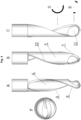
- the milling bit has one cutting tooth in the anterior part of the working sector, which is formed as a spherical shell element, representing a segment of a hollow sphere with an angular arc width ⁇ from 45° up to 180°, preferably from 60° to 180° in the Equatorial plane.
- the angular arc width ⁇ of the spherical shell element is 90° to 180°in the Equatorial plane, in the wall of the spherical shell element can be provided additional through hole.
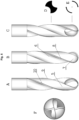
- the milling bit has three identical cutting teeth symmetrically arranged with respect to the Central axis of the milling bit, which in the anterior part of the working sector have the form of spherical shell elements representing segments of a hollow sphere with an angular arc width ⁇ from 10° to 45 in the Equatorial plane.
- Resistance when machining the clay is the result of wedging and cutting action of the cutting edges and the friction between deflective surfaces of the milling bit and the clay. Resistance exerted on the milling bit from the clay is proportional to the strength (toughness and hardness) of the clay and depends directly on the size and geometry of the milling bit, the speed of rotation and feed of the tool.
- the industrial clay being a plastic material, although cut off as chips has a tendency to adhere to deflective surfaces and drag, effect amplifying parasitic resistance and resulting negative consequences.
- the present invention goals the reduction of cutting resistance and consequently vibration and produced heat by changing the geometry of the milling bit. This can improve the speed and quality of cutting and hence the productivity of the entire process.
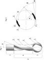
- the improved milling bit according to the invention is a soft and semisoft materials milling bit according to claim 1 with one or more cutting teeth 5 ( Fig. 1 ).
- the milling bit may include two integrally attached sections and subordinated to a single central axis of rotation as follows:
- the working sector 2 consists of:
- the number of the cutting teeth 5 can be one or more, respectively, the number of cutting edges 8 can be one or more. More cutting edges would mean presumably a higher cutting speed because there is less material to trim by one edge. On the other hand, more edges mean reducing the size of the flutes, respectively the space for the release of the chips, which could lead to accumulation of shavings, fusion and clutter. Therefore, the number of cutting edges between 1 and 5 is considered optimal.
- the cutting teeth 5 are no more than three.
- the forward part of the cutting 5 tooth of the milling bit ( Fig. 2 ) is formed as a straight or curved cutting wedge (cutting blade).
- Increasing the sharpness of the cutting wedge therefore decreasing the angle ⁇ of the wedge, diminishes deformation in the cut off layer, reduces cutting forces and generated heat.
- the section of the cutting blade is weakened, which leads to reduction of its strength. Therefore, the sharpness of the cutting part should be such as to ensure minimum cutting force with sufficient strength of the tool. This is achieved by selecting the appropriate geometric parameters of the cutting blade.
- the wedge part of the cutting tooth has three basic dimensions: length, width (thickness) and depth as the first two form a section area ( Fig. 2 ).
- the angle ⁇ is the angle enclosed between the outer deflecting surface of the cutting tooth and the motion vector of the cutting edge, which is tangent to the circle described by the cutting edge 8 during rotation. This angle can have values from 0° up to about 5°.
- the rake angle ( ⁇ on figure 2 ) is the angle of the cutting face relative to the normal to the cutting edge's motion vector. In the case of revolving tools, the normal is the radius of the motion circle. There are three types of rake angles: positive, zero or neutral, and negative. The positive rake angle means that the tool is sharper and pointed.
- Another improvement of the invention is facilitation the evacuation of the chips by means of a spherical cavity at the anterior part 3 of the working sector 2 and cavities along entire cutting sector 2 in some embodiments.
- the degree of reduction of the cutting tooth's blade section and deflecting angles depends on the milling bit's architecture and manufacturing technology.
- an essential feature of milling bit is that the anterior part 3 of the working sector 2 is hollow. Accordingly, the anterior cavity is formed by the inner surface of the tooth 5 or teeth and extends at least in the anterior part 3, but can also continue to the posterior part 4.
- the flutes 6 transit into the anterior cavity and together form the drainage space for the chips.
- the entire working sector 2 is hollow, and the deep channel 6 merges with the anterior cavity.
- the shape of the anterior cavity can be spherical, spheroidal, ellipsoidal, ovoid, cylindrical or other similar revolved shape or a combination thereof.
- the anterior cutting part 3 of the working sector 2 is a hollow sphere or a hemisphere reduced to one or more identical spherical shell elements 7 corresponding to the cutting teeth 5.
- Shell elements 7 are actually spherical segments of the theoretical sphere of the anterior part 3.
- the cutting edge 8 in the shell element 7 is a continuation of the projection of the helicoid forming the cutting edge 8 along its entire length.
- the thickness of the shell segments 7 is preferably 0.3 - 5 mm, and must meet the minimum strength parameters permitted by the implemented material and production technology. This allows a reduction in the thickness of the cutting teeth 5 at the anterior part and, accordingly, decrease of resistance.
- the shell elements 7 of the cutting teeth 5 in the anterior part 3, as spherical segments, may have different angular widths depending on the number of teeth 5.
- the angular width of the shell elements 7 represents the angle ⁇ between the end points of the cutting edge 8 and the trailing edge 9 of the shell element 7 and the center of the theoretical sphere of the anterior part 3, measured at the Equatorial plane of this imaginary sphere ( Fig. 2 ).
- an additional through hole 11 can be provided on the surface of the shell element 7 for better evacuation of chips (shavings).
- the additional hole 11 is perpendicular to the axis of rotation of the milling bit.
- the angular width ⁇ of the shell element 7 is important for the structural strength of the milling bit and particularly to the spherical anterior part 3 of the working sector 2.
- the angular width in the range of 100°- 180° gives good strength to the cutting shell (anterior cutting spherical segment), but reduces the evacuation of chips and is practically applicable when implemented with one anterior spherical cutting segment 7.
- the angular width ⁇ in the range of 10°- 90° gives a good release of chips, but would be structurally weak in execution with the individual cutting tooth.
- the shell element has angular arc width ⁇ about 45° - 190°, preferably about 60° - 180°degrees.
- Reducing the angular width ⁇ of the spherical shells 7 of the cutting teeth 5 also reduces the cutting resistance. This also facilitates the evacuation of chips.
- cutting teeth 5 are two or more, they are rotationally symmetrical relative to the axis of rotation of the tool, and accordingly, at equal peripheral distances from each other to ensure a uniform load on the tool body.
- the flutes 6 between the cutting teeth of the tool have the same size and shape, which ensures an equal distribution of chips.
- the diameter of the spherical anterior part 3 can be the same as the diameter of the posterior part (inscribed diameter) or could exceed the diameter of the posterior part 4.
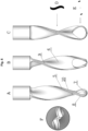
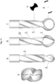
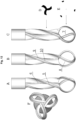
- the shape of the anterior part 3 is a hemisphere. Expressed geometrically, it is a union between a cylinder or other revolved geometric figure and a sphere of the same diameter ( Fig. 3 , 4 , 5 , 6 ). When the diameter of the anterior part 3 is greater than the diameter of the posterior part 4, then the shape of the anterior part 3 is a portion of a sphere larger than a hemisphere. Expressed geometrically, it is a union between a cylinder or other revolved geometric figure and a sphere of different diameters, the sphere being larger.
- the outmost diameter of the milling bit's anterior part can be from 2,5 mm to about 100 mm.
- the theoretical maximum size of the milling bit is not limited, but in practical terms, the size will be determined by the overall dimensions and details of the milled model. Larger cutters will have higher productivity. Too small milling bits will have reduced efficiency. Milling bits of a large diameter - 15-60 mm will cut material faster than a small 2.5-15 mm, so the largest that can do the task is preferred. When milling a concave shape (cavity), the diameter of the milling bit will be limited by the size of the internal curves.
- the radius of milling bit should be equal or smaller than the radius of the smallest negative geometric arc used in the virtual model.
- a negative radial indentation 10 ( Fig. 2 ).
- the maximum proportional difference between the diameter of the posterior part 4 and the diameter of the anterior spherical part 3 of the cutting sector 2 is preferable to be about 1:3.
- milling bits can be manufactured in one piece, composite and assembled. Milling bits can be made of one or more mechanically connected or welded elements in accordance with the production technology.
- the milling bits can be made of materials such as a tool steel and include wear-resistant inserts made of high-strength and hard synthetic materials. It is desirable that the surface of the tool is polished and coated with nonsticking layer.
- the milling bit After fixation in the chuck of the mill, the milling bit starts turning, and after reaching the operational revolutions, it enters the clay and is driven linearly along a pre-generated trajectory. Milling bit follows the linear trajectory via the theoretical centre of the spherical anterior part.
- the combination of rotational and translational movement of the tool in the material creates a cutting action.
- the process is subtractive, and as a result of the cutting action, the material is systematically cut off in the form of a channel with a section identical to the contour of the figure described by the cutting edges when the tool is rotated around the axis of rotation.
- the assembly of carved multiple parallel, overlapping and connected channels and cavities, whether shallow or deep forms the clay model surface.
Landscapes
- Engineering & Computer Science (AREA)
- Mechanical Engineering (AREA)
- Milling Processes (AREA)
Claims (10)
- Fraise à matériaux tendres et semi-tendres comprenant:- une tige (1) et- un secteur de travail (2) comprenant:dans lequel au moins la partie antérieure sphérique (3) de la section de travail (2) est creuse, caractérisé en ce qu'une cavité antérieure ouverte est formée par une surface interne de ladite au moins une dent coupante (5) qui dans la région de ladite cavité antérieure se présente sous la forme de un élément de coque sphérique (7) avec une épaisseur de paroi de 0,3 mm à 5 mm, dans lequel un angle de coin β est compris entre 3° et 40° à l'extrémité antérieure de la dent de coupe (5), dans lequel un angle d'inclinaison θ de la dent de coupe (5) au moins dans la partie antérieure du secteur de travail est compris entre 45° et 87°, dans lequel l'hélicoïde de formage de l'arête de coupe (8) a un angle hélicoïdal de 10° - 45°, de préférence de 20° à 35°.* une partie antérieure coupante (3) représentant une partie de sphere,* une partie postérieure coupante (4), fixée à la tige (1), située entre la tige (1) et la partie antérieure sphérique (3),* au moins une dent coupante (5), s'étendant sur toute la longueur de la secteur de travail, avec une arête de coupe (8) qui est formée comme une projection d'un hélicoïde sur la surface du secteur de travail (2) et se terminant à l'intersection de l'axe du trépan de fraisage et d'une surface sphérique avant de la partie antérieure (3),* au moins une cannelure hélicoïdale (6) à la dent de coupe (5) s'étendant le long de la longueur du secteur de travail (2) suivant le trajet de l'arête de coupe (8),
- Fraise selon la revendication 1, caractérisée en ce que la forme d'une surface tournante décrite par au moins un arête de coupe (8) de la dent coupante (5) au niveau de la partie postérieure (4) peut être cylindrique, conique, paraboloïde, hyperboloïde, ou une combinaison de ce qui precede.
- Fraise selon la revendication 1, caractérisée en ce que la cavité antérieure dans lela partie antérieure (3) du secteur de travail (2) s'étend partiellement jusqu'à la partie postérieure (4) du secteur de travail (2).
- Fraise selon l'une quelconque des revendications 1 à 3, caractérisée en ce que la cavité antérieure a une forme de rotation sphérique, sphéroïdale, elliptique, ovoïde ou autre similaire.
- Fraise selon l'une quelconque des revendications 1 à 4, caractérisée en ce que le diamètre de la partie antérieure (3) est le même que le diamètre de la partie postérieure (4), dans lequel la partie antérieure (3) est un hémisphère.
- Fraise selon l'une quelconque des revendications 1 à 4, caractérisée en ce que le diamètre de la partie antérieure (3) est supérieur au diamètre de la partie postérieure (4).
- Fraise selon l'une quelconque des revendications précédentes, caractérisée en ce que la partie antérieure (3) de la section de travail comporte une dent de coupe (5), qui est formée comme un élément de coque sphérique (7), représentant un segment d'une sphère creuse avec une largeur d'arc angulaire α dans le plan équatorial de 45° à 180°, de préférence de 60° à 180°.
- Fraise selon la revendication 7, caractérisée en ce que la largeur angulaire α dans le plan équatorial de l'arc de l'élément de coque sphérique (7) est de 90 ° à 180° et un trou traversant supplémentaire (11) est prévu dans la paroi de l'élément de coque sphérique (7).
- Fraise selon l'une quelconque des revendications 1 à 6, caractérisée en ce qu'il y a deux dents de coupe identiques diamétralement opposées (5), qui dans la partie antérieure (3) du secteur de travail (2) ont la forme d'éléments de coque sphériques (7), représentant segments d'une sphère creuse avec une largeur d'arc angulaire α dans le plan équatorial de 10° à 90°.
- Fraise selon l'une quelconque des revendications 1 à 6, caractérisée en ce qu'il y a trois dents de coupe identiques (5) disposées symétriquement par rapport à l'axe central de la fraise, lesdites dents de coupe (5) au niveau de la partie antérieure (3) du secteur de travail (2) ont la forme d'éléments de coque sphériques (7) représentant un segment d'une sphère creuse avec une largeur angulaire α de l'arc dans le plan équatorial de 10° à 45°.
Applications Claiming Priority (2)
| Application Number | Priority Date | Filing Date | Title |
|---|---|---|---|
| EP19472001 | 2019-08-09 | ||
| PCT/IB2020/057379 WO2021028781A1 (fr) | 2019-08-09 | 2020-08-05 | Mèche de fraisage à terminaison sphérique de fraisage à commande numérique d'argile industrielle |
Publications (3)
| Publication Number | Publication Date |
|---|---|
| EP4010140A1 EP4010140A1 (fr) | 2022-06-15 |
| EP4010140C0 EP4010140C0 (fr) | 2024-05-22 |
| EP4010140B1 true EP4010140B1 (fr) | 2024-05-22 |
Family
ID=68138003
Family Applications (1)
| Application Number | Title | Priority Date | Filing Date |
|---|---|---|---|
| EP20765352.8A Active EP4010140B1 (fr) | 2019-08-09 | 2020-08-05 | Fraiseuse pour materiaux tendres et semi-tendre |
Country Status (3)
| Country | Link |
|---|---|
| US (2) | US12440905B2 (fr) |
| EP (1) | EP4010140B1 (fr) |
| WO (1) | WO2021028781A1 (fr) |
Families Citing this family (1)
| Publication number | Priority date | Publication date | Assignee | Title |
|---|---|---|---|---|
| GB2586977B (en) * | 2019-09-10 | 2023-06-14 | Souber Tools Ltd | A burr |
Citations (2)
| Publication number | Priority date | Publication date | Assignee | Title |
|---|---|---|---|---|
| JP2001025912A (ja) * | 1999-07-15 | 2001-01-30 | Btt Kk | ボールエンドミル |
| WO2010050391A1 (fr) * | 2008-10-29 | 2010-05-06 | 住友電工ハードメタル株式会社 | Fraise à bout sphérique |
Family Cites Families (39)
| Publication number | Priority date | Publication date | Assignee | Title |
|---|---|---|---|---|
| US43673A (en) * | 1864-08-02 | Improvement in drills | ||
| DE485867C (de) * | 1927-12-23 | 1929-11-08 | Rueggeberg August Fa | Umlaufendes Werkzeug mit geschnittenen Zaehnen |
| US1717736A (en) * | 1928-10-24 | 1929-06-18 | Salstrom Carving Machine Compa | Carving-machine bit |
| FR667469A (fr) * | 1929-01-15 | 1929-10-17 | Gouge pour fabrication des sabots | |
| US2107787A (en) * | 1936-05-18 | 1938-02-08 | Earl W Grumke | Carving machine bit |
| US2202251A (en) * | 1937-04-17 | 1940-05-28 | Raymond G Gille | Wood carving tool |
| DE1779747A1 (de) | 1967-10-03 | 1971-04-01 | Ford Werke Ag | Schneidwerkzeug fuer weiche Materialien,insbesondere Ton |
| US3491651A (en) * | 1967-10-03 | 1970-01-27 | Ford Motor Co | Heated loop type cutter and controlled temperature spindle |
| JPS5253725A (en) * | 1975-10-28 | 1977-04-30 | Kobe Steel Ltd | Casting mold |
| US4265282A (en) * | 1979-11-13 | 1981-05-05 | Kurt Manufacturing Company, Inc. | Tubular rotating cutter |
| US4595321A (en) * | 1980-03-28 | 1986-06-17 | Leonard Van Dalen | Plug cutter |
| US4338050A (en) * | 1980-07-07 | 1982-07-06 | The Boeing Company | Method and tool for generating holes in composite materials |
| AU555566B2 (en) * | 1983-10-11 | 1986-10-02 | Vincent Sidney Smith | Woodturning tool |
| JPH05253725A (ja) * | 1992-03-10 | 1993-10-05 | Hitachi Tool Eng Ltd | エンドミル |
| JPH08168913A (ja) * | 1992-04-03 | 1996-07-02 | Hitachi Tool Eng Ltd | ボールエンドミル |
| DE4341325A1 (de) * | 1993-10-15 | 1995-04-20 | Marquardt Gmbh Geb | Verfahren und Vorrichtungen zur Herstellung von Gießmodellen |
| US5685671A (en) * | 1993-11-01 | 1997-11-11 | Smith International, Inc. | Diamond or CBN fluted center cutting end mill |
| JPH10263913A (ja) * | 1997-03-25 | 1998-10-06 | Hitachi Tool Eng Co Ltd | ボ−ルエンドミル |
| JPH10263914A (ja) * | 1997-03-28 | 1998-10-06 | Calsonic Corp | ボールエンドミル |
| DE19815269A1 (de) | 1998-04-04 | 1999-10-07 | Volkswagen Ag | Fräser zum Bearbeiten von Modelliermaterialien, insbesondere Industrieplastilin |
| US6234725B1 (en) * | 1999-12-14 | 2001-05-22 | Jonathan R. Campian | Rotary cutting tool |
| US20050133277A1 (en) * | 2003-08-28 | 2005-06-23 | Diamicron, Inc. | Superhard mill cutters and related methods |
| US7226249B2 (en) * | 2004-10-29 | 2007-06-05 | Mitsubishi Materials Corporation | Ball nose cutting insert and ball end mill thereof |
| DE102005002698B4 (de) * | 2005-01-19 | 2007-06-21 | Franken GmbH + Co KG Fabrik für Präzisionswerkzeuge | Fräswerkzeug |
| DE102007010163A1 (de) * | 2007-02-28 | 2008-09-04 | Sandvik Intellectual Property Ab | Kugelkopffräser |
| US20090022561A1 (en) * | 2007-07-18 | 2009-01-22 | Winebrenner John Richard | Rotary cutting tool |
| US20090053674A1 (en) * | 2007-08-22 | 2009-02-26 | Gebr. Brasseler Gmbh & Co. Kg | Dental drill |
| CN101386080B (zh) * | 2007-09-14 | 2011-12-21 | 鸿富锦精密工业(深圳)有限公司 | 铣刀 |
| FR2926480B1 (fr) * | 2008-01-23 | 2011-08-12 | Snecma | Fraise de surfacage et de detourage pour l'usinage a grande vitesse de pieces en materiau composite |
| JP2010105096A (ja) * | 2008-10-29 | 2010-05-13 | Sumitomo Electric Hardmetal Corp | 切屑回収式切削工具 |
| US8366354B2 (en) * | 2009-02-20 | 2013-02-05 | Kennametal Inc. | Rotary cutting tool with chip breaker pattern |
| WO2014030623A1 (fr) * | 2012-08-22 | 2014-02-27 | 田代精工株式会社 | Fraise à queue à rainurer et procédé de fabrication associé |
| US9636131B2 (en) * | 2013-03-15 | 2017-05-02 | Stryker Corporation | Surgical tool arrangement and surgical cutting accessory for use therewith |
| KR20150041850A (ko) * | 2013-10-10 | 2015-04-20 | (주)유엠 | 구형 회전 절삭공구 |
| JP6925260B2 (ja) * | 2014-08-14 | 2021-08-25 | ストライカー・ユーロピアン・ホールディングス・I,リミテッド・ライアビリティ・カンパニー | 単一切断フルートを有する外科用バー |
| US9643282B2 (en) * | 2014-10-17 | 2017-05-09 | Kennametal Inc. | Micro end mill and method of manufacturing same |
| CN104368859A (zh) * | 2014-10-31 | 2015-02-25 | 常州华尔澜工具有限公司 | 一种单刃刀 |
| US10189134B2 (en) * | 2016-12-08 | 2019-01-29 | GM Global Technology Operations LLC | Indexable plenum |
| CN207239249U (zh) * | 2017-09-06 | 2018-04-17 | 深圳市鑫国钰精密工具有限公司 | 圆鼻铣刀 |
-
2020
- 2020-08-05 EP EP20765352.8A patent/EP4010140B1/fr active Active
- 2020-08-05 WO PCT/IB2020/057379 patent/WO2021028781A1/fr not_active Ceased
-
2022
- 2022-02-09 US US17/668,302 patent/US12440905B2/en active Active
-
2025
- 2025-09-09 US US19/323,161 patent/US20260001149A1/en active Pending
Patent Citations (2)
| Publication number | Priority date | Publication date | Assignee | Title |
|---|---|---|---|---|
| JP2001025912A (ja) * | 1999-07-15 | 2001-01-30 | Btt Kk | ボールエンドミル |
| WO2010050391A1 (fr) * | 2008-10-29 | 2010-05-06 | 住友電工ハードメタル株式会社 | Fraise à bout sphérique |
Also Published As
| Publication number | Publication date |
|---|---|
| WO2021028781A1 (fr) | 2021-02-18 |
| US20220266357A1 (en) | 2022-08-25 |
| EP4010140A1 (fr) | 2022-06-15 |
| US20260001149A1 (en) | 2026-01-01 |
| EP4010140C0 (fr) | 2024-05-22 |
| US12440905B2 (en) | 2025-10-14 |
Similar Documents
| Publication | Publication Date | Title |
|---|---|---|
| EP2501511B1 (fr) | Géométrie d'arête de coupe dans des fraises en bout à nez arrondi | |
| EP2547268B1 (fr) | Mèche | |
| CN1315609C (zh) | 钻削或铣削刀具及其制造工艺 | |
| JP6993344B2 (ja) | 一体的に形成されたねじ付シャンクコネクタを備えた交換可能な正面フライスヘッド | |
| JP2010194712A (ja) | 金属製ワークピースの孔製作用のドリル工具 | |
| CN101511513B (zh) | 模块式钻孔工具及其制造方法 | |
| JP2011504818A (ja) | 超硬合金から成る回転バー | |
| JP2020514085A (ja) | ロータリー切削工具 | |
| JP7162657B2 (ja) | 金属切削のための旋削ツール及び方法 | |
| US20260001149A1 (en) | Milling bit with spherical ending for cnc milling of industrial clay | |
| US10525539B2 (en) | Compression milling cutter with indexable cutting inserts | |
| US20060045639A1 (en) | Multiple-axis cutting toroidal end mill | |
| JP3581115B2 (ja) | ボールエンドミル及び該ボールエンドミルを用いた加工方法 | |
| KR102740115B1 (ko) | 절삭 공구, 절삭 공구를 제조하기 위한 방법 및 가공물의 기계가공을 위한 방법 | |
| CN111230195A (zh) | 一种球头铣刀 | |
| JP7481617B2 (ja) | 加工方法および金型の製造方法 | |
| CN111344095B (zh) | 具有可变的刃圆曲度的螺纹刀片 | |
| JP7016212B2 (ja) | 複合型溝兼ねじ形成工具 | |
| JP2021506599A5 (ja) | バリアブルなエッジ丸みを有するスレッディングインサート | |
| JP7417112B2 (ja) | エンドミル | |
| JP7119933B2 (ja) | ボールエンドミル | |
| JP3318020B2 (ja) | ボールエンドミル | |
| JP2001009624A (ja) | エンドミル | |
| JPH0771770B2 (ja) | 転削工具 | |
| JP2024515236A (ja) | 先端部分が径方向延在切れ刃を有し、凹形及び凸形切削副部分を有する切削外形部を形成する、回転可能切削ヘッド |
Legal Events
| Date | Code | Title | Description |
|---|---|---|---|
| STAA | Information on the status of an ep patent application or granted ep patent |
Free format text: STATUS: UNKNOWN |
|
| STAA | Information on the status of an ep patent application or granted ep patent |
Free format text: STATUS: THE INTERNATIONAL PUBLICATION HAS BEEN MADE |
|
| PUAI | Public reference made under article 153(3) epc to a published international application that has entered the european phase |
Free format text: ORIGINAL CODE: 0009012 |
|
| STAA | Information on the status of an ep patent application or granted ep patent |
Free format text: STATUS: REQUEST FOR EXAMINATION WAS MADE |
|
| 17P | Request for examination filed |
Effective date: 20220302 |
|
| AK | Designated contracting states |
Kind code of ref document: A1 Designated state(s): AL AT BE BG CH CY CZ DE DK EE ES FI FR GB GR HR HU IE IS IT LI LT LU LV MC MK MT NL NO PL PT RO RS SE SI SK SM TR |
|
| DAV | Request for validation of the european patent (deleted) | ||
| DAX | Request for extension of the european patent (deleted) | ||
| GRAP | Despatch of communication of intention to grant a patent |
Free format text: ORIGINAL CODE: EPIDOSNIGR1 |
|
| STAA | Information on the status of an ep patent application or granted ep patent |
Free format text: STATUS: GRANT OF PATENT IS INTENDED |
|
| GRAJ | Information related to disapproval of communication of intention to grant by the applicant or resumption of examination proceedings by the epo deleted |
Free format text: ORIGINAL CODE: EPIDOSDIGR1 |
|
| STAA | Information on the status of an ep patent application or granted ep patent |
Free format text: STATUS: REQUEST FOR EXAMINATION WAS MADE |
|
| INTG | Intention to grant announced |
Effective date: 20231107 |
|
| GRAP | Despatch of communication of intention to grant a patent |
Free format text: ORIGINAL CODE: EPIDOSNIGR1 |
|
| STAA | Information on the status of an ep patent application or granted ep patent |
Free format text: STATUS: GRANT OF PATENT IS INTENDED |
|
| INTC | Intention to grant announced (deleted) | ||
| INTG | Intention to grant announced |
Effective date: 20231221 |
|
| GRAS | Grant fee paid |
Free format text: ORIGINAL CODE: EPIDOSNIGR3 |
|
| GRAA | (expected) grant |
Free format text: ORIGINAL CODE: 0009210 |
|
| STAA | Information on the status of an ep patent application or granted ep patent |
Free format text: STATUS: THE PATENT HAS BEEN GRANTED |
|
| RAP1 | Party data changed (applicant data changed or rights of an application transferred) |
Owner name: IVANOV, ANDREY ZHIVKOV |
|
| RIN1 | Information on inventor provided before grant (corrected) |
Inventor name: KAMENOV, KAMEN PETROV |
|
| AK | Designated contracting states |
Kind code of ref document: B1 Designated state(s): AL AT BE BG CH CY CZ DE DK EE ES FI FR GB GR HR HU IE IS IT LI LT LU LV MC MK MT NL NO PL PT RO RS SE SI SK SM TR |
|
| REG | Reference to a national code |
Ref country code: GB Ref legal event code: FG4D |
|
| REG | Reference to a national code |
Ref country code: CH Ref legal event code: EP |
|
| REG | Reference to a national code |
Ref country code: DE Ref legal event code: R096 Ref document number: 602020031321 Country of ref document: DE |
|
| REG | Reference to a national code |
Ref country code: IE Ref legal event code: FG4D |
|
| U01 | Request for unitary effect filed |
Effective date: 20240619 |
|
| U07 | Unitary effect registered |
Designated state(s): AT BE BG DE DK EE FI FR IT LT LU LV MT NL PT SE SI Effective date: 20240627 |
|
| U20 | Renewal fee for the european patent with unitary effect paid |
Year of fee payment: 5 Effective date: 20240627 |
|
| PG25 | Lapsed in a contracting state [announced via postgrant information from national office to epo] |
Ref country code: IS Free format text: LAPSE BECAUSE OF FAILURE TO SUBMIT A TRANSLATION OF THE DESCRIPTION OR TO PAY THE FEE WITHIN THE PRESCRIBED TIME-LIMIT Effective date: 20240922 |
|
| PG25 | Lapsed in a contracting state [announced via postgrant information from national office to epo] |
Ref country code: HR Free format text: LAPSE BECAUSE OF FAILURE TO SUBMIT A TRANSLATION OF THE DESCRIPTION OR TO PAY THE FEE WITHIN THE PRESCRIBED TIME-LIMIT Effective date: 20240522 |
|
| PG25 | Lapsed in a contracting state [announced via postgrant information from national office to epo] |
Ref country code: GR Free format text: LAPSE BECAUSE OF FAILURE TO SUBMIT A TRANSLATION OF THE DESCRIPTION OR TO PAY THE FEE WITHIN THE PRESCRIBED TIME-LIMIT Effective date: 20240823 |
|
| PG25 | Lapsed in a contracting state [announced via postgrant information from national office to epo] |
Ref country code: ES Free format text: LAPSE BECAUSE OF FAILURE TO SUBMIT A TRANSLATION OF THE DESCRIPTION OR TO PAY THE FEE WITHIN THE PRESCRIBED TIME-LIMIT Effective date: 20240522 |
|
| PG25 | Lapsed in a contracting state [announced via postgrant information from national office to epo] |
Ref country code: PL Free format text: LAPSE BECAUSE OF FAILURE TO SUBMIT A TRANSLATION OF THE DESCRIPTION OR TO PAY THE FEE WITHIN THE PRESCRIBED TIME-LIMIT Effective date: 20240522 |
|
| PG25 | Lapsed in a contracting state [announced via postgrant information from national office to epo] |
Ref country code: PL Free format text: LAPSE BECAUSE OF FAILURE TO SUBMIT A TRANSLATION OF THE DESCRIPTION OR TO PAY THE FEE WITHIN THE PRESCRIBED TIME-LIMIT Effective date: 20240522 Ref country code: NO Free format text: LAPSE BECAUSE OF FAILURE TO SUBMIT A TRANSLATION OF THE DESCRIPTION OR TO PAY THE FEE WITHIN THE PRESCRIBED TIME-LIMIT Effective date: 20240822 Ref country code: IS Free format text: LAPSE BECAUSE OF FAILURE TO SUBMIT A TRANSLATION OF THE DESCRIPTION OR TO PAY THE FEE WITHIN THE PRESCRIBED TIME-LIMIT Effective date: 20240922 Ref country code: HR Free format text: LAPSE BECAUSE OF FAILURE TO SUBMIT A TRANSLATION OF THE DESCRIPTION OR TO PAY THE FEE WITHIN THE PRESCRIBED TIME-LIMIT Effective date: 20240522 Ref country code: GR Free format text: LAPSE BECAUSE OF FAILURE TO SUBMIT A TRANSLATION OF THE DESCRIPTION OR TO PAY THE FEE WITHIN THE PRESCRIBED TIME-LIMIT Effective date: 20240823 Ref country code: ES Free format text: LAPSE BECAUSE OF FAILURE TO SUBMIT A TRANSLATION OF THE DESCRIPTION OR TO PAY THE FEE WITHIN THE PRESCRIBED TIME-LIMIT Effective date: 20240522 Ref country code: RS Free format text: LAPSE BECAUSE OF FAILURE TO SUBMIT A TRANSLATION OF THE DESCRIPTION OR TO PAY THE FEE WITHIN THE PRESCRIBED TIME-LIMIT Effective date: 20240822 |
|
| PG25 | Lapsed in a contracting state [announced via postgrant information from national office to epo] |
Ref country code: CZ Free format text: LAPSE BECAUSE OF FAILURE TO SUBMIT A TRANSLATION OF THE DESCRIPTION OR TO PAY THE FEE WITHIN THE PRESCRIBED TIME-LIMIT Effective date: 20240522 |
|
| PG25 | Lapsed in a contracting state [announced via postgrant information from national office to epo] |
Ref country code: RO Free format text: LAPSE BECAUSE OF FAILURE TO SUBMIT A TRANSLATION OF THE DESCRIPTION OR TO PAY THE FEE WITHIN THE PRESCRIBED TIME-LIMIT Effective date: 20240522 Ref country code: SK Free format text: LAPSE BECAUSE OF FAILURE TO SUBMIT A TRANSLATION OF THE DESCRIPTION OR TO PAY THE FEE WITHIN THE PRESCRIBED TIME-LIMIT Effective date: 20240522 |
|
| PG25 | Lapsed in a contracting state [announced via postgrant information from national office to epo] |
Ref country code: SM Free format text: LAPSE BECAUSE OF FAILURE TO SUBMIT A TRANSLATION OF THE DESCRIPTION OR TO PAY THE FEE WITHIN THE PRESCRIBED TIME-LIMIT Effective date: 20240522 |
|
| PG25 | Lapsed in a contracting state [announced via postgrant information from national office to epo] |
Ref country code: SM Free format text: LAPSE BECAUSE OF FAILURE TO SUBMIT A TRANSLATION OF THE DESCRIPTION OR TO PAY THE FEE WITHIN THE PRESCRIBED TIME-LIMIT Effective date: 20240522 Ref country code: SK Free format text: LAPSE BECAUSE OF FAILURE TO SUBMIT A TRANSLATION OF THE DESCRIPTION OR TO PAY THE FEE WITHIN THE PRESCRIBED TIME-LIMIT Effective date: 20240522 Ref country code: RO Free format text: LAPSE BECAUSE OF FAILURE TO SUBMIT A TRANSLATION OF THE DESCRIPTION OR TO PAY THE FEE WITHIN THE PRESCRIBED TIME-LIMIT Effective date: 20240522 Ref country code: CZ Free format text: LAPSE BECAUSE OF FAILURE TO SUBMIT A TRANSLATION OF THE DESCRIPTION OR TO PAY THE FEE WITHIN THE PRESCRIBED TIME-LIMIT Effective date: 20240522 |
|
| REG | Reference to a national code |
Ref country code: DE Ref legal event code: R097 Ref document number: 602020031321 Country of ref document: DE |
|
| PLBE | No opposition filed within time limit |
Free format text: ORIGINAL CODE: 0009261 |
|
| STAA | Information on the status of an ep patent application or granted ep patent |
Free format text: STATUS: NO OPPOSITION FILED WITHIN TIME LIMIT |
|
| REG | Reference to a national code |
Ref country code: CH Ref legal event code: PL |
|
| PG25 | Lapsed in a contracting state [announced via postgrant information from national office to epo] |
Ref country code: MC Free format text: LAPSE BECAUSE OF FAILURE TO SUBMIT A TRANSLATION OF THE DESCRIPTION OR TO PAY THE FEE WITHIN THE PRESCRIBED TIME-LIMIT Effective date: 20240522 Ref country code: CH Free format text: LAPSE BECAUSE OF NON-PAYMENT OF DUE FEES Effective date: 20240831 |
|
| 26N | No opposition filed |
Effective date: 20250225 |
|
| PG25 | Lapsed in a contracting state [announced via postgrant information from national office to epo] |
Ref country code: IE Free format text: LAPSE BECAUSE OF NON-PAYMENT OF DUE FEES Effective date: 20240805 |
|
| U20 | Renewal fee for the european patent with unitary effect paid |
Year of fee payment: 6 Effective date: 20250807 |
|
| PGFP | Annual fee paid to national office [announced via postgrant information from national office to epo] |
Ref country code: GB Payment date: 20250805 Year of fee payment: 6 |
|
| PG25 | Lapsed in a contracting state [announced via postgrant information from national office to epo] |
Ref country code: CY Free format text: LAPSE BECAUSE OF FAILURE TO SUBMIT A TRANSLATION OF THE DESCRIPTION OR TO PAY THE FEE WITHIN THE PRESCRIBED TIME-LIMIT; INVALID AB INITIO Effective date: 20200805 |
|
| PG25 | Lapsed in a contracting state [announced via postgrant information from national office to epo] |
Ref country code: HU Free format text: LAPSE BECAUSE OF FAILURE TO SUBMIT A TRANSLATION OF THE DESCRIPTION OR TO PAY THE FEE WITHIN THE PRESCRIBED TIME-LIMIT; INVALID AB INITIO Effective date: 20200805 |