EP4010151B1 - Configuration de dispositif robotique - Google Patents
Configuration de dispositif robotique Download PDFInfo
- Publication number
- EP4010151B1 EP4010151B1 EP20850343.3A EP20850343A EP4010151B1 EP 4010151 B1 EP4010151 B1 EP 4010151B1 EP 20850343 A EP20850343 A EP 20850343A EP 4010151 B1 EP4010151 B1 EP 4010151B1
- Authority
- EP
- European Patent Office
- Prior art keywords
- coupling member
- storage rack
- suction device
- robotic device
- suction
- Prior art date
- Legal status (The legal status is an assumption and is not a legal conclusion. Google has not performed a legal analysis and makes no representation as to the accuracy of the status listed.)
- Active
Links
Images




Classifications
-
- B—PERFORMING OPERATIONS; TRANSPORTING
- B25—HAND TOOLS; PORTABLE POWER-DRIVEN TOOLS; MANIPULATORS
- B25J—MANIPULATORS; CHAMBERS PROVIDED WITH MANIPULATION DEVICES
- B25J15/00—Gripping heads and other end effectors
- B25J15/0052—Gripping heads and other end effectors multiple gripper units or multiple end effectors
-
- B—PERFORMING OPERATIONS; TRANSPORTING
- B25—HAND TOOLS; PORTABLE POWER-DRIVEN TOOLS; MANIPULATORS
- B25J—MANIPULATORS; CHAMBERS PROVIDED WITH MANIPULATION DEVICES
- B25J15/00—Gripping heads and other end effectors
- B25J15/04—Gripping heads and other end effectors with provision for the remote detachment or exchange of the head or parts thereof
- B25J15/0408—Connections means
- B25J15/0433—Connections means having gripping members
-
- B—PERFORMING OPERATIONS; TRANSPORTING
- B25—HAND TOOLS; PORTABLE POWER-DRIVEN TOOLS; MANIPULATORS
- B25J—MANIPULATORS; CHAMBERS PROVIDED WITH MANIPULATION DEVICES
- B25J15/00—Gripping heads and other end effectors
- B25J15/04—Gripping heads and other end effectors with provision for the remote detachment or exchange of the head or parts thereof
- B25J15/0483—Gripping heads and other end effectors with provision for the remote detachment or exchange of the head or parts thereof with head identification means
-
- B—PERFORMING OPERATIONS; TRANSPORTING
- B25—HAND TOOLS; PORTABLE POWER-DRIVEN TOOLS; MANIPULATORS
- B25J—MANIPULATORS; CHAMBERS PROVIDED WITH MANIPULATION DEVICES
- B25J15/00—Gripping heads and other end effectors
- B25J15/04—Gripping heads and other end effectors with provision for the remote detachment or exchange of the head or parts thereof
- B25J15/0491—Gripping heads and other end effectors with provision for the remote detachment or exchange of the head or parts thereof comprising end-effector racks
-
- B—PERFORMING OPERATIONS; TRANSPORTING
- B25—HAND TOOLS; PORTABLE POWER-DRIVEN TOOLS; MANIPULATORS
- B25J—MANIPULATORS; CHAMBERS PROVIDED WITH MANIPULATION DEVICES
- B25J15/00—Gripping heads and other end effectors
- B25J15/06—Gripping heads and other end effectors with vacuum or magnetic holding means
- B25J15/0616—Gripping heads and other end effectors with vacuum or magnetic holding means with vacuum
-
- B—PERFORMING OPERATIONS; TRANSPORTING
- B25—HAND TOOLS; PORTABLE POWER-DRIVEN TOOLS; MANIPULATORS
- B25J—MANIPULATORS; CHAMBERS PROVIDED WITH MANIPULATION DEVICES
- B25J15/00—Gripping heads and other end effectors
- B25J15/08—Gripping heads and other end effectors having finger members
- B25J15/10—Gripping heads and other end effectors having finger members with three or more finger members
Definitions
- Embodiments described herein generally relate to robotic systems and methods and, more particularly but not exclusively, to systems and methods for configuring robotic devices.
- Logistic operations such as those in warehouse environments often include robotic devices to gather items from a first location (e.g., a container) and place the items at a second location (e.g., on a conveyor belt). Accordingly, these operations require the robotic device to first successfully grasp the item.
- Existing robotic devices often include a suction device that generates a suction force on an item to "grasp" the item.
- suction devices e.g., suction cups
- suction devices are configured for specific sizes or configurations of items. Accordingly, if a suction device is misconfigured, then the device may be unable to grasp an item and the picking operation would not be completed. This would halt the picking operation, and may require a human operator to intervene to pick-and-place the item.
- a first suction device may be unable to grasp an item
- another suction device e.g., a larger or smaller suction device
- a human operator would need to attach the second suction device to the robotic device. This would also contribute to downtime and inconvenience the human operator.
- US 2019/217471 discloses a robotic system comprising a tool rack for automatic change of the tool used by the robotic arm.
- inventions relate to a system for configuring a robotic device.
- the system includes a storage rack including a plurality of slots that are each configured to hold a first coupling member, wherein the first coupling member includes a first tool; and a robotic device configured with a second coupling member, wherein the second coupling member is configured to operably engage the first coupling member to remove the first coupling member and the first tool from the storage rack.
- the first tool is a first suction device.
- the robotic device is further configured to operably position the first coupling member at a first location on the storage rack and release the first coupling member and the first suction device on the storage rack, move to a third coupling member at a second location on the storage rack, wherein the third coupling member is configured with a second suction device, and operably engage the third coupling member using the second coupling member to remove the third coupling member and the second suction device from the storage rack.
- the first suction device and the second suction device are different types than each other, different sizes than each other, or have different levels of wear.
- the second coupling member includes an extension member with a seal component, the seal component creating a vacuum seal with the first coupling member upon the second coupling member engaging the first coupling member.
- the first tool includes a plurality of suction devices.
- the first coupling member is configured with an identification chip
- the storage rack is configured with at least one spring loaded pin
- the identification chip is configured to engage the at least one spring loaded pin upon insertion of the first coupling member at the storage rack to provide at least one of an electrical connection indicating that the first coupling member is positioned on the storage rack and a communication link with which to communicate data.
- the first coupling member is configured with at least one latch that is configured to hold the first coupling member in a closed position, and open the first coupling member upon being positioned on the storage rack to enable the first coupling member to receive the second coupling member.
- embodiments relate to a method for configuring a robotic device.
- the method includes operably positioning a robotic device with respect to a storage rack, wherein the storage rack holds at least one first coupling member configured with a first tool, and the robotic device includes a second coupling member, operably connecting the second coupling member to the first coupling member, and removing the first coupling member configured with the first tool from the storage rack.
- the first tool is a first suction device.
- the method further includes performing a first picking operation on a first item using the first suction device, and operably positioning the first coupling member at a location on the storage rack and releasing the first coupling member from the second coupling member.
- the method further includes operably connecting the second coupling member to a third coupling member on the storage rack, wherein the third coupling member is configured with a second suction device, removing the third coupling member configured with the second suction device from the storage rack, and performing a second picking operation on a second item using the second suction device.
- the first suction device and the second suction device are different types than each other, different sizes than each other, or have different levels of wear. In some embodiments, the first suction device is replaced by the second suction device based on a condition of the first suction device.
- inventions relate to a system for configuring a robotic device.
- the system includes a storage rack including a plurality of locations that are each configured to hold a tool, wherein the storage rack is configured to selectively receive a suction device at a location on the storage rack and selectively release the suction device upon engagement by a robotic device.
- the storage rack further includes at least one identification reader to detect a tool in a location.
- the system further includes a first coupling member operably configured to be received by the storage rack at a location, wherein the first coupling member is configured with the tool.
- the robotic device comprises a second coupling member, and the first coupling member is configured to operably connect with the second coupling member and be removed from the storage rack upon operably connecting with the second coupling member.
- the first coupling member includes at least one latch configured to secure the second coupling member to the first coupling member upon receiving the second coupling member.
- the storage rack is configured to hold suction devices of different sizes, different configurations, or different levels of wear.
- the robotic devices 106 may also include or otherwise be configured with force and torque-sensing abilities at the end effector to allow sensing tools to be effective. With this ability, the storage rack(s) and the robotic device can be automatically calibrated by having the robotic device approach and touch known geometry on the storage rack.
- FIG. 2 illustrates an exemplary robotic device 200 in accordance with one embodiment.
- the robotic device 200 may include an extension member 202 with one or more suction devices 204 attached thereto.
- the robotic device 200 may position itself sufficiently close to an item such that the suction device 204 may, via a generated suction force, come into contact with and stay in contact with the item.
- the robotic device 200 may also include a plurality of finger portions 206 to stabilize the item.
- FIG. 3 illustrates a robotic device 300 such as the picking device 200 of FIG. 2 interacting with a storage rack 302.
- the storage rack 302 may be similar to the storage rack 102 of FIG. 1 , for example.
- the storage rack 302 may include a plurality of locations such as slots that are able to hold or otherwise support suction devices. Each opening 304 may also be associated with one or more spring-loaded pins 306 such as the pins 110 of FIG. 1 . As discussed previously, these pins 306 may help identify when there is coupling member present in an opening 304 and also act as a link to exchange data and communications. As seen in FIG. 3 , suction devices 308 and 310 are positioned in openings 304 on the storage rack 302. Additionally, the robotic device 300 is seen as placing a suction device 312 into one of the openings 304. These suction devices are operably attached to coupling members, discussed below.
- the storage racks of the embodiments herein may include a "discard" slot with an optional receptacle.
- This discard slot may be configured with the storage rack or separate from the storage rack, and may receive broken or worn-out suction devices or tools.
- FIG. 4 illustrates front perspective view of a female coupling member 400 in accordance with one embodiment.
- the female coupling member 400 is operably configured with a suction device 402.
- the female coupling member 400 may include a top portion 404 that forms an aperture 406 configured to receive an extension component of a second coupling member (not shown in FIG. 4 ).
- the female coupling member 400 may include a pair of latches 408 that are rotationally pre-loaded about dowel pins 410 by spring 412 to be in a "closed” position. That is, the latches 408 are in this closed position when the female coupling member 400 is not in a storage rack.
- the female coupling member 400 may also include slot portion(s) 414 that slide along portions of a storage rack in order to store the female coupling member 400 on the storage rack. As the female coupling member 400 slides along these portions of the storage rack (such as at an opening 304 of FIG. 3 ), the storage rack will contact the latches 408. This contact creates a pinching force that compresses the spring 412, and opens the latches 408 to release or receive a male coupling member. This spring also provides some compliance in the case of a misalignment.
- the female coupling member 400 may include a mesh filter (e.g., made from stainless steel cloth) that stops larger particles and objects from traveling up the vacuum channel.
- the female coupling member 400 may also include features that securely mount selected suction devices such as a lip of a chosen diameter or a thread that can accept a suction device fitting.
- Some female coupling members may incorporate more than one mounting feature for increased versatility. For example, a single female coupling member may hold an array of suction devices.
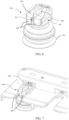
- FIG. 6 illustrates the female coupling member 400 of FIG. 4 without the top portion 404.
- the latches 408 would rotate about dowel pins 410 upon being inserted onto a storage rack. This would allow a male coupling member to be inserted into the aperture 406 to equip the male coupling member with the suction device 402 or to release a male coupling member from the first coupling member.
- FIG. 7 illustrates the female coupling member 400 of FIG. 6 operably positioned on a storage rack 702.
- the latches 408 have rotated to be in an open position.
- a second coupling member could then be inserted into or otherwise operably connect with the female coupling member 400.
- FIG. 8 illustrates a cross sectional view of a male coupling member 802 inserted into or otherwise operably connected with a female coupling member 804.
- the female coupling member 804 and the male coupling member 802 may be similar to those discussed previously.
- the male coupling member 802 may be configured with one or more compressed O-rings 806 to form a seal with the female coupling member 804..
- a sealed pneumatic channel 808 may run through the male coupling member 802 and female coupling member 804 to provide the suction force.
- the embodiments described herein use the maneuverability of the robotic device and its motion to achieve a suction device exchange by moving through prescribed motions to engage mechanisms of the coupling members that interact with mating geometry. As discussed above, this may be achieved through insertion of the male coupling member into an aperture on a female coupling member to move latches that rotate on axes parallel to the coupling axis.
- the latches of the female coupling member may slide linearly or rotate about axes that are not parallel to the coupling axis.
- the thickness of the storage rack (such as the storage rack 702 of FIG. 7 ) may be used to set the geometry for opening one or more latches.
- the storage rack geometry could axially compress a spring in a ball-lock style coupling to open the coupling for use in the same way as described above.
- the robotic device may rotate in order to open a coupling, similar to a bayonet style quick-disconnect fitting.
- rolling elements could be incorporated for use in place of sliding elements in order to reduce friction and wear. This could be desirable in applications in which the number of anticipated exchanges is very high.
- FIG. 9A illustrates a front perspective view of an assembly 900 of a female coupling member 902 and a male coupling member 904 in accordance with one embodiment.
- the female coupling member 902 is configured with a suction device 906.
- the suction device 906 may provide a suction force generated through aperture 908 via any suitable vacuum components (not shown in FIGS. 9A & B ).
- FIG. 9B illustrates a back perspective view of the assembly 900 of FIG. 9A in accordance with one embodiment.
- the female coupling member 902 includes a plurality of connectors 908 in operable communication with an identification chip (not shown in FIG. 9B ). These connectors 908 may contact the spring-loaded pins of a storage rack while the female coupling member 902 is secured on a storage rack to exchange data and communications. These communications may relate to the amount of time a particular female coupling member (and therefore a suction device) has been attached to the robotic device, as well as the number of picking operations performed by the suction device. The embodiments described herein may leverage this information to determine when it may be appropriate to replace a suction device with a new suction device (e.g., due to wear).
- FIG. 10 illustrates perspective view of a male coupling member 1000 in accordance with another embodiment.
- the male coupling member 1000 of FIG. 10 may include a plurality of ridges 1002 that are configured to engage an inner portion of a female coupling member, as well as one or more O-rings 1004 to at least help create a seal while the male coupling member 1000 remains inserted in a female coupling member.
- one or more O-rings can be configured with the female coupling member.
- the male coupling member 1000 may include a mounting screw 1006 to connect with a robotic device.
- the mounting screw 1006 may be held in place within the male coupling member 1000.
- Dowel pins 1008 may compactly hold the parts together.
- a splined female threaded shaft may fit into the housing 1010 to secure the mounting screw 1006 as it is fastened.
- a female hex drive may be incorporated into the mounting screw 1006 and readily accessible.
- a hex key may be pressed into the mounting screw 1006 and used to turn the mounting screw 1006 until the splined tube bottoms on the housing 1010, thereby compressing the O-ring(s) 1004 to a selected geometry to achieve a seal. Gaps in the housing 1010 allow visual inspection and verification.
- FIG. 11 illustrates a cross-sectional diagram of an assembly 1100 that includes the male coupling member 1000 of FIG. 10 inserted into a female coupling member 1102 that includes a suction device 1104.
- O-ring 1106 creates a seal between the female coupling member 1102 and the male coupling member 1000.
- the male coupling member 1000 of FIGS. 10 & 11 may be similar to the male coupling member of FIG. 8 with the exception of how it connects to the robotic device.
- dowel pins 1008 hold the various components of the assembly 1100 together.
- FIGS. 12A & B illustrate a robotic device 1200 performing a suction device exchange at a storage rack 1202. Specifically, FIG. 12A illustrates the robotic device 1200 moving towards opening 1204 to place a first female coupling member 1206 and a first suction device 1208 therein.
- FIG. 12B also shows a third female coupling member 1214 with a third suction device 1216.
- the third suction device 1216 is the same type of suction device as the first suction device 1208.
- a robotic device may need to replace one suction device with another of the same type, such as when the first suction device is broken, dirty, worn out, has fallen off the robotic device, or the like.
- the level of wear may be determined by, for example, imagery analysis, visual inspection, and/or based on knowledge regarding the number of picking operations performed.
- FIGS. 13A & B illustrate a bottom view of a portion of a storage rack 1300. More specifically, FIGS. 13A & B illustrate a female coupling member 1302 configured with a suction device 1304 being secured on the storage rack 1300. As seen in FIG. 13A , the female coupling member 1302 is secured in the storage rack 1300 by two spring-loaded pins 1306. These spring-loaded pins 1306 are secured on the storage rack by covers 1308 that are secured to the storage rack 1300 by bolts 1310. As the robotic device (not shown in FIGS.13A & B ) slides the female coupling member 1302 within the opening location 1312, the female coupling member 1302 applies a force to the spring-loaded pins 1306.
- FIG. 14 depicts a flowchart of a method 1400 for performing a picking operation in accordance with one embodiment.
- Method 1400 may be performed by the system of FIG. 1 , for example, as well as any of the components shown in the previous drawings.
- Step 1402 involves operably positioning a robotic device with respect to a storage rack, wherein the storage rack holds at least one first coupling member configured with a first tool, and the robotic device includes a second coupling member.
- the robotic device may be similar to the one shown in FIG. 2 , for example, and include a coupling member such as the male coupling member of FIG. 8 or FIG. 10 .
- the robotic device may be tasked with performing one or more picking operations and may need one or more suction devices to perform the picking operations.
- a statement that a value exceeds (or is more than) a first threshold value is equivalent to a statement that the value meets or exceeds a second threshold value that is slightly greater than the first threshold value, e.g., the second threshold value being one value higher than the first threshold value in the resolution of a relevant system.
- a statement that a value is less than (or is within) a first threshold value is equivalent to a statement that the value is less than or equal to a second threshold value that is slightly lower than the first threshold value, e.g., the second threshold value being one value lower than the first threshold value in the resolution of the relevant system.
Landscapes
- Engineering & Computer Science (AREA)
- Robotics (AREA)
- Mechanical Engineering (AREA)
- Manipulator (AREA)
Claims (13)
- Système (100) pour configurer un dispositif robotique (106), le système (100) comprenant :un support de stockage (102) comprenant une pluralité de fentes qui sont chacune configurées pour contenir un premier élément de couplage, dans lequel le premier élément de couplage comprend un premier outil ;
etun dispositif robotique (106) configuré avec un deuxième élément de couplage, dans lequel le deuxième élément de couplage est configuré pour s'engager de manière opérationnelle avec le premier élément de couplage afin de retirer le premier élément de couplage et le premier outil du support de stockage,caractérisé en ce que le premier élément de couplage est configuré avec une puce d'identification, le support de stockage (102) est configuré avec au moins une broche à ressort, et la puce d'identification est configurée pour s'engager avec la au moins une broche à ressort lors de l'insertion du premier élément de couplage au niveau du support de stockage (102) afin de fournir au moins l'une d'une connexion électrique indiquant que le premier élément de couplage est positionné sur le support de stockage (102) et d'une liaison de communication avec laquelle communiquer des données. - Système (100) selon la revendication 1 dans lequel le premier outil est un premier dispositif d'aspiration.
- Système (100) selon la revendication 2 dans lequel le dispositif robotique (106) est en outre configuré pour : positionner de manière opérationnelle le premier élément de couplage à un premier emplacement sur le support de stockage (102) et libérer le premier élément de couplage et le premier dispositif d'aspiration sur le support de stockage, se déplacer vers un troisième élément de couplage à un deuxième emplacement sur le support de stockage, le troisième élément de couplage étant configuré avec un deuxième dispositif d'aspiration, et engager de manière opérationnelle le troisième élément de couplage en utilisant le deuxième élément de couplage pour retirer le troisième élément de couplage et le deuxième dispositif d'aspiration du support de stockage.
- Système (100) selon la revendication 3 dans lequel le premier dispositif d'aspiration et le deuxième dispositif d'aspiration sont de types différents l'un de l'autre, de tailles différentes l'un de l'autre ou ont des niveaux d'usure différents.
- Système (100) selon la revendication 1 dans lequel le deuxième élément de couplage comprend un élément d'extension avec un composant d'étanchéité, le composant d'étanchéité créant un joint sous vide avec le premier élément de couplage lorsque le deuxième élément de couplage s'engage avec le premier élément de couplage.
- Système (100) selon la revendication 1, dans lequel le premier outil comprend une pluralité de dispositifs d'aspiration.
- Système (100) selon la revendication 1, dans lequel le premier élément de couplage est configuré avec au moins un loquet en position fermée lorsque le premier élément de couplage n'est pas dans le support de stockage.
- Système (100) selon les revendications 3 ou 4 dans lequel le premier dispositif d'aspiration et le deuxième dispositif d'aspiration sont de types différents l'un de l'autre, de tailles différentes l'un de l'autre ou ont des niveaux d'usure différents.
- Procédé de configuration d'un dispositif robotique (106), le procédé comprenant les étapes consistant à :positionner de manière opérationnel un dispositif robotique (106) par rapport à un support de stockage, dans lequel le support de stockage (102) contient au moins un premier élément de couplage configuré avec un premier outil, et le dispositif robotique (106) comprend un deuxième élément de couplage ; dans lequel le premier élément de couplage est configuré avec une puce d'identification, le support de stockage (102) est configuré avec au moins une broche à ressort, et la puce d'identification est configurée pour s'engager avec la au moins une broche à ressort lors de l'insertion du premier élément de couplage au niveau du support de stockage (102) afin de fournir au moins l'une d'une connexion électrique indiquant que le premier élément de couplage est positionné sur le support de stockage (102) et d'une liaison de communication avec laquelle communiquer des données ;connecter de manière opérationnelle le deuxième élément de couplage avec le premier élément de couplage ;et retirer le premier élément de couplage configuré avec le premier outil du support de stockage.
- Procédé selon la revendication 9, dans lequel le premier outil est un premier dispositif d'aspiration.
- Procédé selon la revendication 10, comprenant en outre l'exécution d'une première opération de prélèvement sur un premier article à l'aide du premier dispositif d'aspiration, et positionner de manière opérationnelle le premier élément de couplage à un emplacement sur le support de stockage (102) et libérer le premier élément de couplage du deuxième élément de couplage.
- Procédé selon la revendication 11, comprenant en outre les étapes consistant à :
connecter de manière opérationnelle le deuxième élément de couplage à un troisième élément de couplage sur le support de stockage, dans lequel le troisième élément de couplage est configuré avec un deuxième dispositif d'aspiration, retirer le troisième élément de couplage configuré avec le deuxième dispositif d'aspiration du support de stockage, et effectuer une deuxième opération de prélèvement sur un deuxième article en utilisant le deuxième dispositif d'aspiration. - Système (100) selon la revendication 1, dans lequel le support de stockage (102) comprend en outre au moins un lecteur d'identification pour détecter un outil dans un emplacement.
Applications Claiming Priority (2)
| Application Number | Priority Date | Filing Date | Title |
|---|---|---|---|
| US201962883689P | 2019-08-07 | 2019-08-07 | |
| PCT/US2020/039484 WO2021025800A1 (fr) | 2019-08-07 | 2020-06-25 | Configuration de dispositif robotique |
Publications (4)
| Publication Number | Publication Date |
|---|---|
| EP4010151A1 EP4010151A1 (fr) | 2022-06-15 |
| EP4010151A4 EP4010151A4 (fr) | 2023-08-16 |
| EP4010151C0 EP4010151C0 (fr) | 2025-04-02 |
| EP4010151B1 true EP4010151B1 (fr) | 2025-04-02 |
Family
ID=74503073
Family Applications (1)
| Application Number | Title | Priority Date | Filing Date |
|---|---|---|---|
| EP20850343.3A Active EP4010151B1 (fr) | 2019-08-07 | 2020-06-25 | Configuration de dispositif robotique |
Country Status (6)
| Country | Link |
|---|---|
| US (1) | US12311535B2 (fr) |
| EP (1) | EP4010151B1 (fr) |
| JP (1) | JP2022542782A (fr) |
| CN (1) | CN114174016A (fr) |
| CA (1) | CA3140155A1 (fr) |
| WO (1) | WO2021025800A1 (fr) |
Families Citing this family (15)
| Publication number | Priority date | Publication date | Assignee | Title |
|---|---|---|---|---|
| EP3341163B1 (fr) | 2015-08-26 | 2023-04-19 | Berkshire Grey Operating Company, Inc. | Systèmes et procédés de fourniture de détection de contact dans un bras articulé |
| ES2922990T3 (es) | 2016-01-08 | 2022-09-22 | Berkshire Grey Operating Company Inc | Sistemas de adquisición y movimiento de objetos |
| CN112752634B (zh) | 2018-07-27 | 2024-05-24 | 伯克希尔格雷营业股份有限公司 | 用于高效地交换端部执行器工具的系统和方法 |
| JP7676438B2 (ja) * | 2020-03-20 | 2025-05-14 | フューンボ テクノロジー アクティーゼルスカブ | 把持用工具、システムおよび挟持用工具、交換ステーションおよび該システムまたは挟持用工具を用いて物体をハンドリングする方法 |
| WO2022020178A1 (fr) | 2020-07-22 | 2022-01-27 | Berkshire Grey, Inc. | Systèmes et procédés de traitement d'objet en utilisant un dispositif de préhension à vide qui réalise une rétention d'objet par inversion d'enveloppe |
| CA3189565A1 (fr) | 2020-07-22 | 2022-01-27 | Berkshire Grey Operating Company, Inc. | Systemes et procedes de traitement d'objets a l'aide d'un dispositif de prehension a depression a affaissement passif |
| US11660761B2 (en) * | 2020-09-24 | 2023-05-30 | Gm Global Technology Operations, Llc | Flexible robotic system using end-effector with pass-through suction modules |
| US20230010426A1 (en) * | 2021-07-06 | 2023-01-12 | X Development Llc | Tool Rack For Interchangeable Robot Tools |
| TWI783779B (zh) | 2021-11-12 | 2022-11-11 | 財團法人工業技術研究院 | 訓練資料產生裝置、應用其之訓練資料產生方法及機械手臂系統 |
| TWI790025B (zh) * | 2021-12-06 | 2023-01-11 | 直得科技股份有限公司 | 機器手臂末端軸機械式自動換刀機構及方法 |
| CN117728247A (zh) * | 2022-05-16 | 2024-03-19 | 北京京东乾石科技有限公司 | 连接器、端拾器装置及分拣设备 |
| US12491680B2 (en) | 2022-11-10 | 2025-12-09 | The Gillette Company Llc | Method for forming gripper heads used to transport components |
| US12447630B2 (en) | 2022-11-10 | 2025-10-21 | The Gillette Company Llc | Kit for a gripper head apparatus for transporting components |
| SE2450748A1 (en) * | 2023-07-24 | 2025-01-25 | Tomra Sorting Gmbh | Automatic tool changer |
| US20260008187A1 (en) * | 2024-04-18 | 2026-01-08 | Dexterity, Inc. | Universal hub for robotic end effectors |
Family Cites Families (23)
| Publication number | Priority date | Publication date | Assignee | Title |
|---|---|---|---|---|
| US4604787A (en) * | 1984-08-15 | 1986-08-12 | Transamerica Delaval Inc. | Tool changer for manipulator arm |
| US4852242A (en) * | 1988-03-24 | 1989-08-01 | Hewlett-Packard Company | Tool coupling apparatus and method |
| US5044063A (en) * | 1990-11-02 | 1991-09-03 | The United States Of America As Represented By The Administrator Of The National Aeronautics And Space Administration | Robotic tool change mechanism |
| US5903457A (en) * | 1997-05-16 | 1999-05-11 | Moci Co., Ltd. | Automated material storage and retrieval system for production lines |
| US5993365A (en) * | 1998-03-26 | 1999-11-30 | Eastman Kodak Company | Tool attachment and release device for robotic arms |
| JP2992639B1 (ja) * | 1998-07-06 | 1999-12-20 | 工業技術院長 | 脱着機構 |
| US6321138B1 (en) * | 2000-09-15 | 2001-11-20 | Woodson Incorporated | Storage and retrieval system with automated order make up |
| DE10115467A1 (de) | 2001-03-29 | 2002-10-02 | Duerr Systems Gmbh | Werkzeugwechselsystem für eine Maschine |
| US6898484B2 (en) * | 2002-05-01 | 2005-05-24 | Dorothy Lemelson | Robotic manufacturing and assembly with relative radio positioning using radio based location determination |
| US7304855B1 (en) * | 2003-03-03 | 2007-12-04 | Storage Technology Corporation | Canister-based storage system |
| SE529377C2 (sv) * | 2005-10-18 | 2007-07-24 | Morphic Technologies Ab Publ | Metod och arrangemang för att lokalisera och plocka upp föremål från en bärare |
| US7825650B2 (en) * | 2006-12-15 | 2010-11-02 | Verigy (Singapore) Ptd. Ltd. | Automated loader for removing and inserting removable devices to improve load time for automated test equipment |
| US8992113B2 (en) * | 2009-06-08 | 2015-03-31 | Re2, Inc. | Robust manual connector for robotic arm end effector |
| US9272423B2 (en) * | 2010-12-22 | 2016-03-01 | Stratom, Inc. | Robotic tool interchange system |
| US10119642B2 (en) * | 2013-06-14 | 2018-11-06 | Intelligrated Headquarters, Llc | Vacuum coupling for robot arm |
| DE112014006251A5 (de) * | 2014-01-24 | 2016-10-06 | Stäubli-Tec Systems GmbH | Vorrichtung zum Kuppeln und mechanischen Verbinden einer ersten Komponente mit einer zweiten Komponente |
| JP6324210B2 (ja) | 2014-05-23 | 2018-05-16 | 株式会社大気社 | 塗装方法、及び、塗装設備 |
| JP6467040B2 (ja) * | 2015-02-16 | 2019-02-06 | ノルグレン オートメーション ソーリューションズ エルエルシーNorgren Automation Solutions,Llc. | モジュラー工作機械器具受容器 |
| KR102255834B1 (ko) * | 2015-03-20 | 2021-05-26 | 삼성전자주식회사 | 반도체 장치 및 이의 제조방법 |
| DE202015101616U1 (de) * | 2015-03-31 | 2016-07-04 | Kuka Systems Gmbh | Kupplungseinrichtung |
| CN105382845B (zh) * | 2015-12-23 | 2017-03-22 | 北京控制工程研究所 | 一种空间机械臂末端工具更换装置及更换方法 |
| DE102017121171A1 (de) * | 2017-09-13 | 2019-03-14 | Ferrobotics Compliant Robot Technology Gmbh | Verfahren und system zum automatischen wechseln von wellen |
| ES3042362T3 (en) * | 2018-01-17 | 2025-11-20 | Berkshire Grey Operating Company Inc | Systems and methods for efficiently moving a variety of objects |
-
2020
- 2020-06-25 EP EP20850343.3A patent/EP4010151B1/fr active Active
- 2020-06-25 CN CN202080052413.8A patent/CN114174016A/zh active Pending
- 2020-06-25 US US17/623,073 patent/US12311535B2/en active Active
- 2020-06-25 JP JP2021577406A patent/JP2022542782A/ja active Pending
- 2020-06-25 CA CA3140155A patent/CA3140155A1/fr active Pending
- 2020-06-25 WO PCT/US2020/039484 patent/WO2021025800A1/fr not_active Ceased
Also Published As
| Publication number | Publication date |
|---|---|
| EP4010151A1 (fr) | 2022-06-15 |
| CN114174016A (zh) | 2022-03-11 |
| JP2022542782A (ja) | 2022-10-07 |
| US20220266458A1 (en) | 2022-08-25 |
| EP4010151C0 (fr) | 2025-04-02 |
| EP4010151A4 (fr) | 2023-08-16 |
| CA3140155A1 (fr) | 2021-02-11 |
| US12311535B2 (en) | 2025-05-27 |
| WO2021025800A1 (fr) | 2021-02-11 |
Similar Documents
| Publication | Publication Date | Title |
|---|---|---|
| EP4010151B1 (fr) | Configuration de dispositif robotique | |
| JP7145843B2 (ja) | ロボットマニピュレータの訓練 | |
| US20220032463A1 (en) | Item perturbation for picking operations | |
| US11642797B2 (en) | Gripper apparatus for grasping objects | |
| DE102015115115B4 (de) | Gegenstandsaufnahmevorrichtung zum Aufnehmen von zufällig gehäuften Gegenständen | |
| CN117157616A (zh) | 用于机器人水平分拣的系统和方法 | |
| US20200039745A1 (en) | Automated item-level order fulfillment | |
| US20230106572A1 (en) | Systems and methods for dynamic processing of objects provided in vehicles with dual function end effector tools | |
| US20080019810A1 (en) | Overhead transfer flange and support for suspending a substrate carrier | |
| CN210339565U (zh) | 自动导引运输车、机器人及其夹持装置 | |
| FR3032365A1 (fr) | Procedure de tri selectif | |
| FR2848697A1 (fr) | Vetement identificateur d'objets a trier | |
| CN115676194B (zh) | 货物处理方法、装置、机器人、分拣装置及仓储系统 | |
| AU2015282762B2 (en) | Automated specimen processing systems and methods | |
| US11951612B2 (en) | Soft picking tools for pick and place robotic systems | |
| Han et al. | Towards mobile multi-task manipulation in a confined and integrated environment with irregular objects | |
| CN109465205A (zh) | 一种基于视觉识别技术的动态分拣系统和分拣方法 | |
| US12285856B2 (en) | End effector tool changer for robotic systems | |
| Xiang et al. | Classification-design-optimization integrated picking robots: a review | |
| HUE034387T2 (en) | Laboratory sample carrier tray and follow-up procedure | |
| Wurll et al. | Production logistics with mobile robots | |
| US20200225252A1 (en) | Sample container loading or storing unit and sample test automation system provided with same | |
| CN113298877B (zh) | 物体装配方法及装置 | |
| CN210876335U (zh) | 一种分拣输送系统 | |
| EP4412935A1 (fr) | Systèmes et procédés de traitement dynamique d'objets fournis dans des véhicules à remédiation d'obstruction |
Legal Events
| Date | Code | Title | Description |
|---|---|---|---|
| STAA | Information on the status of an ep patent application or granted ep patent |
Free format text: STATUS: THE INTERNATIONAL PUBLICATION HAS BEEN MADE |
|
| PUAI | Public reference made under article 153(3) epc to a published international application that has entered the european phase |
Free format text: ORIGINAL CODE: 0009012 |
|
| STAA | Information on the status of an ep patent application or granted ep patent |
Free format text: STATUS: REQUEST FOR EXAMINATION WAS MADE |
|
| 17P | Request for examination filed |
Effective date: 20211112 |
|
| AK | Designated contracting states |
Kind code of ref document: A1 Designated state(s): AL AT BE BG CH CY CZ DE DK EE ES FI FR GB GR HR HU IE IS IT LI LT LU LV MC MK MT NL NO PL PT RO RS SE SI SK SM TR |
|
| DAV | Request for validation of the european patent (deleted) | ||
| DAX | Request for extension of the european patent (deleted) | ||
| P01 | Opt-out of the competence of the unified patent court (upc) registered |
Effective date: 20230602 |
|
| A4 | Supplementary search report drawn up and despatched |
Effective date: 20230714 |
|
| RIC1 | Information provided on ipc code assigned before grant |
Ipc: B25J 15/10 20060101ALI20230710BHEP Ipc: B25J 15/06 20060101ALI20230710BHEP Ipc: B25J 15/04 20060101ALI20230710BHEP Ipc: B65G 47/90 20060101ALI20230710BHEP Ipc: B25J 15/00 20060101ALI20230710BHEP Ipc: B25J 13/02 20060101AFI20230710BHEP |
|
| GRAP | Despatch of communication of intention to grant a patent |
Free format text: ORIGINAL CODE: EPIDOSNIGR1 |
|
| STAA | Information on the status of an ep patent application or granted ep patent |
Free format text: STATUS: GRANT OF PATENT IS INTENDED |
|
| RIC1 | Information provided on ipc code assigned before grant |
Ipc: B25J 15/10 20060101ALI20241030BHEP Ipc: B25J 15/06 20060101ALI20241030BHEP Ipc: B25J 15/04 20060101ALI20241030BHEP Ipc: B65G 47/90 20060101ALI20241030BHEP Ipc: B25J 15/00 20060101ALI20241030BHEP Ipc: B25J 13/02 20060101AFI20241030BHEP |
|
| INTG | Intention to grant announced |
Effective date: 20241113 |
|
| GRAS | Grant fee paid |
Free format text: ORIGINAL CODE: EPIDOSNIGR3 |
|
| GRAA | (expected) grant |
Free format text: ORIGINAL CODE: 0009210 |
|
| STAA | Information on the status of an ep patent application or granted ep patent |
Free format text: STATUS: THE PATENT HAS BEEN GRANTED |
|
| RAP3 | Party data changed (applicant data changed or rights of an application transferred) |
Owner name: RIGHTHAND ROBOTICS, INC. |
|
| AK | Designated contracting states |
Kind code of ref document: B1 Designated state(s): AL AT BE BG CH CY CZ DE DK EE ES FI FR GB GR HR HU IE IS IT LI LT LU LV MC MK MT NL NO PL PT RO RS SE SI SK SM TR |
|
| REG | Reference to a national code |
Ref country code: GB Ref legal event code: FG4D |
|
| REG | Reference to a national code |
Ref country code: CH Ref legal event code: EP |
|
| REG | Reference to a national code |
Ref country code: IE Ref legal event code: FG4D |
|
| REG | Reference to a national code |
Ref country code: DE Ref legal event code: R096 Ref document number: 602020048867 Country of ref document: DE |
|
| U01 | Request for unitary effect filed |
Effective date: 20250424 |
|
| P04 | Withdrawal of opt-out of the competence of the unified patent court (upc) registered |
Free format text: CASE NUMBER: APP_20001/2025 Effective date: 20250425 |
|
| U07 | Unitary effect registered |
Designated state(s): AT BE BG DE DK EE FI FR IT LT LU LV MT NL PT RO SE SI Effective date: 20250430 |
|
| U20 | Renewal fee for the european patent with unitary effect paid |
Year of fee payment: 6 Effective date: 20250626 |
|
| PG25 | Lapsed in a contracting state [announced via postgrant information from national office to epo] |
Ref country code: ES Free format text: LAPSE BECAUSE OF FAILURE TO SUBMIT A TRANSLATION OF THE DESCRIPTION OR TO PAY THE FEE WITHIN THE PRESCRIBED TIME-LIMIT Effective date: 20250402 |
|
| PG25 | Lapsed in a contracting state [announced via postgrant information from national office to epo] |
Ref country code: NO Free format text: LAPSE BECAUSE OF FAILURE TO SUBMIT A TRANSLATION OF THE DESCRIPTION OR TO PAY THE FEE WITHIN THE PRESCRIBED TIME-LIMIT Effective date: 20250702 Ref country code: GR Free format text: LAPSE BECAUSE OF FAILURE TO SUBMIT A TRANSLATION OF THE DESCRIPTION OR TO PAY THE FEE WITHIN THE PRESCRIBED TIME-LIMIT Effective date: 20250703 |
|
| PG25 | Lapsed in a contracting state [announced via postgrant information from national office to epo] |
Ref country code: PL Free format text: LAPSE BECAUSE OF FAILURE TO SUBMIT A TRANSLATION OF THE DESCRIPTION OR TO PAY THE FEE WITHIN THE PRESCRIBED TIME-LIMIT Effective date: 20250402 |
|
| PG25 | Lapsed in a contracting state [announced via postgrant information from national office to epo] |
Ref country code: HR Free format text: LAPSE BECAUSE OF FAILURE TO SUBMIT A TRANSLATION OF THE DESCRIPTION OR TO PAY THE FEE WITHIN THE PRESCRIBED TIME-LIMIT Effective date: 20250402 |
|
| PG25 | Lapsed in a contracting state [announced via postgrant information from national office to epo] |
Ref country code: RS Free format text: LAPSE BECAUSE OF FAILURE TO SUBMIT A TRANSLATION OF THE DESCRIPTION OR TO PAY THE FEE WITHIN THE PRESCRIBED TIME-LIMIT Effective date: 20250702 |
|
| PG25 | Lapsed in a contracting state [announced via postgrant information from national office to epo] |
Ref country code: IS Free format text: LAPSE BECAUSE OF FAILURE TO SUBMIT A TRANSLATION OF THE DESCRIPTION OR TO PAY THE FEE WITHIN THE PRESCRIBED TIME-LIMIT Effective date: 20250802 |
|
| PG25 | Lapsed in a contracting state [announced via postgrant information from national office to epo] |
Ref country code: SM Free format text: LAPSE BECAUSE OF FAILURE TO SUBMIT A TRANSLATION OF THE DESCRIPTION OR TO PAY THE FEE WITHIN THE PRESCRIBED TIME-LIMIT Effective date: 20250402 |
|
| PG25 | Lapsed in a contracting state [announced via postgrant information from national office to epo] |
Ref country code: CZ Free format text: LAPSE BECAUSE OF FAILURE TO SUBMIT A TRANSLATION OF THE DESCRIPTION OR TO PAY THE FEE WITHIN THE PRESCRIBED TIME-LIMIT Effective date: 20250402 |
|
| PG25 | Lapsed in a contracting state [announced via postgrant information from national office to epo] |
Ref country code: SK Free format text: LAPSE BECAUSE OF FAILURE TO SUBMIT A TRANSLATION OF THE DESCRIPTION OR TO PAY THE FEE WITHIN THE PRESCRIBED TIME-LIMIT Effective date: 20250402 |
|
| REG | Reference to a national code |
Ref country code: CH Ref legal event code: H13 Free format text: ST27 STATUS EVENT CODE: U-0-0-H10-H13 (AS PROVIDED BY THE NATIONAL OFFICE) Effective date: 20260127 |
|
| PG25 | Lapsed in a contracting state [announced via postgrant information from national office to epo] |
Ref country code: MC Free format text: LAPSE BECAUSE OF FAILURE TO SUBMIT A TRANSLATION OF THE DESCRIPTION OR TO PAY THE FEE WITHIN THE PRESCRIBED TIME-LIMIT Effective date: 20250402 |
|
| PLBE | No opposition filed within time limit |
Free format text: ORIGINAL CODE: 0009261 |
|
| STAA | Information on the status of an ep patent application or granted ep patent |
Free format text: STATUS: NO OPPOSITION FILED WITHIN TIME LIMIT |
|
| REG | Reference to a national code |
Ref country code: CH Ref legal event code: L10 Free format text: ST27 STATUS EVENT CODE: U-0-0-L10-L00 (AS PROVIDED BY THE NATIONAL OFFICE) Effective date: 20260211 |
|
| 26N | No opposition filed |
Effective date: 20260105 |
|
| GBPC | Gb: european patent ceased through non-payment of renewal fee |
Effective date: 20250702 |
|
| PG25 | Lapsed in a contracting state [announced via postgrant information from national office to epo] |
Ref country code: GB Free format text: LAPSE BECAUSE OF NON-PAYMENT OF DUE FEES Effective date: 20250702 |
|
| PG25 | Lapsed in a contracting state [announced via postgrant information from national office to epo] |
Ref country code: IE Free format text: LAPSE BECAUSE OF NON-PAYMENT OF DUE FEES Effective date: 20250625 |