EP4010545B1 - Dispositif de fixation amovible d'au moins un système garde-corps à un élément d'échafaudage - Google Patents
Dispositif de fixation amovible d'au moins un système garde-corps à un élément d'échafaudage Download PDFInfo
- Publication number
- EP4010545B1 EP4010545B1 EP20799982.2A EP20799982A EP4010545B1 EP 4010545 B1 EP4010545 B1 EP 4010545B1 EP 20799982 A EP20799982 A EP 20799982A EP 4010545 B1 EP4010545 B1 EP 4010545B1
- Authority
- EP
- European Patent Office
- Prior art keywords
- railing
- head
- wedge
- connection head
- connection
- Prior art date
- Legal status (The legal status is an assumption and is not a legal conclusion. Google has not performed a legal analysis and makes no representation as to the accuracy of the status listed.)
- Active
Links
Images


Classifications
-
- E—FIXED CONSTRUCTIONS
- E04—BUILDING
- E04G—SCAFFOLDING; FORMS; SHUTTERING; BUILDING IMPLEMENTS OR AIDS, OR THEIR USE; HANDLING BUILDING MATERIALS ON THE SITE; REPAIRING, BREAKING-UP OR OTHER WORK ON EXISTING BUILDINGS
- E04G7/00—Connections between parts of the scaffold
- E04G7/30—Scaffolding bars or members with non-detachably fixed coupling elements
- E04G7/302—Scaffolding bars or members with non-detachably fixed coupling elements for connecting crossing or intersecting bars or members
- E04G7/306—Scaffolding bars or members with non-detachably fixed coupling elements for connecting crossing or intersecting bars or members the added coupling elements are fixed at several bars or members to connect
- E04G7/307—Scaffolding bars or members with non-detachably fixed coupling elements for connecting crossing or intersecting bars or members the added coupling elements are fixed at several bars or members to connect with tying means for connecting the bars or members
-
- E—FIXED CONSTRUCTIONS
- E04—BUILDING
- E04G—SCAFFOLDING; FORMS; SHUTTERING; BUILDING IMPLEMENTS OR AIDS, OR THEIR USE; HANDLING BUILDING MATERIALS ON THE SITE; REPAIRING, BREAKING-UP OR OTHER WORK ON EXISTING BUILDINGS
- E04G5/00—Component parts or accessories for scaffolds
- E04G5/14—Railings
-
- E—FIXED CONSTRUCTIONS
- E04—BUILDING
- E04G—SCAFFOLDING; FORMS; SHUTTERING; BUILDING IMPLEMENTS OR AIDS, OR THEIR USE; HANDLING BUILDING MATERIALS ON THE SITE; REPAIRING, BREAKING-UP OR OTHER WORK ON EXISTING BUILDINGS
- E04G5/00—Component parts or accessories for scaffolds
- E04G5/16—Struts or stiffening rods, e.g. diagonal rods
-
- E—FIXED CONSTRUCTIONS
- E04—BUILDING
- E04G—SCAFFOLDING; FORMS; SHUTTERING; BUILDING IMPLEMENTS OR AIDS, OR THEIR USE; HANDLING BUILDING MATERIALS ON THE SITE; REPAIRING, BREAKING-UP OR OTHER WORK ON EXISTING BUILDINGS
- E04G7/00—Connections between parts of the scaffold
- E04G7/30—Scaffolding bars or members with non-detachably fixed coupling elements
- E04G7/32—Scaffolding bars or members with non-detachably fixed coupling elements with coupling elements using wedges
Definitions
- the invention relates to a device for detachably attaching at least one railing device to a, preferably vertical, scaffolding element, preferably to a scaffolding tube, in particular to a scaffolding post or a scaffolding post, comprising a connecting head and a wedge, for detachably attaching the device to at least one opening for Pushing through the projection having a wedge, preferably in the form of a perforated disc, of the framework element, wherein the connection head can be positively locked to the projection with the aid of the wedge that can be inserted through the at least one opening in the projection to form a detachable connection and can be clamped to the framework element, and wherein the connection head has a connection part and a contact part, which are connected to one another in one piece, and wherein the contact part has contact wall parts that have contact surfaces for contact with scaffolding element outer surfaces of the scaffolding element, and wherein the connection usskopf has a first head part and a second head part which have wedge openings for the wedge which can be inserted or inserted
- the invention relates to a device for detachably fastening at least one railing device to a, preferably vertical, scaffolding element, preferably to a scaffolding tube, in particular to a scaffolding post or a scaffolding post, comprising a connection head and a wedge for releasably attaching the device to a projection, preferably in the form of a perforated disk, of the framework element that has at least one opening for inserting the wedge, the connection head using the wedge that can be inserted through the at least one opening of the projection to form a detachable connection can be locked in a form-fitting manner with the projection and can be braced with the scaffolding element, and wherein the connection head has a connection part and a contact part which are connected to one another in one piece, and wherein the contact part has vertical contact wall parts which has vertical contact surfaces for contacting the scaffolding element outer surfaces of the scaffolding element, and wherein the connection head has a first
- Such devices have been known for many years in the form of scaffolding components.
- These are scaffolding tubes that are provided with the connection heads mentioned at the beginning.
- Such scaffolding components are, for example, from DE 24 49 124 A , the DE 28 22 676 A , the DE 39 34 857 A1 , the EP 0 936 327 A1 , the EP 1 911 907 A1 and the the WO 2012/163349 A2 known.
- the connection heads of these scaffolding components can be divided into those for round tubes and those for U-profile tubes.
- the connection heads intended for round pipes are provided with a circular connection collar on their connection side and with connection elements for plugging into and welding to the round pipes.
- connection heads intended for U-profile pipes are provided with a U-shaped connection collar on their connection side and with lateral connection elements for plugging into and welding to the U-profile pipes.
- These connection heads are permanently welded to the appropriate round tubes or U-profile tubes to form scaffolding components known as scaffolding walers.
- scaffolding walers These are regularly used as connecting elements to connect adjacent module scaffolding standards.
- the modular scaffolding standards are characterized by the fact that they are equipped with several perforated discs, which are welded to the respective standard tube at regular longitudinal intervals, preferably in a grid dimension of 50 centimetres.
- Modular scaffolding can be constructed from such modular scaffolding posts. These are so-called system frameworks.
- Such a modular or system scaffolding by the applicant has been known for many decades under the name of all-round scaffolding or all-round scaffolding system and has proven extremely successful in practice.
- the perforated discs of this modular scaffolding regularly have eight through-holes for detachable fastening of the scaffolding components provided with the connection heads by means of a wedge.
- four large through-holes and four small through-holes are regularly provided per perforated disc, which are arranged alternately in the circumferential direction and offset from one another at a circumferential angle of 45 degrees.
- perforated disks or generally projections with fewer and/or differently arranged and/or designed through holes can be provided, as long as it is ensured that the connection heads of the scaffolding components can be detachably fastened by means of the respective wedge that can be inserted through the respective through hole .
- the scaffold walers consisting of these connection heads and the scaffold tubes welded to them can be used directly as railings. However, their scaffolding tubes can also be used to detachably fix railing devices thereon, preferably by means of so-called locking claws.
- connection heads are designed in one piece with connecting lugs protruding at an angle, which have round bolts or round holes, to which a flat-pressed tube end of a round tube is permanently attached in an articulated manner, but pivotable about a pivot axis relative to the connection head.
- their round tubes can also be used for the detachable attachment of railing devices, preferably with the help of locking claws.
- a scaffolding post for a facade scaffolding or a facade scaffolding which has at least one fastening device for fastening at least one railing device, preferably a railing rod, to the scaffolding post.
- the fastening device comprises a holder in the form of a U-shaped bracket, which is welded to the frame post with its two bracket ends.
- the bracket and an associated wall part of the scaffolding post limit a full extent or completely or substantially completely closed or enclosed passage opening for inserting one end of the at least one railing device, in particular a railing rod.
- the opening formed in this special way is rectangular in shape, with its longitudinal axis extending parallel to the post axis of the scaffolding post.
- a locking lever is pivoted about a pivot axis on the upper leg of the U-bolt by means of a bolt, the bolt longitudinal axis of which extends perpendicular to the longitudinal axis of the opening and perpendicular to the stem axis.
- the locking lever can be pivoted downwards from an unlocking position into a locking position and vice versa, in which a locking surface of the locking lever faces a bearing surface of the lower leg of the U-bolt and is arranged at a vertical distance above the bearing surface of the bearing part.
- railing devices can be releasably fastened via specially shaped railing rod ends, which are inserted into the through-opening formed between the bracket and the scaffolding tube of the scaffolding post and, when inserted, are placed on the lower leg of the U-bolt or hung on it.
- this construction enables the assembly of a leading railing by a fitter from a lower position, which is secured against unintentionally falling over railing devices that have already been assembled.
- connection head with an inner wedge support body and an inner wedge pivoting abutment as well as a specially designed new connection wedge and also a special new method for fastening at least one scaffolding component having such a new connection head to a vertical scaffold element .
- This construction and this method are comparatively complex.
- a connection head with a fastening strap is from the EP3315691 A1 known.
- the device should provide advantageous options for the detachable and secure attachment of such railing devices on the one hand to modular scaffolding poles and on the other hand, on other scaffolding standards, in particular on façade scaffolding standards.
- the railing attachment device contains a rigid railing attachment bracket which is permanently connected to the rear wall part of the connection head, preferably by welding, and which has a rectangular or Elongated through-hole for releasably inserting at least one end of the baluster of at least one baluster of the at least one railing device and for receiving a baluster-support part of the at least one end of the baluster, and that the through-hole extends along its imaginary longitudinal axis, which extends perpendicularly to the imaginary center plane of the slot and/or which extends either in the direction of the (imaginary) central axis or parallel to the imaginary central axis.
- the device according to the invention can also be referred to as a railing adapter or railing attachment adapter.
- the railing attachment bracket which has a uniform bracket thickness, consists of a flat material. This enables simple and cost-effective production and particularly advantageous assembly and fastening options for the at least one railing device.
- the railing attachment bracket has a preferably planar, first side surface and a preferably planar, in particular parallel, second side surface pointing away therefrom in the opposite direction, between which the through hole extends and the extend on either side of a tab center plane of the railing attachment tab.
- the imaginary longitudinal axis and/or the imaginary tab center plane is or are arranged in an imaginary plane which contains the imaginary center axis.
- the side wall part outer surfaces, which are vertical in the position of use of the connection head extend on both sides of an imaginary central plane of the connection head containing the imaginary central axis and preferably vertical in the position of use, which, in a projection into an imaginary, perpendicular considered to the imaginary connecting head central plane, has an angle of equal size to the side wall part outer surfaces of the side wall parts, which is half as large as the wedge angle, and that the imaginary tab central plane with the imaginary, preferably vertical in the position of use,
- the central plane of the connection head coincides, or that the side wall part outer surfaces, which are preferably vertical in the position of use of the connection head, are on both sides of an imaginary connection containing the imaginary central axis and preferably vertical in the position of use head-middle plane of symmetry of the connection head designed symmetrically thereto, which, viewed in a projection into an imaginary plane perpendicular to the imaginary connection head-middle plane of symmetry, has an angle of equal size to the side
- the imaginary longitudinal axis and/or the imaginary tab center plane is or are either arranged in an imaginary plane which is parallel to the imaginary connection head center plane at a distance from the imaginary connection head center plane is arranged or coincides with the imaginary connection head center plane or with the imaginary connection head center plane of symmetry or coincide.
- the imaginary attachment slot center plane and the imaginary connection head center plane or the imaginary connection head center plane of symmetry are formed perpendicular to one another.
- the railing fastening strap is permanently fastened, preferably by welding, to the rear wall part surface of the rear wall part of the connection head, which is formed perpendicularly to the imaginary attachment slot center plane. This enables a particularly stable and safe construction.
- the rear wall part surface extends perpendicularly to the attachment slot center plane and/or either perpendicularly to the connection head center plane or perpendicularly to the connection head center plane of symmetry.
- the railing fastening strap extends in the first direction, preferably upwards in the position of use, beyond the first, upper head part, so that the through hole extends extends at least partially beyond the first head part, which is preferably the upper head part in the position of use.
- connection part is assigned at least in one of the first, preferably in the position of use of the connection head upper, head part, preferably in the
- the upper edge region has a collar or collar that protrudes beyond the surface of the rear wall part, viewed in the fourth direction, i.e. to the rear, and which is provided with an opening through which the railing fastening strap can be pushed in the first direction extends through the top, the opening having an opening width which is slightly larger than a strap thickness of the railing fastening strap in the area of the opening.
- the opening viewed in the third direction, ie forwards, towards the contact side of the connection head, opens into the first wedge opening, preferably the upper wedge opening when the connection head is in the position of use. In this way it can be ensured that the function of the wedge, in particular for producing a form-fitting locking and bracing with the projection and the scaffolding element provided with it, is not impaired.
- the rear wall part of the connection head is designed rectangular and/or that the rear wall part surface of the rear wall part has a rectangular outer contour, and that the contact part of the connection head, viewed in a fifth direction perpendicular to the center plane of the attachment slot, has a contact part height and, viewed in a sixth direction perpendicular thereto, a contact part width that is smaller than the contact part height.
- the railing attachment bracket has a support part, preferably in a direction transverse or perpendicular to the central axis, extending away from it and preferably at the bottom in the position of use of the railing attachment bracket, one, preferably extending away from the central axis in a direction transverse or perpendicular to the central axis, preferably on the upper part in the position of use of the railing attachment bracket, one, preferably extending in the direction of the central axis or parallel to the central axis, preferably in the position of use of the railing attachment bracket vertical, first railing support part and one, preferably extending in the direction of the central axis or parallel to the central axis, preferably vertical in the position of use of the railing attachment bracket, second railing support part, which delimit the through-hole, preferably and uninterruptedly enclosing it, the support part having a support surface, preferably horizontal in the position of use of the railing attachment bracket, for supporting at least one
- the bearing surface viewed in the first direction, is either at a distance from the imaginary center plane of the attachment slot, the distance value of which is in a range between 23 mm and 63 mm, or one of about 43 mm, or of about 26 mm, or spaced from the first slot faces of the first header by a distance value of between 18 mm and 58 mm, or a distance of about 38 mm, or of about 21 mm having.
- This allows the assembly and disassembly possibilities to be further improved and greater safety of the construction with regard to the at least one railing device to be inserted into the through-hole of the railing fastening bracket or to be hung or placed on its bearing surface.
- a preferably manually, order an imaginary or real, preferably transverse, in particular perpendicular the central axis and also transversely, in particular perpendicularly, to the first direction extending pivot axis, preferably rotation axis, relative to the connection head pivotable, preferably rotatable, locking lever is attached, which has a locking surface for positive locking, preferably without clamping forces, locking the at least one railing device against a, preferably in the position of use of the railing attachment bracket vertical, removing the railing device in the first direction, preferably in the position of use of the device upwards, in a locking position of the locking lever, and with the aid of a s fastening means containing the pivot axis, preferably a bolt or grooved pin, on the railing fastening bracket, in particular on the wall part or anti-lift
- the invention also relates to an arrangement of a, preferably vertical, scaffolding element, in particular a scaffolding post, particularly preferably a modular scaffolding post, and a device according to the invention, the scaffolding element being permanently connected, preferably by welding, to the projection, in particular a perforated disk or the perforated disk , which has at least one opening, and wherein the connection head of the device is placed with its slot on the projection, preferably horizontally, and the wedge is inserted through the first head part, through the opening and through the second head part, so that a detachable connection is established, in which the connection head of the device is positively locked to the projection with the aid of the wedge and clamped to the framework element via the contact surfaces of the contact wall parts resting on the outer surfaces of the framework element.
- the invention also relates to a scaffolding with at least one arrangement according to the invention, which can be erected with a leading railing device or which is set up with a leading railing device, with at least one railing rod end of at least one railing rod of the at least one railing device going into the rectangular or slotted through hole in the railings -Fastening lug of the device according to the invention is inserted and there in the second direction, preferably in the position of use of the railing fastening lug downwards, is supported and/or hung on the railing fastening lug.
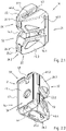
- the device 10 also referred to as a railing attachment adapter, is used for the detachable attachment of at least one railing device 11 to a scaffolding element that is vertical in its position of use, preferably to a scaffolding tube 28, in particular a scaffolding post 12.
- the main elements of the railing attachment adapter 10 include a connection head 14 provided with a railing attachment bracket 15 and a wedge 16, preferably connected thereto in a captive manner, for the detachable attachment of the railing attachment adapter 10 to at least one opening 18 ; 18.1, 18.2 for pushing through the wedge 16 having projection 17, here designed as a perforated disk 17, of the scaffolding element 12.
- the railing attachment bracket 15 is permanently connected to the connection head 14 by welding.
- a locking lever 20 that can be pivoted about a pivot axis 19 is articulated on the railing attachment bracket 15 .
- connection head 14 in the Figures 3.1, 3.2 and 4.1 to 4.6 is shown as a separate component, i.e. in a phase of manufacture of the railing connection adapter, before the connection head 14 and the railing attachment bracket 15 are permanently connected to one another by welding, and which is also shown in FIGS Figures 1.1, 1.2 , 5-7 , 8.1 and 9 each shown as a component of the railing attachment adapter 10 is described in more detail below. It is partly assumed that the connection head 28 is in a position of use or installation position, as is shown in particular in FIGS Figures 1.1, 1.2 , 9.1 and 9 is shown:
- the connection head 28 consists of metal, preferably malleable cast iron, cast steel or steel.
- the connection head 14 is preferably galvanized.
- connection head 14 has a connection part 21 and a system part 22, which are connected to one another in one piece.
- the contact part 22 of the connection head 14 of the railing attachment adapter 10 has on its contact side 23, in the usage position of the connection head 14, vertical contact wall parts 24.1, 24.2, the vertical contact surfaces 25.1, 25.2 for contact with scaffolding element outer surfaces 13 of a scaffolding element, in particular a scaffold post 12 has.
- the connection head 14 has a first head part 26.1, which is upper in its position of use, and a second head part 26.2, which is lower in its position of use.
- the first head part 26.1 has a first wedge opening 27.1 of the wedge openings 27.1, 27.2, which is upper in the position of use, for the wedge 16 which can be inserted or has been inserted through the first wedge opening 27.1.
- the first head part 26.1 has a first contact surface 25.1 of the contact surfaces 25.1, 25.2 of the contact part 22, which is upper in its position of use, for contact with a first outer surface of the framework element 12.
- the second head part 26.2 has a second wedge opening 27.2 of the wedge openings 27.1, 27.2, which is lower in the position of use, for the wedge 16 which can be inserted or has been inserted through the second wedge opening 27.2. Furthermore, the second head part 26.2 has a second contact surface 25.2 of the contact surfaces 25.1, 25.2 of the contact part 22, which is lower in the position of use, for contact with a second outer surface of the framework element 12.
- the scaffolding tube of the scaffolding post 12 has an equally large outer diameter, at least in the area of the respective perforated disk 17 on both sides thereof, or in the position of use above and below it, so that the scaffolding post 12 has a circular-cylindrical outer surface 13 at least in these areas.
- connection head 14 has the first wedge opening 27.1 contained first, upper wall portion 37.1 limits. Furthermore, the connection head 14, viewed in an opposite second direction 32, ie in its position of use downwards, is provided with a second wedge opening 27.2 containing the second wall part 37.2, which is lower in the position of use.
- connection head 14 Viewed in a third direction 33 perpendicularly to the first and second directions 31, 32, the connection head 14 is bounded at the front, towards its contact side 23, with the contact wall parts 24.1, 24.2 of the contact part 22. Viewed in an opposite, fourth direction 34 , the connection head 14 is limited to the rear, towards its connection side 38 , with a rear wall part 39 of the connection part 21 which is vertical in its position of use.
- connection head 28 is delimited in a circumferential direction with side wall parts 41.1, 41.2, 41.3, 41.4 which are vertical in its position of use.
- the first wall part 37.1, the second wall part 37.2, the contact wall parts 24.1, 24.2, the rear wall part 39 and the side wall parts 41.1, 41.2, 41.3, 41.4 are cavities, preferably usable spaces, in particular wedge receiving spaces for receiving wedge parts of the wedge 16, designed to be free.
- the connecting head 28 tapers with its vertical side wall parts 41.1, 41.2, 41.3, 41.4 viewed in the third direction 33, ie forwards, towards its contact side 23.
- the rear wall part 39 has a rear wall part surface 40 which is vertical in the fourth direction 34 , ie rearwardly pointing when the connection head 14 is in the position of use.
- connection part 14 has a collar 42 that protrudes in the fourth direction 34, ie to the rear, over the rear wall part surface 40 of the rear wall part 39 and runs around in the circumferential direction.
- this collar or collar 42 has a first opening 43 for the railing attachment bracket 15.
- the first opening 43 viewed in the third direction 33, i.e. forwards, towards the contact side 23 of the connection head 28, opens into the first wedge opening 27.1 of the first head part 26.1 of the connection head 28.
- this collar 42 has in the area of the second wall part 37.2 of the second head part 37.2 of the connection head 14 has a second opening 44. This second opening 44 is used to drain liquid zinc during or after galvanizing the connection head.
- the rear wall part 39 of the connection head 14 has a central, preferably circular,
- This central passage opening 45 is also used to drain the liquid zinc during or after the galvanizing of the connection head 14.
- the first head part 26.1 which is upper in the position of use of the connection head 14, is bounded by the side wall parts 41.1 and 41.2.
- the side wall part 41.1 has the side wall outer surfaces 46.1 which are vertical in the position of use.
- the side wall part 41.2 has the vertical side wall outer surfaces 46.2 in the position of use.
- the side wall outer surfaces 46.1 and 46.2 run in the third direction 33, ie forwards, towards the contact side 23, in a wedge-like manner towards an imaginary central axis 47 and enclose a wedge angle 48.
- the second lower in the position of use of the connection head 14,
- Head part 26.2 is bounded by side wall parts 41.3 and 41.4.
- the side wall part 41.3 has the side wall outer surfaces 46.3 which are vertical in the position of use.
- the side wall part 41.4 has the side wall outer surfaces 46.4 which are vertical in the position of use.
- the side wall outer surfaces 46.3 and 46.4 run in the third direction 33, ie forwards, towards the contact side 23, in a wedge-like manner towards the imaginary central axis 47 and enclose the wedge angle 48.
- wedge angle 48 is an acute angle.
- the wedge angle 48 here is about 44 degrees or about 45 degrees.
- the side wall part outer surfaces 46.1 and 46.3 of the side wall parts 41.1 and 41.3 on the one hand, and the side wall part outer surfaces 41.2 and 41.4 of the side wall parts 41.2 and 41.4 on the other hand, extend on both sides of a connection head center plane of symmetry 50 containing the central axis 47 of the connection head 14, which is designed symmetrically thereto.
- the central plane of symmetry of the connection head 50 has, viewed in a projection in a plane perpendicular to the central plane of symmetry 50 of the connection head, an angle 51.1, 51.2 of the same size to the side wall part outer surfaces 46.1, 46.2, 46.3, 46.4 of the side wall parts 41.1, 41.2, 41.3, 41.4 on.
- This angle 51.1, 51.2 is half as large as the wedge angle 48.
- first head part 26.1 which is upper in the position of use
- second head part 26.2 which is lower in the position of use
- head part that reaches as far as the connection part 21 and in the third direction 33, i.e. forwards, to the contact side 23 and to the outer surfaces of the side wall part 46.1, 46..2, 46.3, 46.4 of the side wall parts 41.1, 41.2, 41.3, 41.4 open, in the position of use horizontal, slot 52 for, preferably horizontal, plugging the connection head 48 on one of the perforated discs 17 is formed.
- first direction 31 i.e.
- the slip-on slot 52 is delimited towards the first head part 26.1 with first slot surfaces 53.1, 53.2 of the first head part 26.1, which is upper in the position of use and is, in the viewed in the second direction 32, i.e. downwards, towards the second, lower head part 26.2, with second slot surfaces 54.1, 54.2 of the second head part 26.2, which are lower in the position of use and border on both sides of a slot which is horizontal when the connection head 14 is in the position of use - Central plane 55 of the slot 52 extend.
- the center plane 55 of the attachment slot extends perpendicularly to the center axis 47.
- the center plane 55 of the attachment slot and the center plane of symmetry 50 of the connection head are formed perpendicular to one another.
- a passage 56 for the wedge 16 is formed between the first wedge opening 27.1 and the second wedge opening 27.2, which passage extends through the first head part 26.1 and through the second head part 26.2, crossing the slip-on slot 52.
- connection head 14 can be positively locked with the projection 17 and braced with the framework element 12 with the aid of the wedge 16 that can be inserted or inserted through the at least one opening 18 of the projection 17 of the framework element 12 to form a detachable connection (see Fig Figures 5-7 , 8.1 and 9 ).
- the wedge 16 which can also be called the connection wedge, is also made of metal.
- the wedge 16 is preferably galvanized.
- the wedge 16 has a first wedge end 57.1, which is upper in the position of use of the connection head 28, and a second wedge end 57.2, which is lower in the position of use of the connection head 14.
- the wedge 16 tapers in the manner of a wedge from its first wedge end 57.1 to its second wedge end 57.2.
- the wedge 16 is captively connected to the connection head.
- the wedge 16 has a thickening 58, for example a rivet head, at its second wedge end 57.2.
- the width of the thickening is greater than the width of the first wedge opening 27.1 designed as a rectangular wedge receiving slot.
- the rear wall part 39 of the connection head 14 is rectangular in shape.
- the rear wall part surface 40 of the rear wall part 39 has a rectangular outer contour 59 .
- the connection part 21 of the connection head 14 has, in a fifth direction 35, viewed perpendicularly to the attachment slot center plane 55, a connection part height 60 and, viewed in a sixth direction 36 perpendicular thereto, a connection part width 61 which is smaller than the connection part height 60.
- the rear wall part surface 40 extends perpendicularly to the attachment slot center plane 55 and extends perpendicularly to the connection head-connection head center plane of symmetry 50.
- the rear wall part surface 40 is preferably flat.
- a railing fastening device 62 for the detachable fastening of the at least one railing device 11 is permanently fastened by welding to the connection part 21 of the connection head 14 of the railing fastening adapter 10 .
- the railing fastening device 62 comprises the railing fastening bracket 15 and a locking lever 20.
- the locking lever 20 is pivoted relative to the railing fastening bracket 15 about a pivot axis 19 on the railing fastening bracket 15.
- the railing attachment bracket 15 is a rigid component Metal.
- the railing attachment bracket 15 is preferably galvanized. Consequently, the structural unit formed from the connection head 14 and the railing attachment bracket 15 is made of metal, preferably made of galvanized metal.
- the railing attachment bracket 15 as a separate component in the Figures 4.1 and 4.2 is shown, ie in a phase of manufacture of the railing connection adapter 10 before the connection head 14 and the railing attachment bracket 15 are permanently connected to each other by welding, and also in the Figures 1.1, 1.2 , 5-7 , 8.1 and 9 each shown as a component of the railing attachment adapter 10 is described in more detail below:
- the railing attachment bracket 15 has a rectangular through hole 63 for releasably inserting at least one railing rod end of at least one railing rod 11 of the at least one railing device and for receiving a railing rod support part of the at least one railing rod end.
- the through-hole 63 is delimited by wall parts 71, 72, 73, 74 of the railing fastening bracket 15 and is enclosed without a gap or without any interruptions.
- the through hole 63 has a through hole width 66 and a through hole length or height 70 .
- the through-hole length or height is much greater than the through-hole width 66.
- the through-hole length or height is at least twice or at least three times the through-hole width 66.
- the through-hole Length or height 55 mm.
- the through-hole width is preferably 16 mm.
- the slot width 77 is 16 mm, for example.
- the slot height 78 is 55 mm, for example.
- the rectangular through-hole 63 extends along its longitudinal axis 64.
- the longitudinal axis 64 of the through-hole 63 extends perpendicularly to the attachment slot center plane 55 of the connection head 14 and extends parallel to the center axis 47.
- the railing fastening strap 15 consists of a flat material 65 and has a uniform strap thickness 67 .
- the railing attachment bracket 15 has a flat, first side surface 68.1 and a flat, second side surface 68.2 pointing in the opposite direction, which extends parallel to the first side surface 68.1.
- the through hole 63 extends continuously between the first side surface 68.1 and the second side surface 68.2.
- the side surfaces 68.1 and 68.2 extend on both sides of an imaginary tab center plane 69 of the railing attachment tab 15.
- Both the longitudinal axis 64 of the through hole 63 and the tab center plane 69 of the railing attachment tab 15 lie in an imaginary plane which the central axis 47 contains. In the exemplary embodiment, this plane extends parallel to the connection head center plane of symmetry 50 .
- the tab center plane 69 therefore coincides with the connection head center plane of symmetry 50 .
- the longitudinal axis 64 of the through hole 63 of the railing attachment bracket 15 lies in the connection head center plane of symmetry 50
- the railing fastening bracket 15 has a support part 71, a lift-off securing part 72, a first railing support part 73 and a second railing support part 74, which delimit and enclose the rectangular through-hole 63.
- the center axis can be the post axis 47 of the scaffolding post 12.
- the support part 71 has a support surface 75, which is horizontal in the position of use, for vertically supporting at least one end of the railing rod of at least one railing rod 11 of the at least one railing device in the second direction 32, i.e. downwards in the position of use.
- the bearing surface 75 faces in the first direction 31 viewed, i.e. upwards in the position of use, from the first, in the position of use upper, slot surfaces 53.1, 53.2 of the first, in the position of use upper, head part 26.1 of the connection head 14 at a distance 76 of approximately 21 mm. Since the projection or the perforated disk 17 has a thickness of about 9 mm, the bearing surface 75, viewed in the first direction 31, i.e.
- the anti-lifting device part 72 has a horizontal anti-lifting surface 79 pointing in the second direction 32, i.e. downwards in the position of use, for preventing vertical lifting of the at least one end of the baluster of the at least one handrail 11 in the first direction 31, i.e. in the position of use of the connection head or .
- the railing attachment bracket 15 or its second railing support part 74 is permanently connected to the rear wall part 39 of the connection head 14, specifically to its rear wall part surface 40, by welding.
- the anti-lifting part 72 of the railing attachment bracket 15 has a through-opening 80 for Fastening means, preferably in the form of a bolt or grooved pin 87 on.
- the fastening means 87 forms or comprises the pivot axis 19 for the locking lever 20 which can be pivoted about it.
- the pivot axis 19 extends perpendicularly to the central axis 47 and also perpendicularly to the first direction 31 or perpendicularly to the longitudinal axis 64 of the through hole 63 or perpendicularly to the tab center plane 69.
- the railing attachment bracket 15 extends in the first direction 31, ie upwards in the position of use, beyond the first head part 26.1, so that the through hole 63 extends at least partially over the first head part 26.1 extends beyond.
- the through-hole 63 viewed in the first direction 31, extends over more than two-thirds of its through-hole height or through-hole length 70 beyond the first head part 26.1.
- the locking lever 20 which can be pivoted manually about the pivot axis 19 relative to the railing attachment bracket 25 or relative to the connection head 28, is attached to the anti-lifting part 72 of the railing attachment bracket 15, preferably captively.
- the locking lever is in the Figures 1.1, 1.2 , 5-7 , 8.1 and 9 shown.
- the locking lever 20 is preferably made of plastic.
- the locking lever 20 has, at a vertical distance from the pivot axis 19 in the position of use, a locking surface 82 for locking the at least one railing device 11 in a form-fitting manner and free of clamping force against a vertical, in the position of use of the connection head 14 or the railing attachment bracket 15 Removal of the railing device 11 in the first direction 31, ie in the position of use upwards, in a locking position 83 of the locking lever 20.
- the locking lever 20 is attached to the anti-lifting part 72 of the railing attachment bracket 15 with the aid of the attachment means containing the pivot axis 19 .
- the locking lever 20 can be pivoted about the pivot axis 19 from an unlocking position into the locking position 83 shown in the figures, and vice versa.
- the locking position 83 of the locking lever 20 In the locking position 83 of the locking lever 20, its locking surface 82 is opposite the bearing surface 75 of the bearing part 71 and, as viewed in the first direction 31, i.e. upwards in the position of use, in a vertical position in which the railing attachment bracket 15 is in the position of use Distance 84 to the bearing surface 75 of the bearing part 71, ie in the position of use above the bearing surface 75 of the bearing part 71, is arranged.
- the pivot axis 19 is in the locking position 83 of the locking lever 20, viewed in the first direction 31, i.e. in the usage position of the connection head 14 or the railing attachment bracket 15 upwards, in a distance 85 to or above the locking surface 82 of the locking lever 20, which is vertical in the position of use.
- the railing attachment bracket 15 extends in the first direction 31, i.e. upwards in the position of use, through the first opening 43 in the fourth direction 34, i.e. backwards, over the rear wall part surface 40 of the rear wall part 39 of the connection head 14 protruding waistband or collar 42 through.
- the first opening 43 has an opening width 86 which is only slightly larger than the here uniform strap thickness 67 of the railing fastening strap 15 consisting of the flat material 65.
- each of a scaffold post 12 and a railing attachment adapter 10 are shown.
- a plurality of perforated discs 17 are attached to each scaffold post 12 by welding at regular longitudinal intervals, preferably at a grid spacing of 50 centimeters.
- Each perforated disk 17 has several, eight here, openings 18; 18.1, 18.2 to push through the wedge 16.
- connection head 14 of the railing attachment adapter 10 is placed horizontally with its slot 52 on the assigned perforated disk 17 and the wedge 16 is pushed through the first head part 26.1 and through the selected small opening 18.1 of the assigned perforated disk 17 as well as through the second head part 26.2 of the connection head 14, so that a detachable connection is established, in which the connection head 14 of the railing fastening adapter 10 is positively locked with the associated perforated disk 17 with the aid of the wedge 16 and via the circular-cylindrical outer surface of the associated Scaffolding post 12 abutting contact surfaces 25.1, 25.2 of the system wall parts 24.1, 24.2 of the connection head 14 are braced with the scaffolding post 12.
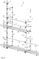
- a scaffolding 91 which is a modular scaffolding.
- the scaffolding 91 consists of several scaffolding posts 12; 12.1, 12.2 constructed, each having a plurality of perforated disks 17.
- On the perforated discs 17 are, inter alia, longitudinal bars 96 and crossbars 97 on their Attached connection heads by means of a wedge per connection head 28.
- first, lower floor 93.1 and in a second, next higher floor scaffolding floors 95 are hung on crossbars 97 .
- the scaffolding 91 is constructed on the first floor 93.1 with railing devices in the form of longitudinal bars 96.
- Railing fastening devices 10 are releasably fastened to perforated disks 17 of the scaffolding posts 12.1 of the second floor 93.2 by means of their wedges 16.
- the scaffolding 91 is set up with railing devices 11 that are or can be mounted in advance.
- These railings are straight railing rods 11; 11.1, 11.2. These each have a hanging hook 94 for hanging on or in a railing attachment bracket 15 of the railing attachment adapter 10 on their two railing rod ends pointing away from one another in opposite directions.
- the railing rods 11; 11.1, 11.2 can be hung or hung on railing attachment brackets 15 of the railing attachment adapter 10.
- FIG 5 a first assembly phase is shown, in which a first railing rod 11.1, which is suspended in the area of a first end of its two railing rod ends using the suspension hook 94 provided there on a first railing attachment bracket 15 of a first railing attachment adapter 10, the is releasably attached to the uppermost perforated disk 17 of the first scaffolding post 12.1 shown in the front right by means of its wedge 16.
- This first scaffolding post 12.1 includes four perforated discs 17.
- the first scaffolding post 12.1 is attached to a second scaffolding post 12.2.
- the second frame post 12.2 comprises only two perforated discs 17.
- the second frame post 12.2 has an effective length which is half the effective length of the first frame post 12.1.
- a fitter 92 still standing on the floor or from the first floor 93.1, can still counter in a Falling secured position, also a second railing rod 11.2 on a second railing attachment bracket 15 of a second railing attachment adapter 10, which is mounted on the next perforated disc 17 of the same scaffolding post 12.1, in the same or similar way and Hang in the same way as described above.
- This second railing rod 11.2 has the same effective length as the first railing rod 11.1.
- the fitter 92 still standing on the ground or from the first floor 93.1, in a position still secured against falling, can take a third scaffolding post 12.3, which has the same effective length as the first post 12.1 and, preferably four, perforated discs 17 includes.
- the fitter 92 can then fasten the first railing rod 11.1 and also the second railing rod 11.2 to the desired railing fastening bracket 15 of the respectively assigned railing fastening adapter 10, which with its respective connection head 14 is attached to the assigned perforated disk 17 of the third scaffolding standard 12.3 was attached and fixed there by means of the respective wedge 16. In this way a second assembly phase can be achieved, which in figure 6 is shown.
- the assembler 92 still standing on the ground or from the first floor, in a position still secured against falling, can grip the third scaffolding post 12.3 with his hands, together with the railing rods 11.1 also attached to the first scaffolding post 12.1 , 11.2, i.e. together with the first baluster 11.1 and the second baluster 11.2, in the next higher, here second floor 93.2 upwards, after which he can attach the third scaffolding post 12.3 to a fourth scaffolding post 12.4 already mounted on the first floor 93.1.
- This fourth frame post 12.4 has the same effective length as the second frame post 12.2.
- a third assembly phase is reached, in which the first railing rod 11.1 forming a hip or back railing and the second railing rod 11.2 are fastened in advance, forming a knee railing, on the second floor 93.2 (see figure 7 ).
- the fitter 92 can then climb onto the scaffolding floors 95 of the second floor 93.2 and is then secured there against falling over the two banister rods 11.1, 11.2 that have already been mounted in advance.
Landscapes
- Engineering & Computer Science (AREA)
- Architecture (AREA)
- Mechanical Engineering (AREA)
- Civil Engineering (AREA)
- Structural Engineering (AREA)
- Bridges Or Land Bridges (AREA)
Claims (15)
- Dispositif (10) pour la fixation amovible d'au moins un équipement de garde-corps (11) à un élément d'échafaudage (12), comprenant une tête de raccordement (14) et un coin (16) pour la fixation amovible du dispositif (10) à une saillie (17) de l'élément d'échafaudage (12) comportant au moins un percement (18) pour faire passer le coin (16) à travers,sachant que la tête de raccordement (14) peut être verrouillée par conformité de forme pour former une liaison amovible avec la saillie (17) à l'aide du coin (16) emboîtable à travers au moins un percement (18) de la saillie (17) et peut être serrée à l'élément d'échafaudage (12),et sachant que la tête de raccordement (14) comporte une pièce de raccordement (21) et une pièce de d'appui (22), qui sont reliées l'une à l'autre en une seule pièce,et sachant que la pièce d'appui (22) comporte des pièces de paroi d'appui (24.1, 24.2), qui comportent des surfaces d'appui (25.1, 25.2) pour la dépose sur des surfaces extérieures d'élément d'échafaudage (13) de l'élément d'échafaudage (12),et sachant que la tête de raccordement (14) comporte une première pièce de tête (26.1) et une deuxième pièce de tête (26.2), qui comportent les ouvertures de coin (27.1, 27.2) pour le coin (16) emboîté ou pouvant être emboîté à travers celles-ci et sont reliées l'une à l'autre en une seule pièce,et sachant que la première pièce de tête (26.1) comporte une première ouverture de coin (27.1) des ouvertures de coin (27.1, 27.2) pour le coin (16) emboîté ou pouvant être emboîté à travers la première ouverture de coin (27.1) et comporte une première surface d'appui (25.1) des surfaces d'appui (25.1, 25.2) de la pièce d'appui (22) pour la dépose sur une première surface extérieure d'élément d'échafaudage des surfaces extérieures d'élément d'échafaudage (13) de l'élément d'échafaudage (12),et sachant que la deuxième pièce de tête (26.2) comporte une deuxième ouverture de coin (27.2) des ouvertures de coin (27.1, 27.2) pour le coin (16) emboîté ou pouvant être emboîté à travers la deuxième ouverture de coin (27.2) et comporte une deuxième surface d'appui (25.2) des surfaces d'appui (25.1, 25.2) de la pièce d'appui (22) pour la dépose sur une deuxième surface extérieure d'élément d'échafaudage des surfaces extérieures d'élément d'échafaudage (13) de l'élément d'échafaudage (12),et sachant que la tête de raccordement (14), considérée dans une première direction (31), est limitée par une première pièce de paroi (37.1) contenant la première ouverture de coin (27.1) et considérée dans une deuxième direction opposée (32), est limitée par une deuxième pièce de paroi (37.2) contenant la deuxième ouverture de coin (27.2),et sachant que la tête de raccordement (14), considérée dans une troisième direction (33), par rapport à sa face d'appui (23), est limitée par les pièces de paroi d'appui (24.1, 24.2) de la pièce d'appui (22) et considérée dans une quatrième direction opposée (34), par rapport à ses faces de raccordement (38), est limitée par une pièce de paroi arrière (39) de la pièce de raccordement (21),et sachant que la tête de raccordement (14) est limitée dans une direction périphérique par des pièces de paroi latérales (41.1, 41.2, 41.3, 41.4),et sachant que la première pièce de paroi (37.1), la deuxième pièce de paroi (37.2), les pièces de paroi d'appui (24.1, 24.2), la pièce de paroi arrière (39) et les pièces de paroi latérales (41.1, 41.2, 41.3, 41.4) sont constituées en laissant libre des espaces creux,et sachant que la tête de raccordement (14), considérée dans la troisième direction (33), se réduit vers sa face d'appui (23) avec ses pièces de paroi latérales (41.1, 41.2, 41.3, 41.4),et sachant que les pièces de paroi latérales (41.1, 41.2, 41.3, 41.4) comportent des surfaces extérieurs de pièce de paroi latérale (46.1, 46.2, 46.3, 46.4), qui, considérées dans la troisième direction (33), convergent en forme de coin sur un axe central (47) et forment un angle de coin (48),et sachant que la pièce de paroi arrière (39) comporte une surface de pièce de paroi arrière (40) tournée dans la quatrième direction (34),et sachant qu'entre la première pièce de tête (26.1) et la deuxième pièce de tête (26.2) est constituée une fente d'emboîtement (52) allant jusqu'à la pièce de raccordement (21), considérée dans la troisième direction (33), ouverte vers la face d'appui (23) et vers les surfaces extérieures de pièce de paroi latérale (46.1, 46.2, 46.3, 46.4) des pièces de paroi latérale (41.1, 41.2, 41.3, 41.4), pour l'emboîtement de la tête de raccordement (28) sur la saillie (17),et sachant que la fente d'emboîtement (52), considérée dans la première direction (31), est limitée par rapport à la première pièce de tête (26.1) par des premières surfaces de fente (53.1, 53.2) de la première pièce de tête (26.1) et considérée dans la deuxième direction (32), est limitée par rapport à la deuxième pièce de tête (26.2) par les deuxièmes surfaces de fente (54.1, 54.2) de la deuxième pièce de tête (26.2), qui s'étendent des deux côtés d'un plan médian de fente d'emboîtement (55) de la fente d'emboîtement (52),et sachant qu'entre la première ouverture de coin (27.1) et la deuxième ouverture de coin (27.2) est constitué un passage (56) pour le coin (16), qui s'étend à travers la première pièce de tête (26.1) et à travers la deuxième pièce de tête (26.2) en croisant la fente d'emboîtement (52),et sachant qu'à la pièce de raccordement (21) de la tête de raccordement (14) est fixé en permanence un dispositif de fixation de garde-corps (62) pour la fixation amovible d'au moins un équipement de garde-corps (11),sachant que le dispositif de fixation de garde-corps (62) contient une attache de fixation de garde-corps (15) rigide, qui est reliée en permanence à la pièce de paroi arrière (39) de la tête de raccordement (14) etcaractérisé en ce que la tête de raccordement comporte un trou de passage (63) de forme rectangulaire ou structuré comme un trou oblong pour l'emboîtement amovible d'au moins une extrémité de barre de garde-corps d'au moins une barre de garde-corps d'au moins un équipement de garde-corps (11) et pour loger une pièce d'appui de barre de garde-corps d'au moins une extrémité de barre de garde-corps et en ce que le trou de passage (63) s'étend le long de son axe longitudinal (64), qui s'étend perpendiculairement au plan médian de fente d'emboîtement (55) et/ou qui s'étend soit en direction de l'axe central (47), soit parallèlement à l'axe central (47).
- Dispositif selon la revendication 1, caractérisé en ce que l'épaisseur d'attache de fixation de garde-corps (15) comportant une épaisseur d'attache uniforme (67) est composée d'un matériau plat (65).
- Dispositif selon la revendication 1 ou 2, caractérisé en ce que l'attache de fixation de garde-corps (15) comporte une première surface latérale (68.1) et une deuxième surface latérale (68.2) s'éloignant dans le sens opposé de celle-ci entre lesquelles s'étend le trou de passage (63) et qui s'étendent des deux côtés d'un plan médian d'attache (69) de l'attache de fixation de garde-corps (15).
- Dispositif selon l'une quelconque des revendications précédentes, caractérisé en ce que les surfaces extérieures de pièce de paroi latérale (46.1, 46.2, 46.3, 46.4) s'étendent des deux côtés d'un plan médian de tête de raccordement (50) contenant l'axe central (47), qui, considéré dans une projection dans un plan constitué perpendiculairement au plan médian de tête de raccordement (50), comporte un angle (51.1, 51.2) de même grandeur par rapport aux surfaces extérieures de pièce de paroi latérale (46.1, 46.2, 46.3, 46.4) des pièces de parois latérales (41.1, 41.2, 41.3, 41.4), qui est à moitié aussi grand que l'angle de coin (48) et en ce que le plan médian d'attache (69) coïncide avec le plan médian de tête de raccordement (50)
ou
en ce que les surfaces extérieures de pièce de paroi latérale (46.1, 46.2, 46.3, 46.4) s'étendent des deux côtés d'un plan de symétrie médian de tête de raccordement (50) contenant l'axe central (47) de la tête de raccordement (28) structurée symétriquement à celui-ci, qui, considéré dans une projection dans un plan constitué perpendiculairement au plan de symétrie médian de tête de raccordement (50), comporte un angle (51.1, 51.2) de même grandeur par rapport aux surfaces extérieures de pièce de paroi latérale (46.1, 46.2, 46.3, 46.4) des pièces de paroi latérale (41.1, 41.2, 41.3, 41.4), qui est à moitié aussi grand que l'angle de coin (48) et en ce que le plan médian d'attache (69) coïncide avec le plan de symétrie médian de tête de raccordement (50). - Dispositif selon l'une quelconque des revendications précédentes, caractérisé en ce que l'axe longitudinal (64) ou le plan médian d'attache (69) est disposé soit dans un plan qui est disposé parallèlement au plan médian de tête de raccordement à une distance du plan médian de tête de raccordement, soit coïncide avec le plan médian de tête de raccordement (50) ou avec le plan de symétrie médian de tête de raccordement (50).
- Dispositif selon l'une quelconque des revendications précédentes, caractérisé en ce que l'attache de fixation de garde-corps (15) est fixée en permanence à la surface de pièce de paroi arrière (40) de la pièce de paroi arrière (39) de la tête de raccordement (14), qui est constituée perpendiculairement au plan médian de fente d'emboîtement (55).
- Dispositif selon l'une quelconque des revendications précédentes, caractérisé en ce que l'attache de fixation de garde-corps (15) s'étend dans la première direction (31) au-delà de la première pièce de tête (26.1) de telle manière que le trou de passage (63) s'étend au moins en pièce au-delà de la première pièce de tête (26.1).
- Dispositif selon l'une quelconque des revendications précédentes, caractérisé en ce que la pièce de raccordement (21), comporte, au moins dans une première zone de bordure attribuée à la première pièce de tête (26.1), considérée dans la quatrième direction (34), un collet (42) ou col faisant saillie sur la surface de pièce de paroi arrière (40) de la paroi arrière (39), qui est doté d'un premier percement (43) à travers lequel s'étend une pièce de paroi (74) de l'attache de fixation de garde-corps (15) dans la première direction (31), sachant que le percement (43) comporte une largeur de percement (86) qui est faiblement plus grande qu'une épaisseur d'attache (67) de l'attache de fixation de garde-corps (15) dans la zone du premier percement (43).
- Dispositif selon la revendication 8, caractérisé en ce que le premier percement (43), considéré dans la troisième direction (33), par rapport à la face d'appui (23) de la tête de raccordement (14), débouche dans la première ouverture de coin (27.1).
- Dispositif selon l'une quelconque des revendications précédentes, caractérisé en ce que la pièce de paroi arrière (39) de la tête de raccordement (14) est constituée de forme rectangulaire et/ou en ce que la surface de la paroi de paroi arrière (40) de la pièce de paroi arrière (39) comporte un profil extérieur (59) de forme rectangulaire et en ce que la pièce d'appui (22) de la tête de raccordement (14), considérée dans une cinquième direction (35), perpendiculairement au plan médian de la fente d'emboîtement (55), comporte une hauteur de pièce d'appui (60) et considérée dans une sixième direction (36) perpendiculairement à celui-ci, comporte une largeur de pièce d'appui (61), qui est plus petite que la hauteur de pièce d'appui (60).
- Dispositif selon l'une quelconque des revendications précédentes, caractérisé en ce que l'attache de fixation de garde-corps (15) comprend une pièce d'appui (71), une pièce anti-relevage (72), une première pièce d'appui de garde-corps (73) et une deuxième pièce d'appui de garde-corps (74), qui limitent le trou de passage (63), sachant que la pièce d'appui (71) comporte une surface d'appui (75) pour appuyer au moins une extrémité de barre de garde-corps d'au moins une barre de garde-corps d'au moins un équipement de garde-corps (11) dans la deuxième direction (32) et sachant que la deuxième pièce d'appui de garde-corps (74) est reliée en permanence à la pièce de paroi arrière (39) de la tête de raccordement et sachant que la pièce anti-relevage (72) comporte une surface anti-relevage (79) dirigée dans la deuxième direction (32) pour éviter un relevage d'au moins un équipement de garde-corps (11) dans la première direction (31).
- Dispositif selon la revendication 11, caractérisé en ce que la surface d'appui (75), considérée dans la première direction (31), comporte une distance (78) soit du plan médian de fente d'emboîtement (55), entre 23 mm et 63 mm, ou de 43 mm ou de 26 mm, soit comporte une distance (76) des premières surfaces de fente (53.1, 53.2) de la première pièce de tête (26.1), entre 18 mm et 58 mm ou de 38 mm ou 21 mm.
- Dispositif selon l'une quelconque des revendications précédentes, caractérisé en ce qu'un levier de verrouillage (20) est fixé pouvant pivoter sur l'attache de fixation de garde-corps (15) autour d'un axe de pivotement (19) par rapport à la tête de raccordement (14), qui comporte une surface de verrouillage (82) pour le verrouillage par conformité de forme d'au moins un équipement de garde-corps (11) contre tout enlèvement de celui-ci dans la première direction (31) dans une position de verrouillage (83) du levier de verrouillage (20) et qui est fixé à l'attache de fixation de garde-corps (15) à l'aide d'un moyen de fixation (87) contenant l'axe de pivotement (19) et peut pivoter autour de l'axe de pivotement (19) d'une position de déverrouillage à la position de verrouillage (83) et vice versa et sachant que la surface de verrouillage (82) du levier de verrouillage (20) dans la position de verrouillage (83) du levier de verrouillage (20) de la surface d'appui (75) de la pièce d'appui (71) se situe en face de l'attache de fixation de garde-corps (15) et, considérée dans la première direction (31) est disposée à une distance (84) par rapport à la surface d'appui (75) de la pièce d'appui (71), et sachant que l'axe de pivotement (19) est disposé dans la position de verrouillage (83) du levier de verrouillage (20), considérée dans la première direction (31), à une distance (85) par rapport à la surface de verrouillage (82) du levier de verrouillage (20) .
- Agencement (90) d'un élément d'échafaudage (12) et d'un dispositif (10) selon l'une quelconque des revendications précédentes, caractérisé en ce que l'élément d'échafaudage (12) est relié en permanence à la saillie (17), qui comporte au moins un percement (18) et sachant que la tête de raccordement (14) du dispositif (10) est emboîtée avec sa fente d'emboîtement (52) sur la saillie (17) et le coin (16) est emboîté à travers la première pièce de tête (26.1), à travers le percement (18) et à travers la deuxième pièce de tête (26.2) de telle manière qu'une liaison amovible est réalisée par laquelle la tête de raccordement (14) du dispositif (10) est verrouillée par conformité de forme avec la saillie (17) à l'aide du coin (16) et est serrée à l'élément d'échafaudage (12) par le biais des surfaces d'appui (25.1, 25.2) des pièces de paroi d'appui (24.1, 24.2) s'appliquant aux surfaces extérieures d'élément d'échafaudage (13) de l'élément d'échafaudage (12).
- Echafaudage (91) avec au moins un agencement (90) selon la revendication 14, qui peut être construit avec un équipement de garde-corps en avance (11) ou est construit avec un équipement de garde-corps (11) en avance, caractérisé en ce qu'au moins une extrémité de barre de garde-corps d'au moins une barre de garde-corps d'au moins un équipement de garde-corps (11) est emboîtée dans le trou de passage (63) de forme rectangulaire ou constituée comme trou oblong de l'attache de fixation de garde-corps (15) du dispositif (10) et y est appuyée et/ou suspendue dans la deuxième direction (32) à l'attache de fixation de garde-corps (15) .
Applications Claiming Priority (2)
| Application Number | Priority Date | Filing Date | Title |
|---|---|---|---|
| DE102019133939.1A DE102019133939A1 (de) | 2019-12-11 | 2019-12-11 | Vorrichtung zum lösbaren befestigen wenigstens einer geländereinrichtung an einem gerüstelement |
| PCT/DE2020/100879 WO2021115519A1 (fr) | 2019-12-11 | 2020-10-09 | Dispositif de fixation amovible d'au moins un système garde-corps à un élément d'échafaudage |
Publications (2)
| Publication Number | Publication Date |
|---|---|
| EP4010545A1 EP4010545A1 (fr) | 2022-06-15 |
| EP4010545B1 true EP4010545B1 (fr) | 2023-01-25 |
Family
ID=73039754
Family Applications (1)
| Application Number | Title | Priority Date | Filing Date |
|---|---|---|---|
| EP20799982.2A Active EP4010545B1 (fr) | 2019-12-11 | 2020-10-09 | Dispositif de fixation amovible d'au moins un système garde-corps à un élément d'échafaudage |
Country Status (3)
| Country | Link |
|---|---|
| EP (1) | EP4010545B1 (fr) |
| DE (2) | DE102019133939A1 (fr) |
| WO (1) | WO2021115519A1 (fr) |
Citations (2)
| Publication number | Priority date | Publication date | Assignee | Title |
|---|---|---|---|---|
| EP0276487B1 (fr) * | 1987-01-24 | 1991-03-13 | Langer geb. Layher, Ruth | Echaufaudage avec moyens de raccord |
| DE19504038C2 (de) * | 1995-02-08 | 2000-05-11 | Layher W Vermogensverw Gmbh | Gerüst |
Family Cites Families (9)
| Publication number | Priority date | Publication date | Assignee | Title |
|---|---|---|---|---|
| DE2449124C3 (de) | 1974-10-16 | 1980-01-03 | Eberhard 7129 Gueglingen Layher | Verbindungsvorrichtung für Gerüstelemente |
| DE2822676C2 (de) | 1978-05-24 | 1982-08-19 | Eberhard 7129 Güglingen Layher | Verbindungsvorrichtung für Gerüstelemente |
| DE3934857A1 (de) | 1989-10-19 | 1991-04-25 | Langer Ruth Geb Layher | Anschlusskopf fuer geruest |
| DE19806094A1 (de) | 1998-02-14 | 1999-08-19 | Layher W Vermogensverw Gmbh | Anordnung von Tragstruktur-Elementen eines Raumtragwerkes |
| EP1911907B1 (fr) | 2006-10-11 | 2015-12-23 | Wilhelm Layher Verwaltungs-GmbH | Elément de cadre vertical en métal |
| DE102007018314A1 (de) * | 2007-04-18 | 2008-11-06 | Wilhelm Layher Verwaltungs-Gmbh | Stütze für ein Raumtragwerk sowie Verbindungsanordnung für eine Geländereinrichtung und Verfahren zum Befestigen einer Geländereinrichtung an einer Stütze |
| WO2012163340A1 (fr) | 2011-06-01 | 2012-12-06 | Wilhelm Layher Verwaltungs-Gmbh | Ensemble comprenant une pièce d'échafaudage et un élément d'échafaudage vertical |
| IT201600108828A1 (it) * | 2016-10-27 | 2018-04-27 | Amadio & C S P A | Sistema di collegamento di montanti verticali e di correnti di supporto di un piano di calpestio per un'impalcatura |
| DE102018114244A1 (de) | 2018-06-14 | 2019-12-19 | Wilhelm Layher Verwaltungs-Gmbh | Einzelner Gerüststiel |
-
2019
- 2019-12-11 DE DE102019133939.1A patent/DE102019133939A1/de not_active Withdrawn
-
2020
- 2020-10-09 WO PCT/DE2020/100879 patent/WO2021115519A1/fr not_active Ceased
- 2020-10-09 DE DE112020003955.2T patent/DE112020003955A5/de active Pending
- 2020-10-09 EP EP20799982.2A patent/EP4010545B1/fr active Active
Patent Citations (2)
| Publication number | Priority date | Publication date | Assignee | Title |
|---|---|---|---|---|
| EP0276487B1 (fr) * | 1987-01-24 | 1991-03-13 | Langer geb. Layher, Ruth | Echaufaudage avec moyens de raccord |
| DE19504038C2 (de) * | 1995-02-08 | 2000-05-11 | Layher W Vermogensverw Gmbh | Gerüst |
Also Published As
| Publication number | Publication date |
|---|---|
| EP4010545A1 (fr) | 2022-06-15 |
| DE112020003955A5 (de) | 2022-05-05 |
| DE102019133939A1 (de) | 2021-06-17 |
| WO2021115519A1 (fr) | 2021-06-17 |
Similar Documents
| Publication | Publication Date | Title |
|---|---|---|
| EP1983129B1 (fr) | Support pour un ouvrage porteur en trois dimensions et dispositif de liaison pour un dispositif de garde-fou et procédé de fixation d'un dispositif de garde-fou sur un support | |
| EP3775433B1 (fr) | Agencement de connexion | |
| EP2643533B1 (fr) | Ensemble comprenant une pièce d'échafaudage et un élément d'échafaudage vertical | |
| WO2008043339A1 (fr) | Cadre vertical en métal | |
| EP3491205B1 (fr) | Élément de fixation | |
| EP3440281A1 (fr) | Ferrure pour une plinthe d'un échafaudage | |
| EP4251824A1 (fr) | Agencement de composants d'échafaudage | |
| EP2499311B1 (fr) | Grille de protection latérale et système de protection latérale | |
| EP4538481A1 (fr) | Dispositif pour la fixation de protections contre les chutes à des échafaudages | |
| DE102021004490A1 (de) | Modulgerüst sowie Modulgerüstriegel für ein solches | |
| EP2949833B1 (fr) | Élément de fixation pour parapet destiné à la fixation amovible sur un élément de structure, élément de structure, ensemble composé d'un parapet et d'un élément de structure et procédé de fixation et de sécurisation d'un élément de fixation | |
| EP1911907B1 (fr) | Elément de cadre vertical en métal | |
| EP3325737A1 (fr) | Échafaudage pourvu d'un élément d'accouplement | |
| EP4010545B1 (fr) | Dispositif de fixation amovible d'au moins un système garde-corps à un élément d'échafaudage | |
| EP4413218B1 (fr) | Agencement d'éléments d'échafaudage et procédé d'assemblage d'un tel agencement | |
| EP4562256B1 (fr) | Agencement de composants d'échafaudage pour un échafaudage | |
| DE19527235C2 (de) | Bühnentraverse | |
| EP0331796A1 (fr) | Dispositif renforcé de suspension pour câbles | |
| EP3705660B1 (fr) | Main courante frontale, échafaudage doté d'une telle main courante frontale et procédé de fixation côté frontal d'un échafaudage | |
| DE19946929A1 (de) | Vorrichtung zur Verbindung zweier benachbarten Gerüststiele | |
| DE3139642C1 (de) | Stahlrohrgerüst mit das Geländer bildenden Längs- und Querriegeln | |
| EP4720434A1 (fr) | Barre de garde-corps pour échafaudage et procédé de montage d'un échafaudage | |
| EP4538482A1 (fr) | Dispositif pour la fixation de protections contre les chutes à des échafaudages | |
| EP4483022A1 (fr) | Élément garde-corps, échafaudage doté d'élément garde-corps de ce type et procédé de démontage d'élément garde-corps de ce type | |
| DE10245743A1 (de) | Zerlegbares Gerüst |
Legal Events
| Date | Code | Title | Description |
|---|---|---|---|
| STAA | Information on the status of an ep patent application or granted ep patent |
Free format text: STATUS: UNKNOWN |
|
| STAA | Information on the status of an ep patent application or granted ep patent |
Free format text: STATUS: THE INTERNATIONAL PUBLICATION HAS BEEN MADE |
|
| PUAI | Public reference made under article 153(3) epc to a published international application that has entered the european phase |
Free format text: ORIGINAL CODE: 0009012 |
|
| STAA | Information on the status of an ep patent application or granted ep patent |
Free format text: STATUS: REQUEST FOR EXAMINATION WAS MADE |
|
| 17P | Request for examination filed |
Effective date: 20220309 |
|
| AK | Designated contracting states |
Kind code of ref document: A1 Designated state(s): AL AT BE BG CH CY CZ DE DK EE ES FI FR GB GR HR HU IE IS IT LI LT LU LV MC MK MT NL NO PL PT RO RS SE SI SK SM TR |
|
| GRAP | Despatch of communication of intention to grant a patent |
Free format text: ORIGINAL CODE: EPIDOSNIGR1 |
|
| STAA | Information on the status of an ep patent application or granted ep patent |
Free format text: STATUS: GRANT OF PATENT IS INTENDED |
|
| INTG | Intention to grant announced |
Effective date: 20220916 |
|
| GRAS | Grant fee paid |
Free format text: ORIGINAL CODE: EPIDOSNIGR3 |
|
| GRAA | (expected) grant |
Free format text: ORIGINAL CODE: 0009210 |
|
| STAA | Information on the status of an ep patent application or granted ep patent |
Free format text: STATUS: THE PATENT HAS BEEN GRANTED |
|
| DAV | Request for validation of the european patent (deleted) | ||
| DAX | Request for extension of the european patent (deleted) | ||
| AK | Designated contracting states |
Kind code of ref document: B1 Designated state(s): AL AT BE BG CH CY CZ DE DK EE ES FI FR GB GR HR HU IE IS IT LI LT LU LV MC MK MT NL NO PL PT RO RS SE SI SK SM TR |
|
| REG | Reference to a national code |
Ref country code: GB Ref legal event code: FG4D Free format text: NOT ENGLISH |
|
| REG | Reference to a national code |
Ref country code: CH Ref legal event code: EP |
|
| REG | Reference to a national code |
Ref country code: DE Ref legal event code: R096 Ref document number: 502020002466 Country of ref document: DE |
|
| REG | Reference to a national code |
Ref country code: AT Ref legal event code: REF Ref document number: 1546008 Country of ref document: AT Kind code of ref document: T Effective date: 20230215 Ref country code: IE Ref legal event code: FG4D Free format text: LANGUAGE OF EP DOCUMENT: GERMAN |
|
| REG | Reference to a national code |
Ref country code: LT Ref legal event code: MG9D |
|
| REG | Reference to a national code |
Ref country code: NL Ref legal event code: MP Effective date: 20230125 |
|
| P01 | Opt-out of the competence of the unified patent court (upc) registered |
Effective date: 20230502 |
|
| PG25 | Lapsed in a contracting state [announced via postgrant information from national office to epo] |
Ref country code: NL Free format text: LAPSE BECAUSE OF FAILURE TO SUBMIT A TRANSLATION OF THE DESCRIPTION OR TO PAY THE FEE WITHIN THE PRESCRIBED TIME-LIMIT Effective date: 20230125 |
|
| PG25 | Lapsed in a contracting state [announced via postgrant information from national office to epo] |
Ref country code: RS Free format text: LAPSE BECAUSE OF FAILURE TO SUBMIT A TRANSLATION OF THE DESCRIPTION OR TO PAY THE FEE WITHIN THE PRESCRIBED TIME-LIMIT Effective date: 20230125 Ref country code: PT Free format text: LAPSE BECAUSE OF FAILURE TO SUBMIT A TRANSLATION OF THE DESCRIPTION OR TO PAY THE FEE WITHIN THE PRESCRIBED TIME-LIMIT Effective date: 20230525 Ref country code: NO Free format text: LAPSE BECAUSE OF FAILURE TO SUBMIT A TRANSLATION OF THE DESCRIPTION OR TO PAY THE FEE WITHIN THE PRESCRIBED TIME-LIMIT Effective date: 20230425 Ref country code: LV Free format text: LAPSE BECAUSE OF FAILURE TO SUBMIT A TRANSLATION OF THE DESCRIPTION OR TO PAY THE FEE WITHIN THE PRESCRIBED TIME-LIMIT Effective date: 20230125 Ref country code: LT Free format text: LAPSE BECAUSE OF FAILURE TO SUBMIT A TRANSLATION OF THE DESCRIPTION OR TO PAY THE FEE WITHIN THE PRESCRIBED TIME-LIMIT Effective date: 20230125 Ref country code: HR Free format text: LAPSE BECAUSE OF FAILURE TO SUBMIT A TRANSLATION OF THE DESCRIPTION OR TO PAY THE FEE WITHIN THE PRESCRIBED TIME-LIMIT Effective date: 20230125 Ref country code: ES Free format text: LAPSE BECAUSE OF FAILURE TO SUBMIT A TRANSLATION OF THE DESCRIPTION OR TO PAY THE FEE WITHIN THE PRESCRIBED TIME-LIMIT Effective date: 20230125 |
|
| PG25 | Lapsed in a contracting state [announced via postgrant information from national office to epo] |
Ref country code: SE Free format text: LAPSE BECAUSE OF FAILURE TO SUBMIT A TRANSLATION OF THE DESCRIPTION OR TO PAY THE FEE WITHIN THE PRESCRIBED TIME-LIMIT Effective date: 20230125 Ref country code: PL Free format text: LAPSE BECAUSE OF FAILURE TO SUBMIT A TRANSLATION OF THE DESCRIPTION OR TO PAY THE FEE WITHIN THE PRESCRIBED TIME-LIMIT Effective date: 20230125 Ref country code: IS Free format text: LAPSE BECAUSE OF FAILURE TO SUBMIT A TRANSLATION OF THE DESCRIPTION OR TO PAY THE FEE WITHIN THE PRESCRIBED TIME-LIMIT Effective date: 20230525 Ref country code: GR Free format text: LAPSE BECAUSE OF FAILURE TO SUBMIT A TRANSLATION OF THE DESCRIPTION OR TO PAY THE FEE WITHIN THE PRESCRIBED TIME-LIMIT Effective date: 20230426 Ref country code: FI Free format text: LAPSE BECAUSE OF FAILURE TO SUBMIT A TRANSLATION OF THE DESCRIPTION OR TO PAY THE FEE WITHIN THE PRESCRIBED TIME-LIMIT Effective date: 20230125 |
|
| REG | Reference to a national code |
Ref country code: DE Ref legal event code: R097 Ref document number: 502020002466 Country of ref document: DE |
|
| PG25 | Lapsed in a contracting state [announced via postgrant information from national office to epo] |
Ref country code: SM Free format text: LAPSE BECAUSE OF FAILURE TO SUBMIT A TRANSLATION OF THE DESCRIPTION OR TO PAY THE FEE WITHIN THE PRESCRIBED TIME-LIMIT Effective date: 20230125 Ref country code: RO Free format text: LAPSE BECAUSE OF FAILURE TO SUBMIT A TRANSLATION OF THE DESCRIPTION OR TO PAY THE FEE WITHIN THE PRESCRIBED TIME-LIMIT Effective date: 20230125 Ref country code: EE Free format text: LAPSE BECAUSE OF FAILURE TO SUBMIT A TRANSLATION OF THE DESCRIPTION OR TO PAY THE FEE WITHIN THE PRESCRIBED TIME-LIMIT Effective date: 20230125 Ref country code: DK Free format text: LAPSE BECAUSE OF FAILURE TO SUBMIT A TRANSLATION OF THE DESCRIPTION OR TO PAY THE FEE WITHIN THE PRESCRIBED TIME-LIMIT Effective date: 20230125 Ref country code: CZ Free format text: LAPSE BECAUSE OF FAILURE TO SUBMIT A TRANSLATION OF THE DESCRIPTION OR TO PAY THE FEE WITHIN THE PRESCRIBED TIME-LIMIT Effective date: 20230125 |
|
| PG25 | Lapsed in a contracting state [announced via postgrant information from national office to epo] |
Ref country code: SK Free format text: LAPSE BECAUSE OF FAILURE TO SUBMIT A TRANSLATION OF THE DESCRIPTION OR TO PAY THE FEE WITHIN THE PRESCRIBED TIME-LIMIT Effective date: 20230125 |
|
| PLBE | No opposition filed within time limit |
Free format text: ORIGINAL CODE: 0009261 |
|
| STAA | Information on the status of an ep patent application or granted ep patent |
Free format text: STATUS: NO OPPOSITION FILED WITHIN TIME LIMIT |
|
| 26N | No opposition filed |
Effective date: 20231026 |
|
| PG25 | Lapsed in a contracting state [announced via postgrant information from national office to epo] |
Ref country code: SI Free format text: LAPSE BECAUSE OF FAILURE TO SUBMIT A TRANSLATION OF THE DESCRIPTION OR TO PAY THE FEE WITHIN THE PRESCRIBED TIME-LIMIT Effective date: 20230125 |
|
| PG25 | Lapsed in a contracting state [announced via postgrant information from national office to epo] |
Ref country code: IT Free format text: LAPSE BECAUSE OF FAILURE TO SUBMIT A TRANSLATION OF THE DESCRIPTION OR TO PAY THE FEE WITHIN THE PRESCRIBED TIME-LIMIT Effective date: 20230125 Ref country code: MC Free format text: LAPSE BECAUSE OF FAILURE TO SUBMIT A TRANSLATION OF THE DESCRIPTION OR TO PAY THE FEE WITHIN THE PRESCRIBED TIME-LIMIT Effective date: 20230125 |
|
| REG | Reference to a national code |
Ref country code: CH Ref legal event code: PL |
|
| REG | Reference to a national code |
Ref country code: BE Ref legal event code: MM Effective date: 20231031 |
|
| PG25 | Lapsed in a contracting state [announced via postgrant information from national office to epo] |
Ref country code: LU Free format text: LAPSE BECAUSE OF NON-PAYMENT OF DUE FEES Effective date: 20231009 |
|
| PG25 | Lapsed in a contracting state [announced via postgrant information from national office to epo] |
Ref country code: LU Free format text: LAPSE BECAUSE OF NON-PAYMENT OF DUE FEES Effective date: 20231009 |
|
| PG25 | Lapsed in a contracting state [announced via postgrant information from national office to epo] |
Ref country code: CH Free format text: LAPSE BECAUSE OF NON-PAYMENT OF DUE FEES Effective date: 20231031 |
|
| PG25 | Lapsed in a contracting state [announced via postgrant information from national office to epo] |
Ref country code: FR Free format text: LAPSE BECAUSE OF NON-PAYMENT OF DUE FEES Effective date: 20231031 Ref country code: CH Free format text: LAPSE BECAUSE OF NON-PAYMENT OF DUE FEES Effective date: 20231031 |
|
| PG25 | Lapsed in a contracting state [announced via postgrant information from national office to epo] |
Ref country code: BE Free format text: LAPSE BECAUSE OF NON-PAYMENT OF DUE FEES Effective date: 20231031 |
|
| PG25 | Lapsed in a contracting state [announced via postgrant information from national office to epo] |
Ref country code: IE Free format text: LAPSE BECAUSE OF NON-PAYMENT OF DUE FEES Effective date: 20231009 |
|
| PG25 | Lapsed in a contracting state [announced via postgrant information from national office to epo] |
Ref country code: IE Free format text: LAPSE BECAUSE OF NON-PAYMENT OF DUE FEES Effective date: 20231009 |
|
| PG25 | Lapsed in a contracting state [announced via postgrant information from national office to epo] |
Ref country code: BG Free format text: LAPSE BECAUSE OF FAILURE TO SUBMIT A TRANSLATION OF THE DESCRIPTION OR TO PAY THE FEE WITHIN THE PRESCRIBED TIME-LIMIT Effective date: 20230125 |
|
| PG25 | Lapsed in a contracting state [announced via postgrant information from national office to epo] |
Ref country code: BG Free format text: LAPSE BECAUSE OF FAILURE TO SUBMIT A TRANSLATION OF THE DESCRIPTION OR TO PAY THE FEE WITHIN THE PRESCRIBED TIME-LIMIT Effective date: 20230125 |
|
| GBPC | Gb: european patent ceased through non-payment of renewal fee |
Effective date: 20241009 |
|
| PG25 | Lapsed in a contracting state [announced via postgrant information from national office to epo] |
Ref country code: GB Free format text: LAPSE BECAUSE OF NON-PAYMENT OF DUE FEES Effective date: 20241009 |
|
| PG25 | Lapsed in a contracting state [announced via postgrant information from national office to epo] |
Ref country code: CY Free format text: LAPSE BECAUSE OF FAILURE TO SUBMIT A TRANSLATION OF THE DESCRIPTION OR TO PAY THE FEE WITHIN THE PRESCRIBED TIME-LIMIT; INVALID AB INITIO Effective date: 20201009 |
|
| PG25 | Lapsed in a contracting state [announced via postgrant information from national office to epo] |
Ref country code: HU Free format text: LAPSE BECAUSE OF FAILURE TO SUBMIT A TRANSLATION OF THE DESCRIPTION OR TO PAY THE FEE WITHIN THE PRESCRIBED TIME-LIMIT; INVALID AB INITIO Effective date: 20201009 |
|
| PG25 | Lapsed in a contracting state [announced via postgrant information from national office to epo] |
Ref country code: TR Free format text: LAPSE BECAUSE OF FAILURE TO SUBMIT A TRANSLATION OF THE DESCRIPTION OR TO PAY THE FEE WITHIN THE PRESCRIBED TIME-LIMIT Effective date: 20230125 |
|
| REG | Reference to a national code |
Ref country code: DE Ref legal event code: R082 Ref document number: 502020002466 Country of ref document: DE Representative=s name: TRUCKENMUELLER, FRANK, DIPL.-ING. DR.-ING., DE |
|
| PGFP | Annual fee paid to national office [announced via postgrant information from national office to epo] |
Ref country code: DE Payment date: 20251020 Year of fee payment: 6 |
|
| PGFP | Annual fee paid to national office [announced via postgrant information from national office to epo] |
Ref country code: AT Payment date: 20260113 Year of fee payment: 5 |