EP4010678B1 - Procédé d'essai d'un pneu - Google Patents
Procédé d'essai d'un pneu Download PDFInfo
- Publication number
- EP4010678B1 EP4010678B1 EP20750373.1A EP20750373A EP4010678B1 EP 4010678 B1 EP4010678 B1 EP 4010678B1 EP 20750373 A EP20750373 A EP 20750373A EP 4010678 B1 EP4010678 B1 EP 4010678B1
- Authority
- EP
- European Patent Office
- Prior art keywords
- tyre
- rotation
- accelerometric
- index
- harmonics
- Prior art date
- Legal status (The legal status is an assumption and is not a legal conclusion. Google has not performed a legal analysis and makes no representation as to the accuracy of the status listed.)
- Active
Links
Images


Classifications
-
- G—PHYSICS
- G01—MEASURING; TESTING
- G01M—TESTING STATIC OR DYNAMIC BALANCE OF MACHINES OR STRUCTURES; TESTING OF STRUCTURES OR APPARATUS, NOT OTHERWISE PROVIDED FOR
- G01M17/00—Testing of vehicles
- G01M17/007—Wheeled or endless-tracked vehicles
- G01M17/02—Tyres
- G01M17/022—Tyres the tyre co-operating with rotatable rolls
-
- G—PHYSICS
- G01—MEASURING; TESTING
- G01M—TESTING STATIC OR DYNAMIC BALANCE OF MACHINES OR STRUCTURES; TESTING OF STRUCTURES OR APPARATUS, NOT OTHERWISE PROVIDED FOR
- G01M17/00—Testing of vehicles
- G01M17/007—Wheeled or endless-tracked vehicles
- G01M17/02—Tyres
- G01M17/025—Tyres using infrasonic, sonic or ultrasonic vibrations
Definitions
- the present invention relates to a method of testing a tyre, for example a rolling test.
- a vehicle tyre has a substantially toroidal structure around an axis of rotation of the tyre during operation, and it has an equatorial plane perpendicular to the axis of rotation, said equatorial plane being typically a plane of (substantial) geometric symmetry (e.g. disregarding any minor asymmetries, such as the tread pattern and/or sidewalls lettering and/or structure or profile asymmetries).
- radial and axial are used with reference respectively to a direction substantially perpendicular to and to a direction substantially parallel to the axis of rotation of the tyre.
- tangential is used with reference to a direction substantially perpendicular to both the radial direction and the axial direction (e.g. generally oriented according to the rolling direction of the tyre).
- the tyres In the context of the industrial production of the tyres, it is known subjecting the tyres in the prototypal phase or in production to tests or checks for verifying that they meet certain requirements (e.g. quality, reliability, safety, performance, durability, etc.). Some of these tests are aimed to measure the time duration of the tyre in its state of integrity during the rolling under certain conditions, typically more severe than those expected under normal use conditions. The duration of the tyre in its state of integrity, i.e. without any defect arising, is representative of the performance achieved, both in absolute terms and relatively to a predefined threshold (for example of few hundreds of hours).
- a predefined threshold for example of few hundreds of hours.
- Such rolling tests can be performed on a sample tyre representative of a specific class of tyres (for example characterized by a specific model and/or size and/or production process and/or receipt of the compounds used), for example for the purposes of the homologation before the marketing of the relative class of tyres and/or during the production of the class of tyres for verifying the maintenance of the requirements, for example for making sure that the process does not undergo an unacceptable drift in terms of finished tyre.
- a sample tyre representative of a specific class of tyres for example characterized by a specific model and/or size and/or production process and/or receipt of the compounds used
- the tyre is initially mounted on a rim and inflated.
- the rim is then fixed to a rotating (typically idle) hub and the tyre is rotated on a rolling surface, for example made by a motorized rolling wheel.
- the tyre is subjected to a load, i.e. a thrust force against the rolling surface.
- An example of a rolling test is the Endurance FMVSS 109/135 test, which provides maintaining the rotation of the tyre at a constant angular speed for a given time period (e.g. tens of hours) under constant conditions of internal pressure and load applied to the tyre (typically the load is averagely greater than the load that the tyre will have to withstand under normal use conditions).
- Rotation speed, load and pressure of the tyre are determined according to the characteristics of the tyre, for example the size, the load index or speed index, etc.
- the tyre is stopped to allow the visual inspection. If the tyre shows a visible defect (symptom of a damaged tyre), the rolling test is stopped and the tyre is thoroughly examined to classify the failure, otherwise the test is resumed. The test is considered passed, in absence of defects, upon reaching a predetermined time duration threshold (e.g. 34 hours).
- a predetermined time duration threshold e.g. 34 hours.
- a monitoring system monitors in real time one or more of the following parameters: the load, the pressure, the temperature, the rotation speed and the rolling radius (obtainable for example from the ratio between the rotation speeds of the tyre and of the rolling wheel). In this way, it is possible to detect any rapid and/or relevant variations of the monitored parameters, which indicate conditions of imminent or occurred breakage of the tyre, with consequent interruption of the test.
- US2006265154A1 , WO0204906A1 and US6606569B1 disclose a respective method of testing a tyre.
- the Applicant has found that the visual inspection, for example performed on the tyre at predetermined time intervals, and/or the aforesaid continuous monitoring of some parameters (pressure, temperature, rolling radius, etc.), may in certain conditions not prove to be a reliable methodology for detecting the exact moment of the onset of a damage to the tyre and/or for recognizing the exact type of damage initially arisen.
- the real-time monitoring in fact only detects breakages (e.g. bursts or lacerations) or structural failures of the tyre, while it is totally inadequate to detect damage (e.g. formation of cracks or internal cracks) which do not affect, for example, the air tightness and/or the structural tightness of the tyre.
- breakages e.g. bursts or lacerations
- structural failures of the tyre e.g. formation of cracks or internal cracks
- the visual inspection is typically more sensitive than the aforesaid continuous monitoring.
- the visual inspection detects a visible damage only at the time of the scheduled inspection, and therefore with a potential delay with respect to the time of the onset of the damage, a delay that can go up to a maximum equal to the time interval between two inspections.
- the damage which arise inside the tyre and therefore not readily detectable, as the rolling test proceeds, develops up to generate a consequent externally visible, and therefore detectable, defect.
- the rolling test as normally conducted (i.e. with scheduled visual inspections at predetermined time intervals), could lead to an overestimation of the duration of the tyre corresponding to the time required for the internal damage to generate a corresponding externally visible defect (possibly added to the time elapsed before the latter is detected in the scheduled visual inspection).
- the damage visible during the inspection may not correspond in one way to the damage initially generated inside the tyre, with consequent inaccuracies in the classification of the damage that first was generated during the test.
- the damage which arise inside the tyre, may not generate any externally visible defects up to the maximum time of the test, and therefore not being detected in any visual inspection.
- the tyre although in presence of an internal damage, can however be considered as not damaged and therefore pass the test ('false negative').
- the visual inspection according to the Applicant is onerous in terms of manpower employed, lengthening of the test times (for the machine downtime), etc., with consequent impact on the costs of the test.
- the Applicant has faced the problem, in the contest of the rolling test of a tyre, of determining the onset instant of a possible damage.
- the Applicant has faced the problem, in the aforesaid contest, of identifying the presence of hidden defects for limiting the cases of false negative tyres.
- the Applicant has faced the problem, in the aforesaid contest, of accurately recognizing the type of damage that first arises during the test.
- one or more of the aforesaid problems are solved by the analysis of a frequency spectrum of a signal representative of a linear acceleration undergone by the tyre.
- the invention relates to a method of testing a tyre according to claim 1.
- the invention relates to an apparatus of testing a tyre according to claim 13.
- the Applicant has discovered that the spectrum of the signal of the linear acceleration undergone by the rolling tyre depends on the physical state of the tyre. For example, in the event of onset of one or more defects, the accelerometric stresses undergone by the tyre vary, and this variation is particularly evident and/or significant in the frequency domain, rather than in the time domain. According to the Applicant, this is due to the cyclic nature of the rolling.
- the Applicant has therefore found that the time trend of at least one index calculated on the basis of at least one frequency spectrum of an accelerometric signal allows, for example, determining, at the end of the test or in real time, the onset instant of a damage (both visible and not visible).
- the Applicant has verified that, at least for some types of damage and/or under some test conditions and/or for some types of tyres, the time trend of the index shows a characteristic behaviour at the onset instant of the damage, due to an underlying variation of the frequency spectrum of the accelerometric signal. In this way, the moment when the damage arise is identified with greater accuracy and consequently a more accurate information is provided on the actual duration of the tyre.
- the time trend of at least one index calculated as a function of at least one frequency spectrum allows, for example, identifying, at the end of the test or in real time, the onset of damages not visible during a visual inspection of the tyre, for example internal damage that has not spread to the outer surface of the tyre.
- it is possible, from the time trend of the index to evaluate whether there have been significant changes in the spectrum of the accelerometric signal, symptom of the onset of a defect.
- the method is made more reliable, for example by limiting the cases of internally damaged tyres that pass the test since they do not have visible defects.
- the Applicant has found that the evaluation of the state of damage of the tyre on the basis of the time trend of at least one index calculated as a function of at least one frequency spectrum makes it possible, in some cases, to classify the type of damage arisen in the tyre through the time trend itself.
- the frequency spectrum on which the index is calculated may depend, for example, on the structural element of the tyre subject to the damage and therefore a class of damage may correspond to a characteristic time trend of the index.
- the present invention in one or more of the aforesaid aspects can have one or more of the following preferred features.
- said processing unit is programmed and configured for performing one or more of the following operations provided in the method of the present invention.
- said accelerometric signal comprises one or more of, more preferably all, the following distinct accelerometric sub-signals: a first accelerometric sub-signal representative of a radial component of said linear acceleration, a second accelerometric sub-signal representative of an axial component of said linear acceleration and a third accelerometric sub-signal representative of a tangential component of said linear acceleration.
- said acceleration sensor is configured for separately detecting one or more of, more preferably all, an axial component, a radial component and a tangential component of said linear acceleration.
- Preferably calculating said at least one frequency spectrum of said accelerometric signal comprises separately calculating a respective frequency spectrum for each of said accelerometric sub-signals.
- Preferably calculating said at least one index as a function of said at least one frequency spectrum comprises separately calculating a respective index as a function of each respective frequency spectrum
- any reference to the accelerometric signal, to the frequency spectrum and to the index is intended to refer to both a generic accelerometric signal, and to the corresponding frequency spectrum and index, and to one or more of the accelerometric sub-signal, and the corresponding respective frequency spectra and respective indexes.
- evaluating the possible presence of damages of said tyre on the basis of said time trend of said at least one index comprises evaluating the possible presence of damages of said tyre on the basis of a time trend of one or more of said respective indexes, for example separately or in combination to each other.
- said (preferably respective) damage condition is verified when a value of said at least one index (preferably of one respective index) becomes greater than or equal to a (preferably respective) threshold value for said (preferably respective) index, more preferably uninterruptedly for a fixed time interval (e.g. greater than or equal to thirty minutes, or greater than or equal to sixty minutes).
- a value of said at least one index preferably of one respective index
- a threshold value for said (preferably respective) index more preferably uninterruptedly for a fixed time interval (e.g. greater than or equal to thirty minutes, or greater than or equal to sixty minutes).
- the Applicant has in fact verified that the value of the index tends to increase in time at the generation and the development of a damage.
- said evaluating said possible presence of damages of said tyre on the basis of the time trend of the at least one index is performed in real time (i.e. during the rotation of the tyre).
- the rotation is provided interrupting the rotation at regular intervals (preferably at intervals greater than or equal to fifteen or twenty hours) and performing a scheduled visual inspection of the tyre for evaluating the possible presence of damages of the tyre.
- the scheduled visual inspections sum up and integrate the real-time monitoring of the possible presence of damages through the time trend of said index/es, offering a double check.
- specific damages for example superficial aesthetic damages
- the continuous monitoring based on the index according to the present invention can also allow lengthening the intervals between two consecutive scheduled inspections with respect to the time intervals typically used (e.g. twelve hours).
- the downtime required to perform the scheduled visual inspections is saved and/or the costs of the manpower used to perform the test are significantly reduced since it is possible to perform only one visual inspection at the end of the rolling test for confirming whether the damages detected (or not detected) by the monitoring of the time trend of the index (and/or of the time trend of one or more respective indexes) are actually present (or respectively absent) onto the tyre.
- the tyre is damaged.
- rotation speed i.e., number of turns per time unit
- fundamental frequency i.e., number of turns per time unit
- rotation is characterized by a rotation period (i.e. the time required by the tyre to perform a turn).
- each of said respective frequency spectra comprises a fundamental harmonic having frequency equal to said fundamental frequency.
- the apparatus comprises a speed sensor configured for detecting a rotation speed of said tyre and generating a speed signal representative of said rotation speed.
- said speed sensor is applied in part on said stator and in part on said rotor.
- said processing unit is in communication with said speed sensor for acquiring said speed signal.
- said rotation speed is constant (substantially, for example with a maximum variation of 0.5 ⁇ 1 km/h).
- the fundamental harmonic and its superior harmonics do not move in frequency during the performing of the test, and the calculation of the index can be done as a function of a reference spectrum acquired on whole tyre.
- said speed signal and/or said accelerometric signal (preferably each of said accelerometric sub-signals) is/are acquired on a time series of acquisition intervals, wherein preferably each of said acquisition intervals has a duration, preferably continuous, greater than or equal to 1 minute and/or less than or equal to 5 minutes.
- said acquisition intervals have a same duration.
- each acquisition interval comprises a plurality (e.g. hundreds) of rotation periods.
- a time interval between a respective initial instant of two subsequent acquisition intervals is constant, more preferably it is greater than or equal to 5 minutes and/or less than or equal to 15 minutes
- determining said time trend of the at least one index preferably of each respective index
- performing said calculating at least one frequency spectrum preferably calculating each respective frequency spectrum
- said calculating at least one index preferably each respective index
- said speed signal and/or said accelerometric signal (preferably each of said accelerometric sub-signals) is/are acquired with an acquisition frequency greater than or equal to 4000 Hz and/or less than or equal to 7000 Hz (for acquiring signals with sufficient quality).
- Preferably calculating said at least one frequency spectrum comprises (preliminarily) calculating a variance (RMS) of said accelerometric signal (preferably each of said accelerometric sub-signals) and accepting said accelerometric signal (preferably each of said accelerometric sub-signals) as a function of said variance.
- RMS variance
- Preferably calculating said at least one frequency spectrum comprises filtering (preferably after said calculating the variance) said accelerometric signal (preferably each of said accelerometric sub-signals) with a low-pass filter, more preferably a fourth order Butterworth filter.
- a low-pass filter more preferably a fourth order Butterworth filter.
- Preferably calculating said at least one frequency spectrum comprises (preferably after said filtering), for each acquisition interval, interpolating said accelerometric signal (preferably each of said accelerometric sub-signals), more preferably with a spline, and, for each period of said rotation, sampling said interpolated accelerometric signal (preferably each of said accelerometric sub-signals) in a given number of points (preferably greater than or equal to one-hundred, and/or less than or equal to five-hundred).
- said sampling is performed in synchronous way with said rotation (i.e. for each rotation period the sampling points fall at the same respective angular position of the tyre).
- said calculating said at least one frequency spectrum comprises, more preferably subsequently to said sampling, calculating a Fourier transform, more preferably a Fast Fourier transform (FFT), on said accelerometric signal (preferably on each of said accelerometric sub-signals).
- FFT Fast Fourier transform
- said Fourier transform is calculated on a plurality (e.g. tens, preferably in predetermined number) of portions of said accelerometric signal (preferably of each of said accelerometric sub-signals), each portion corresponding to an integer (preferably greater than or equal to twenty and/or less than or equal to hundred) of consecutive rotation periods.
- said calculating said at least one frequency spectrum comprises averaging in terms of complex numbers said Fourier transforms calculated on said plurality of portions of accelerometric signal (preferably of each of said accelerometric sub-signals).
- the average in terms of complex numbers allows limiting the weight of the harmonic phase difference (associated to the imaginary part of the complex numbers), which provides indications about the position of a defect, and keeping in consideration, for the calculation of the index, only the harmonic amplitude (associated to the real part of the complex numbers) which provides indications about the presence (and/or the weight) of a new defect.
- Preferably calculating said at least one frequency spectrum comprises determining a set of M harmonics, said M harmonics being integer multiples of a fundamental harmonic, more preferably consecutive starting from, and including, said fundamental harmonic.
- M is a (integer) number greater than or equal to twenty and/or less than or equal to fifty. In this way only the harmonics directly bound to the global dynamic of the tyre are considered, eliminating the harmonics bound to phenomena extrinsic to the damage phenomenon.
- M amplitudes of said M harmonics are determined by integrating amplitudes of harmonics which fall into a neighbourhood of a respective nominal frequency of the respective harmonic integer multiple of the fundamental harmonic.
- calculating said at least one index comprises calculating a reference spectrum (preferably a respective reference spectrum) of the accelerometric signal (preferably of each of said accelerometric sub-signals) at a reference condition.
- a reference condition corresponds to a state of integrity of said tyre.
- said reference condition is temporally predetermined.
- said reference condition corresponds to a reference interval which preferably falls after a fifth hour and/or before a fifteenth hour from the beginning of the rotation of said tyre in thrust on said rolling surface.
- Preferably calculating said (preferably respective) reference spectrum comprises averaging a series of said (preferably respective) frequency spectra separately calculated for each acquisition interval of a series (preferably in number greater than or equal to two, and/or less than or equal to ten) of consecutive acquisition intervals in said reference condition (e.g. in said reference interval).
- a series preferably in number greater than or equal to two, and/or less than or equal to ten
- said calculating said at least one index comprises comparing, more preferably for each of said acquisition intervals, said at least one frequency spectrum (preferably each respective frequency spectrum) and said reference spectrum (preferably said respective reference spectrum).
- said comparing comprises, more preferably for each acquisition interval:
- said comparing comprises, for each acquisition interval:
- obtaining said time trend of said at least one index by:
- said acceleration sensor is mounted on said stator, more preferably at an end of the stator proximal to said attachment portion of the rotor.
- a rolling wheel having a respective axis of rotation parallel to said axis of rotation, wherein said rolling surface belongs to said rolling wheel.
- axis of rotation is static (as typically also said respective axis of rotation of the rolling wheel).
- said apparatus comprises a thrust device for imparting on said rotor a thrust force directed towards said rolling wheel.
- said force is constant.
- said force is chosen as a function of a load index of said tyre, for example said force is greater than or equal to 400 kg.
- said apparatus comprises a pressure sensor for detecting a pressure of said tyre and generating a pressure signal representative of said pressure.
- said pressure sensor is mounted onto said rim.
- said processing unit in communication with said pressure sensor for acquiring said pressure signal.
- Preferably said pressure can be kept constant by an adjustment system.
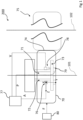
- Figure 1 shows an example of an apparatus 200 of testing a tyre 70 according to the invention.
- Figure 1 can exemplarily show a top view.
- the tyre 70 is mounted on a rim (not shown) and inflated to a, typically predetermined, pressure to obtain a vehicle wheel.
- the apparatus 200 comprises a rotor 71 rotatably fixed to a stator 72 for being able to rotate around an axis of rotation 101.
- the rotor 71 comprises an attachment portion 73 configured for mounting the rim.
- the apparatus 200 comprises a rolling wheel 75 having a respective axis of rotation 102 parallel to the axis of rotation 101 of the rotor 71.
- the axes of rotation 101 and 102 are static.
- the apparatus 200 comprises an acceleration sensor 76.
- the acceleration sensor 76 is triaxial and it is configured for separately detecting a tangential component, an axial component and a radial component of the linear acceleration, in figure 1 respectively directed along the X, Y and Z axes.
- the acceleration sensor 76 is mounted on the stator 72 (for example onto the outer surface of the stator 72), for example at an end of the stator 72 proximal to the attachment portion 73 of the rotor 71.
- the acceleration sensor can be mounted directly onto the rotor 71, or onto the rim, or again directly onto the tyre 70.
- the apparatus 200 comprises a processing unit 77 in communication with the acceleration sensor 76, for example by the communication line A (wireless or not), for receiving the accelerometric signal generated by the accelerometric sensor 76.
- a processing unit 77 is programmed and configured for performing the operations described below.
- the apparatus 200 comprises a thrust device 80 for imparting to the rotor 71 a thrust force F directed towards the rolling wheel 75.
- the thrust device can for example comprise one or more cylinders which, in use, act on the stator 72 which in turn transfers the thrust force to the rotor 71 and from this to the tyre 70, which is therefore kept in thrust against the rolling wheel 75.
- the apparatus 200 comprises a pressure sensor 79 configured for detecting a pressure of the tyre 70 and generating a pressure signal representative of the pressure.
- the pressure sensor 79 is in communication with the processing unit 77, for example by the communication line P (wireless or not), and it is applied on the filling valve of the tyre 70, the valve being mounted on the rim.
- the apparatus 200 comprises a speed sensor 78 configured for detecting a rotation speed of the tyre 70 and generating a speed signal representative of the rotation speed.
- the speed sensor is applied in part onto the rotor 71 and in part onto the stator 72.
- the speed sensor 78 is in communication with the processing unit, for example by the communication line V (wireless or not).
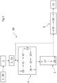
- Figure 2 shows a flow diagram of the operations of an example of a method 99 of testing a tyre 70 according to the present invention, which can be implemented with the apparatus 200 described above.
- the method 99 comprises mounting 1 the tyre 70 onto a rim and inflating 30 the tyre 70 to a pressure.
- the pressure of the tyre 70 is equal to the operating pressure of the specific tyre, for example about 200 kPa, and it is kept constant during the test.
- the method 99 comprises rotating the tyre 70 around an axis of rotation 101, with the tyre 70 in thrust with a force F on the rolling surface 74 of the rolling wheel 75.
- a force F exerted on the tyre is kept constant, for example equal to about 1000 kg.
- the rotation is characterized by a rotation speed of 10 round/s which defines a fundamental frequency equal to 10 Hz.
- the rotation speed is kept constant, for example with a maximum variation of 0.5 - 1 km/h.
- the rotation speed varies during the test, for example starting from 8 round/s up to 14 round/s, with increments (for example of 1 round/s) at regular intervals (for example every 200 minutes).
- increments for example of 1 round/s
- at each interval corresponds a different rotation speed which is kept constant during the interval and to which corresponds a different fundamental frequency (e.g. which varies from 8 Hz to 14 Hz).
- fundamental frequency e.g. which varies from 8 Hz to 14 Hz.
- the method described below can be exemplarily implemented separately for each interval (e.g. a respective reference spectrum for each interval).
- the rotation is characterized by a rotation period of about 0.1 seconds.
- the method 99 comprises acquiring an accelerometric signal 3 representative of a linear acceleration undergone by the tyre 70 during rotation.
- the accelerometric signal comprises all the following distinct accelerometric sub-signals: a first accelerometric sub-signal representative of a radial component of the linear acceleration, a second accelerometric sub-signal representative of an axial component of the linear acceleration and a third sub-accelerometric signal representative of a tangential component of the linear acceleration.
- only one and/or two components of the linear acceleration undergone by the tyre 70 can be detected, for example in case you want to analyse a specific damage of the tyre 70 which is more detectable on a component of the acceleration.
- each reference to the index refers to each respective index (IDP X , IDP Y , IDP Z ) and each reference to a spectrum (e.g. frequency spectrum or reference spectrum) refers to the respective spectrum.
- Exemplarily the method 99 comprises acquiring a speed signal 31 representative of the rotation speed of the tyre 70 (for example a signal of one pulse per turn).
- Exemplarily the speed signal and each of the accelerometric sub-signals are acquired on a time series of acquisition intervals wherein, exemplarily, each of the acquisition intervals has the same continuous duration of three minutes.
- each acquisition interval comprises about 1800 rotation periods.
- a time interval between the initial instants of two subsequent acquisition intervals is constant and equal to ten minutes.
- an operation e.g. calculating the spectrum or calculating the index
- an acquisition interval is intended to be performed on the respective data record acquired in that acquisition interval.
- Exemplarily the speed signal and each of the accelerometric sub-signals are acquired with an acquisition frequency of about 5000 Hz.
- the following operations are performed on the signal record of the subsequent acquisition interval.
- the method 99 comprises, separately for each of the accelerometric sub-signals, calculating a frequency spectrum 4.
- each of the frequency spectra comprises a fundamental harmonic having frequency equal to the fundamental frequency (preferably obtained from the speed signal).
- the method 99 first comprises calculating a variance 10 of each of the accelerometric sub-signals and accepting each of the accelerometric sub-signals if the variance is less than a given percentage value.
- Exemplarily the method 99 subsequently comprises filtering 11 each of the accelerometric sub-signals with a fourth-order Butterworth filter.
- the sampling 13 in synchronous way is performed, for example, with three-hundred points for each rotation period, so that the first and last of the sampled points always fall at the starting instant and the ending instant of the rotation period (obtained for example from the speed signal).
- Exemplarily calculating each frequency spectrum 4 comprises, subsequently to the sampling 13 in synchronous way, calculating a fast Fourier transform (FFT) 14, on each of the records of re-sampled accelerometric sub-signal.
- FFT fast Fourier transform
- each of the records of accelerometric sub-signal is partitioned into a predetermined number of (e.g. thirty) portions and the fast Fourier transform 14 is calculated on each portion.
- each portion corresponds to fifty consecutive rotation periods.
- Exemplarily calculating each frequency spectrum 4 comprises, separately for each sub-signal (and for each acquisition interval), averaging in terms of complex numbers 15 the fast Fourier transforms calculated on the predetermined number of portions of each accelerometric sub-signal.
- the result of this averaging in terms of complex numbers is an averaged frequency spectrum, characterized by amplitude values distributed in frequency.
- each of the averaged frequency spectra 16 a set of M amplitudes associated with M multiple integer harmonics of the consecutive fundamental harmonic starting from, and including, the fundamental harmonic is determined (and typically stored in the processing unit).
- M is equal to thirty.
- each amplitude is calculated integrating the amplitudes of the harmonics which fall into a neighbourhood around 10% of the value of the fundamental frequency and centred in the value of the respective nominal frequency of the respective integer multiple harmonic of the fundamental harmonic.
- the result of the calculation of the frequency spectrum can exemplarily consist of an M-tuple of real values which represent the amplitude of the first M (e.g. thirty) integer multiple harmonics of the fundamental harmonic.
- the method 99 comprises calculating a reference spectrum 17 of each accelerometric sub-signal at a reference condition.
- this reference condition provides the achievement of a structural and/or dimensional stability of the tyre during the test, while still remaining in a state of integrity.
- this reference condition can be temporally predetermined, for example it can correspond to the reference time interval that goes from the beginning to the end of the tenth hour starting from the beginning of the rotation of the tyre 70.
- the reference spectrum is obtained by averaging the frequency spectra (for example by averaging the M-tuples of amplitudes of the respective first M harmonics) calculated along six consecutive acquisition intervals, for example the acquisition intervals comprised between the ninth and tenth hour from the beginning of the rotation.
- the reference spectrum can exemplarily consist of an M-tuple of real values that represent the average value of the amplitudes of the first M harmonics of the frequency spectrum calculated for each acquisition interval exemplarily contained from the beginning to the end of the tenth hour from the start of the rolling test.
- Preferably method 99 comprises, for each acquisition interval, separately calculating an index 5 as a function of the frequency spectrum, comparing 18 the frequency spectrum with the reference spectrum.
- Exemplarily said comparing 18 comprises, for each acquisition interval:
- the time trend of the index is obtained calculating the index separately for each acquisition interval.
- Exemplarily the time trend of the index is obtained grouping 19 the acquisition intervals in a time series of groups of acquisition intervals consecutive to each other, exemplarily in number equal to six, and, for each group, performing 20 an average of the respective indexes calculated for each acquisition interval of the group.
- each current acquisition interval it is performed from time to time the average of the current index with the indexes calculated for exemplarily the five previous acquisition intervals (i.e. an average of the indexes is performed on a mobile window of, e.g., an hour).
- Exemplarily the method 99 comprises evaluating 6 in real time a possible presence of damages of the tyre 70 on the basis of the time trend of one or more of the three respective indexes (IDP X , IDP Y , IDP Z ).
- evaluating 6 the possible presence of damages of the tyre 70 is performed offline, based on a report generated as a function of the time trend of each index automatically by the processing unit at the end of the rolling test of the tyre.
- the possible presence of damages of the tyre is evaluated on the basis of a time trend of a combination of the respective indexes, for example of a linear sum of the three respective indexes.
- the tyre 70 is damaged when the time trend of one or more of the three respective indexes verifies a respective damage condition which for example verifies when a value of the respective index is greater than or equal to a respective threshold value, wherein each respective threshold value can be, for example, different from the others.
- the damage condition is verified when the value of one or more indexes changes rapidly over time, regardless of the achievement of the respective threshold value.
- Figures 3 , 4 and 5 show in graphic form the results of three exemplary rolling tests conducted by the Applicant according to the method described above.
- the figures show examples of the time trend of the three indexes (IDP X , IDP Y , IDP Z ), calculated starting from the accelerometric sub-signals acquired for the three components of the linear acceleration, respectively at three different damages generated in one tyre.
- the continuous line 300 shows the time trend of the IDP X index associated with the tangential component of the linear acceleration
- the dot line 301 shows the time trend of the IDP Y index associated with the axial component of the linear acceleration
- the dashed line 302 shows the time trend of the IDPz index associated with the radial component of the linear acceleration.
- Each datum that composes the lines 300, 301 and 302 corresponds to the value of the respective index in a respective acquisition interval of three minutes as explained above.
- the values on the horizontal axis represent the temporal instant (expressed in hours) starting from the instant subsequent to the reference condition (e.g. instant subsequent to the tenth hour) until the end of the test (i.e. achievement of the respective threshold value by one of the three indexes).
- the values on the vertical axis represent the values of the indexes expressed in arbitrary units, wherein the unit value represents the threshold value of the index which has reached its respective threshold value in the test.
- the indexes are averaged on a one-hour mobile window as described above.
- Figure 3 shows the time trend of the three indexes in the event of a damage to the tyre belt. As visible in the graph, the time trend of the index 300, associated to the tangential component of the acceleration, has reached the threshold value, thus verifying the damage condition, at approximately hour fifty-seven from the beginning of the rotation.
- Figure 4 shows the time trend of the three indexes in the event of a damage to the sidewall of the tyre. As visible in the graph, the time trend of the index 301, associated to the axial component of the acceleration, has reached the threshold value, thus verifying the damage condition, at approximately hour forty-eight from the beginning of the rotation.
- Figure 5 shows the time trend of the three indexes in the event of a fracture to the tyre belt.
- the time trend of the index 302 associated to the radial component of the acceleration, has reached the threshold value, thus verifying the damage condition, at approximately hour one-hundred-twenty-nine from the beginning of the rotation.
Landscapes
- Physics & Mathematics (AREA)
- General Physics & Mathematics (AREA)
- Tires In General (AREA)
- Testing Of Balance (AREA)
Claims (15)
- Procédé (99) pour tester un pneu (70), le procédé (99) comprenant :- le montage (1) dudit pneu (70) sur une jante et le gonflage (30) du pneu (70) à une pression ;- la mise en rotation (2) du pneu (70) autour d'un arbre rotatif (101), ledit pneu (70) étant en poussée avec une force sur une surface de roulement (74) ;- l'acquisition (3) d'un signal accélérométrique représentatif d'une accélération linéaire subie par ledit pneu (70) lors de ladite rotation ;- le calcul d'au moins un spectre de fréquence (4) dudit signal accélérométrique ;- le calcul d'au moins un indice (5) en fonction dudit au moins un spectre de fréquence ;- l'évaluation (6) d'un état d'intégrité dudit pneu (70) sur la base d'une tendance temporelle dudit au moins un indice,caractérisé en ce que le calcul dudit au moins un spectre de fréquence (4) comprend l'interpolation (12) dudit signal accélérométrique et, pour chaque période de ladite rotation, l'échantillonnage (13) dudit signal accélérométrique interpolé en un nombre donné de points, dans lequel ledit échantillonnage est effectué de manière synchrone avec ladite rotation.
- Procédé (99) selon la revendication 1, dans lequel ladite rotation est caractérisée par une vitesse de rotation qui définit une fréquence fondamentale, dans lequel ladite rotation est caractérisée par une période de rotation, dans lequel ledit au moins un spectre de fréquence comprend une harmonique fondamentale présentant une fréquence égale à ladite fréquence fondamentale, dans lequel ledit signal accélérométrique est acquis sur une série temporelle d'intervalles d'acquisition, dans lequel chaque intervalle d'acquisition comprend une pluralité de périodes de rotation, dans lequel chacun desdits intervalles d'acquisition présente une durée, de préférence continue, supérieure ou égale à 1 minute et/ou inférieure ou égale à 5 minutes, dans lequel lesdits intervalles d'acquisition présentent une même durée, dans lequel un intervalle de temps entre un instant initial respectif de deux intervalles d'acquisition ultérieurs est constant, de préférence il est supérieur ou égal à 5 minutes et/ou inférieur ou égal à 15 minutes, dans lequel il est prévu d'acquérir un signal de vitesse (31) représentatif de ladite vitesse de rotation dudit pneu, dans lequel ledit signal de vitesse est acquis sur ladite série temporelle d'intervalles d'acquisition, et dans lequel ledit signal de vitesse et/ou ledit signal accélérométrique est/sont acquis avec une fréquence d'acquisition supérieure ou égale à 4 000 Hz et/ou inférieure ou égale à 7 000 Hz, dans lequel il est prévu de déterminer ladite tendance temporelle du au moins un indice en effectuant ledit calcul d'au moins un spectre de fréquence (4) et ledit calcul d'au moins un indice (5), pour chacun desdits intervalles d'acquisition.
- Procédé (99) selon l'une quelconque des revendications précédentes, dans lequel le calcul dudit au moins un spectre de fréquence (4) comprend le calcul d'une variance (10) dudit signal accélérométrique et l'acceptation dudit signal accélérométrique en fonction de ladite variance, dans lequel le calcul dudit au moins un spectre de fréquence (4) comprend le filtrage (11) dudit signal accélérométrique à l'aide d'un filtre passe-bas.
- Procédé (99) selon l'une quelconque des revendications précédentes, dans lequel ledit calcul dudit au moins un spectre de fréquence (4) comprend le calcul d'une transformée de Fourier (14) sur ledit signal accélérométrique, dans lequel ladite transformée de Fourier est calculée sur une pluralité de portions dudit signal accélérométrique, chaque portion correspondant à un nombre entier de périodes de rotation consécutives, dans lequel ledit calcul dudit au moins un spectre de fréquence (4) comprend le calcul de la moyenne en termes de nombres complexes (15) desdites transformées de Fourier calculées sur ladite pluralité de portions de signal accélérométrique.
- Procédé (99) selon l'une quelconque des revendications précédentes, dans lequel le calcul dudit au moins un spectre de fréquence (4) comprend la détermination (16) d'un ensemble de M harmoniques, lesdits M harmoniques étant des multiples entiers d'une harmonique fondamentale consécutifs à partir de ladite harmonique fondamentale et l'incluant, dans lequel M est un entier supérieur ou égal à vingt et/ou inférieur ou égal à cinquante, dans lequel il est prévu de déterminer M amplitudes desdits M harmoniques, de préférence dans un spectre de fréquence moyenné obtenu par ledit calcul de la moyenne en termes de nombres complexes (15) desdites transformées de Fourier calculées sur ladite pluralité de portions de signal accélérométrique, dans lequel lesdites M amplitudes sont déterminées en intégrant les amplitudes des harmoniques qui tombent dans un voisinage d'une fréquence nominale respective du multiple entier d'harmonique respectif de l'harmonique fondamentale.
- Procédé (99) selon l'une quelconque des revendications précédentes, dans lequel le calcul dudit au moins un indice (5) comprend le calcul d'un spectre de référence (17) du signal accélérométrique à une condition de référence, dans lequel ladite condition de référence correspond à un état d'intégrité dudit pneu (70), dans lequel ledit pneu est dépourvu de dommages, dans lequel ladite condition de référence est prédéterminée temporellement, et dans lequel ladite condition de référence correspond à un intervalle de référence qui se situe après une cinquième heure et/ou avant une quinzième heure à partir du début de la rotation dudit pneu (70) en poussée sur ladite surface de roulement (74).
- Procédé (99) selon les revendications 2 et 6, dans lequel le calcul dudit spectre de référence (17) comprend le calcul de la moyenne d'une série de spectres de fréquence calculés séparément pour chaque intervalle d'acquisition d'une série d'intervalles d'acquisition consécutifs dans ladite condition de référence.
- Procédé (99) selon les revendications 2, 5 et l'une quelconque des revendications 6 ou 7, dans lequel ledit calcul dudit au moins un indice (5) comprend la comparaison (18), pour chacun desdits intervalles d'acquisition, dudit au moins un spectre de fréquence et dudit spectre de référence, dans lequel ladite comparaison (18) comprend, pour chaque intervalle d'acquisition, l'ordonnancement desdits M harmoniques dudit ensemble de M harmoniques par ordre décroissant d'amplitude, la sélection d'un sous-ensemble dudit ensemble ordonné de M harmoniques comprenant un nombre P d'harmoniques consécutives à partir de la première, dans lequel P est supérieur ou égal à six et/ou inférieur ou égal à trente, la sélection, dans ledit au moins un spectre de fréquence de chaque dit intervalle d'acquisition, d'un nombre P' d'harmoniques supplémentaires possibles dudit au moins un spectre de fréquence correspondant aux harmoniques appartenant aux sous-ensembles respectifs de P harmoniques dans les spectres de fréquence des intervalles d'acquisition précédant chaque dit intervalle d'acquisition et n'appartenant pas audit sous-ensemble de P harmoniques dans ledit au moins un spectre de fréquence, dans lequel P' est supérieur ou égal à 0 et/ou inférieur ou égal à M-P, etla comparaison de P amplitudes desdits P harmoniques dudit sous-ensemble et de P' amplitudes desdits P' harmoniques supplémentaires possibles avec des amplitudes respectives des harmoniques correspondantes dans ledit spectre de référence,dans lequel ladite comparaison (18) est effectuée en appliquant pour chaque intervalle d'acquisition, la formule :
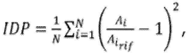 dans lequel IDP est ledit au moins un indice pour ledit intervalle d'acquisition ;N est un nombre supérieur ou égal audit nombre P d'harmoniques dudit sous-ensemble et inférieur ou égal audit nombre M d'harmoniques dudit ensemble ;A i est l'amplitude d'un ième harmonique desdits P harmoniques dudit sous-ensemble d'harmoniques et également desdits P' harmoniques supplémentaires possibles ;A i
rif est l'amplitude d'un ième harmonique dudit spectre de référence correspondant audit ième harmonique. - Procédé (99) selon l'une quelconque des revendications 2 à 8, dans lequel il est prévu d'obtenir ladite tendance temporelle dudit au moins un indice en regroupant (19) lesdits intervalles d'acquisition dans une série temporelle de groupes d'intervalles d'acquisition consécutifs les uns aux autres, dans lequel chaque groupe comprend un nombre donné d'intervalles d'acquisition, et en effectuant (20) pour chaque groupe une moyenne des indices calculés séparément pour chaque intervalle d'acquisition du groupe.
- Procédé (99) selon l'une quelconque des revendications précédentes, dans lequel il est prévu d'établir que ledit pneu (70) est endommagé à condition que ladite tendance temporelle du au moins un indice vérifie un état d'endommagement, dans lequel ledit état d'endommagement est vérifié lorsqu'une valeur dudit au moins un indice devient supérieure ou égale à une valeur seuil pour ledit indice, dans lequel ladite évaluation (6) dudit état d'intégrité dudit pneu (70) sur la base de la tendance temporelle du au moins un indice est effectuée en temps réel, dans lequel il est prévu d'interrompre ladite rotation du pneu (70) lorsque ladite tendance temporelle du au moins un indice vérifie un état d'endommagement, et dans lequel il est prévu de générer un signal d'alarme à la suite dudit établissement que ledit pneu est endommagé.
- Procédé (99) selon l'une quelconque des revendications précédentes, dans lequel il est prévu de fournir un rotor (71) fixé de manière rotative à un stator (72) pour pouvoir tourner autour dudit arbre rotatif (101), en montant ladite jante sur une partie de fixation (73) dudit rotor (71), dans lequel ledit signal accélérométrique est acquis sur ledit stator (72), dans lequel il est prévu de fournir une roue de roulement (75) présentant un arbre rotatif respectif (102) parallèle audit arbre rotatif (101), dans lequel ladite surface de roulement (74) fait partie de ladite roue de roulement (75).
- Procédé (99) selon l'une quelconque des revendications précédentes, dans lequel ledit signal accélérométrique comprend un ou plusieurs des sous-signaux accélérométriques distincts suivants : un premier sous-signal accélérométrique représentatif d'une composante radiale de ladite accélération linéaire, un deuxième sous-signal accélérométrique représentatif d'une composante axiale de ladite accélération linéaire et un troisième sous-signal accélérométrique représentatif d'une composante tangentielle de ladite accélération linéaire, et dans lequel le calcul dudit au moins un spectre de fréquence (4) dudit signal accélérométrique comprend le calcul séparé d'un spectre de fréquence respectif pour chacun desdits sous-signaux accélérométriques, dans lequel le calcul dudit au moins un indice en fonction dudit au moins un spectre de fréquence (5) comprend le calcul séparé d'un indice respectif en fonction de chaque spectre de fréquence respectif, et dans lequel l'évaluation (6) de l'état d'intégrité dudit pneu (70) sur la base de ladite tendance temporelle dudit au moins un indice comprend l'évaluation de l'état d'intégrité dudit pneu (70) sur la base d'une tendance temporelle d'un ou plusieurs desdits indices respectifs.
- Appareil (200) pour tester un pneu (70), l'appareil comprenant :- un rotor (71) fixé de manière rotative à un stator (72) pour pouvoir tourner autour d'un arbre rotatif (101), dans lequel le rotor (71) comprend une partie de fixation (73) configurée pour monter une jante sur laquelle ledit pneu (70) est monté ;- une roue de roulement (75) présentant un arbre rotatif respectif (102) parallèle audit arbre rotatif (101) ;- un capteur d'accélération (76) configuré pour détecter une accélération linéaire subie par ledit rotor (71) en rotation et pour générer un signal accélérométrique représentatif de ladite accélération linéaire ;- une unité de traitement (77) en communication avec ledit capteur d'accélération (76) pour acquérir ledit signal accélérométrique, dans lequel l'unité de traitement (77) est programmée et configurée pour, lorsque ledit pneu (70) est en rotation et en poussée avec une force sur une surface de roulement (74) de la roue de roulement (75) :caractérisé en ce que le calcul dudit au moins un spectre de fréquence (4) comprend l'interpolation (12) dudit signal accélérométrique et, pour chaque période de ladite rotation, l'échantillonnage (13) dudit signal accélérométrique interpolé en un nombre donné de points, dans lequel ledit échantillonnage est effectué de manière synchrone avec ladite rotation.- le calcul d'au moins un spectre de fréquence (4) dudit signal accélérométrique ;- le calcul d'au moins un indice (5) en fonction dudit au moins un spectre de fréquence ;- l'évaluation (6) d'un état d'intégrité dudit pneu (70) sur la base d'une tendance temporelle dudit au moins un indice,
- Appareil (200) selon la revendication 13, dans lequel ladite unité de traitement (77) est programmée et configurée pour effectuer une ou plusieurs des opérations prévues dans le procédé (99) selon une ou plusieurs des revendications 2 à 12.
- Appareil (200) selon l'une quelconque des revendications 13 ou 14, dans lequel ledit capteur d'accélération (76) est configuré pour détecter séparément une ou plusieurs parmi une composante axiale, une composante radiale et une composante tangentielle de ladite accélération linéaire, dans lequel ledit capteur d'accélération (76) est monté sur ledit stator (71), dans lequel l'appareil (200) comprend un capteur de vitesse (78) configuré pour détecter une vitesse de rotation dudit pneu (70) et générer un signal de vitesse représentatif de ladite vitesse de rotation, dans lequel ledit capteur de vitesse (78) est appliqué en partie sur ledit stator (72) et en partie sur ledit rotor (71), et dans lequel ladite unité de traitement (77) est en communication avec ledit capteur de vitesse (78) pour acquérir ledit signal de vitesse, dans lequel ledit appareil (200) comprend un dispositif de poussée (80) pour communiquer sur ledit rotor (71) une force de poussée (F) dirigée vers ladite roue de roulement (75), dans lequel ladite force (F) est constante et choisie en fonction d'un indice de charge dudit pneu, dans lequel ledit appareil (200) comprend un capteur de pression (79) pour détecter une pression dudit pneu (70) et générer un signal de pression représentatif de ladite pression, dans lequel ladite unité de traitement (77) est en communication avec ledit capteur de pression (79) pour acquérir ledit signal de pression, et pour maintenir constante ladite pression.
Priority Applications (1)
| Application Number | Priority Date | Filing Date | Title |
|---|---|---|---|
| EP24205827.9A EP4484917A3 (fr) | 2019-08-05 | 2020-07-24 | Procédé de contrôle d'un pneumatique |
Applications Claiming Priority (2)
| Application Number | Priority Date | Filing Date | Title |
|---|---|---|---|
| IT201900014049 | 2019-08-05 | ||
| PCT/IT2020/050184 WO2021024283A1 (fr) | 2019-08-05 | 2020-07-24 | Procédé d'essai d'un pneu |
Related Child Applications (1)
| Application Number | Title | Priority Date | Filing Date |
|---|---|---|---|
| EP24205827.9A Division EP4484917A3 (fr) | 2019-08-05 | 2020-07-24 | Procédé de contrôle d'un pneumatique |
Publications (3)
| Publication Number | Publication Date |
|---|---|
| EP4010678A1 EP4010678A1 (fr) | 2022-06-15 |
| EP4010678C0 EP4010678C0 (fr) | 2024-11-06 |
| EP4010678B1 true EP4010678B1 (fr) | 2024-11-06 |
Family
ID=69158164
Family Applications (2)
| Application Number | Title | Priority Date | Filing Date |
|---|---|---|---|
| EP24205827.9A Pending EP4484917A3 (fr) | 2019-08-05 | 2020-07-24 | Procédé de contrôle d'un pneumatique |
| EP20750373.1A Active EP4010678B1 (fr) | 2019-08-05 | 2020-07-24 | Procédé d'essai d'un pneu |
Family Applications Before (1)
| Application Number | Title | Priority Date | Filing Date |
|---|---|---|---|
| EP24205827.9A Pending EP4484917A3 (fr) | 2019-08-05 | 2020-07-24 | Procédé de contrôle d'un pneumatique |
Country Status (3)
| Country | Link |
|---|---|
| EP (2) | EP4484917A3 (fr) |
| CN (2) | CN121347172A (fr) |
| WO (1) | WO2021024283A1 (fr) |
Families Citing this family (2)
| Publication number | Priority date | Publication date | Assignee | Title |
|---|---|---|---|---|
| CN115452300B (zh) * | 2022-08-23 | 2025-06-03 | 青岛森麒麟轮胎股份有限公司 | 轮胎动态冲击试验的测试方法 |
| CN116698448A (zh) * | 2023-05-16 | 2023-09-05 | 安徽佳通乘用子午线轮胎有限公司 | 一种轮胎损坏预警系统及方法 |
Family Cites Families (6)
| Publication number | Priority date | Publication date | Assignee | Title |
|---|---|---|---|---|
| WO2001006208A1 (fr) * | 1999-07-16 | 2001-01-25 | Test Measurement Systems, Inc. | Procede et systemes de mesure de forces dynamiques |
| US6655202B2 (en) | 2000-06-08 | 2003-12-02 | Bridgestone/Firestone North American Tire, Llc | Dynamic force measurement system for tire testing station |
| JP4104446B2 (ja) * | 2002-12-13 | 2008-06-18 | 横浜ゴム株式会社 | タイヤ試験装置およびタイヤ試験方法 |
| US7272536B2 (en) * | 2005-05-23 | 2007-09-18 | Potts Gerald R | Failure warning for a tire among a plurality of tires |
| JP2007064877A (ja) * | 2005-09-01 | 2007-03-15 | Yokohama Rubber Co Ltd:The | タイヤの故障発生検知方法およびタイヤの故障発生検知装置 |
| JP5495971B2 (ja) * | 2010-06-24 | 2014-05-21 | 株式会社ブリヂストン | タイヤ内部故障判定方法 |
-
2020
- 2020-07-24 CN CN202511685568.6A patent/CN121347172A/zh active Pending
- 2020-07-24 EP EP24205827.9A patent/EP4484917A3/fr active Pending
- 2020-07-24 EP EP20750373.1A patent/EP4010678B1/fr active Active
- 2020-07-24 WO PCT/IT2020/050184 patent/WO2021024283A1/fr not_active Ceased
- 2020-07-24 CN CN202080062617.XA patent/CN114341612B/zh active Active
Also Published As
| Publication number | Publication date |
|---|---|
| EP4010678A1 (fr) | 2022-06-15 |
| EP4010678C0 (fr) | 2024-11-06 |
| CN114341612A (zh) | 2022-04-12 |
| CN114341612B (zh) | 2025-10-28 |
| CN121347172A (zh) | 2026-01-16 |
| EP4484917A2 (fr) | 2025-01-01 |
| EP4484917A3 (fr) | 2025-03-12 |
| WO2021024283A1 (fr) | 2021-02-11 |
Similar Documents
| Publication | Publication Date | Title |
|---|---|---|
| US4815004A (en) | Apparatus and method for predicting fore/aft forces generated by tires | |
| RU2558007C2 (ru) | Способ обнаружения повреждения, по меньшей мере, одного опорного подшипника двигателя | |
| US8285498B2 (en) | Method for detection and automatic identification of damage to rolling bearings | |
| US11105712B2 (en) | Integrated vibe/ODM fusion and trending analysis for prognostic health management of engine bearing | |
| JP6087163B2 (ja) | タイヤユニフォミティマシンを特性化するためのシステムおよびその特性化を使用する方法 | |
| US5396438A (en) | Tire manufacturing method | |
| EP4010678B1 (fr) | Procédé d'essai d'un pneu | |
| US7272536B2 (en) | Failure warning for a tire among a plurality of tires | |
| EP3163282B1 (fr) | Procede de caracterisation de machines d'uniformite de pneu | |
| US5845232A (en) | Apparatus and method for detecting splice overlaps or splice gaps in a tire | |
| CN115931399B (zh) | 一种实时在线检测高速列车轮多边形故障的方法 | |
| US4702103A (en) | Method of quality grading in uniformity tests of rotors, in particular of automobile tires | |
| EP4271575B1 (fr) | Procédé et système de surveillance d'un état de pneu | |
| CN112660199B (zh) | 轨道交通牵引电机轴承状态监测的数据存储及预报警方法 | |
| EP4271577B1 (fr) | Procédé et système de surveillance d'un état d'un pneumatique | |
| JP2007064877A (ja) | タイヤの故障発生検知方法およびタイヤの故障発生検知装置 | |
| CN212134087U (zh) | 一种基于里程试验机上的轮胎稳态轮廓检测设备 | |
| EP3006234B1 (fr) | Procédé de détermination de charge anormale de véhicules | |
| JP2947508B2 (ja) | ギアの噛合せ検査方法 | |
| EP4271576B1 (fr) | Procédé de surveillance de l'état d'un pneu | |
| JP2967969B2 (ja) | ギアの噛合せ検査方法 | |
| Johnson et al. | Composite indices applied to vibration data in rolling tires to detect bead area damage | |
| RU2760255C2 (ru) | Способ диагностики состояния накачки шины транспортного средства | |
| JPS63138230A (ja) | 自動車の振動解析装置 | |
| Ganeriwala et al. | Using operating deflection shapes to detect faults in rotating equipment |
Legal Events
| Date | Code | Title | Description |
|---|---|---|---|
| STAA | Information on the status of an ep patent application or granted ep patent |
Free format text: STATUS: UNKNOWN |
|
| STAA | Information on the status of an ep patent application or granted ep patent |
Free format text: STATUS: THE INTERNATIONAL PUBLICATION HAS BEEN MADE |
|
| PUAI | Public reference made under article 153(3) epc to a published international application that has entered the european phase |
Free format text: ORIGINAL CODE: 0009012 |
|
| STAA | Information on the status of an ep patent application or granted ep patent |
Free format text: STATUS: REQUEST FOR EXAMINATION WAS MADE |
|
| 17P | Request for examination filed |
Effective date: 20220131 |
|
| AK | Designated contracting states |
Kind code of ref document: A1 Designated state(s): AL AT BE BG CH CY CZ DE DK EE ES FI FR GB GR HR HU IE IS IT LI LT LU LV MC MK MT NL NO PL PT RO RS SE SI SK SM TR |
|
| DAV | Request for validation of the european patent (deleted) | ||
| DAX | Request for extension of the european patent (deleted) | ||
| GRAP | Despatch of communication of intention to grant a patent |
Free format text: ORIGINAL CODE: EPIDOSNIGR1 |
|
| STAA | Information on the status of an ep patent application or granted ep patent |
Free format text: STATUS: GRANT OF PATENT IS INTENDED |
|
| INTG | Intention to grant announced |
Effective date: 20240624 |
|
| GRAS | Grant fee paid |
Free format text: ORIGINAL CODE: EPIDOSNIGR3 |
|
| GRAA | (expected) grant |
Free format text: ORIGINAL CODE: 0009210 |
|
| STAA | Information on the status of an ep patent application or granted ep patent |
Free format text: STATUS: THE PATENT HAS BEEN GRANTED |
|
| AK | Designated contracting states |
Kind code of ref document: B1 Designated state(s): AL AT BE BG CH CY CZ DE DK EE ES FI FR GB GR HR HU IE IS IT LI LT LU LV MC MK MT NL NO PL PT RO RS SE SI SK SM TR |
|
| REG | Reference to a national code |
Ref country code: GB Ref legal event code: FG4D |
|
| REG | Reference to a national code |
Ref country code: CH Ref legal event code: EP |
|
| REG | Reference to a national code |
Ref country code: DE Ref legal event code: R096 Ref document number: 602020040854 Country of ref document: DE |
|
| REG | Reference to a national code |
Ref country code: IE Ref legal event code: FG4D |
|
| U01 | Request for unitary effect filed |
Effective date: 20241113 |
|
| U07 | Unitary effect registered |
Designated state(s): AT BE BG DE DK EE FI FR IT LT LU LV MT NL PT RO SE SI Effective date: 20241119 |
|
| PG25 | Lapsed in a contracting state [announced via postgrant information from national office to epo] |
Ref country code: HR Free format text: LAPSE BECAUSE OF FAILURE TO SUBMIT A TRANSLATION OF THE DESCRIPTION OR TO PAY THE FEE WITHIN THE PRESCRIBED TIME-LIMIT Effective date: 20241106 Ref country code: IS Free format text: LAPSE BECAUSE OF FAILURE TO SUBMIT A TRANSLATION OF THE DESCRIPTION OR TO PAY THE FEE WITHIN THE PRESCRIBED TIME-LIMIT Effective date: 20250306 |
|
| PG25 | Lapsed in a contracting state [announced via postgrant information from national office to epo] |
Ref country code: ES Free format text: LAPSE BECAUSE OF FAILURE TO SUBMIT A TRANSLATION OF THE DESCRIPTION OR TO PAY THE FEE WITHIN THE PRESCRIBED TIME-LIMIT Effective date: 20241106 |
|
| PG25 | Lapsed in a contracting state [announced via postgrant information from national office to epo] |
Ref country code: NO Free format text: LAPSE BECAUSE OF FAILURE TO SUBMIT A TRANSLATION OF THE DESCRIPTION OR TO PAY THE FEE WITHIN THE PRESCRIBED TIME-LIMIT Effective date: 20250206 |
|
| PG25 | Lapsed in a contracting state [announced via postgrant information from national office to epo] |
Ref country code: GR Free format text: LAPSE BECAUSE OF FAILURE TO SUBMIT A TRANSLATION OF THE DESCRIPTION OR TO PAY THE FEE WITHIN THE PRESCRIBED TIME-LIMIT Effective date: 20250207 |
|
| PG25 | Lapsed in a contracting state [announced via postgrant information from national office to epo] |
Ref country code: PL Free format text: LAPSE BECAUSE OF FAILURE TO SUBMIT A TRANSLATION OF THE DESCRIPTION OR TO PAY THE FEE WITHIN THE PRESCRIBED TIME-LIMIT Effective date: 20241106 |
|
| PG25 | Lapsed in a contracting state [announced via postgrant information from national office to epo] |
Ref country code: RS Free format text: LAPSE BECAUSE OF FAILURE TO SUBMIT A TRANSLATION OF THE DESCRIPTION OR TO PAY THE FEE WITHIN THE PRESCRIBED TIME-LIMIT Effective date: 20250206 |
|
| PG25 | Lapsed in a contracting state [announced via postgrant information from national office to epo] |
Ref country code: SM Free format text: LAPSE BECAUSE OF FAILURE TO SUBMIT A TRANSLATION OF THE DESCRIPTION OR TO PAY THE FEE WITHIN THE PRESCRIBED TIME-LIMIT Effective date: 20241106 |
|
| PG25 | Lapsed in a contracting state [announced via postgrant information from national office to epo] |
Ref country code: SK Free format text: LAPSE BECAUSE OF FAILURE TO SUBMIT A TRANSLATION OF THE DESCRIPTION OR TO PAY THE FEE WITHIN THE PRESCRIBED TIME-LIMIT Effective date: 20241106 |
|
| PG25 | Lapsed in a contracting state [announced via postgrant information from national office to epo] |
Ref country code: CZ Free format text: LAPSE BECAUSE OF FAILURE TO SUBMIT A TRANSLATION OF THE DESCRIPTION OR TO PAY THE FEE WITHIN THE PRESCRIBED TIME-LIMIT Effective date: 20241106 |
|
| U20 | Renewal fee for the european patent with unitary effect paid |
Year of fee payment: 6 Effective date: 20250728 |
|
| PLBE | No opposition filed within time limit |
Free format text: ORIGINAL CODE: 0009261 |
|
| STAA | Information on the status of an ep patent application or granted ep patent |
Free format text: STATUS: NO OPPOSITION FILED WITHIN TIME LIMIT |
|
| 26N | No opposition filed |
Effective date: 20250807 |
|
| PGFP | Annual fee paid to national office [announced via postgrant information from national office to epo] |
Ref country code: GB Payment date: 20250728 Year of fee payment: 6 |
|
| REG | Reference to a national code |
Ref country code: CH Ref legal event code: H13 Free format text: ST27 STATUS EVENT CODE: U-0-0-H10-H13 (AS PROVIDED BY THE NATIONAL OFFICE) Effective date: 20260224 |
|
| PG25 | Lapsed in a contracting state [announced via postgrant information from national office to epo] |
Ref country code: CH Free format text: LAPSE BECAUSE OF NON-PAYMENT OF DUE FEES Effective date: 20250731 |