EP4010759B1 - Brille mit sandwichartiger polymerstruktur - Google Patents
Brille mit sandwichartiger polymerstruktur Download PDFInfo
- Publication number
- EP4010759B1 EP4010759B1 EP20757241.3A EP20757241A EP4010759B1 EP 4010759 B1 EP4010759 B1 EP 4010759B1 EP 20757241 A EP20757241 A EP 20757241A EP 4010759 B1 EP4010759 B1 EP 4010759B1
- Authority
- EP
- European Patent Office
- Prior art keywords
- spectacle lens
- cover member
- actuators
- transparent cover
- lens according
- Prior art date
- Legal status (The legal status is an assumption and is not a legal conclusion. Google has not performed a legal analysis and makes no representation as to the accuracy of the status listed.)
- Active
Links
Images


Classifications
-
- G—PHYSICS
- G02—OPTICS
- G02C—SPECTACLES; SUNGLASSES OR GOGGLES INSOFAR AS THEY HAVE THE SAME FEATURES AS SPECTACLES; CONTACT LENSES
- G02C7/00—Optical parts
- G02C7/02—Lenses; Lens systems ; Methods of designing lenses
- G02C7/08—Auxiliary lenses; Arrangements for varying focal length
- G02C7/081—Ophthalmic lenses with variable focal length
- G02C7/085—Fluid-filled lenses, e.g. electro-wetting lenses
-
- G—PHYSICS
- G02—OPTICS
- G02C—SPECTACLES; SUNGLASSES OR GOGGLES INSOFAR AS THEY HAVE THE SAME FEATURES AS SPECTACLES; CONTACT LENSES
- G02C7/00—Optical parts
- G02C7/02—Lenses; Lens systems ; Methods of designing lenses
- G02C7/08—Auxiliary lenses; Arrangements for varying focal length
- G02C7/081—Ophthalmic lenses with variable focal length
-
- G—PHYSICS
- G02—OPTICS
- G02B—OPTICAL ELEMENTS, SYSTEMS OR APPARATUS
- G02B26/00—Optical devices or arrangements for the control of light using movable or deformable optical elements
- G02B26/06—Optical devices or arrangements for the control of light using movable or deformable optical elements for controlling the phase of light
-
- G—PHYSICS
- G02—OPTICS
- G02B—OPTICAL ELEMENTS, SYSTEMS OR APPARATUS
- G02B3/00—Simple or compound lenses
- G02B3/12—Fluid-filled or evacuated lenses
- G02B3/14—Fluid-filled or evacuated lenses of variable focal length
Definitions
- the invention relates to spectacles, particularly spectacles configured with lenses of which the optical power is adjustable.
- the capability of the eye to focus on objects at different distances may be limited of different reasons. Typically, this capability is reduced as a function of age. Then it may be necessary to use different spectacles having different optical powers, or spectacles with different or variable optical powers like bifocal or progressive spectacles.
- WO 2019/002448 A1 discloses a tunable lens with two transparent cover members, a piezoelectric actuator system, a rigid frame and a non-fluid body which may be used in spectacles.
- WO 2013/144533 A1 a liquid filled adjustable spectacles lens with deformable non-round membrane assembly in which the shape of a membrane is controllably adjustable by altering the fluid pressure across the membrane.
- WO 95/27912 A1 discloses a mechanically tunable spectacle lens.
- bending piezo-electric elements are arranged in a pattern on the transparent cover which shape the tunable lens body.
- WO 2008/035983 A1 discloses a tunable lens in which the actuator is applying a force upon the flexible layer for bending the layer.
- a spectacle lens which comprises
- controllable actuators enables control of the optical power of the lenses in a pair of spectacles implying that the optical power of the lenses can be changed without the user needs to gaze through different portions of the lenses to access different optical powers as in traditional multi-focal or progressive lenses.
- the transparent, deformable, non-fluid body supports the bending of the first or second cover member so that the resulting curvature of the bending approximates a spherical shape. That is, polymers which are used for the non-fluid body creates a non-uniform distribution of the force applied to the cover members when actuators are activated. In comparison, the hydrostatic pressure in liquid is the same everywhere in liquid. A non-uniform force distribution can be advantageous in some situations to create a spherical deformation profile. Further, the non-fluid body is not significantly sensitive to gravity as compared with liquid. Thus, optical errors due to gravity effects is limited due to use of the non-fluid body.
- the one or more actuators are arranged to generate the forces or torques on the first or the second cover member along a circumference of the first or the second cover member so as to generate a controllable change of curvature of the first or the second cover member.
- the sliding contact arranged to allow displacement of the distal surface or the proximal surface relative to the one or more actuators is according to the invention.
- the proximal surface and/or the distal surface are inwardly curved when seen from the eye.
- the one of the first and second transparent cover member on which the one or more actuators act is bendable by the generated forces or torques of the one or more actuators, and the other of the first and second transparent cover member is shaped to provide a static optical correction.
- the one of the first and second transparent cover member on which the one or more actuators act is supported on the distal surface or the proximal surface, respectively, by a sliding contact which allows a displacement of the distal surface or the proximal surface along the surface relative to the actuator.
- the spectacle lens is arranged so that the non-fluid body is able to expand unconstrained in an annular volume located between the first and second transparent cover members and surrounding the non-fluid body.
- the spectacle lens is arranged so that light from the exterior travelling through the spectacle lens towards an eye is refracted through a sandwich structure consisting of the first and second transparent cover members and the non-fluid body, optionally including optical coatings on the distal surfaces of the first and second transparent cover members.
- the simple design of the spectacle lens provides a solution few components.
- at least one of the first and second transparent cover members has an initial curved shape so that the spectacle lens has a non-zero optical power when the one or more actuators provide a zero or minimum force on the first or second cover member.
- At least one of the first and second transparent cover members has a concave or convex shaped portion abutting the non-fluid body.
- the one or more actuators are controllable to generate at least two predetermined optical powers of the spectacle lens.
- the spectacle lens is optimized to generate minimum optical errors at the at least two predetermined optical powers.
- the one or more actuators are controlled via a control or power signal, where the control or power signal is determined as a function of measured data.
- the one or more actuators are controlled via a control signal, where the control signal is determined as a function of an error between a desired optical power of the spectacle lens and measured data relating to the actual optical power.
- the actuators are linear displacement motors capable of maintaining an achieved curvature of the first or the second transparent cover member in a non-powered state.
- a minimum diameter of a line extending from one edge to an opposite edge and crossing a center point of the spectacle lens is 15 mm.
- the sliding contact comprises one or more elastic elements connecting the one or more actuators with the distal surface and/or the proximal surface.
- a second aspect of the invention relates to a spectacle comprising
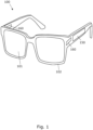
- Fig. 1 shows a pair of spectacles 100 comprising two spectacle lenses 101 mounted in a spectacle frame 102.
- the pair of spectacles 100 further comprises a power and control circuit 150, which may be integrated in the frame 102, for powering and controlling one or more actuators 160 arranged to generate forces acting on one or more of the lenses 101 in order to generate a controllable change of the optical power of the lenses 101.
- the power and control circuit 150 and the actuators 160 are principally illustrated.
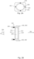
- Fig. 2A shows a front view of one of the spectacle lenses 101
- Fig. 2B shows a side view or cross-sectional view of the lens 101.
- the lens comprises a first transparent cover member 211, and a second transparent cover member 212.
- the first transparent cover member 211 is defined as the cover member which is located next to the eye 290, when in use.
- the second cover member 212 is defined as the cover member which is located nearest the surroundings, i.e. the object space, when in use.
- the outwardly facing surface of the first transparent cover member 211 is defined as a proximal surface 213 which faces the eye 290 when in use.
- the outwardly facing surface of the second transparent cover member 211 is defined as a distal surface 214 which faces the surroundings when in use.
- the lens 101 comprises a transparent, deformable, non-fluid body 205 sandwiched between the first and second transparent cover members 211, 212.
- the non-fluid body 205 abuts the inwardly facing surfaces of the first and second cover members 211, 212.
- the one or more actuators 160 are arranged to generate forces or torques on the first or the second cover member 211, 212 along a circumference 261 of the first or the second cover member.
- the actuators 160 may be linear displacement actuators, such as linear piezoelectric motors, arranged to apply a displacement at several points, here four points are illustrated, along the circumference 261.
- the circumference 261 may located outside the transparent, deformable, non-fluid body 205 so that the non-fluid body 205 is surrounded by the circumference as illustrated. However, the circumference 261 could also be located within the extension of the non-fluid body 205. The actuators 160 could also be located so that they act on the edge 219 of the first or second cover member 211, 212.
- the circumference 261 is understood as a path which surrounds at least a portion of the non-fluid body, such as a portion which comprises the optical axis 291 or a center portion of the non-fluid body.
- actuators act on a frame or mount that transfer the force to the lenses 101 are also possible.
- force or torque from a single actuator could be distributed to the cover members 211, 212.
- the frame or mount could covert rotation of a rotational actuator into linear displacement.
- the actuators 160 are arranged to generate the displacement along the circumference 261 in a direction normal or substantially normal to one of the surfaces, e.g. the proximal or distal surface 213, 214. Substantially normal, in this context, may imply deviations relative to the normal by up to e.g. 10-15 degrees. Other configurations where the actuators act on the edge 219, e.g. an actuator comprising a tightening belt which at least partly circumscribes the edge 219, are also possible. Thus, in such other configurations the actuators may be arranged to generate forces acting in the plane of the cover member 211, 212.
- the action of the actuators changes the curvature of the first or the second cover member dependent on the force, torque or displacement provided by the actuators.
- the actuators by controlling the actuators, the bending and thereby the optical power of the lens 101 can be controlled.
- the one of the first and second membrane which is not in contact with the actuators 160 may be supported by a portion of the spectacles frame 202, i.e. so that the this first or second membrane is fixed to the frame 102.
- Fig. 2B shows that the second membrane 212 is fixed to the frame 102, 202 and that the first membrane 211 is connected to the one or more actuators 160.
- the first membrane 211 is fixed to the frame 102, 202 and the second membrane 212 is connected to the one or more actuators 160.
- the actuators are arranged to act on both the first and second membranes 211, 212 so that both membranes are forced to bend by the action of the actuators 160, possibly so that actuators on either side are controllable independently, i.e. so that the displacement/force applied on one of the cover members is independent of the displacement/force applied on the other.
- Fig. 5A An example of such a solution is illustrated in Fig. 5A , where the actuators are fixed to the frame 120, 202 of the spectacles and the cover members 211, 212 are fixed to the actuators.
- Fig. 5B illustrates another actuator 160 embodied by one or more elements 501 arranged along the circumference 261.
- the actuator 160 may be embodied by a ring shaped actuator element 501 such as a ring shaped piezo element which is attached to the proximal and/or the distal surfaces 213, 214 of the first and/or second cover member 211, 212.
- the elements contracts or expands radially (e.g. in a plane perpendicular to the optical axis 291), essentially rotation symmetric relative to the optical axis 291.
- the generated contractile or expansive forces T are transferred to the cover members 211, 212 and cause bending due to the torques generated by the forces T.
- the lenses 101 in Fig. 5B may be connected to the frame via the elements 501 as in Fig. 5A , e.g. when both of the cover members comprise elements 501, or via the cover member as in Fig. 3B when this cover member does not have elements 501.
- Fig. 5A and 5B are described in more detail in Figs. 3D-E .
- the lens 101 defines an optical axis 291.
- the optical axis can be seen as the axis that light propagates along from the object space towards the eye 290, at least for some paraxial light rays.
- the plane or curved surfaces of the first and second transparent membranes 211, 212 such as the plane or curved proximal/distal surfaces 213, 214, may - on at least one surface point - define a plane or tangent plane which is normal to the optical axis 291, or at least define a plane or tangent plane which makes an acute angle with a plane which is normal to the optical axis 291.
- the planes of the first and second transparent membranes 211, 212 generally extends along a direction perpendicular to the optical axis 291.
- the transparent deformable, non-fluid lens body 205 is preferably made from an elastic material. Since the lens body is non-fluid, no fluid-tight enclosure is needed to hold the lens body, and there is no risk of leakage.
- the lens body is made from a soft polymer, which may include a number of different materials, such as silicone, polymer gels, a polymer network of cross-linked or partly cross-linked polymers, and a miscible oil or combination of oils.
- the elastic modulus of the non-fluid lens body may be larger than 300 Pa, thereby avoiding deformation due to gravitational forces in normal operation.
- the refractive index of the non-fluid lens body may be larger than 1.3.
- the non-fluid body 205 may have a refractive index which is equal, substantially equal or close to the refractive index of the transparent cover members 211, 212 in order to reduce reflections at the boundaries of the non-fluid body 205.
- the transparent cover members 211, 212 may be made from a large number of different materials, such as acrylics, polyolefins, polyesters, silicones, polyurethanes, glass and others. At least the one of the first and second cover members 211, 212 which is arranged to be deformed by the actuators, has a stiffness and thickness suitable to enable bending by actuation of the actuators 160.
- the material of the first and/or the second cover member 211, 212 may be formed in a material having a Young's modulus in the range between 5 MPa and 100 GPa to provide the necessary stiffness. For example, Young's modulus for borosilicate glass is 63 GPa, and 72 GPa for fused silica glass.
- the bending of the first and/or second cover members 211, 212 is at least partly due to radially varying reaction forces from the non-fluid lens body 105 which affects the Sag of the cover members 111, 112 and thus the optical power instead of just vertically compressing the lens body with no change in Sag.
- a full explanation of the effect of the lens body 105 on the curvature of the cover members is described in WO2019002524A1 .
- the material of the non-fluid lens body 105 is substantially incompressible. This incompressibility is at least partly responsible for the capability of bending the first and/or second cover members 211, 212 in a shape which provides the effect of an optical lens.
- the lens 101 may comprise coatings such as antireflection coatings applied on the proximal surface 213 and/or the distal surface 214.
- the transparent cover members 211, 212 are generally slab-shaped and may have curved or plane surfaces or a combination thereof.
- the slab-shaped cover members comprises first and second surfaces, e.g. the distal surface 214 and the inner surface 216, and an edge, where the curvature extends along at least one direction on at least one of the surfaces.
- the transparent cover members 211, 212 may be curved along only one direction or along two directions.
- one or both of the first and second surfaces may be plane.
- one or both of the cover members 211, 212 may constitute a plano-convex or plano-concave lens.
- the thickness of the cover member which is arranged to be bend by the actuators may be in the range from 0.1mm to 2mm or up to 10mm although other thicknesses are also possible.
- the spectacle lenses 101 may have a minimum diameter defined by a line extending from one edge to an opposite edge and crossing a center point of the spectacle lens of 15 mm. I.e. the minimum diameter of the lenses 101 are generally larger than 15 mm. Typical diameters of lenses 101 are in the range from 20 to 50 mm.
- Fig. 3A and 3B illustrates the principle of controlling the curvature of one of the first or the second cover members 211, 212.
- the first cover member 211 has a curved surface implying that the lens can generate a non-zero optical power.
- Figs. 3A-3C The deformations and expansions shown in Figs. 3A-3C are largely exaggerated. Furthermore, the first cover member 211 is illustrated with an outwardly curved bending (see from the eye side), whereas an inwardly curved shape would be more typical. However, both outwardly and inwardly curved bending shaped are feasible for different sight corrections.
- the curvature of the first cover member 211 in Fig. 3A may be due to the forces provided by the actuators 160.
- the curvature of the first cover member 211 may be a pre-shaped curvature.
- the first cover member 211 may have an initial curvature, i.e. a curvature present in the absence of actuator forces, implying that the spectacle lens 101 has a non-zero optical power when the one or more actuators provides a zero or minimum force on the first cover member 211, or the second cover member 212, e.g. in a non-powered state of the actuators.
- Fig. 3B shows a further bending of the first cover member 211 due to a displacement, e.g. in direction of the optical axis, of the actuators 160.
- the further bending changes the optical power of the lens 101.
- the volume between the first and second membranes 211, 212 reduces implying that the incompressible non-fluid body 205 expands radially away from the optical axis as illustrated in Fig. 3B where the boundary of the non-fluid body 205 has expanded from the boundary indicated with dotted lines to the boundary 303 indicated with solid lines.
- the spectacle lens 101 may comprise an annular volume 301 located between the first and second transparent cover members 211, 212 and surrounding the non-fluid body wherein the non-fluid body 205 is able to expand unconstrained.
- the annular volume 301 may be an air-filled volume which may be in direct connection with the surroundings so that air is able to flow freely or substantially freely between the annular volume 301 and the surroundings.
- Fig. 3A indicates a point A on the first cover member 211.
- Fig. 3B shows that the point A has moved to the right relative to the left-side actuator 160 due to the increased bending of the first cover member 211. Accordingly, as the bending of the first or second cover member 211, 212 changes, positions A on the proximal surface 213 or the distal surface 214 translates radially relative to the optical axis 291, e.g. in a direction 302 perpendicular to the optical axis 291 for the illustrated cross-sectional view.
- the spectacle lens 101 comprises a sliding contact 304 as principally illustrated in Fig. 3C .
- the one of the first and second transparent cover member which is arranged to be bend by the one or more actuators, is supported or mechanically engaged on the distal surface/proximal surface 213,214 by the actuator 160 or the part of the actuator 160 which engages the cover member via the sliding contact 304.
- the sliding contact 304 may be embodied by a low friction contact between the actuator 160 and the distal surface/proximal surface 213,214.
- the low friction contract may be realized by pairs of low friction materials, i.e. the material of the contacting part of the actuator 160 should provide low friction or sufficiently low friction relative to the transparent material of the cover member 211, 212. Examples comprise polyethylene and other plastic materials.
- the sliding contact 304 ensures that a given point on the proximal/distal surface 213,214 can be displaced along that surface relative to the contact part of the actuator 160.
- the sliding contact 304 is configured to enable displacement of the distal surface 214 or the proximal surface 213 along the surface relative to the part of the actuator 160 which engages said surface. Furthermore, the sliding contact should provide a rigid, i.e. stiff, connection in a direction normal to the surface at the supported location or in a direction of the displacement of the actuator 160 so that actuator displacements are directly transferred to the cover member 211, 212.
- Fig. 6A shows another configuration of the sliding contact 304, wherein the sliding contact 304 is embodied by an elastic element 601 arranged between the actuator 160 and the distal surface/proximal surface 213,214 and connecting the actuator 160 with the distal surface/proximal surface 213,214.
- the elastic element 601 is arranged to deform elastically in response to a relative displacement between the actuator 160 and the distal surface/proximal surface 213, 214, such as in response to a radial displacement there between, e.g. a radial translation in the direction 302 perpendicular to the optical axis 291.
- the stationary xyz coordinate system is defined relative to an initial location of the elastic element 601, e.g. when the elastic element 601 is in a non-deformed state.
- the z axis is parallel with the optical axis 291.
- the first transparent cover member 211 (could also have been the second transparent cover member 212) has an initial curvature, which may be due to a pre-shaped curvature or due to an initial displacement.
- a contact point 681 on the first transparent cover member 211, at the interface between the elastic element 601 and the first transparent cover member 211 has xz coordinates x0,z0.
- the actuator 160 has been controlled to move or extend its piston or other displacement element by a distance ⁇ L1 along the z axis.
- the displacement generates a bending or additional bending of the first transparent cover member 211 so that the contact point 681 moves from x0,z0 to x1,z1 due a radial displacement of the contact point 681 towards the optical axis and due to a displacement along the z axis.
- the surface at the interface between the elastic element 601 and the first transparent cover member 211 is rotated about the y axis, i.e. in general around an axis which is tangent to the path 261 encircling the optical axis 291.
- the elastic element 601 is configured to deform elastically in the radial direction, here shown along the x-axis, in response to the relative radial displacement between the first transparent cover member 211 member and the actuator 160.
- the elastic element 130 is configured to deform elastically in response to the torque Ty acting around the y-axis, or the tangent axis.
- the torque Ty is generated due to the bending of the first transparent cover member 211 which includes a rotation around the y-axis, or in general due to the relative displacement between the first transparent cover member and the actuator displacement element.
- the elastic element 130 has a low stiffness in response to deformations in the radial direction and in response to rotations such as rotations about the tangent axis being tangent to the path 261, the y axis in this view.
- a low stiffness is preferred in order to allow the first transparent cover member 211 to bend without being exposed to surface stresses which could affect the curvature of the first transparent cover member 211 inappropriately, so that the modified curvature leads to increased wave front errors or other bending deviations.
- the undesired stresses would be due to e.g. forces and torques from the elastic element 601 acting in the radial direction and around the tangent axis.
- the elastic element has a high stiffness in the direction of displacement of the actuator 150, i.e. along the z-axis or along the optical axis 291, in order to transfer the actuator displacement to the cover member 211, 212.
- the elastic element 601 can be defined as a structure which has a first portion 611 (e.g. the surface of the elastic element contacting the cover member 211, 212) fixed to the first or second transparent cover member 211, 212 and a second portion 612 (e.g. the surface contacting the actuator 160) fixed to the actuator 160 or displacement element thereof.
- the first and second portions 611, 612 are connected elastically so that they are able to displace elastically relative to each other, e.g. in the radial direction to towards the optical axis 291.
- the elastic element 601 may be monolithically manufactured from an elastic material such as silicon, polymer, metal, plastic and other materials.
- the elastic element 601 is formed from an adhesive applied to connect the actuator 160 with the transparent cover member.
- the elastic element 601 which embodies the sliding contact 304 enables displacement of the first or second transparent cover member 211, 212, such as the contact point 681, relative to the part of the actuator 160 which engages the cover member, in response to the bending of the cover member.
- the elastic element 601 is configured as a spring element arranged between the actuator 160 and the distal surface/proximal surface 213,214.
- the spring element may be configured as a flexure element having relative low stiffness in the radial direction, a relative low rotational stiffness about the tangent axis, but a relative high stiffness along the optical axis.
- Fig. 6B principally illustrates the elastic element 601 comprising a spring element 651.
- the first transparent cover member 211 is in a state where its curvature is not changed by the actuators.
- the actuator displacement element has been activated to cause a z-axis displacement of ⁇ L1.
- the z-axis displacement generates a non-zero equilibrium force F1 (i.e. in the stationary bending state of the cover member) in the z-direction due to the reaction forces caused at least in part by the bending of the first transparent cover member 211.
- the z-axis displacement generated by the actuator 160 causes the first transparent cover member 211 to bend as exaggeratedly shown.
- the bending causes, besides the ⁇ L1 z-axis displacement, a radial displacement of the first portion 611 (here a displacement to the right) along the x-axis and a rotation of the first portion 611 about the y-axis.
- the sliding element contact 304 may comprise both a spring element 651 and an elastic material, such as an elastic adhesive arranged between the first and/or second portion 611, 612 and the surface of the first or second transparent cover member 211, 212.
- the examples of the sliding element contact 304 embodied by an elastic element 601 and/or by a low friction contact provides the same sliding response to the actuator 160 generated displacement, namely radial displacement of a contact point 681, A ( Fig. 6A , Fig. 3C , respectively) and a rotation to support the bending of the first or second cover member 211,212 and transfer of the actuator displacement to the first or second cover member.
- the first or second cover member comprises a stiffener element such as stiffener ring (not shown).
- the stiffener element may be annularly shaped so that it follows the circumference 261 and may e.g. by glued onto the distal/proximal surface 213,214 of the cover member 211, 212.
- the stiffener element of may be made of a metal or other stiff material.
- the contact portion of the actuator 160 i.e. the portion arranged to make contact with the cover member 211, 212, will contact the stiffener ring, e.g. via the sliding contact 304.
- the radial extension of the stiffener element should be large enough to accommodate radial translations of the surface of the cover member 211,212 due to bending.
- Fig. 3D shows an example where both the proximal surface 213 of the first transparent cover member 211 and the distal surface 214 of the second transparent cover member 212 are inwardly curved (bulges inward or is concave) when seen from the eye.
- the inwardly curved shape may be preferred for optometrical reasons or to provide an attractive design of the spectacles. It is also possible that only one of the proximal surface 213 of the first transparent cover member 211 and the distal surface 214 of the second transparent cover member 212 are concavely shaped when seen from the eye 290.
- the inwardly curved shape of the one of the cover members 211,212 which is arranged to be bend by the actuators 160 may be due to a pre-shaping of the cover member. Accordingly, the curvature of inwardly curved shape may be altered by the actuators 160 to provide variable optical power.
- Fig. 3D also shows that the curvatures of the proximal surface 213 and the inner surface 315 of the first cover member 211 are different and similarly that the distal surface 214 and the inner surface 316 of the second cover member 211 are different.
- the different curvatures of a given cover member 211, 212 provides an optical power or optical correction as used in traditional spectacle lenses. It is also possible that only one of the first and second cover members has different curvatures of its surfaces.
- the one of the first and second transparent cover members 211, 212 which is not arranged to be bend by the actuators may be shaped to provide a static optical correction.
- the static optical correction may include correction of myopia, hyperopia, astigmatism and others.
- Fig. 3E shows an example where the one of the first and second transparent cover members 211, 212 which is not arranged to be bend by the actuators has a convex portion 330, e.g. centered at the optical axis, which forms part of the inner surface 316.
- the convex portion abuts the non-fluid body 205.
- any or both of the of the first and second transparent cover members 211, 212 may be configured with concave or a convex shaped portion 330 forming part of the inner surface 316 and abutting the non-fluid body 205.
- the concavely shaped portion 330 provides a dome shaped feature which advantageously provides mechanical support to the opposite cover member and therefore assists in controlling the bending.
- the shape of the dome can be designed in such a way that it acts at least partly as a die for the shape of the opposite member cover member.
- the dome or convex shaped protrusion may enable larger deformation of opposite cover member.
- Fig. 4A principally illustrates a relationship, expressed by the curve 405, between a control or power signal 401 applied to the actuators 160 and the resulting optical power 402.
- the curve 405 shows that the optical power may be changed continuously from a minimum value to a maximum value.
- the lenses 101 may be configured to provide a change of up to 3, up to 5 or possibly up to 7 diopters from the minimum optical power to the maximum optical power. Accordingly, the optical power may be continuously adjusted according to the need the eyes of the user.
- the control system 150 may be configured to shift between predetermined optical powers of the spectacle lenses 101.
- Fig. 4A shows that the lens 101 can be controlled to provide two predetermined optical powers 413, 414 by controlling the actuators with two values 403, 404 of the control or power signal.
- the values 403, 404 may be predetermined, determined as a function of other data or determined via a feedback function.
- the one or more actuators may be controllable to generate at least two predetermined optical powers of the lens 101.
- Fig. 4B illustrates an optical error 406 such as a wavefront distortion error or an aberration error, expressed by curve 407, as a function of the control or power signal 401.
- the optical error 406 is minimized for two values of the control or power signal 401 corresponding to two values of the optical power 402.
- the optical error 406 may be minimized for two or more optical powers by optimizing the preshaped curvatures of the first and second cover members 211, 212 to provide minimum optical errors at the desired predetermined optical powers 413, 414.
- the control or power signal i.e. a control signal which is indirectly used for controlling the actuators or a power signal directly used for powering the actuators, may be predetermined, i.e. so that a predetermined relationship between one or more values of the control or power signal and corresponding optical powers 402 is used.
- This relation ship may be stored in a memory comprised by the control circuit 150.
- control or power signal may be determined as a function of measured data such as measured temperature, measured capacity in case of actuators 160 based on piezoelectric elements, measured change of displacement amplitudes over time and others.
- the spectacles 100 with a distance sensor capable of measuring the distance between the lenses 101 and an object at which the user of the spectacles 100 is gazing.
- sensors may be time-of-flight sensors or other.
- the control or power signal may be determined as a function of an error between a desired optical power of the spectacle lens and measured data relating to the desired actual optical power such as the measured distance.
- Eye-tracking can be implemented in the spectacles to follow gaze direction. Such eye-tracking may be used in combination with the distance sensor to determine what distance should be measured and, therefore, the correctly determine the distance and the relevant optical power.
- the actuators 160 may be linear displacement motors such as linear piezoelectric motors or electromagnetic linear motors. Piezoelectric motors may be advantageous since they are capable of maintaining an achieved displacement of the linear output member when power is not supplied to the motor. Thus, the curvature of the first or the second transparent cover member 211, 212 can be maintained in a non-powered state, i.e. when power is not supplied to the motor. This advantageous reduced the power consumption, since power is mainly needed when the optical power is changed.
- the control circuit 150 may comprise an electronic circuit and/or a digital processor arranged for generating the control or power signal, optionally for obtaining measured data for determining the control or power signal, and for controlling the actuators using a feedforward or feedback control algorithm.
Landscapes
- Physics & Mathematics (AREA)
- General Physics & Mathematics (AREA)
- Optics & Photonics (AREA)
- Health & Medical Sciences (AREA)
- Ophthalmology & Optometry (AREA)
- General Health & Medical Sciences (AREA)
- Eyeglasses (AREA)
Claims (15)
- Brillenlinse (100), umfassend- ein erstes durchsichtiges Abdeckungselement (211),- ein zweites durchsichtiges Abdeckungselement (212), wobei das erste Abdeckungselement eine proximale Fläche (213) umfasst, die angeordnet ist, um dem Auge zugewandt zu sein, und das zweite Abdeckungselement eine distale Fläche (214) umfasst, die angeordnet ist, um der Umgebung zugewandt zu sein, wenn sie verwendet wird,- einen oder mehrere Aktoren (160), die angeordnet sind, um Kräfte oder Drehmomente auf das erste oder das zweite Abdeckungselement (211, 212) entlang eines Umfangs (261) des ersten oder des zweiten Abdeckungselements zu erzeugen, um eine steuerbare Krümmungsänderung des ersten oder des zweiten Abdeckungselements zu erzeugen, wobei die Aktoren angeordnet sind, um eine Verschiebung entlang des Umfangs in einer Richtung zu erzeugen, die senkrecht oder im Wesentlichen senkrecht zu der proximalen Fläche oder der distalen Fläche ist,- einen durchsichtigen, verformbaren, nicht fluiden Körper (205), der zwischen dem ersten und dem zweiten durchsichtigen Abdeckungselement angeordnet ist,- einen Gleitkontakt (304), wobei- der eine oder die mehreren Aktoren (160) über den Gleitkontakt (304) mechanisch mit der proximalen Fläche oder der distalen Fläche in Eingriff stehen, wobei der Gleitkontakt dazu konfiguriert ist, eine Verschiebung der distalen Fläche oder der proximalen Fläche entlang der distalen oder proximalen Fläche in Bezug auf den Aktor zu ermöglichen, und wobei der Gleitkontakt angeordnet ist, um eine steife Verbindung in einer Richtung, die senkrecht zu der proximalen oder distalen Fläche an der Eingriffsstelle ist, oder in der Richtung der Verschiebung des Aktors, sodass die Verschiebung des Aktors direkt auf das Abdeckungselement (211, 212) übertragen werden kann, bereitzustellen.
- Brillenlinse nach Anspruch 1, wobei die proximale Fläche (213) und/oder die distale Fläche (212) vom Auge aus betrachtet nach innen gekrümmt sind.
- Brillenlinse nach einem der vorhergehenden Ansprüche, wobei das eine des ersten und des zweiten durchsichtigen Abdeckungselements, auf das der eine oder die mehreren Aktoren einwirken, durch die erzeugten Kräfte des einen oder der mehreren Aktoren biegbar ist, und wobei das andere des ersten und des zweiten durchsichtigen Abdeckungselements geformt ist, um eine statische optische Korrektur bereitzustellen.
- Brillenlinse nach einem der vorhergehenden Ansprüche, wobei die Brillenlinse so angeordnet ist, dass der nicht fluide Körper dazu in der Lage ist, sich uneingeschränkt in einem ringförmigen Volumen (301) auszudehnen, das sich zwischen dem ersten und dem zweiten durchsichtigen Abdeckungselement befindet und den nicht fluiden Körper umgibt.
- Brillenlinse nach einem der vorhergehenden Ansprüche, wobei die Brillenlinse angeordnet ist, sodass Licht von außen, das sich durch die Brillenlinse in Richtung eines Auges bewegt, durch eine Sandwichstruktur hindurch gebrochen wird, die aus dem ersten und dem zweiten durchsichtigen Abdeckungselement und dem nicht fluiden Körper besteht, gegebenenfalls beinhaltend optische Beschichtungen an den distalen Flächen des ersten und des zweiten durchsichtigen Abdeckungselements.
- Brillenlinse nach einem der vorhergehenden Ansprüche, wobei mindestens eines des ersten und des zweiten durchsichtigen Abdeckungselements eine anfängliche gekrümmte Form aufweist, sodass die Brillenlinse einen Brechwert von nicht null aufweist, wenn der eine oder die mehreren Aktoren eine Null- oder Minimalkraft auf das erste oder das zweite Abdeckungselement bereitstellen.
- Brillenlinse nach einem der vorhergehenden Ansprüche, wobei mindestens eines des ersten und des zweiten durchsichtigen Abdeckungselements einen konkav oder konvex geformten Abschnitt aufweist, der an den nicht fluiden Körper anstößt.
- Brillenlinse nach einem der vorhergehenden Ansprüche, wobei der eine oder die mehreren Aktoren steuerbar sind, um mindestens zwei vorbestimmte Brechwerte (413, 414) der Brillenlinse zu erzeugen.
- Brillenlinse nach Anspruch 8, wobei die Brillenlinse optimiert ist, um minimale optische Fehler (406) bei den mindestens zwei vorbestimmten Brechwerten zu erzeugen.
- Brillenlinse nach einem der vorhergehenden Ansprüche, wobei der eine oder die mehreren Aktoren über ein Steuer- oder Leistungssignal gesteuert werden, wobei das Steuer- oder Leistungssignal in Abhängigkeit von gemessenen Daten bestimmt wird.
- Brillenlinse nach einem der vorhergehenden Ansprüche, wobei der eine oder die mehreren Aktoren über ein Steuersignal gesteuert werden, wobei das Steuersignal in Abhängigkeit von einem Fehler zwischen einem gewünschten Brechwert der Brillenlinse und gemessenen Daten in Bezug auf den tatsächlichen Brechwert bestimmt wird.
- Brillenlinse nach einem der vorhergehenden Ansprüche, wobei die Aktoren Linearverschiebungsmotoren sind, die dazu in der Lage sind, eine erreichte Krümmung des ersten oder des zweiten durchsichtigen Abdeckungselements in einem nicht mit Leistung versorgten Zustand zu halten.
- Brillenlinse nach einem der vorhergehenden Ansprüche, wobei ein minimaler Durchmesser einer Linie, die sich von einer Kante zu einer gegenüberliegenden Kante erstreckt und einen Mittelpunkt der Brillenlinse schneidet, 15 mm beträgt.
- Brillenlinse nach einem der vorhergehenden Ansprüche, wobei der Gleitkontakt (304) ein oder mehrere elastische Elemente (601) umfasst, die den einen oder die mehreren Aktoren (160) mit der distalen Fläche und/oder der proximalen Fläche (213, 214) verbinden.
- Brille, umfassend:- mindestens eine Brillenlinse nach Anspruch 1,- eine Leistungs- und Steuerschaltung, um den einen oder die mehreren Aktoren mit Leistung zu versorgen und zu steuern.
Priority Applications (1)
| Application Number | Priority Date | Filing Date | Title |
|---|---|---|---|
| EP24204974.0A EP4485039A3 (de) | 2019-08-07 | 2020-08-06 | Brille mit sandwichartiger polymerstruktur |
Applications Claiming Priority (2)
| Application Number | Priority Date | Filing Date | Title |
|---|---|---|---|
| EP19190462 | 2019-08-07 | ||
| PCT/EP2020/072130 WO2021023815A1 (en) | 2019-08-07 | 2020-08-06 | Spectacles with sandwiched polymer structure |
Related Child Applications (1)
| Application Number | Title | Priority Date | Filing Date |
|---|---|---|---|
| EP24204974.0A Division EP4485039A3 (de) | 2019-08-07 | 2020-08-06 | Brille mit sandwichartiger polymerstruktur |
Publications (2)
| Publication Number | Publication Date |
|---|---|
| EP4010759A1 EP4010759A1 (de) | 2022-06-15 |
| EP4010759B1 true EP4010759B1 (de) | 2024-10-09 |
Family
ID=67551257
Family Applications (2)
| Application Number | Title | Priority Date | Filing Date |
|---|---|---|---|
| EP20757241.3A Active EP4010759B1 (de) | 2019-08-07 | 2020-08-06 | Brille mit sandwichartiger polymerstruktur |
| EP24204974.0A Withdrawn EP4485039A3 (de) | 2019-08-07 | 2020-08-06 | Brille mit sandwichartiger polymerstruktur |
Family Applications After (1)
| Application Number | Title | Priority Date | Filing Date |
|---|---|---|---|
| EP24204974.0A Withdrawn EP4485039A3 (de) | 2019-08-07 | 2020-08-06 | Brille mit sandwichartiger polymerstruktur |
Country Status (9)
| Country | Link |
|---|---|
| US (1) | US12504649B2 (de) |
| EP (2) | EP4010759B1 (de) |
| JP (2) | JP7599473B2 (de) |
| KR (1) | KR102946632B1 (de) |
| CN (1) | CN114270248B (de) |
| BR (1) | BR112022002173A2 (de) |
| ES (1) | ES3006040T3 (de) |
| FI (1) | FI4010759T3 (de) |
| WO (1) | WO2021023815A1 (de) |
Family Cites Families (27)
| Publication number | Priority date | Publication date | Assignee | Title |
|---|---|---|---|---|
| JPH052153A (ja) * | 1991-06-24 | 1993-01-08 | Tadahiro Yuki | 焦点が変化するメガネ |
| US5668620A (en) * | 1994-04-12 | 1997-09-16 | Kurtin; Stephen | Variable focal length lenses which have an arbitrarily shaped periphery |
| US6318857B1 (en) * | 1998-12-09 | 2001-11-20 | Asahi Kogaku Kogyo Kabushiki Kaisha | Variable power spectacles |
| US6033070A (en) * | 1998-12-16 | 2000-03-07 | Kearns; John P. | Variable focal length lens |
| JP4082565B2 (ja) * | 2002-02-28 | 2008-04-30 | 株式会社キャンパスクリエイト | 自動焦点調節眼鏡およびそのキャリブレーション方法 |
| GB0207630D0 (en) | 2002-04-02 | 2002-05-15 | Meyer Paul A R | Viewing device |
| JP2006106488A (ja) * | 2004-10-07 | 2006-04-20 | Konica Minolta Opto Inc | 可変焦点レンズ及びそれを備えた可変焦点眼鏡 |
| NO326372B1 (no) | 2006-09-21 | 2008-11-17 | Polight As | Polymerlinse |
| US7813047B2 (en) * | 2006-12-15 | 2010-10-12 | Hand Held Products, Inc. | Apparatus and method comprising deformable lens element |
| EP2115500B1 (de) * | 2007-02-12 | 2011-11-16 | Polight AS | Flexible linsenbaugruppe mit variabler brennweite |
| FR2938349B1 (fr) * | 2008-11-07 | 2011-04-15 | Commissariat Energie Atomique | Dispositif optique a membrane deformable a actionnement perfectionne |
| US8699141B2 (en) * | 2009-03-13 | 2014-04-15 | Knowles Electronics, Llc | Lens assembly apparatus and method |
| GB201006913D0 (en) | 2010-04-26 | 2010-06-09 | Taylor Richard | Refractive eyewear |
| US8366002B2 (en) * | 2010-05-26 | 2013-02-05 | Hand Held Products, Inc. | Solid elastic lens element and method of making same |
| WO2011163668A2 (en) | 2010-06-25 | 2011-12-29 | Pixeloptics, Inc. | High performance, low cost multifocal lens having dynamic progressive optical power region |
| TW201234072A (en) | 2010-11-01 | 2012-08-16 | Pixeloptics Inc | Dynamic changeable focus contact and intraocular lens |
| GB201205394D0 (en) | 2012-03-27 | 2012-05-09 | Adlens Ltd | Improvements in or relating to deformable non-round membrane assemblies |
| RU2619394C2 (ru) * | 2012-03-27 | 2017-05-15 | Эдленз Лимитед | Усовершенствованный мембранный узел с деформируемой мембраной (варианты) |
| GB201301764D0 (en) * | 2013-01-31 | 2013-03-20 | Adlens Ltd | Actuation of fluid-filled lenses |
| US10838116B2 (en) * | 2016-01-06 | 2020-11-17 | University Of Utah Research Foundation | Low-power large aperture adaptive lenses for smart eyeglasses |
| US9983418B2 (en) | 2016-08-04 | 2018-05-29 | Verily Life Sciences Llc | Tactile interface for eye-mountable device |
| JP2018063393A (ja) * | 2016-10-14 | 2018-04-19 | コニカミノルタ株式会社 | 可変焦点レンズ、可変焦点眼鏡及び画像表示装置 |
| CN106980185B (zh) * | 2017-05-22 | 2019-08-23 | 英华达(上海)科技有限公司 | 智能型辅助视力眼镜 |
| EP3646068B1 (de) | 2017-06-30 | 2024-08-14 | poLight ASA | Linsenanordnung für optische bildstabilisierung und fokuseinstellung |
| GB201800930D0 (en) | 2018-01-19 | 2018-03-07 | Adlens Ltd | Improvements in or relating to variable focusing power optical devices |
| GB201805289D0 (en) * | 2018-03-29 | 2018-05-16 | Adlens Ltd | Improvements in or relating to variable focusing power optical devices |
| CN110007483B (zh) * | 2019-04-17 | 2020-06-30 | 重庆大学 | 一种可实时调节屈光度的透镜 |
-
2020
- 2020-08-06 EP EP20757241.3A patent/EP4010759B1/de active Active
- 2020-08-06 EP EP24204974.0A patent/EP4485039A3/de not_active Withdrawn
- 2020-08-06 KR KR1020227007661A patent/KR102946632B1/ko active Active
- 2020-08-06 ES ES20757241T patent/ES3006040T3/es active Active
- 2020-08-06 FI FIEP20757241.3T patent/FI4010759T3/fi active
- 2020-08-06 JP JP2022501184A patent/JP7599473B2/ja active Active
- 2020-08-06 US US17/628,359 patent/US12504649B2/en active Active
- 2020-08-06 CN CN202080056156.5A patent/CN114270248B/zh active Active
- 2020-08-06 WO PCT/EP2020/072130 patent/WO2021023815A1/en not_active Ceased
- 2020-08-06 BR BR112022002173A patent/BR112022002173A2/pt active Search and Examination
-
2024
- 2024-12-03 JP JP2024210069A patent/JP2025023222A/ja active Pending
Also Published As
| Publication number | Publication date |
|---|---|
| BR112022002173A2 (pt) | 2022-06-07 |
| EP4485039A3 (de) | 2025-04-02 |
| EP4485039A2 (de) | 2025-01-01 |
| CN114270248B (zh) | 2024-06-18 |
| WO2021023815A1 (en) | 2021-02-11 |
| CN114270248A (zh) | 2022-04-01 |
| JP2022543736A (ja) | 2022-10-14 |
| ES3006040T3 (en) | 2025-03-17 |
| FI4010759T3 (fi) | 2024-12-13 |
| US20220260856A1 (en) | 2022-08-18 |
| JP7599473B2 (ja) | 2024-12-13 |
| KR102946632B1 (ko) | 2026-04-01 |
| EP4010759A1 (de) | 2022-06-15 |
| KR20220043929A (ko) | 2022-04-05 |
| US12504649B2 (en) | 2025-12-23 |
| JP2025023222A (ja) | 2025-02-14 |
Similar Documents
| Publication | Publication Date | Title |
|---|---|---|
| EP2831667B1 (de) | Verbesserungen an oder in bezug auf verformbare membrananordnungen | |
| JP6835429B2 (ja) | 変形可能な非円形膜アセンブリの改良または同アセンブリに関する改良 | |
| US11531204B2 (en) | Relating to variable focusing power optical devices and an augmented reality headset or helmet incorporating such a device | |
| WO2019186181A1 (en) | Improvements in or relating to variable focusing power optical devices | |
| TW201945767A (zh) | 可變焦功率光學裝置的改善或與可變焦功率光學裝置有關的改善 | |
| JP2022099296A (ja) | 調整可能レンズ及び調整可能レンズを動作させる方法 | |
| EP4010759B1 (de) | Brille mit sandwichartiger polymerstruktur | |
| HK40075589B (en) | Spectacles with sandwiched polymer structure | |
| HK40075589A (en) | Spectacles with sandwiched polymer structure | |
| JP7701941B2 (ja) | 屈曲ジョイントを介して作動する制御可能レンズ | |
| EA042494B1 (ru) | Очки с многослойной полимерной структурой |
Legal Events
| Date | Code | Title | Description |
|---|---|---|---|
| STAA | Information on the status of an ep patent application or granted ep patent |
Free format text: STATUS: UNKNOWN |
|
| STAA | Information on the status of an ep patent application or granted ep patent |
Free format text: STATUS: THE INTERNATIONAL PUBLICATION HAS BEEN MADE |
|
| PUAI | Public reference made under article 153(3) epc to a published international application that has entered the european phase |
Free format text: ORIGINAL CODE: 0009012 |
|
| STAA | Information on the status of an ep patent application or granted ep patent |
Free format text: STATUS: REQUEST FOR EXAMINATION WAS MADE |
|
| 17P | Request for examination filed |
Effective date: 20220304 |
|
| AK | Designated contracting states |
Kind code of ref document: A1 Designated state(s): AL AT BE BG CH CY CZ DE DK EE ES FI FR GB GR HR HU IE IS IT LI LT LU LV MC MK MT NL NO PL PT RO RS SE SI SK SM TR |
|
| DAV | Request for validation of the european patent (deleted) | ||
| DAX | Request for extension of the european patent (deleted) | ||
| REG | Reference to a national code |
Ref country code: HK Ref legal event code: DE Ref document number: 40075589 Country of ref document: HK |
|
| GRAP | Despatch of communication of intention to grant a patent |
Free format text: ORIGINAL CODE: EPIDOSNIGR1 |
|
| STAA | Information on the status of an ep patent application or granted ep patent |
Free format text: STATUS: GRANT OF PATENT IS INTENDED |
|
| INTG | Intention to grant announced |
Effective date: 20240430 |
|
| GRAS | Grant fee paid |
Free format text: ORIGINAL CODE: EPIDOSNIGR3 |
|
| GRAA | (expected) grant |
Free format text: ORIGINAL CODE: 0009210 |
|
| STAA | Information on the status of an ep patent application or granted ep patent |
Free format text: STATUS: THE PATENT HAS BEEN GRANTED |
|
| AK | Designated contracting states |
Kind code of ref document: B1 Designated state(s): AL AT BE BG CH CY CZ DE DK EE ES FI FR GB GR HR HU IE IS IT LI LT LU LV MC MK MT NL NO PL PT RO RS SE SI SK SM TR |
|
| REG | Reference to a national code |
Ref country code: CH Ref legal event code: EP |
|
| REG | Reference to a national code |
Ref country code: DE Ref legal event code: R096 Ref document number: 602020039128 Country of ref document: DE |
|
| REG | Reference to a national code |
Ref country code: IE Ref legal event code: FG4D |
|
| P01 | Opt-out of the competence of the unified patent court (upc) registered |
Free format text: CASE NUMBER: APP_59994/2024 Effective date: 20241106 |
|
| REG | Reference to a national code |
Ref country code: FI Ref legal event code: FGE |
|
| REG | Reference to a national code |
Ref country code: NL Ref legal event code: FP |
|
| REG | Reference to a national code |
Ref country code: SE Ref legal event code: TRGR |
|
| RAP4 | Party data changed (patent owner data changed or rights of a patent transferred) |
Owner name: POLIGHT ASA |
|
| REG | Reference to a national code |
Ref country code: LT Ref legal event code: MG9D |
|
| REG | Reference to a national code |
Ref country code: AT Ref legal event code: MK05 Ref document number: 1731214 Country of ref document: AT Kind code of ref document: T Effective date: 20241009 |
|
| REG | Reference to a national code |
Ref country code: ES Ref legal event code: FG2A Ref document number: 3006040 Country of ref document: ES Kind code of ref document: T3 Effective date: 20250317 |
|
| PG25 | Lapsed in a contracting state [announced via postgrant information from national office to epo] |
Ref country code: IS Free format text: LAPSE BECAUSE OF FAILURE TO SUBMIT A TRANSLATION OF THE DESCRIPTION OR TO PAY THE FEE WITHIN THE PRESCRIBED TIME-LIMIT Effective date: 20250209 Ref country code: PT Free format text: LAPSE BECAUSE OF FAILURE TO SUBMIT A TRANSLATION OF THE DESCRIPTION OR TO PAY THE FEE WITHIN THE PRESCRIBED TIME-LIMIT Effective date: 20250210 Ref country code: HR Free format text: LAPSE BECAUSE OF FAILURE TO SUBMIT A TRANSLATION OF THE DESCRIPTION OR TO PAY THE FEE WITHIN THE PRESCRIBED TIME-LIMIT Effective date: 20241009 |
|
| PG25 | Lapsed in a contracting state [announced via postgrant information from national office to epo] |
Ref country code: BG Free format text: LAPSE BECAUSE OF FAILURE TO SUBMIT A TRANSLATION OF THE DESCRIPTION OR TO PAY THE FEE WITHIN THE PRESCRIBED TIME-LIMIT Effective date: 20241009 |
|
| PG25 | Lapsed in a contracting state [announced via postgrant information from national office to epo] |
Ref country code: NO Free format text: LAPSE BECAUSE OF FAILURE TO SUBMIT A TRANSLATION OF THE DESCRIPTION OR TO PAY THE FEE WITHIN THE PRESCRIBED TIME-LIMIT Effective date: 20250109 |
|
| PG25 | Lapsed in a contracting state [announced via postgrant information from national office to epo] |
Ref country code: LV Free format text: LAPSE BECAUSE OF FAILURE TO SUBMIT A TRANSLATION OF THE DESCRIPTION OR TO PAY THE FEE WITHIN THE PRESCRIBED TIME-LIMIT Effective date: 20241009 Ref country code: GR Free format text: LAPSE BECAUSE OF FAILURE TO SUBMIT A TRANSLATION OF THE DESCRIPTION OR TO PAY THE FEE WITHIN THE PRESCRIBED TIME-LIMIT Effective date: 20250110 Ref country code: AT Free format text: LAPSE BECAUSE OF FAILURE TO SUBMIT A TRANSLATION OF THE DESCRIPTION OR TO PAY THE FEE WITHIN THE PRESCRIBED TIME-LIMIT Effective date: 20241009 |
|
| PG25 | Lapsed in a contracting state [announced via postgrant information from national office to epo] |
Ref country code: PL Free format text: LAPSE BECAUSE OF FAILURE TO SUBMIT A TRANSLATION OF THE DESCRIPTION OR TO PAY THE FEE WITHIN THE PRESCRIBED TIME-LIMIT Effective date: 20241009 |
|
| PG25 | Lapsed in a contracting state [announced via postgrant information from national office to epo] |
Ref country code: RS Free format text: LAPSE BECAUSE OF FAILURE TO SUBMIT A TRANSLATION OF THE DESCRIPTION OR TO PAY THE FEE WITHIN THE PRESCRIBED TIME-LIMIT Effective date: 20250109 |
|
| PG25 | Lapsed in a contracting state [announced via postgrant information from national office to epo] |
Ref country code: SM Free format text: LAPSE BECAUSE OF FAILURE TO SUBMIT A TRANSLATION OF THE DESCRIPTION OR TO PAY THE FEE WITHIN THE PRESCRIBED TIME-LIMIT Effective date: 20241009 |
|
| PG25 | Lapsed in a contracting state [announced via postgrant information from national office to epo] |
Ref country code: DK Free format text: LAPSE BECAUSE OF FAILURE TO SUBMIT A TRANSLATION OF THE DESCRIPTION OR TO PAY THE FEE WITHIN THE PRESCRIBED TIME-LIMIT Effective date: 20241009 |
|
| REG | Reference to a national code |
Ref country code: DE Ref legal event code: R097 Ref document number: 602020039128 Country of ref document: DE |
|
| PG25 | Lapsed in a contracting state [announced via postgrant information from national office to epo] |
Ref country code: EE Free format text: LAPSE BECAUSE OF FAILURE TO SUBMIT A TRANSLATION OF THE DESCRIPTION OR TO PAY THE FEE WITHIN THE PRESCRIBED TIME-LIMIT Effective date: 20241009 |
|
| PG25 | Lapsed in a contracting state [announced via postgrant information from national office to epo] |
Ref country code: RO Free format text: LAPSE BECAUSE OF FAILURE TO SUBMIT A TRANSLATION OF THE DESCRIPTION OR TO PAY THE FEE WITHIN THE PRESCRIBED TIME-LIMIT Effective date: 20241009 |
|
| PG25 | Lapsed in a contracting state [announced via postgrant information from national office to epo] |
Ref country code: SK Free format text: LAPSE BECAUSE OF FAILURE TO SUBMIT A TRANSLATION OF THE DESCRIPTION OR TO PAY THE FEE WITHIN THE PRESCRIBED TIME-LIMIT Effective date: 20241009 |
|
| PG25 | Lapsed in a contracting state [announced via postgrant information from national office to epo] |
Ref country code: CZ Free format text: LAPSE BECAUSE OF FAILURE TO SUBMIT A TRANSLATION OF THE DESCRIPTION OR TO PAY THE FEE WITHIN THE PRESCRIBED TIME-LIMIT Effective date: 20241009 |
|
| PLBE | No opposition filed within time limit |
Free format text: ORIGINAL CODE: 0009261 |
|
| STAA | Information on the status of an ep patent application or granted ep patent |
Free format text: STATUS: NO OPPOSITION FILED WITHIN TIME LIMIT |
|
| PGFP | Annual fee paid to national office [announced via postgrant information from national office to epo] |
Ref country code: NL Payment date: 20250821 Year of fee payment: 6 |
|
| 26N | No opposition filed |
Effective date: 20250710 |
|
| PGFP | Annual fee paid to national office [announced via postgrant information from national office to epo] |
Ref country code: ES Payment date: 20250926 Year of fee payment: 6 Ref country code: FI Payment date: 20250822 Year of fee payment: 6 |
|
| PGFP | Annual fee paid to national office [announced via postgrant information from national office to epo] |
Ref country code: DE Payment date: 20250820 Year of fee payment: 6 |
|
| PGFP | Annual fee paid to national office [announced via postgrant information from national office to epo] |
Ref country code: IT Payment date: 20250825 Year of fee payment: 6 |
|
| PGFP | Annual fee paid to national office [announced via postgrant information from national office to epo] |
Ref country code: GB Payment date: 20250820 Year of fee payment: 6 |
|
| PGFP | Annual fee paid to national office [announced via postgrant information from national office to epo] |
Ref country code: FR Payment date: 20250828 Year of fee payment: 6 |
|
| PGFP | Annual fee paid to national office [announced via postgrant information from national office to epo] |
Ref country code: SE Payment date: 20250820 Year of fee payment: 6 Ref country code: CH Payment date: 20250901 Year of fee payment: 6 |
|
| PG25 | Lapsed in a contracting state [announced via postgrant information from national office to epo] |
Ref country code: MC Free format text: LAPSE BECAUSE OF FAILURE TO SUBMIT A TRANSLATION OF THE DESCRIPTION OR TO PAY THE FEE WITHIN THE PRESCRIBED TIME-LIMIT Effective date: 20241009 |
|
| PG25 | Lapsed in a contracting state [announced via postgrant information from national office to epo] |
Ref country code: LU Free format text: LAPSE BECAUSE OF NON-PAYMENT OF DUE FEES Effective date: 20250806 |