EP4010966B1 - Entraînement pourvu de boîtier de convertisseur segmenté - Google Patents
Entraînement pourvu de boîtier de convertisseur segmenté Download PDFInfo
- Publication number
- EP4010966B1 EP4010966B1 EP20804473.5A EP20804473A EP4010966B1 EP 4010966 B1 EP4010966 B1 EP 4010966B1 EP 20804473 A EP20804473 A EP 20804473A EP 4010966 B1 EP4010966 B1 EP 4010966B1
- Authority
- EP
- European Patent Office
- Prior art keywords
- drive
- inverter
- cover
- circuit board
- actuator
- Prior art date
- Legal status (The legal status is an assumption and is not a legal conclusion. Google has not performed a legal analysis and makes no representation as to the accuracy of the status listed.)
- Active
Links
Images




Classifications
-
- H—ELECTRICITY
- H02—GENERATION; CONVERSION OR DISTRIBUTION OF ELECTRIC POWER
- H02K—DYNAMO-ELECTRIC MACHINES
- H02K11/00—Structural association of dynamo-electric machines with electric components or with devices for shielding, monitoring or protection
- H02K11/30—Structural association with control circuits or drive circuits
- H02K11/33—Drive circuits, e.g. power electronics
-
- H—ELECTRICITY
- H02—GENERATION; CONVERSION OR DISTRIBUTION OF ELECTRIC POWER
- H02K—DYNAMO-ELECTRIC MACHINES
- H02K9/00—Arrangements for cooling or ventilating
- H02K9/02—Arrangements for cooling or ventilating by ambient air flowing through the machine
- H02K9/04—Arrangements for cooling or ventilating by ambient air flowing through the machine having means for generating a flow of cooling medium
- H02K9/06—Arrangements for cooling or ventilating by ambient air flowing through the machine having means for generating a flow of cooling medium with fans or impellers driven by the machine shaft
-
- H—ELECTRICITY
- H05—ELECTRIC TECHNIQUES NOT OTHERWISE PROVIDED FOR
- H05K—PRINTED CIRCUITS; CASINGS OR CONSTRUCTIONAL DETAILS OF ELECTRIC APPARATUS; MANUFACTURE OF ASSEMBLAGES OF ELECTRICAL COMPONENTS
- H05K1/00—Printed circuits
- H05K1/02—Details
- H05K1/14—Structural association of two or more printed circuits
- H05K1/147—Structural association of two or more printed circuits at least one of the printed circuits being bent or folded, e.g. by using a flexible printed circuit
-
- H—ELECTRICITY
- H05—ELECTRIC TECHNIQUES NOT OTHERWISE PROVIDED FOR
- H05K—PRINTED CIRCUITS; CASINGS OR CONSTRUCTIONAL DETAILS OF ELECTRIC APPARATUS; MANUFACTURE OF ASSEMBLAGES OF ELECTRICAL COMPONENTS
- H05K2201/00—Indexing scheme relating to printed circuits covered by H05K1/00
- H05K2201/04—Assemblies of printed circuits
- H05K2201/047—Box-like arrangements of PCBs
-
- H—ELECTRICITY
- H05—ELECTRIC TECHNIQUES NOT OTHERWISE PROVIDED FOR
- H05K—PRINTED CIRCUITS; CASINGS OR CONSTRUCTIONAL DETAILS OF ELECTRIC APPARATUS; MANUFACTURE OF ASSEMBLAGES OF ELECTRICAL COMPONENTS
- H05K3/00—Apparatus or processes for manufacturing printed circuits
- H05K3/46—Manufacturing multilayer circuits
- H05K3/4688—Composite multilayer circuits, i.e. comprising insulating layers having different properties
- H05K3/4691—Rigid-flexible multilayer circuits comprising rigid and flexible layers, e.g. having in the bending regions only flexible layers
Definitions
- the invention relates to an electronic attachment, a drive unit with a dynamoelectric machine and at least one electronic attachment as well as the production of the electronic attachment.
- Such drive units are known, for example, from DE 198 12 729 A1 known.
- An electric motor is described there, in particular with a fan wheel for forming an axial or radial fan, with a drive unit and a control unit having a control housing, wherein the drive unit has a stator, a rotor and at least one electrical coil and wherein the control unit has an electronic circuit for controlling or regulating the power supply to the coil.
- the drive unit and the control unit are formed by modules and mutually associated contact elements are provided for mutual electrical connection.
- a brushless DC external rotor motor is described there, which consists of a stator with stator windings attached to a motor flange, an external rotor enclosing the stator on the side facing away from the motor flange, and an electronic circuit arrangement that controls the stator windings.
- This circuit arrangement has a circuit board that is arranged on the flange side facing the stator and carries electronic components, as well as several power semiconductors that are electrically connected to the circuit board and arranged in heat-conducting contact with the motor flange.
- the power semiconductors are indirectly connected to the motor flange in a heat-conducting manner via a ring-shaped heat sink.
- the heat sink forms a pre-assembled module with the circuit board and a carrier element that holds the circuit board.
- the manufacture of these drive systems consisting of a motor and a converter includes, among other things, fitting a circuit board with power electronics and placing it and other power electronics in a cast aluminum housing.
- the circuit board does not offer enough space to mount the entire power electronics on it. For this reason, some of the power electronics must be mounted on the inside of the cast housing.
- the cast housing functions as a heat sink, among other things.
- appropriate flatness, surface roughness and heat connection to the respective power electronics must be provided. Due to the die-casting process, however, post-processing is required to ensure the required dimensions, shape tolerances and surface roughness, as these cannot be guaranteed due to cavities or shrinkage during cooling.
- many threaded holes are required to attach the covers, the circuit board, the cable entry and the power electronics. Some of these threaded holes require comparatively complex processing, as they are located on the inside of the cast housing and thus form an undercut.
- the invention is based on the object of creating a compact electronic add-on part and a compact drive unit that ensures sufficient cooling of the drive unit and can be manufactured with little effort.
- the housing arrangement of the electronic attachment is no longer designed as a cast housing. It is divided into several, preferably identical segments, which can be manufactured using an extrusion process.
- the level of automation for manufacturing the electronic component and thus the drive is thus significantly increased.
- the assembly of the entire board, which consists of the central board and the edge boards with the respective power electronics, can be fully automated.
- the subsequent testing of the entire board can also be fully automated, as this is advantageously carried out on one level.
- the power electronics provided on the circuit boards are contacted using a plug connection, solder connections, etc.
- This power electronics is firmly connected to the associated segment(s) before, after or during contact with the edge circuit board.
- This connection is a good thermal conductor, which is supported by the selection of materials and possibly by thermal pastes.
- edge boards On the inside of the cover are the edge boards, which are arranged essentially tangentially. At least one side of the edge boards is electrically connected to the central board.
- the central board is arranged essentially perpendicular to an axis of the drive.
- the cover or the segments are made of a comparatively thermally conductive material, such as aluminum or an aluminum alloy.
- each individual segment has better cooling properties by using the extrusion manufacturing process as opposed to a die casting process.
- the expensive die-casting mold can be replaced by a much cheaper extrusion tool.
- the electronic component's elements such as power semiconductors and control and regulating units, are cooled via the cover.
- the stator and rotor are cooled in particular via a shaft and the cooling air flow guided along a housing of the dynamoelectric rotary machine.
- the entire cover which is formed by segments, is essentially tubular.
- the housing of the electronic component is created by covers that are attached on both sides.
- the covers have central openings - just like the central board. These axial openings are sealed contact-free by a tube towards the shaft.
- the shaft which is the drive shaft of the cooling unit, in particular a fan, now protrudes contact-free through these openings. This now makes it possible, for example, to provide suitable self-ventilation for the drive.
- the cover or the segments have axially running and radially extending ribs on their outside.
- the inside of the segments is preferably flat in order to thermally connect actuator or converter components directly to the inside of the segment.
- the rotor of a dynamoelectric machine is cooled via the shaft, among other things.
- heat from the rotor is also transferred to the interior of the dynamoelectric rotary machine, so that the bearing shields, bearings and housing can also heat up.
- This heat input is dissipated by the air flowing around the housing and the bearing shields, in particular by the adaptable cooling unit, e.g. the fan.
- the stator also generates heat, which heats up the interior of the dynamoelectric rotary machine, among other things. This heat input is also dissipated by the air flowing around the housing and the bearing shields. Furthermore, the stator is preferably shrunk into a casing of the housing in order to achieve a comparatively good heat transfer from the stator's laminated core to the housing and the housing fins.
- the cooling unit which is designed as a fan, generates a cooling air flow that is initially guided radially along the housing of the electronic attachment.
- a fan cover which extends axially towards the drive bearing, also guides the cooling air flow along the cooling fins of the cover and housing of the dynamoelectric rotary machine.
- a heat build-up occurs when the drive 1 is in operation.
- the heat is introduced from both axial sides.
- Heat loss from the converter and/or actuator, i.e. the electronic attachment 13, as well as heat from the machine 2 via the bearing plate leads to this heat build-up between the individual components.
- the heat from the machine 2 is made up of, among other things, the heat loss from the stator 3 and rotor 6. These also heat up the neighboring bearings 11, 12, which impairs the lubricant in the bearings and would require shorter relubrication intervals.
- the heat is also dissipated via the shaft 9, in particular from the rotor 6 of the dynamoelectric rotary machine 2 and fed to the fan 15, which functions, among other things, as a heat dissipation element.
- the fan 15 also generates a cooling air flow during operation of the dynamoelectric rotary machine 2.
- connection element 32 into a terminal box 37 of the dynamoelectric machine 2.
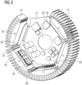
- FIG 2 shows an example arrangement of an overall board with central board 27 and edge boards 26 in one plane.
- a number of power modules are arranged on the central board 27, which are electrically contacted with the power modules arranged on the edge boards 26 via rigid-flex connections in the bending sections 28.
- the central board 27 has a hexagonal basic shape, with one side being free from the edge board 26 in order to enable connection options, for example to a motor and/or terminal box 37.
- connection element 32 is provided to ensure an electrical supply to the drive 1. If all sides of the central board 27 are provided with edge boards 26, an electrical supply can also be provided via a cover 36.
- the ribs 21 and the ribs of the housing 10 of the dynamoelectric rotary machine 2 are in axial alignment in order to offer as little flow resistance as possible to the cooling air flow.
- the drive 1 and its respective sections/parts/components are cooled by one or more cooling units, which can be implemented as liquid cooling (cooling jacket on the housing arrangement 38 and/or on the housing 10 of the dynamoelectric rotary machine 2).
- Air cooling is preferably provided, the fan 15 of which is located on the side of the housing arrangement facing away from the dynamoelectric rotary machine 2, so that there is an axial sequence of fan 15, housing arrangement of the electronic attachment 13 and dynamoelectric rotary machine 2.
- the cylindrical section and/or the axially tapered section has axially or quasi-radially extending ribs on its outer side.
- the inside of the cylindrical section and/or the axially tapered section is polygonal in order to be able to arrange actuator and/or converter components directly on the inside of the housing arrangement 38. This ensures a comparatively good thermal connection.
- the internal fan can either be controlled separately as an external fan depending on the temperature, or is magnetically coupled to the shaft 9, so that a type of self-ventilation of the electronic attachment 13 is present as soon as the shaft 9 rotates.
- the internal fan is driven by a magnetic coupling of magnets positioned on the shaft 9 and correspondingly arranged magnets within the electronic attachment 13, for example on a hub of the internal fan.
- the internal fan can also obtain its drive energy from the rotating field of the dynamoelectric rotary machine 2, in particular its harmonics.
- the drive 1 can also have a control unit that receives data from a wide variety of sensors, including temperature sensors, vibration sensors, sound sensors.
- the temperature sensors in this drive 1 are arranged at the relevant installation locations. Temperature sensors are provided for the outside air, for the electronic attachment 13, the power semiconductor in the electronic attachment 13, for the bearing(s) 11, 12, for the winding system and/or the winding head 4, for the interior of the machine 2, as well as for the housing 10 and the environment.
Landscapes
- Engineering & Computer Science (AREA)
- Microelectronics & Electronic Packaging (AREA)
- Power Engineering (AREA)
- Motor Or Generator Cooling System (AREA)
Claims (12)
- Fabrication d'un convertisseur (13) d'un entraînement ayant des composants d'actionneur et/ou de convertisseur par les stades suivants :- on se procure un agencement, en particulier plan, de plusieurs platines (26, 27), sur chacune desquelles sont prévues des pistes conductrices de l'électricité, qui ont des connexions électriques, une piste (27) centrale ayant une ouverture (29) disposée au milieu afin d'autoriser le passage d'un arbre (9),- on dispose les platines (26, 27) en étoile, en prévoyant la platine (27) centrale et les platines (26) marginales qui l'entourent,- on connecte les platines (26) marginales au moins à la platine (27) centrale par des connexions conductrices de l'électricité,- on équipe les platines (26, 27) de conception plane des composants (30) électriques et/ou électroniques prévus à cet effet,- on contrôle électriquement l'équipement, le câblage, etc.,- on met des segments (31) en matériau bon conducteur de la chaleur sur au moins deux platines de manière à ce que, par une opération de flexion dans la partie d'une connexion électrique entre les platines, les segments forment un recouvrement (20) fermé à peu près périphérique,- on met des couvercles (36) sur les côtés ouverts du recouvrement (20), pour obtenir ainsi un agencement (38) de boîtier fermé.
- Fabrication d'un convertisseur (13) d'un entraînement ayant des composants d'actionneur et/ou de convertisseur suivant la revendication 1, caractérisée en ce que l'on réalise la connexion conductrice de l'électricité sous la forme d'une connexion starflex.
- Fabrication d'un convertisseur (13) d'un entraînement ayant des composants d'actionneur et/ou de convertisseur suivant l'une des revendications précédentes, caractérisée en ce que l'on prévoit des possibilités de connexion radiales et/ou axiales dans le recouvrement (20), en particulier dans un segment (31) et/ou un couvercle (36).
- Fabrication d'un convertisseur (13) d'un entraînement ayant des composants d'actionneur et/ou de convertisseur suivant l'une des revendications précédentes, caractérisée en ce que l'on assemble mécaniquement les uns aux autres les segments (31) par des connecteurs.
- Convertisseur (13) d'un entraînement ayant des composants d'actionneur ou de convertisseur qui sont disposés sur des platines (26, 27), dans lequel les platines (26, 27) sont disposées en étoile, dans lequel le convertisseur (13) a une platine (27) centrale et des platines (26) marginales entourant celles-ci, les platines (26) marginales étant connectées au moins à la platine (27) centrale par des connexions conductrices de l'électricité,dans lequel un recouvrement (20) périphérique est composé d'au moins deux segments (31) qui sont en un matériau bon conducteur de la chaleur,dans lequel chaque segment (31) est en contact conducteur directement de la chaleur avec au moins une platine (26) marginale,dans lequel la platine (27) centrale a une ouverture (29) au milieu, afin de permettre le passage d'un arbre (9),dans lequel les platines (26) marginales et respectivement la platine (27) centrale sont disposées sur une partie (28) de flexion dans la partie des connexions électriques en étant incurvées suivant un angle donné à l'avance.
- Convertisseur (13) d'un entraînement ayant des composants d'actionneur ou de convertisseur suivant la revendication 5, caractérisé en ce que la connexion conductrice de l'électricité entre la platine (26) marginale et la platine (27) centrale est une connexion starflex.
- Convertisseur (13) d'un entraînement ayant des composants d'actionneur ou de convertisseur suivant la revendication 5 ou 6, caractérisé en ce qu'il est prévu, en particulier sur la délimitation extérieure radialement du recouvrement (20), des nervures (21) de refroidissement s'étendant sensiblement axialement.
- Entraînement (1) comprenant- au moins une machine (2) tournante dynamoélectrique,- au moins un convertisseur (13) suivant l'une des revendications 5 à 7,- au moins une unité (15) de refroidissement,- dans lequel ces composants de l'entraînement (1) sont disposés les uns derrière les autres axialement, de manière à ce que la partie (13) électronique rapportée soit disposée axialement entre la machine (2) tournante dynamoélectrique et l'unité (15) de refroidissement,- dans lequel le convertisseur (13) est refroidi par un courant d'air de refroidissement.
- Entraînement (1) suivant la revendication 8, caractérisé en ce que les nervures (21) de refroidissement du recouvrement (20) et des nervures de refroidissement d'une carcasse (10) de la machine tournante dynamoélectrique sont alignées axialement.
- Entraînement (1) suivant la revendication 8 ou 9, caractérisé en ce que l'unité (15) de refroidissement est constituée sous la forme d'une unité de ventilateur, qui produit au moins par endroit, sur le recouvrement (20) et sur la machine (2) tournante dynamoélectrique, un courant d'air de refroidissement, alors que la machine (2) tournante dynamoélectrique est en fonctionnement.
- Entraînement (1) suivant la revendication 10, caractérisé en ce qu'une hotte (16) de ventilateur sert de dispositif de conduite du courant d'air de refroidissement, qui, à partir du côté BS, va jusqu'à environ 30% de la longueur axiale de la carcasse (10) de la machine (2) tournante dynamoélectrique.
- Entraînement (1) suivant l'une des revendications 8 à 11, caractérisé en ce que les couvercles (36) du recouvrement (20) et la partie (13) électronique rapportée ont, dans la partie de l'arbre, un évidement pour rendre possible une ventilation propre de l'entraînement (1).
Applications Claiming Priority (2)
| Application Number | Priority Date | Filing Date | Title |
|---|---|---|---|
| EP19210995.7A EP3826153A1 (fr) | 2019-11-22 | 2019-11-22 | Entraînement pourvu de boîtier de convertisseur segmenté |
| PCT/EP2020/080958 WO2021099121A1 (fr) | 2019-11-22 | 2020-11-04 | Entraînement doté d'un boîtier d'onduleur segmenté |
Publications (3)
| Publication Number | Publication Date |
|---|---|
| EP4010966A1 EP4010966A1 (fr) | 2022-06-15 |
| EP4010966B1 true EP4010966B1 (fr) | 2024-07-10 |
| EP4010966C0 EP4010966C0 (fr) | 2024-07-10 |
Family
ID=68654414
Family Applications (2)
| Application Number | Title | Priority Date | Filing Date |
|---|---|---|---|
| EP19210995.7A Withdrawn EP3826153A1 (fr) | 2019-11-22 | 2019-11-22 | Entraînement pourvu de boîtier de convertisseur segmenté |
| EP20804473.5A Active EP4010966B1 (fr) | 2019-11-22 | 2020-11-04 | Entraînement pourvu de boîtier de convertisseur segmenté |
Family Applications Before (1)
| Application Number | Title | Priority Date | Filing Date |
|---|---|---|---|
| EP19210995.7A Withdrawn EP3826153A1 (fr) | 2019-11-22 | 2019-11-22 | Entraînement pourvu de boîtier de convertisseur segmenté |
Country Status (4)
| Country | Link |
|---|---|
| US (1) | US12445020B2 (fr) |
| EP (2) | EP3826153A1 (fr) |
| CN (1) | CN114731096B (fr) |
| WO (1) | WO2021099121A1 (fr) |
Families Citing this family (3)
| Publication number | Priority date | Publication date | Assignee | Title |
|---|---|---|---|---|
| EP4102694A1 (fr) * | 2021-06-09 | 2022-12-14 | MAHLE International GmbH | Onduleur pour moteur électrique |
| CN119013878A (zh) * | 2022-03-04 | 2024-11-22 | Tvs电机股份有限公司 | 用于电动马达的马达控制单元及其集成的电动马达-马达控制单元组合件 |
| DE102023202803B3 (de) * | 2023-03-28 | 2024-06-27 | Siemens Aktiengesellschaft | Elektronikanordnung |
Family Cites Families (24)
| Publication number | Priority date | Publication date | Assignee | Title |
|---|---|---|---|---|
| DE3842588A1 (de) | 1988-12-17 | 1990-06-21 | Mulfingen Elektrobau Ebm | Kollektorloser aussenlaeufermotor mit halbleiter-kuehlungsanordnung |
| DE3936906C2 (de) | 1989-11-06 | 1995-02-02 | Telefunken Microelectron | Gehäuse für Kfz-Elektronik |
| US5159751A (en) | 1990-02-05 | 1992-11-03 | Motorola, Inc. | Method of manufacturing electronic module assembly |
| DE69222864T2 (de) | 1991-12-02 | 1998-03-26 | Motorola Inc | Elektronische modulare anordnung |
| US5179501A (en) | 1992-02-24 | 1993-01-12 | Motorola, Inc. | Laminated electronic module assembly |
| US5434362A (en) | 1994-09-06 | 1995-07-18 | Motorola, Inc. | Flexible circuit board assembly and method |
| US5998738A (en) | 1996-08-30 | 1999-12-07 | Motorola Inc. | Electronic control module |
| JP3204916B2 (ja) * | 1997-02-28 | 2001-09-04 | 株式会社東芝 | インバータ一体型モータ |
| DE19812729A1 (de) | 1998-03-24 | 1999-09-30 | Bosch Gmbh Robert | Elektromotor, insbesondere mit einem Lüfterrad zur Bildung eines Axial- oder Radiallüfters |
| DE10130950A1 (de) * | 2001-06-27 | 2003-01-23 | Behr Gmbh & Co | Elektromotor |
| US6862191B1 (en) | 2003-08-19 | 2005-03-01 | Cardiac Pacemakers, Inc. | Volumetrically efficient electronic circuit module |
| US6927344B1 (en) | 2004-02-27 | 2005-08-09 | Motorola, Inc. | Flexible circuit board assembly |
| US7394149B2 (en) | 2006-03-08 | 2008-07-01 | Microelectronics Assembly Technologies, Inc. | Thin multichip flex-module |
| DE102009060780A1 (de) * | 2009-12-22 | 2011-06-30 | Automotive Lighting Reutlingen GmbH, 72762 | Elektronisches Steuergerät und Gasentladungslampe für eine Beleuchtungseinrichtung eines Kraftfahrzeugs mit einem solchen Steuergerät |
| DE202010018108U1 (de) * | 2010-06-02 | 2014-05-06 | Ssb Wind Systems Gmbh & Co. Kg | Elektrische Antriebsanordnung |
| US9331544B2 (en) * | 2010-07-14 | 2016-05-03 | Panasonic Intellectual Property Management Co., Ltd. | Brushless motor and method of manufacturing thereof |
| JP5622043B2 (ja) | 2010-09-15 | 2014-11-12 | アイシン・エィ・ダブリュ株式会社 | インバータ装置 |
| US10361603B2 (en) * | 2013-12-16 | 2019-07-23 | Mitsubishi Electric Corporation | Mechanically and electrically integrated driving apparatus and manufacturing method therefor |
| DE112015002495B4 (de) * | 2014-05-28 | 2023-10-05 | Mitsubishi Electric Corporation | Elektrische Energie umwandelnde Vorrichtung |
| TWI576596B (zh) | 2014-11-20 | 2017-04-01 | 力智電子股份有限公司 | 具溫度補償的電量量測裝置及其溫度補償方法 |
| DE102015209543A1 (de) * | 2015-05-22 | 2016-11-24 | Lenze Drives Gmbh | Motorsystem |
| EP3444927B1 (fr) | 2016-04-13 | 2024-04-10 | Kuroda Precision Industries Ltd. | Procédé de fabrication d'un corps d'empliment de tôles comprenant des aimants incorporés |
| DE102018128594A1 (de) * | 2017-11-15 | 2019-05-16 | Steering Solutions Ip Holding Corporation | Halbflexible, gefurchte leiterplattenanordnung |
| US10998797B2 (en) * | 2017-12-19 | 2021-05-04 | Tti (Macao Commercial Offshore) Limited | Electric motor assembly including end cap having heat sink for heat-generating electrical component |
-
2019
- 2019-11-22 EP EP19210995.7A patent/EP3826153A1/fr not_active Withdrawn
-
2020
- 2020-11-04 US US17/773,788 patent/US12445020B2/en active Active
- 2020-11-04 CN CN202080080512.7A patent/CN114731096B/zh active Active
- 2020-11-04 WO PCT/EP2020/080958 patent/WO2021099121A1/fr not_active Ceased
- 2020-11-04 EP EP20804473.5A patent/EP4010966B1/fr active Active
Also Published As
| Publication number | Publication date |
|---|---|
| US20220393557A1 (en) | 2022-12-08 |
| CN114731096A (zh) | 2022-07-08 |
| EP4010966A1 (fr) | 2022-06-15 |
| WO2021099121A1 (fr) | 2021-05-27 |
| EP3826153A1 (fr) | 2021-05-26 |
| CN114731096B (zh) | 2025-09-26 |
| US12445020B2 (en) | 2025-10-14 |
| EP4010966C0 (fr) | 2024-07-10 |
Similar Documents
| Publication | Publication Date | Title |
|---|---|---|
| EP4010966B1 (fr) | Entraînement pourvu de boîtier de convertisseur segmenté | |
| EP2639940B1 (fr) | Moteur électrique | |
| EP0958646B2 (fr) | Moteur electrique a convertisseur de frequence monte en amont | |
| EP3490116B1 (fr) | Actionneur comprenant un commande et moyens de refroidissement | |
| EP2110929B1 (fr) | Convertisseur de fréquence attachée sur un moteur | |
| EP2979347B1 (fr) | Machine électrique pourvue d'un flasque | |
| EP3224931B1 (fr) | Système motorisé | |
| DE112014002106T5 (de) | Elektrische Maschine mit flüssigkeitsgekühltem Gehäuse | |
| DE202015009553U1 (de) | Elektromotor | |
| WO2019154556A1 (fr) | Moteur électrique et procédé de fabrication d'un moteur électrique | |
| EP3719972A1 (fr) | Unité d'entraînement d'une unité de refroidissement | |
| DE102013208226A1 (de) | Kühlelement für einen Radnabenantrieb sowie Radnabenantrieb | |
| WO2020200762A1 (fr) | Unité d'entraînement dotée d'un refroidissement d'arbre | |
| WO2012007194A2 (fr) | Entraînement de réglage du pas d'une pale pour une éolienne | |
| WO2020200763A1 (fr) | Unité d'entraînement dotée d'un refroidissement interne d'un ensemble électronique | |
| WO2020200626A1 (fr) | Unité d'entraînement avec gestion thermique | |
| EP3719968A1 (fr) | Unité d'entraînement pourvue de logement pour une pièce rapportée électronique | |
| EP3719973A1 (fr) | Unité d'entraînement dotée d'une unité d'aérateur | |
| EP3809564B1 (fr) | Entraînement | |
| EP3580838B1 (fr) | Moteur à convertisseur | |
| EP3719969A1 (fr) | Unité d'entraînement dotée d'un système d'aération | |
| DE102019105479A1 (de) | Elektrische Maschine mit integrierter Leistungselektronik | |
| EP4712318A1 (fr) | Convertisseur intégré à un moteur avec élément de blindage | |
| EP4712316A1 (fr) | Convertisseur intégré à un moteur dans un flasque de palier | |
| DE102010064385A1 (de) | Elektrische Maschine |
Legal Events
| Date | Code | Title | Description |
|---|---|---|---|
| STAA | Information on the status of an ep patent application or granted ep patent |
Free format text: STATUS: UNKNOWN |
|
| STAA | Information on the status of an ep patent application or granted ep patent |
Free format text: STATUS: THE INTERNATIONAL PUBLICATION HAS BEEN MADE |
|
| PUAI | Public reference made under article 153(3) epc to a published international application that has entered the european phase |
Free format text: ORIGINAL CODE: 0009012 |
|
| STAA | Information on the status of an ep patent application or granted ep patent |
Free format text: STATUS: REQUEST FOR EXAMINATION WAS MADE |
|
| 17P | Request for examination filed |
Effective date: 20220309 |
|
| AK | Designated contracting states |
Kind code of ref document: A1 Designated state(s): AL AT BE BG CH CY CZ DE DK EE ES FI FR GB GR HR HU IE IS IT LI LT LU LV MC MK MT NL NO PL PT RO RS SE SI SK SM TR |
|
| DAV | Request for validation of the european patent (deleted) | ||
| DAX | Request for extension of the european patent (deleted) | ||
| RAP1 | Party data changed (applicant data changed or rights of an application transferred) |
Owner name: INNOMOTICS GMBH |
|
| GRAP | Despatch of communication of intention to grant a patent |
Free format text: ORIGINAL CODE: EPIDOSNIGR1 |
|
| STAA | Information on the status of an ep patent application or granted ep patent |
Free format text: STATUS: GRANT OF PATENT IS INTENDED |
|
| INTG | Intention to grant announced |
Effective date: 20240315 |
|
| GRAS | Grant fee paid |
Free format text: ORIGINAL CODE: EPIDOSNIGR3 |
|
| GRAA | (expected) grant |
Free format text: ORIGINAL CODE: 0009210 |
|
| STAA | Information on the status of an ep patent application or granted ep patent |
Free format text: STATUS: THE PATENT HAS BEEN GRANTED |
|
| AK | Designated contracting states |
Kind code of ref document: B1 Designated state(s): AL AT BE BG CH CY CZ DE DK EE ES FI FR GB GR HR HU IE IS IT LI LT LU LV MC MK MT NL NO PL PT RO RS SE SI SK SM TR |
|
| REG | Reference to a national code |
Ref country code: CH Ref legal event code: EP |
|
| REG | Reference to a national code |
Ref country code: DE Ref legal event code: R096 Ref document number: 502020008548 Country of ref document: DE |
|
| U01 | Request for unitary effect filed |
Effective date: 20240710 |
|
| U07 | Unitary effect registered |
Designated state(s): AT BE BG DE DK EE FI FR IT LT LU LV MT NL PT RO SE SI Effective date: 20240902 |
|
| U20 | Renewal fee for the european patent with unitary effect paid |
Year of fee payment: 5 Effective date: 20241118 |
|
| PG25 | Lapsed in a contracting state [announced via postgrant information from national office to epo] |
Ref country code: NO Free format text: LAPSE BECAUSE OF FAILURE TO SUBMIT A TRANSLATION OF THE DESCRIPTION OR TO PAY THE FEE WITHIN THE PRESCRIBED TIME-LIMIT Effective date: 20241010 |
|
| PG25 | Lapsed in a contracting state [announced via postgrant information from national office to epo] |
Ref country code: GR Free format text: LAPSE BECAUSE OF FAILURE TO SUBMIT A TRANSLATION OF THE DESCRIPTION OR TO PAY THE FEE WITHIN THE PRESCRIBED TIME-LIMIT Effective date: 20241011 Ref country code: PL Free format text: LAPSE BECAUSE OF FAILURE TO SUBMIT A TRANSLATION OF THE DESCRIPTION OR TO PAY THE FEE WITHIN THE PRESCRIBED TIME-LIMIT Effective date: 20240710 |
|
| PG25 | Lapsed in a contracting state [announced via postgrant information from national office to epo] |
Ref country code: IS Free format text: LAPSE BECAUSE OF FAILURE TO SUBMIT A TRANSLATION OF THE DESCRIPTION OR TO PAY THE FEE WITHIN THE PRESCRIBED TIME-LIMIT Effective date: 20241110 |
|
| PG25 | Lapsed in a contracting state [announced via postgrant information from national office to epo] |
Ref country code: HR Free format text: LAPSE BECAUSE OF FAILURE TO SUBMIT A TRANSLATION OF THE DESCRIPTION OR TO PAY THE FEE WITHIN THE PRESCRIBED TIME-LIMIT Effective date: 20240710 |
|
| PG25 | Lapsed in a contracting state [announced via postgrant information from national office to epo] |
Ref country code: ES Free format text: LAPSE BECAUSE OF FAILURE TO SUBMIT A TRANSLATION OF THE DESCRIPTION OR TO PAY THE FEE WITHIN THE PRESCRIBED TIME-LIMIT Effective date: 20240710 Ref country code: RS Free format text: LAPSE BECAUSE OF FAILURE TO SUBMIT A TRANSLATION OF THE DESCRIPTION OR TO PAY THE FEE WITHIN THE PRESCRIBED TIME-LIMIT Effective date: 20241010 |
|
| PG25 | Lapsed in a contracting state [announced via postgrant information from national office to epo] |
Ref country code: RS Free format text: LAPSE BECAUSE OF FAILURE TO SUBMIT A TRANSLATION OF THE DESCRIPTION OR TO PAY THE FEE WITHIN THE PRESCRIBED TIME-LIMIT Effective date: 20241010 Ref country code: PL Free format text: LAPSE BECAUSE OF FAILURE TO SUBMIT A TRANSLATION OF THE DESCRIPTION OR TO PAY THE FEE WITHIN THE PRESCRIBED TIME-LIMIT Effective date: 20240710 Ref country code: NO Free format text: LAPSE BECAUSE OF FAILURE TO SUBMIT A TRANSLATION OF THE DESCRIPTION OR TO PAY THE FEE WITHIN THE PRESCRIBED TIME-LIMIT Effective date: 20241010 Ref country code: IS Free format text: LAPSE BECAUSE OF FAILURE TO SUBMIT A TRANSLATION OF THE DESCRIPTION OR TO PAY THE FEE WITHIN THE PRESCRIBED TIME-LIMIT Effective date: 20241110 Ref country code: HR Free format text: LAPSE BECAUSE OF FAILURE TO SUBMIT A TRANSLATION OF THE DESCRIPTION OR TO PAY THE FEE WITHIN THE PRESCRIBED TIME-LIMIT Effective date: 20240710 Ref country code: GR Free format text: LAPSE BECAUSE OF FAILURE TO SUBMIT A TRANSLATION OF THE DESCRIPTION OR TO PAY THE FEE WITHIN THE PRESCRIBED TIME-LIMIT Effective date: 20241011 Ref country code: ES Free format text: LAPSE BECAUSE OF FAILURE TO SUBMIT A TRANSLATION OF THE DESCRIPTION OR TO PAY THE FEE WITHIN THE PRESCRIBED TIME-LIMIT Effective date: 20240710 |
|
| PG25 | Lapsed in a contracting state [announced via postgrant information from national office to epo] |
Ref country code: SM Free format text: LAPSE BECAUSE OF FAILURE TO SUBMIT A TRANSLATION OF THE DESCRIPTION OR TO PAY THE FEE WITHIN THE PRESCRIBED TIME-LIMIT Effective date: 20240710 |
|
| PG25 | Lapsed in a contracting state [announced via postgrant information from national office to epo] |
Ref country code: CZ Free format text: LAPSE BECAUSE OF FAILURE TO SUBMIT A TRANSLATION OF THE DESCRIPTION OR TO PAY THE FEE WITHIN THE PRESCRIBED TIME-LIMIT Effective date: 20240710 |
|
| PG25 | Lapsed in a contracting state [announced via postgrant information from national office to epo] |
Ref country code: SK Free format text: LAPSE BECAUSE OF FAILURE TO SUBMIT A TRANSLATION OF THE DESCRIPTION OR TO PAY THE FEE WITHIN THE PRESCRIBED TIME-LIMIT Effective date: 20240710 |
|
| U1N | Appointed representative for the unitary patent procedure changed after the registration of the unitary effect |
Representative=s name: MICHALSKI HUETTERMANN & PARTNERPATENTANWAELTE MBB; DE |
|
| PLBE | No opposition filed within time limit |
Free format text: ORIGINAL CODE: 0009261 |
|
| STAA | Information on the status of an ep patent application or granted ep patent |
Free format text: STATUS: NO OPPOSITION FILED WITHIN TIME LIMIT |
|
| 26N | No opposition filed |
Effective date: 20250411 |
|
| REG | Reference to a national code |
Ref country code: CH Ref legal event code: PL |
|
| PG25 | Lapsed in a contracting state [announced via postgrant information from national office to epo] |
Ref country code: MC Free format text: LAPSE BECAUSE OF FAILURE TO SUBMIT A TRANSLATION OF THE DESCRIPTION OR TO PAY THE FEE WITHIN THE PRESCRIBED TIME-LIMIT Effective date: 20240710 |
|
| REG | Reference to a national code |
Ref country code: CH Ref legal event code: PL |
|
| GBPC | Gb: european patent ceased through non-payment of renewal fee |
Effective date: 20241104 |
|
| PG25 | Lapsed in a contracting state [announced via postgrant information from national office to epo] |
Ref country code: CH Free format text: LAPSE BECAUSE OF NON-PAYMENT OF DUE FEES Effective date: 20241130 |
|
| PG25 | Lapsed in a contracting state [announced via postgrant information from national office to epo] |
Ref country code: GB Free format text: LAPSE BECAUSE OF NON-PAYMENT OF DUE FEES Effective date: 20241104 |
|
| PG25 | Lapsed in a contracting state [announced via postgrant information from national office to epo] |
Ref country code: IE Free format text: LAPSE BECAUSE OF NON-PAYMENT OF DUE FEES Effective date: 20241104 |
|
| U20 | Renewal fee for the european patent with unitary effect paid |
Year of fee payment: 6 Effective date: 20251119 |
|
| PG25 | Lapsed in a contracting state [announced via postgrant information from national office to epo] |
Ref country code: HU Free format text: LAPSE BECAUSE OF FAILURE TO SUBMIT A TRANSLATION OF THE DESCRIPTION OR TO PAY THE FEE WITHIN THE PRESCRIBED TIME-LIMIT; INVALID AB INITIO Effective date: 20201104 |
|
| PG25 | Lapsed in a contracting state [announced via postgrant information from national office to epo] |
Ref country code: CY Free format text: LAPSE BECAUSE OF FAILURE TO SUBMIT A TRANSLATION OF THE DESCRIPTION OR TO PAY THE FEE WITHIN THE PRESCRIBED TIME-LIMIT; INVALID AB INITIO Effective date: 20201104 |