EP4011248A1 - Support décoratif pour plateaux, boîtes et casseroles de produits alimentaires - Google Patents
Support décoratif pour plateaux, boîtes et casseroles de produits alimentaires Download PDFInfo
- Publication number
- EP4011248A1 EP4011248A1 EP21210438.4A EP21210438A EP4011248A1 EP 4011248 A1 EP4011248 A1 EP 4011248A1 EP 21210438 A EP21210438 A EP 21210438A EP 4011248 A1 EP4011248 A1 EP 4011248A1
- Authority
- EP
- European Patent Office
- Prior art keywords
- receptacle
- lid
- decorative holder
- foodstuff
- recesses
- Prior art date
- Legal status (The legal status is an assumption and is not a legal conclusion. Google has not performed a legal analysis and makes no representation as to the accuracy of the status listed.)
- Pending
Links
Images












Classifications
-
- A—HUMAN NECESSITIES
- A47—FURNITURE; DOMESTIC ARTICLES OR APPLIANCES; COFFEE MILLS; SPICE MILLS; SUCTION CLEANERS IN GENERAL
- A47J—KITCHEN EQUIPMENT; COFFEE MILLS; SPICE MILLS; APPARATUS FOR MAKING BEVERAGES
- A47J36/00—Parts, details or accessories of cooking-vessels
- A47J36/34—Supports for cooking-vessels
-
- A—HUMAN NECESSITIES
- A47—FURNITURE; DOMESTIC ARTICLES OR APPLIANCES; COFFEE MILLS; SPICE MILLS; SUCTION CLEANERS IN GENERAL
- A47J—KITCHEN EQUIPMENT; COFFEE MILLS; SPICE MILLS; APPARATUS FOR MAKING BEVERAGES
- A47J47/00—Kitchen containers, stands or the like, not provided for in other groups of this subclass; Cutting-boards, e.g. for bread
- A47J47/16—Stands, or holders for kitchen articles
-
- B—PERFORMING OPERATIONS; TRANSPORTING
- B65—CONVEYING; PACKING; STORING; HANDLING THIN OR FILAMENTARY MATERIAL
- B65D—CONTAINERS FOR STORAGE OR TRANSPORT OF ARTICLES OR MATERIALS, e.g. BAGS, BARRELS, BOTTLES, BOXES, CANS, CARTONS, CRATES, DRUMS, JARS, TANKS, HOPPERS, FORWARDING CONTAINERS; ACCESSORIES, CLOSURES, OR FITTINGS THEREFOR; PACKAGING ELEMENTS; PACKAGES
- B65D25/00—Details of other kinds or types of rigid or semi-rigid containers
- B65D25/02—Internal fittings
-
- A—HUMAN NECESSITIES
- A47—FURNITURE; DOMESTIC ARTICLES OR APPLIANCES; COFFEE MILLS; SPICE MILLS; SUCTION CLEANERS IN GENERAL
- A47G—HOUSEHOLD OR TABLE EQUIPMENT
- A47G19/00—Table service
- A47G19/02—Plates, dishes or the like
- A47G19/08—Plate-holders
-
- A—HUMAN NECESSITIES
- A47—FURNITURE; DOMESTIC ARTICLES OR APPLIANCES; COFFEE MILLS; SPICE MILLS; SUCTION CLEANERS IN GENERAL
- A47G—HOUSEHOLD OR TABLE EQUIPMENT
- A47G19/00—Table service
- A47G19/12—Vessels or pots for table use
-
- A—HUMAN NECESSITIES
- A47—FURNITURE; DOMESTIC ARTICLES OR APPLIANCES; COFFEE MILLS; SPICE MILLS; SUCTION CLEANERS IN GENERAL
- A47G—HOUSEHOLD OR TABLE EQUIPMENT
- A47G23/00—Other table equipment
- A47G23/04—Containers with means for keeping food cool or hot
-
- A—HUMAN NECESSITIES
- A47—FURNITURE; DOMESTIC ARTICLES OR APPLIANCES; COFFEE MILLS; SPICE MILLS; SUCTION CLEANERS IN GENERAL
- A47J—KITCHEN EQUIPMENT; COFFEE MILLS; SPICE MILLS; APPARATUS FOR MAKING BEVERAGES
- A47J39/00—Heat-insulated warming chambers; Cupboards with heating arrangements for warming kitchen utensils
- A47J39/006—Heat-insulated warming chambers; Cupboards with heating arrangements for warming kitchen utensils for either storing and preparing or for preparing food on serving trays, e.g. heating, thawing, preserving
-
- A—HUMAN NECESSITIES
- A47—FURNITURE; DOMESTIC ARTICLES OR APPLIANCES; COFFEE MILLS; SPICE MILLS; SUCTION CLEANERS IN GENERAL
- A47J—KITCHEN EQUIPMENT; COFFEE MILLS; SPICE MILLS; APPARATUS FOR MAKING BEVERAGES
- A47J47/00—Kitchen containers, stands or the like, not provided for in other groups of this subclass; Cutting-boards, e.g. for bread
- A47J47/14—Carriers for prepared human food
-
- B—PERFORMING OPERATIONS; TRANSPORTING
- B65—CONVEYING; PACKING; STORING; HANDLING THIN OR FILAMENTARY MATERIAL
- B65D—CONTAINERS FOR STORAGE OR TRANSPORT OF ARTICLES OR MATERIALS, e.g. BAGS, BARRELS, BOTTLES, BOXES, CANS, CARTONS, CRATES, DRUMS, JARS, TANKS, HOPPERS, FORWARDING CONTAINERS; ACCESSORIES, CLOSURES, OR FITTINGS THEREFOR; PACKAGING ELEMENTS; PACKAGES
- B65D25/00—Details of other kinds or types of rigid or semi-rigid containers
- B65D25/28—Handles
- B65D25/30—Hand holes
-
- B—PERFORMING OPERATIONS; TRANSPORTING
- B65—CONVEYING; PACKING; STORING; HANDLING THIN OR FILAMENTARY MATERIAL
- B65D—CONTAINERS FOR STORAGE OR TRANSPORT OF ARTICLES OR MATERIALS, e.g. BAGS, BARRELS, BOTTLES, BOXES, CANS, CARTONS, CRATES, DRUMS, JARS, TANKS, HOPPERS, FORWARDING CONTAINERS; ACCESSORIES, CLOSURES, OR FITTINGS THEREFOR; PACKAGING ELEMENTS; PACKAGES
- B65D43/00—Lids or covers for rigid or semi-rigid containers
- B65D43/14—Non-removable lids or covers
- B65D43/16—Non-removable lids or covers hinged for upward or downward movement
- B65D43/163—Non-removable lids or covers hinged for upward or downward movement the container and the lid being made separately
- B65D43/164—Non-removable lids or covers hinged for upward or downward movement the container and the lid being made separately and connected by interfitting hinge elements integrally with the container and the lid formed respectively
-
- B—PERFORMING OPERATIONS; TRANSPORTING
- B65—CONVEYING; PACKING; STORING; HANDLING THIN OR FILAMENTARY MATERIAL
- B65D—CONTAINERS FOR STORAGE OR TRANSPORT OF ARTICLES OR MATERIALS, e.g. BAGS, BARRELS, BOTTLES, BOXES, CANS, CARTONS, CRATES, DRUMS, JARS, TANKS, HOPPERS, FORWARDING CONTAINERS; ACCESSORIES, CLOSURES, OR FITTINGS THEREFOR; PACKAGING ELEMENTS; PACKAGES
- B65D55/00—Accessories for container closures not otherwise provided for
- B65D55/02—Locking devices; Means for discouraging or indicating unauthorised opening or removal of closure
-
- B—PERFORMING OPERATIONS; TRANSPORTING
- B65—CONVEYING; PACKING; STORING; HANDLING THIN OR FILAMENTARY MATERIAL
- B65D—CONTAINERS FOR STORAGE OR TRANSPORT OF ARTICLES OR MATERIALS, e.g. BAGS, BARRELS, BOTTLES, BOXES, CANS, CARTONS, CRATES, DRUMS, JARS, TANKS, HOPPERS, FORWARDING CONTAINERS; ACCESSORIES, CLOSURES, OR FITTINGS THEREFOR; PACKAGING ELEMENTS; PACKAGES
- B65D43/00—Lids or covers for rigid or semi-rigid containers
- B65D43/14—Non-removable lids or covers
- B65D43/22—Devices for holding in closed position, e.g. clips
-
- B—PERFORMING OPERATIONS; TRANSPORTING
- B65—CONVEYING; PACKING; STORING; HANDLING THIN OR FILAMENTARY MATERIAL
- B65D—CONTAINERS FOR STORAGE OR TRANSPORT OF ARTICLES OR MATERIALS, e.g. BAGS, BARRELS, BOTTLES, BOXES, CANS, CARTONS, CRATES, DRUMS, JARS, TANKS, HOPPERS, FORWARDING CONTAINERS; ACCESSORIES, CLOSURES, OR FITTINGS THEREFOR; PACKAGING ELEMENTS; PACKAGES
- B65D85/00—Containers, packaging elements or packages, specially adapted for particular articles or materials
- B65D85/30—Containers, packaging elements or packages, specially adapted for particular articles or materials for articles particularly sensitive to damage by shock or pressure
- B65D85/36—Containers, packaging elements or packages, specially adapted for particular articles or materials for articles particularly sensitive to damage by shock or pressure for bakery products, e.g. biscuits
Definitions
- the present disclosure relates generally to the field of baking and serving containers. More specifically, the present disclosure relates to decorative and protective holders for cookware and foodstuff trays.
- U.S. Patent Publication No. 2016/0249768 discloses a decorative holder for serving/catering trays and tins that includes a bottom holder/receptacle which receives a traditional foil serving tin, effectively surrounding the bottom and four sides of the serving tin.
- a lid is placed over the upper peripheral edges of the holder/receptacle to hold the serving tin in place and also to cover the upper edges of the serving or catering tin.
- An optional spacer block may be utilized between the bottom of the holder/receptacle and the serving tin so as to align the upper edges of each.
- a decorative holder for foodstuff trays, tins, and pans includes a receptacle having a partially corrugated bottom wall, a pair of opposing side walls, and a pair of opposing end walls. The side walls and the end walls extend upwardly from an outer periphery of the partially corrugated bottom wall and terminate in a top edge.
- the decorative holder further includes a lid that is hingably coupled to the top edge of the receptacle and configured to pivot between an opened position and a closed position, the lid defining a central opening providing access to an interior region of the decorative holder when disposed atop the receptacle.
- the receptacle and the lid are configured to hold and generally encapsulate a foodstuff tray, tin, or pan therebetween.
- a decorative holder for foodstuff trays, tins, and pans.
- the decorative holder includes a receptacle having a bottom wall, a pair of opposing side walls, and a pair of opposing end walls. The side walls and the end walls extend upwardly from an outer periphery of the bottom wall and terminate in a top edge.
- the decorative holder further includes a lid that is hingably coupled to the top edge of the receptacle and configured to pivot between an opened position and a closed position, the lid defining a central opening providing access to an interior region of the decorative holder when disposed atop the receptacle.
- the receptacle and the lid are configured to hold and generally encapsulate a foodstuff tray, tin, or pan therebetween.
- the receptacle further comprises a pair of handle recesses formed therein, the pair of handle recesses extending into the interior region of the decorative holder.
- a decorative holder for foodstuff trays, tins, and pans.
- the decorative holder includes a receptacle having a bottom wall, a pair of opposing side walls, and a pair of opposing end walls. The side walls and the end walls extend upwardly from an outer periphery of the bottom wall and terminate in a top edge.
- the decorative holder further includes a lid that is hingably coupled to the top edge of the receptacle using multiple living hinge clips, The lid is configured to pivot between an opened position and a closed position and the lid defines a central opening providing access to an interior region of the decorative holder when disposed atop the receptacle.
- the receptacle and the lid are configured to hold and generally encapsulate one or more foodstuff trays, tins, or pans therebetween.
- One of the pair of opposing side walls further comprises multiple hinge clip recesses that extend into the interior region of the decorative holder and are configured to couple to the living hinge clips such that the living hinge clips fit over at least a portion of the top edge.
- FIGS. 1 and 2 depict perspective views of a decorative holder assembly 10 in accordance with an exemplary preferred implementation of the present disclosure.
- the decorative holder assembly 10 includes a receptacle 12 and a lid assembly 14 that is detachably coupled to the receptacle 12.
- the lid assembly 14 includes a lid 16 and a cover 18.
- the cover 18 is detachably coupled to the lid 16 using a snap fit assembly process.
- the cover 18 can be coupled and decoupled from the lid 16 to block or permit access to a central opening 54 formed between the receptacle 12 and the lid assembly 14.
- the receptacle 12 is shown to include a pair of opposing side walls 22 and a pair of opposing end walls 24. Each of the side walls 22 and end walls 24 extends upwardly from a bottom wall 60 of the receptacle 12. Further details of the features of the bottom wall 60 are included below with reference to FIGS. 3, 4 , and 6-8 .
- a length 62 of the side walls 22 exceeds a length 64 of the end walls 24 such that the receptacle 12 has a generally rectangular shape.
- the lengths 62, 64 of the side walls 22 and end walls 24 may be identical such that the receptacle 12 has a square shape.
- the lid assembly 14 is hingably coupled to the receptacle 12 such that the lid assembly 14 is pivotable between a closed position (depicted in FIG. 1 ) and an opened position (depicted in FIG. 2 ). Further details regarding the hinge features of the lid 16 and the coupling of the lid assembly 14 and the receptacle 12 are included below with reference to FIGS. 11 and 12 .
- a user may grip a latch extension portion 28 incorporated into the lid 16, unseating one or more latch protrusions 30 formed on the underside of the latch extension portion 28 from a mated position within one or more latch recesses 32 formed in one of the side walls 22 of the receptacle 12. Once the latch protrusions 30 have been unseated from the latch recesses 32, the user may rotate the lid assembly 14 upwardly, exposing the central opening 54.
- the latch extension portion 28 may be branded with a logo or other decorative features.
- a pan 20 is shown to be encapsulated between the receptacle 12 and the lid assembly 14 within the central opening 54.
- the pan 20 is a disposable foil pan used for cooking, transporting, and serving a foodstuff.
- disposable foil pans are flimsy and susceptible to damage during transport.
- foil pans are unattractive and may cause a food served from a foil pan to be less appetizing than a food served from a more attractive vessel. Accordingly, the present inventors have provided a sturdy and attractive decorative holder assembly that remedies these problems as well as additional problems described below.
- pan 20 is shown to include a bottom wall 36, with a pair of opposing pan side walls 38 and a pair of opposing pan end walls 40 extending upwardly therefrom.
- the pan side walls and end walls 38, 40 may terminate in a continuous outwardly extending lip 42.
- the dimensions of the pan 20 may generally conform to a 9 inch wide by 13 inch long cooking pan standard, with a pan height 44 extending from the bottom wall 36 to the lip 42 of approximately 1.5 to 2.5 inches.
- a differently sized pan 20 may be utilized (e.g., an 8 inch by 8 inch pan, a 9 inch by 9 inch pan).
- a rigid non-disposable foodstuff pan 20 may be utilized instead of a disposable foil pan.
- a foodstuff tray e.g., foodstuff tray 302, depicted in FIG. 18
- An example of the decorative holder assembly 10 in a food tray configuration is described below with reference to FIG. 17 .
- the receptacle 12 is further shown to include a handle recess 26 formed in each of the receptacle end walls 24.
- the handle recesses 26 permit a user to insert their fingers within the recesses 26 on the decorative holder assembly 10 for transport purposes.
- the handle recesses 26 extend inwardly into the central opening 54, thus providing the receptacle 12 with an attractive and sleek appearance not achievable through outwardly extending handles.
- Each handle recess 26 is defined by an upwardly extending and outwardly sloping handle wall portion 66 as well as a grip wall portion 68 that slopes downwardly from the handle wall portion 66 and terminates in an outer lip 70.
- the dimensions of the wall portions 66, 68 and the outer lip 70 may vary to form larger or smaller recesses 26, or the recesses 26 may be formed in a different location on the receptacle 12 (e.g., the side walls 22).
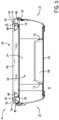
- the handle wall portion 66 slopes outwardly from the bottom wall 60 and generally matches the profile of the end walls 40 of the pan 20 such that the pan 20 rests against the handle wall portions 66 (depicted in FIG. 3 ). By matching the profile of the handle wall portion 66 to the end walls 40, lateral movement of the pan 20 relative to the receptacle 12 is prevented and a risk of spillage of food contained within the pan 20 during transport of the decorative holder assembly 10 is minimized.
- each handle recess 26 is bound by inwardly sloping handle end wall portions 72.
- the end wall portions 72 may be inclined, that is, non-orthogonal to the bottom wall 60 of the receptacle 12. By utilizing non-orthogonal orientations for the handle wall and end wall portions 66, 72, easier fabrication of the receptacle 12 is achieved.
- the handle recesses 26 are not bound by the end wall portions 72, and the recesses 26 may extend the entire length 64 (see FIG. 2 ) of the end walls 24.
- both the receptacle 12 and the lid 16 are fabricated from polypropylene, while the cover 18 is fabricated from transparent styrene-acrylonitrile resin (SAN).
- SAN transparent styrene-acrylonitrile resin
- each of the receptacle 12, lid 16, and cover 18 may be fabricated from polymethyl methacrylate (PMMA), polyethylene terephthalate (PET), polycarbonate (PC), clarified polypropylene (PP), Plexiglass, Tritan, Kostrate Edge, EdgeGlass, or an alloy blend of various polymer materials. The material may be selected based on the intended use of the decorative holder assembly 10.
- PC or Tritan may be selected for their low temperature resiliency and crack resistance if the decorative holder assembly 10 is expected to be subjected to freezing temperatures or high drop impacts.
- Each of the receptacle 12, lid 16, and cover 18 may be fabricated using an injection molding process. The present inventors have recognized that injection molding results in a high quality detailed part at a low cost per part. In other implementations, a different fabrication process may be utilized, including, but not limited to, vacuum forming, blow molding, and rapid production.
- an additional configuration of the decorative holder assembly 10 is shown to include a cooling pack component 56 disposed between the bottom wall 60 of the receptacle 12 and the bottom wall 36 of the pan 20.
- the cooling pack component 56 may be any suitable type of rigid or flexible ice or gel cooling pack that acts to cool the bottom wall 36 of the pan 20 and keep the food contained therein at an optimal temperature for food safety and palatability.
- portions of the cooling pack component 56 may extend upwardly along one or both of the receptacle side walls and end walls 22, 24 to cool one or both of the pan side walls and end walls 38, 40.
- a height 58 of the cooling pack component 56 may be controlled in conjunction with the pan height 44 to ensure that adequate clearance is maintained between the outwardly extending lip 42 of the pan 20 and the lid assembly 14.
- a heating pack component may be utilized in place of the cooling pack component 56, again with the goal of maintaining the food contained in the pan 20 within an optimal temperature range.
- the cover 18 of the lid assembly 14 is shown to include a generally planar central wall 46 having a surface area that generally corresponds to the surface area of the central opening 54 defined by the lid 16.
- the central wall 46 is surrounded by a downwardly sloping peripheral wall 48, an upwardly sloping peripheral wall 50, and a horizontal lip 52.
- the upwardly sloping peripheral wall 50 and the horizontal lip 52 are shown to rest against an outer surface 74 of the lid 16.
- the outer surface 74 of the lid 16 is generally semi-circular and extends from an inner peripheral edge 76 to an outer peripheral edge 78.
- the inner peripheral edge 76 resides within the central opening 54, and the outer peripheral edge 78 is positioned over exterior surfaces of the side walls 22 and end walls 24 of the receptacle 12 and vertically below a peripheral top edge 80 of the receptacle 12.
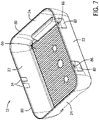
- FIGS. 6-8 The features of the receptacle 12 are further depicted in FIGS. 6-8 . Specifically, FIGS. 6 and 7 respectively depict front and rear perspective views of the receptacle 12, while FIG. 8 depicts a top view of the receptacle 12.
- the receptacle 12 includes a pair of opposing side walls 22 and a pair of opposing end walls 24. Each of the side walls 22 and end walls 24 extends upwardly from a periphery of the bottom wall 60, terminating in the top receptacle edge 80.
- the side walls 22 and edge walls 24 terminate in the top receptacle edge 80 without the inclusion of any horizontally-extending lip, thus providing the receptacle 12 with a sleek, attractive appearance that permits easy coupling of receptacle 12 to the lid assembly 14.
- one of the side walls 22 is shown to include multiple latch recesses 32 that are sized and shaped to receive the latch protrusions 30 extending from the latch extension portion 28 of the lid 16 (also depicted in FIG. 10 , described below). Mating of the latch protrusions 30 to the latch recesses 32 retains the lid assembly 14 in the closed position.
- the latch recesses 32 are positioned just below the top receptacle edge 80, and below one or more latch indicator recesses 34 positioned coincident with the top receptacle edge 80.
- the latch indicator recesses 34 may act as lead-in features that align the latch protrusions 30 for mating with the latch recesses 32.
- an audible indicator e.g., a clicking noise
- an audible indicator may be emitted due to the interaction of the latch protrusions 30 and the latch indicator recesses 34, signaling the achievement of a successful mate to a user.
- the receptacle 12 is shown to include a pair of hinge clip receiving recesses 82 on the sidewall 22 opposing the latch recesses 32 and latch indicator recesses 34.
- Each hinge clip receiving recess 82 is sized and shaped to couple to a living hinge clip 84 extending from the lid 16 (depicted in FIGS. 11 and 12 , described below).
- each of the hinge clip receiving recesses 82 further includes a clip indicator recess or notch 86.
- the clip indicator recess 86 may aid in locating the living hinge clip 84 relative to the hinge clip receiving recess 82, as well as provide audible indication of successful mating between the living hinge clip 84 and the clip receiving recess 82.
- the decorative holder assembly 10 may include a different number of hingable couplings between the hinge clips 84 and clip receiving recesses 82.
- the lid 16 may include only a single hinge clip 84 with a single clip receiving recess 82 on the receptacle 12. Conversely, if the decorative holder assembly 10 is sized to accommodate a large form factor pan 20, the lid 16 may include three or more hinge clips 84 with three or more clip receiving recesses 82 on the receptacle 12.
- the bottom wall 60 includes multiple protrusions 88 that result in the bottom wall 60 being generally corrugated or otherwise non-planar.
- the present inventors have recognized that providing the bottom wall 60 with a corrugated or wave-like surface increases the amount of air permitted to flow underneath the bottom wall 60 when the decorative holder assembly 10 rests on a surface.
- increasing the amount of airflow underneath the bottom wall 60 insulates and aids in cooling of the foodstuff within the pan 20, particularly when the pan 20 is positioned atop an ice pack 56, as depicted in FIG. 4 .
- the corrugated surface has a pattern of high portions and low portions, and in the depicted example is a wave-like pattern that has channels extending a cross-sectional length or width of the pan 20 or tray in the receptacle 12, thereby allowing air to flow and circulate around and under the pan 20 or tray within the receptacle 12.
- the pattern of high and low portions also minimizes the surface area of the bottom wall 60 in contact with the pan 20 or the cooling pack component 56, as well as the surface area of the bottom wall 60 in contact with a tabletop or other surface on which the decorative holder assembly 10 may be disposed. This minimization of surface area reduces the heat transfer between the pan 20 and the bottom wall 60, and the bottom wall 60 and the tabletop.
- the corrugated pattern of the bottom wall 60 may be interrupted by one or more flat surfaces (e.g., circular flat surfaces) that aid in the injection molding process.
- the flat surfaces may correspond to injection molding gate locations, or lift attachment points that permit the receptacle 12 to lifted out of an injection mold cavity using air poppet valves.
- the receptacle 12 is further shown to include tray locating recesses 108 formed in each of the corners of the bottom wall 60.
- the tray locating recesses 108 may be configured to mate with features of a foodstuff tray (e.g., foodstuff tray 302, depicted in FIGS. 17 and 18 ).
- the lid generally consists of an outer surface 74 that extends from an inner peripheral edge 76 to an outer peripheral edge 78.
- the outer peripheral edge 78 is configured to fit over the top edge 80 of the receptacle 12.
- latch protrusions 30 located on a latch extension portion 28 are positioned opposite the pair of living hinge clips 84.
- An inner surface 90 of the lid 16 is also shown to include an inner lip 92 extending at least partially around the inner surface 90 between the inner peripheral edge 76 and the outer peripheral edge 78.
- the inner lip 92 may reside just inside the top edge 80 of the receptacle 12, such that the outer peripheral edge 78 and the inner lip 92 form a clip-like mate over the top edge 80 (see FIGS. 3 and 4 ) of the receptacle 12, thereby minimizing any potential movement of the lid assembly 14 relative to the receptacle 12.
- the inner lip 92 is positioned outwardly of the pan lip 42.
- the inner lip 92 may instead be positioned closer to the inner peripheral edge 76 such that the inner lip 92 is positioned inwardly of the pan lip 42 and acts to retain the pan 20.
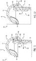
- FIGS. 11 and 12 side cross-sectional views of coupling of the lid 16 and receptacle 12 are depicted.
- the lid 16 includes the living hinge clip 84 extending from the outer peripheral edge 78.
- use of living hinges permits the lid 16 to be fabricated as a single component, thereby simplifying the bill of materials and assembly of the decorative holder assembly 10.
- a living hinge portion 94 of the clip 84 permits the lid assembly 14 to pivot between the closed position and the opened position.
- each clip 84 Adjacent the living hinge portion 94, each clip 84 includes an exterior clip portion 96 and an interior clip portion 98. Together, the exterior clip portion 96 and the interior clip portion 98 are generally C-shaped to fit over the top edge 80 and into a clip receiving recess 82 formed in the sidewall 22 of the receptacle 12.
- the exterior clip portion 96 includes a locating protrusion 100 that extends from the exterior clip portion 96 and is configured to fit within the clip indicator recess 86 formed within the receptacle 12. Mating of the locating protrusion 100 with the clip indicator recess 86 may result in an audible indicator (e.g., a clicking or snapping sound) of a successful coupling of the lid 16 to the receptacle 12.
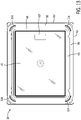
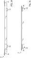
- FIGS. 13-15 respectively depict additional top, front, and side views of the cover 18.
- the cover 18 may include a central wall 46 surrounded by a downwardly sloping peripheral wall 48, an upwardly sloping peripheral wall 50, and a horizontal lip 52.
- the central wall 46 includes a defined branding area 102 in which a logo may be formed (e.g., as part of an injection molding process) or affixed (e.g., using a decal).
- all or a substantial portion of the central wall 46 can be painted, printed or otherwise decorated to provide an attractive appearance to the decorative holder assembly 10.
- the cover 18 is further shown to include stacking protrusions 104 extending inwardly from the upwardly sloping peripheral wall 50, just below the horizontal lip 52.
- the stacking protrusions 104 may be configured to fit with corresponding features (e.g., interlocking protrusions, recesses) located on the exterior surface of the bottom wall 60 of the receptacle 12 in order to limit relative movement of the receptacle 12 and the cover 18.
- the cover 18 may be removed from the lid assembly 14 and placed underneath the receptacle 12 in order to provide access to an interior region within the central opening 54 while serving the foodstuff contained within the pan 20.
- multiple decorative holder assemblies 10 may be stacked atop each other during transport.
- the stacking protrusions 104 are generally arc-shaped, although any desired shape compatible with corresponding features of the receptacle 12 may be utilized.
- the cover 18 also includes detent prongs or tabs 106 extending outwardly from the upwardly sloping peripheral wall 50.
- the detent prongs 106 are configured to fit beneath the inner peripheral edge 76 of the lid 16 (depicted in FIG. 5 ) and act to retain the cover 18 when the cover 18 is coupled to the lid 16 to form the lid assembly 14.
- the cover 18 when assembled in the lid assembly 14, the cover 18 includes one pair of detent prongs 106 extending toward a sidewall 22 of the receptacle 12 and an opposing pair of detent prongs 106 facing the opposite sidewall 22.
- the cover 18 may include a different number of detent prongs 106, in different locations than those depicted in FIGS. 13-15 .
- FIG. 16 depicts multiple decorative holder assemblies in a stacked configuration 200, with an upper decorative holder assembly 202 disposed atop a lower decorative holder assembly 204.
- Each of the upper and lower decorative holder assemblies 202, 204 may be identical or substantially similar to the decorative holder assembly 10 depicted and described above with reference to FIGS. 1-15 .
- the present inventors have recognized that transport of aluminum pans 20 to potlucks, events, or the like often involves the need to transport multiple foodstuff pans 20 at once. Accordingly, the bottom wall 60 of the receptacle 12 on the upper decorative holder assembly 202 is configured to fit with the cover 18 of the lower decorative holder assembly 204 to minimize slip between the assemblies 202, 204 and prevent spillage of foodstuff contained therein.
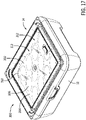
- FIG. 17 depicts a decorative holder assembly 300 in a foodstuff tray configuration.
- Certain components of the decorative holder assembly 300 may be identical or substantially similar to the components of the decorative holder assembly 10, depicted and described above with reference to FIGS. 1-15 .
- the receptacle 12 and the lid assembly 14 may be identical in both the decorative holder assemblies 10 and 200.
- the decorative holder assembly 300 may include a foodstuff tray 302 encapsulated between the receptacle 12 and the lid assembly 14.
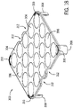
- FIG. 18 depicts a perspective view of the foodstuff tray 302.
- the foodstuff tray 302 includes a generally planar supporting wall 304 with multiple foodstuff indentations 306 formed therein.
- the supporting wall 304 may substantially correspond to the size and shape (e.g., generally rectangular, generally square) of the receptacle 12.
- the indentations 306 may be formed in a regular pattern in the supporting wall 304 such that food items placed within the indentations 306 are separated from each other and aesthetic damage to the foods items is prevented during transport and serving of the food items.
- the indentations 306 may have any other shape required to support a desired food item (e.g., circular shapes suitable for supporting cupcakes).
- the supporting wall 304 may be formed with multiple holes of any desired shape suitable to receive and support a desired food item.
- the foodstuff tray 302 includes four legs 308, with one leg 308 positioned at each of the corners of the supporting wall 304. In other implementations, the foodstuff tray 302 may include a greater or fewer number of legs 308, or legs 308 positioned differently relative to the supporting wall 304.
- the height of each of the legs 308 may correspond to the food items intended to be supported by the indentations 306, as well as the intended purpose of the decorative holder assembly 300. For example, if the legs 308 are too long, there may be insufficient clearance for the food items when the lid assembly 14 is pivoted to a closed position, as depicted in FIG. 17 .
- Each of the legs 308 may be generally arc-shaped, corresponding to arc-shaped corner recesses 310 formed in the supporting wall 304, as well as the tray locating recesses 108 formed in the receptacle 12 (depicted in FIG. 8 ).
- the corner recesses 310 may permit multiple foodstuff trays 302 to be stacked atop each other and encapsulated within the receptacle 12 and lid assembly 14.
- the supporting wall 304 is further shown to include grab recesses 312 formed therein.
- the supporting wall 304 includes a pair of opposing grab recesses 312 facing the side walls 22 of the receptacle 12, although in other implementations, the grab recesses 312 may face the end walls 24 of the receptacle 12.
- the grab recesses 312 may be any shape or size required to permit a user to insert their fingers within the grab recesses 312 and underneath the supporting 304 without damaging the food items placed within the indentations 306.
- the foodstuff tray 302 may be fabricated from any material suitable for the food items intended to be supported by the foodstuff tray 302.
- the foodstuff tray 302 is fabricated from the same material at the receptacle 12 and the lid 16 (e.g., polypropylene).
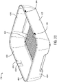
- FIGS. 19 and 20 perspective views of an alternate receptacle 400 are depicted.
- the receptacle 400 is shown to include a pair of opposing side walls 422 and a pair of opposing end walls 424.
- Each of the side walls 422 and the end walls 424 extends upwardly from a periphery of a corrugated bottom wall 460, terminating in a top receptacle edge 480.
- One of the sidewalls 422 is shown to include multiple latch recesses 432 that are situated below latch indicator recesses 434.
- the receptacle 400 is shown to include a pair of internal clip indexing features 482. Referring specifically to FIG. 20 , the side wall 422 opposite the recesses 432, 444 is further shown to include a pair of external detent ribs 486.
- each of the clip indexing features 482 is generally U-shaped and extends from the side wall 422.
- the clip indexing features 482 may be utilized as a visual signal for the user to aid in locating the living hinge clips relative to the receptacle 400.
- the distance that the clip indexing feature 482 extends from the side wall 422 is tapered such that the clip indexing feature 482 is thickest near the top receptacle edge 480.
- each of the pair of external detent ribs 486 may include multiple rib components 488.
- each of the pair of external detent ribs 486 includes three vertical rib components 488, although in other implementations, a different number of rib components 488 may be utilized.
- Each of the rib components 488 is shown to be substantially arc-shaped in order to avoid sharp edges on the exterior of the receptacle 400.
- the vertical rib components 488 may be connected to each other by a horizontal rib (not shown) in order to minimize the risk of fracture of the rib components 488.
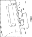
- FIG. 23 depicts a perspective view of an alternate living hinge clip 584 that may be incorporated on a lid (e.g., lid 16).
- a living hinge portion 594 of the clip 584 permits a lid assembly (e.g., lid assembly 14) to pivot between the closed position and the opened position.
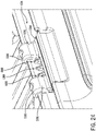
- each clip 584 Adjacent the living hinge portion 594, each clip 584 includes an exterior clip portion 596 and an interior clip portion 598. As shown in FIG. 24 , the exterior clip portion 596 and the interior clip portion 598 are generally C-shaped, and a gap in the exterior clip portion 596 permits the clip 584 to be located around the detent rib components 488.
- the rib components 488 create an audible signal (e.g., a snapping sound) that the clip 584 has been successfully located on the receptacle.
- the rib components 488 act to retain the clip 584 on the receptacle.
- an alternate cover 600 is depicted according to an exemplary implementation. Similar to the cover 18 (depicted in FIGS. 13-15 ), the alternate cover 600 includes a central wall 646. However, unlike the cover 18, the central wall 646 is surrounded only by an upwardly sloping peripheral wall 650, rather than both downwardly sloping and upwardly sloping walls.
- the upwardly sloping peripheral wall 650 is shown to terminate in a horizontal lip 652, and stacking recesses 654 are formed in each of the corners of the upwardly sloping peripheral wall 656.
- a stacking ridge 656 extends upwardly from the central wall 646.
- the stacking ridge 656 has a generally rectangular-shaped perimeter, and together, the stacking recesses 654 and the stacking ridge 656 interact with corresponding features (e.g., interlocking protrusions, recesses) located on an exterior surface of a bottom wall (e.g., bottom wall 60) of a receptacle (e.g., receptacle 12, receptacle 400) to limit relative movement of the cover 600 and a receptacle stacked atop the cover 600.
- a bottom wall e.g., bottom wall 60
- a receptacle e.g., receptacle 12, receptacle 400
- the cover 600 is further shown to include generally arc-shaped retaining protrusions 658 extending outwardly from the peripheral wall 650 opposite the stacking recesses 654.
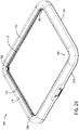
- FIG. 26 depicts an alternate lid 700 that is configured to be mated to the cover 600 using the retaining protrusions 658.
- the lid 700 generally consists of an outer surface 774 that extends from an inner peripheral edge 776 to an outer peripheral edge 778.
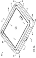
- An arc-shaped cover receiving tab 780 is formed in each of the corners of the 774, and as shown in the cross-sectional view of FIG. 27 , the retaining protrusions 658 are configured to fit within recesses in the corner receiving tabs 780 to retain the cover 600 when the cover 600 is coupled to the lid 700.
- FIGS. 28 and 29 depict perspective and side cross-sectional views of another alternate cover 800.
- the cover 800 may be coupled to the lid 16 (depicted in FIGS. 9-10 ).
- the cover 800 is shown to include a central wall 802 surrounded by an upwardly sloping peripheral wall 804. Corner walls 806 extend downwardly from the peripheral wall 804 and over a portion of the outer surface 74 of the lid 16.
- a generally arc-shaped retaining protrusion 808 extends inwardly from each of the corner walls 806.
- the retaining protrusions 808 fit underneath the outer peripheral edge 78 of the lid 16 to retain the cover 800 when the cover 800 is coupled to the lid 16.
Landscapes
- Engineering & Computer Science (AREA)
- Food Science & Technology (AREA)
- Mechanical Engineering (AREA)
- Physics & Mathematics (AREA)
- Thermal Sciences (AREA)
- Closures For Containers (AREA)
- Packages (AREA)
- Packging For Living Organisms, Food Or Medicinal Products That Are Sensitive To Environmental Conditiond (AREA)
- Cookers (AREA)
Applications Claiming Priority (1)
| Application Number | Priority Date | Filing Date | Title |
|---|---|---|---|
| US17/104,920 US11889949B2 (en) | 2020-11-25 | 2020-11-25 | Decorative holder for foodstuff trays, tins, and pans |
Publications (1)
| Publication Number | Publication Date |
|---|---|
| EP4011248A1 true EP4011248A1 (fr) | 2022-06-15 |
Family
ID=78789828
Family Applications (1)
| Application Number | Title | Priority Date | Filing Date |
|---|---|---|---|
| EP21210438.4A Pending EP4011248A1 (fr) | 2020-11-25 | 2021-11-25 | Support décoratif pour plateaux, boîtes et casseroles de produits alimentaires |
Country Status (6)
| Country | Link |
|---|---|
| US (3) | US11889949B2 (fr) |
| EP (1) | EP4011248A1 (fr) |
| CN (1) | CN114537845A (fr) |
| AU (1) | AU2021261906B2 (fr) |
| CA (1) | CA3138317A1 (fr) |
| MX (1) | MX2021014112A (fr) |
Families Citing this family (6)
| Publication number | Priority date | Publication date | Assignee | Title |
|---|---|---|---|---|
| USD1048822S1 (en) * | 2020-04-02 | 2024-10-29 | Sugar Beets, LLC | Egg tray |
| US11889949B2 (en) | 2020-11-25 | 2024-02-06 | Sugar Beets, LLC | Decorative holder for foodstuff trays, tins, and pans |
| WO2022192253A1 (fr) * | 2021-03-08 | 2022-09-15 | Kovatch David | Dispositif d'empilement de contenants alimentaires |
| US11738914B2 (en) | 2021-11-18 | 2023-08-29 | Yeti Coolers, Llc | Container and latching system |
| US11707159B1 (en) * | 2022-06-01 | 2023-07-25 | Meitar Shukrun | Electric platter |
| US12497212B1 (en) | 2025-01-28 | 2025-12-16 | Daniel Paul Scott Gilbert | Holder for containers in the form of a frame |
Citations (6)
| Publication number | Priority date | Publication date | Assignee | Title |
|---|---|---|---|---|
| US20060076352A1 (en) * | 2004-10-13 | 2006-04-13 | Rubbermaid Incorporated | Container with integral foam gasket and method of making the container |
| US20150053676A1 (en) * | 2013-08-21 | 2015-02-26 | Michelle Sand | Multi-tier assembly for supporting such as ice cream cones and cupcakes in spatially stacked fashion |
| US20150210464A1 (en) * | 2014-01-29 | 2015-07-30 | Maureen Carroll | Hot or Cold Dual Insulating Food Service Assembly |
| US20160249768A1 (en) | 2015-02-27 | 2016-09-01 | Sugar Beets, LLC | Decorative holder for serving/catering trays and tins |
| WO2017001083A1 (fr) * | 2015-06-30 | 2017-01-05 | Rotho Advanced Solutions Ag | Récipient de stockage empilable |
| US10392165B2 (en) * | 2015-02-25 | 2019-08-27 | Ideastream Consumer Products, Llc | Method for sealing materials |
Family Cites Families (101)
| Publication number | Priority date | Publication date | Assignee | Title |
|---|---|---|---|---|
| US926648A (en) * | 1908-02-26 | 1909-06-29 | Thomas S Friend | Corrugated-metal jacket. |
| US1165304A (en) * | 1915-01-15 | 1915-12-21 | Thomas L Whittaker | Ice-cream-cone tray. |
| US2064411A (en) | 1936-02-08 | 1936-12-15 | Samuel J Brandstein | Combination bowl and adjustable moisture tight cover therefor |
| US2146190A (en) | 1936-08-01 | 1939-02-07 | John W Luke | Means for securing covers to receptacles |
| US2210521A (en) * | 1939-07-29 | 1940-08-06 | Kenneth E Bemis | Combined cooking, baking, and serving unit |
| US2583350A (en) * | 1948-05-08 | 1952-01-22 | Gen Electric | Hinged box |
| US2746081A (en) * | 1954-10-07 | 1956-05-22 | Pyro Plastics Corp | Container hinge assembly |
| GB862424A (en) * | 1956-10-05 | 1961-03-08 | Star Aluminium Company Ltd | Improvements relating to containers |
| US3069043A (en) | 1959-09-23 | 1962-12-18 | Aluminum Co Of America | Food package |
| US3091357A (en) * | 1961-09-05 | 1963-05-28 | Weinhart Martin | Device for hinging covers on containers |
| US3130288A (en) * | 1961-11-21 | 1964-04-21 | Foster F Monaco | Food-service device |
| US3338468A (en) * | 1965-05-24 | 1967-08-29 | Banner Metals Inc | Receptacle |
| US3285464A (en) * | 1965-05-24 | 1966-11-15 | Luxe Reading Corp De | Display box comprising hingedly connected sections |
| US3484035A (en) * | 1968-01-08 | 1969-12-16 | Dart Ind Inc | Multipurpose container |
| US3443714A (en) * | 1968-01-18 | 1969-05-13 | Illinois Tool Works | Double wall container |
| US3516115A (en) * | 1968-04-24 | 1970-06-23 | Wilson Mfg Co | Plastic hinge |
| US3782592A (en) * | 1970-04-06 | 1974-01-01 | Bergh Bros Co | Hinge mounting means |
| SE357934B (fr) * | 1971-11-01 | 1973-07-16 | Sprinter Pack Ab | |
| US4002773A (en) * | 1974-11-21 | 1977-01-11 | Entenmann's Bakery, Inc. | Baking and packaging system |
| US4212415A (en) * | 1978-01-09 | 1980-07-15 | Refreshment Machinery Incorporated | Housing and module therefor |
| US4216862A (en) * | 1979-04-23 | 1980-08-12 | Dart Industries Inc. | Children's lunch box |
| US4282983A (en) * | 1980-07-14 | 1981-08-11 | Owens-Illinois, Inc. | Container with improved spring-like hinge |
| US4366915A (en) * | 1980-09-17 | 1983-01-04 | Revlon Inc. | Hinged lid container |
| US4720023A (en) | 1982-09-29 | 1988-01-19 | Jeff Michael J | Combination insulated mug and beverage can holder |
| US4807776A (en) | 1987-09-04 | 1989-02-28 | Taco Bell | Multi-compartmented container arrangement |
| US5048715A (en) * | 1989-09-07 | 1991-09-17 | Dart Industries, Inc. | Closure assembly with hinged cover |
| US5307647A (en) | 1992-04-09 | 1994-05-03 | Mcclure Ralph K | Food serving refrigerant device |
| USD348378S (en) * | 1992-08-07 | 1994-07-05 | Crane Joan T | Cupcake holder |
| JP2582779Y2 (ja) * | 1993-10-12 | 1998-10-08 | 住友電装株式会社 | 電気接続箱のロック構造 |
| US5539955A (en) * | 1994-03-03 | 1996-07-30 | Henschel-Steinau, Inc. | Adhesive mounted plastic hinges |
| US5513909A (en) * | 1994-08-02 | 1996-05-07 | Maytag Corporation | Appliance hinge |
| US5538136A (en) * | 1995-02-07 | 1996-07-23 | Dart Industries Inc. | Egg-storer |
| US5899353A (en) * | 1995-06-07 | 1999-05-04 | Sabin; Jeffrey Michael | Ice cream cone cake holder |
| US5701757A (en) * | 1996-06-28 | 1997-12-30 | Heverly; Marilou | Portable refrigerater food container |
| CA2208627C (fr) * | 1997-06-23 | 2005-02-22 | Kenneth B. Fowlston | Articulation pour raccorder un couvercle a une boite |
| US5964368A (en) | 1997-08-05 | 1999-10-12 | Schramm; Michael A. | Elastic loop closure holder |
| USD396999S (en) * | 1997-10-14 | 1998-08-18 | Boothe Diana S | Cake carrier |
| US5912033A (en) * | 1998-03-12 | 1999-06-15 | Ferguson; Kathy | Baked goods container |
| US6146673A (en) * | 1998-03-12 | 2000-11-14 | Ferguson; Kathy | Baked goods container |
| US5967323A (en) * | 1998-06-26 | 1999-10-19 | Siragusa; Sussan | Portable cupcake riddle |
| NL1009571C2 (nl) | 1998-07-06 | 2000-01-10 | Sara Lee De Nv | Samenstel van een diepvriestaart en een wegwerpschaal, alsmede werkwijze voor het ontdooien van een diepvriestaart. |
| USD436502S1 (en) * | 1999-10-14 | 2001-01-23 | Helene M. Brock | Cupcake holder |
| US6296120B1 (en) * | 2000-02-07 | 2001-10-02 | Wegman's Food Markets, Inc. | Multiple pastry box |
| US6313446B1 (en) | 2000-08-21 | 2001-11-06 | Teresa A. Jones | Disposable liner and cooker system with disposable liner |
| US6450341B1 (en) * | 2001-02-09 | 2002-09-17 | Oven Ready Foods Llc | Shipping and baking package for food items |
| FR2833394B1 (fr) * | 2001-12-10 | 2004-03-19 | Store Electronic Systems Techn | Support d'etiquette destine a etre fixe a une etagere a chant etroit |
| US20030116572A1 (en) | 2001-12-20 | 2003-06-26 | World Kitchen, Inc. | Sealing cover for a container |
| US6901632B2 (en) * | 2003-09-15 | 2005-06-07 | Deere & Company | Coupling assembly |
| JP2007507258A (ja) * | 2003-10-09 | 2007-03-29 | ゴメス,ジュリオ,アントニオ | 電子レンジ加熱および食品の調理のための支持器具 |
| ES2368905T3 (es) * | 2003-11-06 | 2011-11-23 | Magic Production Group (M.P.G.) S.A. | Recipiente para regalos. |
| JP2005160222A (ja) * | 2003-11-26 | 2005-06-16 | Yazaki Corp | プロテクタのロック構造およびワイヤハーネス |
| US7131289B2 (en) * | 2004-06-29 | 2006-11-07 | The Glad Products Company | Container |
| US7288745B2 (en) * | 2004-10-29 | 2007-10-30 | Frank Colonna | Temperature controlled food storage and serving pan |
| DE102005011374B3 (de) | 2005-03-11 | 2006-07-13 | Infineon Technologies Ag | Sicheres und schnelles Rechenwerk für Addiereschaltungen von Kryptographieprozessoren |
| US7614518B2 (en) * | 2005-04-08 | 2009-11-10 | Bradshaw International, Inc. | Holder for baked goods |
| US20060266757A1 (en) | 2005-05-31 | 2006-11-30 | Enrique Camacho | Reinforced silicone elastomer cookware |
| EP1731442A1 (fr) * | 2005-06-06 | 2006-12-13 | VANHOUTTE, Guy | Boîte |
| US20070007291A1 (en) * | 2005-07-01 | 2007-01-11 | Jennifer Gunn | Container for carrying and transporting cupcakes and other pastry items |
| USD572539S1 (en) * | 2005-08-01 | 2008-07-08 | Wilton Industries, Inc. | Combined cake and muffin carrier |
| US8016153B2 (en) * | 2005-08-22 | 2011-09-13 | The Coleman Company, Inc. | Method and apparatus for attaching a lid to an insulated container |
| US7832586B2 (en) * | 2005-12-19 | 2010-11-16 | Pwp Industries, Inc. | Multi-compartment container system |
| USD553902S1 (en) * | 2006-03-10 | 2007-10-30 | Bradshaw International, Inc. | Holder for baked goods |
| US7775395B2 (en) * | 2007-08-03 | 2010-08-17 | Huhtamaki, Inc. | Hinged lid for a food container |
| US7922027B2 (en) | 2007-09-11 | 2011-04-12 | Wasatch Manufacturing, Llc | Food pan having elastomeric heat and scratch resistant protective flange gasket |
| US20090255937A1 (en) * | 2008-04-03 | 2009-10-15 | Hartz Bobbi L | Food storage and transport device |
| US8844764B2 (en) * | 2009-02-11 | 2014-09-30 | Progressive International Corporation | Baked goods carrier |
| USD597370S1 (en) * | 2009-04-08 | 2009-08-04 | Watkins Anna L | Mini cone baking pan |
| US20110108553A1 (en) * | 2009-11-11 | 2011-05-12 | Pantelleria Joseph A | Container/lid assembly |
| US9457941B2 (en) | 2010-02-03 | 2016-10-04 | Tomoya Kawakami | Multipurpose elastic loop gasket |
| WO2011146935A2 (fr) | 2010-05-21 | 2011-11-24 | Miller Dennis L | Dispositif de protection de récipient |
| CA2804660C (fr) | 2010-07-05 | 2018-05-29 | Get-A-Grip Chafing Pans, Llc | Poignee de poelon a fixation rapide pour disposition et retrait sur un poelon et pour stockage de poelons emboites |
| US8308021B2 (en) | 2010-08-12 | 2012-11-13 | S.C. Johnson & Son, Inc. | Disposable storage container |
| US8464889B1 (en) * | 2010-10-04 | 2013-06-18 | Lois Keithley | Transportable pastry container |
| EP2646342A1 (fr) | 2010-12-01 | 2013-10-09 | MeadWestvaco Corporation | Récipient en carton refermable |
| US8919590B2 (en) * | 2010-12-29 | 2014-12-30 | Whirlpool Corporation | Mixing bowl liner and lid |
| USD659483S1 (en) * | 2011-08-24 | 2012-05-15 | RL Industry Company Ltd. | Cupcake carrier |
| US20130071531A1 (en) * | 2011-09-18 | 2013-03-21 | RL Industry Company Ltd. | Mobile muffin container |
| USD699081S1 (en) * | 2011-12-20 | 2014-02-11 | RL Industry Company Ltd. | Cupcake carrier |
| WO2013163583A2 (fr) * | 2012-04-27 | 2013-10-31 | Abbott Laboratories | Contenant |
| US8545914B1 (en) * | 2012-05-31 | 2013-10-01 | Focus Products Group International, Llc | Food product carrier set |
| US9538882B2 (en) | 2012-09-24 | 2017-01-10 | Becky Parr | Bakeware with covered rim |
| US9414610B2 (en) * | 2012-11-21 | 2016-08-16 | Gustavo Guerrero | Egg chiller and method of use |
| USD733314S1 (en) * | 2013-09-08 | 2015-06-30 | Theranos, Inc. | Shipping container |
| US9510699B1 (en) | 2013-05-02 | 2016-12-06 | Sabine S. Miller | Serving container system |
| US8887943B1 (en) | 2013-05-02 | 2014-11-18 | Sabine S. Miller | Decorative serving container system |
| US10724253B1 (en) * | 2013-07-02 | 2020-07-28 | Bror Fries | Dual snap-in hinge and method of using the same |
| US20160021915A1 (en) * | 2014-07-24 | 2016-01-28 | Michael Wayne Baxter | Food storage container and methods of use |
| EP3247649A4 (fr) * | 2015-01-22 | 2019-01-02 | Plastek Industries, Inc. | Ensemble récipient |
| US9730555B1 (en) * | 2016-02-11 | 2017-08-15 | Robinson Home Products Inc. | Collapsible cake carrier |
| USD814885S1 (en) * | 2017-02-24 | 2018-04-10 | Sugar Beets, LLC | Holder for serving/catering trays and tins |
| USD870521S1 (en) * | 2017-07-07 | 2019-12-24 | Sugar Beets, LLC | Holder for serving/catering trays and tins |
| GB201716298D0 (en) * | 2017-10-05 | 2017-11-22 | Phillips Leanne | Cake containers |
| CN210794149U (zh) * | 2019-06-11 | 2020-06-19 | 重庆惠科金渝光电科技有限公司 | 包装箱 |
| CN210311430U (zh) * | 2019-07-23 | 2020-04-14 | 陕西睿方农业科技集团有限公司 | 一种无花果保鲜包装盒 |
| US11655097B1 (en) * | 2019-11-22 | 2023-05-23 | Julia Michelle Albert | Configurable pastry container |
| USD1048822S1 (en) * | 2020-04-02 | 2024-10-29 | Sugar Beets, LLC | Egg tray |
| USD945813S1 (en) * | 2020-07-08 | 2022-03-15 | E. Mishan & Sons, Inc. | Bakeware set |
| US11889949B2 (en) * | 2020-11-25 | 2024-02-06 | Sugar Beets, LLC | Decorative holder for foodstuff trays, tins, and pans |
| US11772857B2 (en) * | 2021-01-14 | 2023-10-03 | Beisanne ATSHAN | Food storage container having attached lid |
| USD1041264S1 (en) * | 2021-04-23 | 2024-09-10 | Sugar Beets, LLC | Decorative holder for foodstuff trays, tins, and pans |
| USD1003119S1 (en) * | 2022-02-01 | 2023-10-31 | Mr. Bar-B-Q Products Llc | Container |
-
2020
- 2020-11-25 US US17/104,920 patent/US11889949B2/en active Active
-
2021
- 2021-11-04 AU AU2021261906A patent/AU2021261906B2/en active Active
- 2021-11-09 CA CA3138317A patent/CA3138317A1/fr active Pending
- 2021-11-17 MX MX2021014112A patent/MX2021014112A/es unknown
- 2021-11-25 EP EP21210438.4A patent/EP4011248A1/fr active Pending
- 2021-11-25 CN CN202111412561.9A patent/CN114537845A/zh active Pending
-
2023
- 2023-12-20 US US18/390,622 patent/US12543888B2/en active Active
-
2025
- 2025-04-29 US US19/193,476 patent/US20250255432A1/en active Pending
Patent Citations (6)
| Publication number | Priority date | Publication date | Assignee | Title |
|---|---|---|---|---|
| US20060076352A1 (en) * | 2004-10-13 | 2006-04-13 | Rubbermaid Incorporated | Container with integral foam gasket and method of making the container |
| US20150053676A1 (en) * | 2013-08-21 | 2015-02-26 | Michelle Sand | Multi-tier assembly for supporting such as ice cream cones and cupcakes in spatially stacked fashion |
| US20150210464A1 (en) * | 2014-01-29 | 2015-07-30 | Maureen Carroll | Hot or Cold Dual Insulating Food Service Assembly |
| US10392165B2 (en) * | 2015-02-25 | 2019-08-27 | Ideastream Consumer Products, Llc | Method for sealing materials |
| US20160249768A1 (en) | 2015-02-27 | 2016-09-01 | Sugar Beets, LLC | Decorative holder for serving/catering trays and tins |
| WO2017001083A1 (fr) * | 2015-06-30 | 2017-01-05 | Rotho Advanced Solutions Ag | Récipient de stockage empilable |
Also Published As
| Publication number | Publication date |
|---|---|
| US20240115072A1 (en) | 2024-04-11 |
| MX2021014112A (es) | 2022-05-26 |
| AU2021261906B2 (en) | 2025-12-18 |
| CA3138317A1 (fr) | 2022-05-25 |
| US11889949B2 (en) | 2024-02-06 |
| CN114537845A (zh) | 2022-05-27 |
| AU2021261906A1 (en) | 2022-06-09 |
| US20220160170A1 (en) | 2022-05-26 |
| US20250255432A1 (en) | 2025-08-14 |
| US12543888B2 (en) | 2026-02-10 |
Similar Documents
| Publication | Publication Date | Title |
|---|---|---|
| US12543888B2 (en) | Decorative holder for foodstuff trays, tins, and pans | |
| US4883195A (en) | Pizza container | |
| US20210204735A1 (en) | Decorative holder for serving/catering trays and tins | |
| US5676276A (en) | Buffet table food pan | |
| US6146673A (en) | Baked goods container | |
| KR100453536B1 (ko) | 음식 서빙 및 팬 시스템 | |
| US9801488B2 (en) | Steamer container system | |
| US4908487A (en) | Egg poacher for microwave oven | |
| US5912033A (en) | Baked goods container | |
| US20100313769A1 (en) | Baking tray | |
| US20140021835A1 (en) | Countertop Oven Accessories | |
| US9675197B2 (en) | Steam cooker | |
| US5992308A (en) | Cooking vessel | |
| CA1191705A (fr) | Assiette avec couvercle a ouverture reglable | |
| USD982388S1 (en) | Unitary food container with condiment tray | |
| US20040112903A1 (en) | Bakeware and handle | |
| NZ508889A (en) | Ventilated baking tray | |
| USD483217S1 (en) | Food steamer insert | |
| GB2121673A (en) | Improvements in or relating to apparatus for serving, transporting and/or storing food or the like | |
| EP3718447B1 (fr) | Tapis de cuisson polyvalent convertible | |
| JP2777777B2 (ja) | 食品用保存容器 | |
| US20210030210A1 (en) | Stackable cookware | |
| EP2112083A1 (fr) | Récipient empilable | |
| HK1261714A1 (en) | Decorative holder for serving/catering trays and tins | |
| AU4491599A (en) | Improved baking tray |
Legal Events
| Date | Code | Title | Description |
|---|---|---|---|
| PUAI | Public reference made under article 153(3) epc to a published international application that has entered the european phase |
Free format text: ORIGINAL CODE: 0009012 |
|
| STAA | Information on the status of an ep patent application or granted ep patent |
Free format text: STATUS: THE APPLICATION HAS BEEN PUBLISHED |
|
| AK | Designated contracting states |
Kind code of ref document: A1 Designated state(s): AL AT BE BG CH CY CZ DE DK EE ES FI FR GB GR HR HU IE IS IT LI LT LU LV MC MK MT NL NO PL PT RO RS SE SI SK SM TR |
|
| STAA | Information on the status of an ep patent application or granted ep patent |
Free format text: STATUS: REQUEST FOR EXAMINATION WAS MADE |
|
| 17P | Request for examination filed |
Effective date: 20221208 |
|
| RBV | Designated contracting states (corrected) |
Designated state(s): AL AT BE BG CH CY CZ DE DK EE ES FI FR GB GR HR HU IE IS IT LI LT LU LV MC MK MT NL NO PL PT RO RS SE SI SK SM TR |