EP4011463B1 - Appareil d'exercice de flexion des bras - Google Patents
Appareil d'exercice de flexion des bras Download PDFInfo
- Publication number
- EP4011463B1 EP4011463B1 EP20932839.2A EP20932839A EP4011463B1 EP 4011463 B1 EP4011463 B1 EP 4011463B1 EP 20932839 A EP20932839 A EP 20932839A EP 4011463 B1 EP4011463 B1 EP 4011463B1
- Authority
- EP
- European Patent Office
- Prior art keywords
- frame
- fixing
- bar
- rotation
- armrest
- Prior art date
- Legal status (The legal status is an assumption and is not a legal conclusion. Google has not performed a legal analysis and makes no representation as to the accuracy of the status listed.)
- Active
Links
Images



Classifications
-
- A—HUMAN NECESSITIES
- A63—SPORTS; GAMES; AMUSEMENTS
- A63B—APPARATUS FOR PHYSICAL TRAINING, GYMNASTICS, SWIMMING, CLIMBING, OR FENCING; BALL GAMES; TRAINING EQUIPMENT
- A63B21/00—Exercising apparatus for developing or strengthening the muscles or joints of the body by working against a counterforce, with or without measuring devices
- A63B21/00058—Mechanical means for varying the resistance
- A63B21/00069—Setting or adjusting the resistance level; Compensating for a preload prior to use, e.g. changing length of resistance or adjusting a valve
-
- A—HUMAN NECESSITIES
- A63—SPORTS; GAMES; AMUSEMENTS
- A63B—APPARATUS FOR PHYSICAL TRAINING, GYMNASTICS, SWIMMING, CLIMBING, OR FENCING; BALL GAMES; TRAINING EQUIPMENT
- A63B21/00—Exercising apparatus for developing or strengthening the muscles or joints of the body by working against a counterforce, with or without measuring devices
- A63B21/06—User-manipulated weights
- A63B21/0615—User-manipulated weights pivoting about a fixed horizontal fulcrum
-
- A—HUMAN NECESSITIES
- A63—SPORTS; GAMES; AMUSEMENTS
- A63B—APPARATUS FOR PHYSICAL TRAINING, GYMNASTICS, SWIMMING, CLIMBING, OR FENCING; BALL GAMES; TRAINING EQUIPMENT
- A63B21/00—Exercising apparatus for developing or strengthening the muscles or joints of the body by working against a counterforce, with or without measuring devices
- A63B21/15—Arrangements for force transmissions
- A63B21/151—Using flexible elements for reciprocating movements, e.g. ropes or chains
-
- A—HUMAN NECESSITIES
- A63—SPORTS; GAMES; AMUSEMENTS
- A63B—APPARATUS FOR PHYSICAL TRAINING, GYMNASTICS, SWIMMING, CLIMBING, OR FENCING; BALL GAMES; TRAINING EQUIPMENT
- A63B21/00—Exercising apparatus for developing or strengthening the muscles or joints of the body by working against a counterforce, with or without measuring devices
- A63B21/15—Arrangements for force transmissions
- A63B21/151—Using flexible elements for reciprocating movements, e.g. ropes or chains
- A63B21/154—Using flexible elements for reciprocating movements, e.g. ropes or chains using special pulley-assemblies
-
- A—HUMAN NECESSITIES
- A63—SPORTS; GAMES; AMUSEMENTS
- A63B—APPARATUS FOR PHYSICAL TRAINING, GYMNASTICS, SWIMMING, CLIMBING, OR FENCING; BALL GAMES; TRAINING EQUIPMENT
- A63B21/00—Exercising apparatus for developing or strengthening the muscles or joints of the body by working against a counterforce, with or without measuring devices
- A63B21/40—Interfaces with the user related to strength training; Details thereof
- A63B21/4001—Arrangements for attaching the exercising apparatus to the user's body, e.g. belts, shoes or gloves specially adapted therefor
- A63B21/4017—Arrangements for attaching the exercising apparatus to the user's body, e.g. belts, shoes or gloves specially adapted therefor to the upper limbs
-
- A—HUMAN NECESSITIES
- A63—SPORTS; GAMES; AMUSEMENTS
- A63B—APPARATUS FOR PHYSICAL TRAINING, GYMNASTICS, SWIMMING, CLIMBING, OR FENCING; BALL GAMES; TRAINING EQUIPMENT
- A63B21/00—Exercising apparatus for developing or strengthening the muscles or joints of the body by working against a counterforce, with or without measuring devices
- A63B21/40—Interfaces with the user related to strength training; Details thereof
- A63B21/4027—Specific exercise interfaces
- A63B21/4033—Handles, pedals, bars or platforms
- A63B21/4035—Handles, pedals, bars or platforms for operation by hand
-
- A—HUMAN NECESSITIES
- A63—SPORTS; GAMES; AMUSEMENTS
- A63B—APPARATUS FOR PHYSICAL TRAINING, GYMNASTICS, SWIMMING, CLIMBING, OR FENCING; BALL GAMES; TRAINING EQUIPMENT
- A63B23/00—Exercising apparatus specially adapted for particular parts of the body
- A63B23/035—Exercising apparatus specially adapted for particular parts of the body for limbs, i.e. upper or lower limbs, e.g. simultaneously
- A63B23/12—Exercising apparatus specially adapted for particular parts of the body for limbs, i.e. upper or lower limbs, e.g. simultaneously for upper limbs or related muscles, e.g. chest, upper back or shoulder muscles
- A63B23/1281—Exercising apparatus specially adapted for particular parts of the body for limbs, i.e. upper or lower limbs, e.g. simultaneously for upper limbs or related muscles, e.g. chest, upper back or shoulder muscles primarily by articulating the elbow joint
-
- A—HUMAN NECESSITIES
- A63—SPORTS; GAMES; AMUSEMENTS
- A63B—APPARATUS FOR PHYSICAL TRAINING, GYMNASTICS, SWIMMING, CLIMBING, OR FENCING; BALL GAMES; TRAINING EQUIPMENT
- A63B2225/00—Miscellaneous features of sport apparatus, devices or equipment
- A63B2225/09—Adjustable dimensions
Definitions
- the present invention relates to an arm curl fitness apparatus, and more particularly, to an arm curl fitness apparatus capable of variously controlling a stimulation region of a biceps muscle.
- the arm curl machine one of the exercise equipment used for such weight training, allows the user to repeatedly contract and relax their biceps to grow the muscles of the biceps and increase muscle strength.
- Korean Patent Registration No. 10-1197930 (hereinafter referred to as 'cited invention') discloses an arm curl fitness apparatus.
- the user sits on the saddle (114), mounts the upper part of the arm on the upper arm support pad (103), and then holds the handle (101) with both hands and lifts it upward, thereby bending the fore part of the arm toward the upper arm.
- the angle of the upper arm support pad (103) of the cited invention is constantly fixed, stimulation is applied only to a specific part of the biceps muscle, so the user is performing additional exercise using dumbbells, etc. to apply stimulation to various parts of the biceps.
- Document KR 10 1 197 930 B1 discloses an arm curl fitness apparatus that can induce upper arm movements to develop various muscles.
- Document US 7 938 761 B2 discloses an apparatus and method for an exercise apparatus.
- the apparatus includes a base structure, a multiple axes pivotal mechanism disposed adjacent to the base structure, and an arm.
- the arm further includes a distal end portion and a proximal end portion with a longitudinal axis spanning therebetween.
- the distal and proximal end portions are each adapted to provide independent resistive force to muscle exertion, with the proximal end portion being adjacent to the mechanism such that operationally at least two independent axes of movement occur in the arm relative to the structure.
- Also included in the exercise apparatus is an assemblage for creating selectable variable resistance forces to the movement of the arm relative to the structure, such that each axis of movement has an independent selectable variable resistance force to the arm movement.
- the present invention aims to provide an arm curl fitness apparatus that can be adjusted to apply stimulation to various parts of the biceps muscle, and, thus, can effectively develop muscle and strength for the entire biceps region.
- the present invention provides an arm curl fitness apparatus in accordance with claim 1.
- An arm curl fitness apparatus comprises a first frame to be provided standing upright on both sides of the user in a straight bar shape; a second frame formed in a U-shape with each end coupled to the upper end of the first frame, inclined upwardly toward the rear, and protruding in both directions to be provided with a fixed pulley; a first rotation bar, shorter than the first frame, with one end rotatably coupled to the upper outer side of the first frame, and disposed downward; a handle formed in a L-shape with one end rotatably coupled to the first rotation bar and the other end facing the user; a second rotation bar with one end rotatably coupled to the lower outer side of the first frame, the other end fitted with a predetermined weight, and disposed to be inclined downwardly toward the rear; a wire with one end connected to a point adjacent to one end of the first rotation bar, and the other end connected to a point adjacent to the other end of the second rotation bar while wrapping around the upper side of the fixed pulley; and an
- the first frame comprises a fixed plate that forms a plate shape to be erected toward the rear at a point adjacent to the armrest; the armrest is extended so that the first fixing part and the second fixing part, forming the plate shape, are orthogonal to each other; the first fixing part is rotatably coupled to the upper inner side of the first frame; the armrest plate with a fixing piece protruding toward the outer side of the second fixing part; and cushion members provided on the inner surface of the first fixing part and on the inner surface of the second fixing part, wherein the fixing piece is provided with a first fixing pin to be inserted into the first fixing hole formed through the fixed plate, and a plurality of first fixing holes may be formed through the fixed plate along an imaginary fixing line on which the first fixing pin is positioned according to the rotation of the armrest.
- a guide plate is provided integrally with the first rotation bar to form a semicircle around one end of the first rotation bar and to be erected toward the rear, and the guide plate has a wire receiving groove along the circumference so that the wire positioned between the one end side of the first rotation bar and the fixed pulley may be guided while being positioned in the wire receiving groove.
- the present invention further comprises a third frame to be placed on the ground in a U-shape, with each end coupled to the lower ends of the first frame, and to be arranged horizontally toward the rear; a fourth frame connecting both ends of the third frame; a fifth frame vertically connecting the center of the second frame and the center of the third frame; a sixth frame hinged to the upper center of the third frame to rotate in the front-rear direction; a saddle coupled to the sixth frame to support the user's buttocks; and a backrest coupled to the upper side of the saddle on the sixth frame to support the user's back.
- the sixth frame is provided with an angle control bar having one end hinged to the rear of the sixth frame, disposed toward the fifth frame, and having a plurality of second fixing holes penetrated in the longitudinal direction; and the fifth frame has a protruding fixing bar into which the angle control bar is inserted while being disposed to face the sixth frame, and may comprise a second fixing pin penetrating the fixing bar and passing through any one of a plurality of second fixing holes.
- the saddle may be coupled to the sixth frame so as to be movable along the longitudinal direction of the sixth frame and fixed at one point.
- users can effectively develop the muscles and strength of the entire biceps muscle by applying stimulation to various parts of the biceps because they can do arm curl exercises that stimulate the biceps while adjusting the angle of the armrest that supports the triceps.
- users can widen the stimulation area of the biceps and perform arm curl exercise by adjusting the height of the saddle to suit their physical condition.
- the present invention proposes an arm curl fitness apparatus that comprises a first frame to be provided standing upright on both sides of the user in a straight bar shape so that it can be adjusted to apply stimulation to various parts of the biceps and to effectively develop muscles and strength for the entire biceps; a second frame formed in a U-shape with each end coupled to the upper end of the first frame, inclined upwardly toward the rear, and protruding in both directions to be provided with a fixed pulley; a first rotation bar, shorter than the first frame, with one end rotatably coupled to the upper outer side of the first frame, and disposed downward; a handle formed in a L-shape with one end rotatably coupled to the first rotation bar and the other end facing the user; a second rotation bar with one end rotatably coupled to the lower outer side of the first frame, the other end fitted with a predetermined weight, and disposed to be inclined downwardly toward the rear; a wire with one end connected to a point adjacent to one end of the first rotation bar
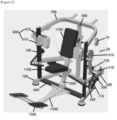
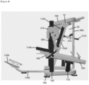
- an arm curl fitness apparatus of the present invention basically comprises a pair of first frames (100), a second frame (200), a pair of first rotation bars (300), a pair of handles (400), a pair of second rotation bars (500) , a pair of wires (30), and a pair of armrests (600) 1 .
- the first frames (100) are provided standing upright on both sides with respect to the user while each first frame is formed in a straight bar shape.
- the second frame (200) forms a U-shape, with each end of the second frame (200) coupled to the upper end of the first frames (100), respectively, and is disposed to be inclined upwardly toward the rear.
- the second frame (200) comprises a pair of fixed pulleys (10) protruded in both opposite side directions. That is, the second frame (200) is disposed toward the rear, and a pair of fixed pulleys (10) are protruded outward, respectively, in the second frame's (200)two parts facing each other 2 .
- the first rotation bar (300), shorter than the first frame (100), is disposed downward with one end rotatably coupled to the upper outer side of the first frame (100).
- the first frame (100) may be provided with a first rotation limiter (120) for limiting the rotation of the first rotation bar (300) while supporting the portion adjacent to the other end of the first rotation bar (300) from the rear.
- the other end of the first rotation bar (300) is provided with a handle (400) that the user can grip by hand, where the handle (400) forms an L-shape, and one end is rotatably coupled to the other end of the first rotation bar (300) and the other end is provided to face the user. Therefore, when the user does not lift the handle (400), the first rotation bar (300) is supported by the first rotation limiter (120) in a downwardly disposed state.
- the second rotation bar (500) is formed in a straight with one end rotatably coupled to the lower outer side of the first frame (100) and the other inclined downward toward the rear.
- the other end of the second rotation bar (500) is configured to fit a weight (20) having a predetermined weight.
- the other end of the second rotation bar (500) may have a fitting rod (510) protruding in the inner direction while forming a rod shape, and the fitting rod (510) may be fitted with a weight (20) having a fitting hole in the center, such as a barbell. Accordingly, the user can adjust the exercise intensity by adjusting the weight or the number of weights (20) fitted to the fitting rod (510).
- the wire (30) which serves to link the first rotation bar (300) and the second rotation bar (500) so that the second rotation bar (500) can rotate according to the rotation of the first rotation bar (300), has one end connected to a point adjacent to one end of the first rotation bar (300), and the other end connected to a point adjacent to the other end of the second rotation bar (500) while wrapping around the upper side of the fixed pulley (10).
- a guide plate (310) may be provided at one end of the first rotation bar (300) so that the second rotation bar (500) is easily lifted.
- the guide plate (310) may be formed in a semicircular shape around one end of the first rotation bar (300) as an embodiment, and may be provided to stand up toward the rear.
- the guide plate (310) may be provided to be integral with the first rotation bar (300) so that it can rotate together with the first rotation bar (300) when the first rotation bar (300) rotates.
- the guide plate (310) has a wire receiving groove (311) recessed along the circumference. Accordingly, the wire (30) positioned between the one end side of the first rotation bar (300) and the fixed pulley (10) may be guided while being positioned in the wire receiving groove (311).
- the wire (30) is positioned in the wire receiving groove (311) only at about 1/5 of the total length of the wire receiving groove (311), and when the first rotation bar (300) is directed forward and the second rotation bar (500) is inclined upward, the wire (30) is positioned in the wire receiving groove (311) at a portion of 1/2 or more of the total length of the wire receiving groove (311).
- the guide plate (310) also serves to maintain the wire (30) in a taut state even when the first rotation bar (300) and the second rotation bar (500) rotate repeatedly.
- the armrest (600) is provided so that the user can perform arm curl exercise in the manner described above while fixing brachial muscle.
- the armrest (600) is provided in the upper inner side of the first frame (100) so as to support the user's triceps from the back, and to adjust the angle of inclination to the ground.
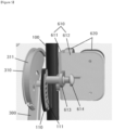
- the armrest (600) may, as shown in Figure 5 , comprise an armrest plate (610) in which the first fixing part (611) and the second fixing part (612) are extended in a plate shape to be orthogonal to each other; and a cushion member (620) to be provided on the inner surface of the first fixing part (611) and the inner surface of the second fixing part (612).
- the cushion member (620) provided on the inner surface of the first fixing part (611) supports the triceps from the side
- the cushion member (620) provided on the inner surface of the second fixing part (612) supports the triceps from the rear.
- the first fixing part (611) is rotatably coupled to the upper inner side of the first frame (100), and when considering the inclination angle of the armrest (600), it is preferable that the lower part of the first fixing part (611) is coupled to the first frame (100).
- the second fixing part (612) has a fixing piece (613) protruding outward, that is, toward the rear.
- the fixing piece (613) may be formed in a plate shape to stand up against the second fixing part (612).
- the first frame (100) is provided with a fixed plate (110) in a plate shape to be erected toward the rear at a point adjacent to the armrest (600).
- the fixing piece (613) is provided with a first fixing pin (614) to be inserted into the first fixing hole (111) that is formed through the fixed plate (110), and the fixed plate (110) has a plurality of first fixing holes (111) formed along an imaginary fixing line on which the first fixing pin (614) is positioned according to the rotation of the armrest (600).
- the user can perform an arm curl exercise that stimulates the biceps while adjusting the angle at which the brachial muscle is supported and effectively develop the muscles and strength of the entire biceps.
- an arm curl fitness apparatus of the present invention may further comprise a third frame (700), a fourth frame (800), a fifth frame (900), a sixth frame (1000), a saddle (1100), and a backrest (1200).
- the third frame (700) is placed on the ground in a U-shape to support the configuration positioned on the upper side.
- the lower ends of the first frame (100) are coupled to both ends of the third frame (700), respectively, and are arranged horizontally toward the rear.
- floor packings made of a material having frictional force such as rubber, etc., may be provided at predetermined intervals to prevent sliding in a state of being placed on the ground.
- a second rotation limiter (710) that supports the second rotation bar (500) while limiting the downward movement of the second rotation bar (500) is provided upward at a point located below the part slanted toward the other end of the second rotation bar (500). At this time, the second rotation bar (500) in contact with the second rotation limiter (710) is supported so as to be inclined downwardly toward the rear.
- the fourth frame (800) connects both ends of the third frame while forming a straight bar shape.
- the fifth frame (900) vertically connects the center of the second frame (200) and the center of the third frame (700) while forming a straight shape. That is, the portion arranged in the lateral direction in the second frame (200) and the portion arranged in the lateral direction in the third frame (700) are parallel to each other.
- the sixth frame (1000) is hinged to rotate in the front-rear direction on the upper center of the third frame (700) while forming a straight bar shape.
- the saddle (1100) has a plate shape with a predetermined thickness and is coupled to the sixth frame (1000) in a configuration in which the user's buttocks are seated, and is provided to face the front of the sixth frame (1000).
- the backrest 1200 has a plate shape having a predetermined thickness and has a configuration in which the user's back is supported, and is coupled to the sixth frame 1000 above the saddle 1100. At this time, the backrest (1200) is provided so as to be orthogonal to the saddle (1100) and parallel to the longitudinal direction of the sixth frame (1000).
- a backrest (1200) may be configured to be able to adjust the inclined angle.
- the sixth frame (1000) may have an angle control bar (1010) whose one end is hinged to the rear of the sixth frame (1000) and disposed to face the fifth frame (900), and the fifth frame (900) may have a fixing bar (910) into which the angle control bar (1010) is inserted while being set to face the sixth frame (1000).
- the angle control bar (1010) is preferably hinged to a point corresponding to the center of the backrest (1200) so that the user's back can be stably supported, and a plurality of second fixing holes (1011) may be formed to penetrate along the longitudinal direction.
- a plurality of second fixing holes (1011) are formed to penetrate in the lateral direction of the angle control bar (1010), and on the upper surface of the angle control bar (1010), a symbol indicating each step of the inclination may be displayed at each point corresponding to each second fixing hole (1011).
- a fixing bar (910) has a sighthole (911) formed through the upper surface of one end adjacent to the sixth frame (1000) so that the user can see the symbol displayed on the angle control bar (1010) through the sighthole, memorize the desired inclination step of the backrest (1200), and easily have the desired inclination even when the inclination of the backrest (1200) is changed.
- the fifth frame (900) may comprise a second fixing pin (920) passing through any one of the plurality of second fixing holes (1011) while penetrating a point adjacent to the sixth frame (1000) in the fixing bar (910).
- the second fixing pin (920) is provided separately from the fixing bar (910), and can fix the backrest (1200) not only by penetrating any one of the fixing bar (910) and a plurality of second fixing holes (1011) but also by being integrated with the fixing bar (910) and elastically protruding toward any one of the plurality of second fixing holes (1011).
- adjusting the angle of the backrest (1200) serves to control the stimulation area of the biceps muscle more widely along with the angle adjustment of the armrest (600).
- the saddle (1100) may be coupled to the sixth frame (1000) so as to be movable along the longitudinal direction of the sixth frame (1000) and fixed at one point. That is, since the height of the saddle (1100) is adjustable, the user can adjust the saddle (1100) to suit his or her physical condition and then perform the arm curl exercise.
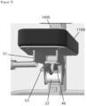
- the saddle (1100) and the sixth frame (1000) may be coupled through an interlocking member as shown in Figure 7 .
- the sixth frame (1000) has a lever stop (40) formed on the front surface at predetermined intervals along the longitudinal direction.
- the interlocking member may comprise two interlocking plates (51) that is erected on the bottom of the saddle (1100); an interlocking roller (52) whose both ends are rotatably coupled to the two interlocking plates (51) while forming a cylindrical shape and are moved when they come into contact with the sixth frame (1000) along the longitudinal direction of the sixth frame (1000); and a height control lever (53) that is rotatably coupled to the two interlocking plates (51) and caught on the lever stop (40) when it is rotated in one direction.
- the user can rotate the height control lever (54) in the other direction to release the catch of the height control lever (53), easily move the saddle (1100) along the longitudinal direction of the sixth frame (1000) through the interlocking roller (52) to adjust the height, and then rotate the height control lever (54) in one direction so that the height control lever (53) can be caught on the lever stop (40).
- a foot plate (1300) may be provided so that the user can place his or her feet while sitting on the saddle (1100).
- the foot plate (1300 in one embodiment, may be provided in the seventh frame (1400) that forms a straight line from the center of the fourth frame (800) toward the front and whose ends extend by a predetermined length in both directions, and may be provided at the ends of the portions extending in both directions from the seventh frame(1400), respectively.
- the foot plate (1300) may be provided to be spaced apart from the ground by a predetermined height, and may be provided so that an angle facing the opposite direction of the user's position forms an acute angle to the ground.
Landscapes
- Health & Medical Sciences (AREA)
- Orthopedic Medicine & Surgery (AREA)
- General Health & Medical Sciences (AREA)
- Physical Education & Sports Medicine (AREA)
- Life Sciences & Earth Sciences (AREA)
- Biophysics (AREA)
- Rehabilitation Tools (AREA)
Claims (5)
- Appareil d'exercice physique à flexion des bras, comprenant une paire de premières armatures (100), une deuxième armature (200), une paire de premières barres pivotantes (300), une paire de poignées (400), une paire de deuxièmes barres pivotantes (500), une paire de câbles (30) et une paire d'appui-bras (600) ;où les premières armatures (100) sont disposées chacune verticalement en forme de barre droite ;où la deuxième armature (200) est en forme de U, chaque extrémité de la deuxième armature (200) étant raccordée à l'extrémité supérieure respective d'une des premières armatures (100), et inclinée vers le haut et vers l'arrière,où la deuxième armature (200) comprend une paire de poulies fixes (10) formées sur des parties de la deuxième armature (200) opposées l'une à l'autre et en saillie vers l'extérieur dans des directions opposées ; où chaque première barre pivotante (300) est formée plus courte que la première armature (100), et une extrémité de chaque première barre pivotante (300) est raccordée de manière pivotante à la face extérieure supérieure respective d'une des premières armatures (100), et s'étend vers le bas ;où chaque poignée (400) est en forme de L, une extrémité de chaque poignée (400) étant raccordée de manière pivotante à une barre respective des premières barres pivotantes (300), et l'autre extrémité de la poignée (400) étant configurée pour faire face à un utilisateur et pour être saisie par l'utilisateur ;où une extrémité de chaque deuxième barre pivotante (500) est raccordée de manière pivotante à la face extérieure inférieure d'une armature respective des premières armatures (100), et l'autre extrémité de chaque deuxième barre pivotante (500) est pourvue d'un poids prédéterminé respectif, et inclinée vers le bas et vers l'arrière ;où une extrémité de chaque câble (30) est raccordée à un point adjacent à une extrémité d'une barre respective des premières barres pivotantes (300), et l'autre extrémité de chaque câble (30) est raccordée à un point adjacent à l'autre extrémité d'une barre respective des deuxièmes barres pivotantes (500), par enroulement autour de la partie supérieure d'une poulie respective entre les poulies fixes (10) ; etoù chaque appui-bras (600) est prévu à l'intérieur de la partie supérieure d'une armature respective des premières armatures (100), pour soutenir le triceps de l'utilisateur par l'arrière, où chaque appui-bras (600) est configuré pour ajuster l'angle d'inclinaison par rapport au sol.
- Appareil d'exercice physique à flexion des bras selon la revendication 1,où les premières armatures (100) sont pourvues chacune d'une plaque fixe (110) en forme de plateau dressé vers l'arrière sur un point adjacent à l'appui-bras (600) ;où chaque appui-bras (600) comprend une plaque d'appui-bras (610) où une première partie de fixation (611) et une deuxième partie de fixation (612) formant une plaque s'étendent de manière à être orthogonales l'une à l'autre, la première partie de fixation (611) étant raccordée de manière pivotante à la face intérieure supérieure de la première armature (100), et une pièce de fixation (613) est formée de manière à faire faire saillie vers la face extérieure de la deuxième partie de fixation (612), et un élément amortisseur (620) est disposé sur la surface intérieure de la première partie de fixation (611) et la surface intérieure de la deuxième partie de fixation (612),où la pièce de fixation (613) est pourvue d'une première goupille de fixation (614) à insérer dans un premier trou de fixation (111) formé au travers de la plaque fixe (110) ; etoù la plaque fixe (110) comporte une pluralité de premiers trous de fixation (111) formés le long d'une ligne de fixation imaginaire sur laquelle la première goupille de fixation (614) est positionnée en fonction du pivotement de l'appui-bras (600).
- Appareil d'exercice physique à flexion des bras selon la revendication 1,où une plaque de guidage (310) est prévue d'un seul tenant avec chacune des premières barres pivotantes (300) de manière à former un demi-cercle autour d'une extrémité de la première barre pivotante (300) et à être dressée vers l'arrière, respectivement ;où chaque plaque de guidage (310) comporte une rainure de réception de câble (311) ménagée sur la circonférence ; etoù chaque câble (30) est positionné entre le premier côté d'extrémité de la première barre pivotante respective (300) et la poulie fixe respective (10), et est guidé en étant positionné dans la rainure de réception de câble (311) de la plaque de guidage (310) respective.
- Appareil d'exercice physique à flexion des bras selon la revendication 1, comprenant en outre :une troisième armature (700) à placer sur le sol en forme de U, dont les deux extrémités sont raccordées aux extrémités inférieures respectives des premières armatures (100), et à disposer horizontalement vers l'arrière ;une quatrième armature (800) reliant les deux extrémités de la troisième armature (700) ;une cinquième armature (900) reliant verticalement le centre de la deuxième armature (200) au centre de la troisième armature (700) ;une sixième armature (1000) articulée au centre supérieur de la troisième armature (700) de manière à pivoter dans la direction avant-arrière ;une selle (1100) raccordée à la sixième armature (1000) et prévue pour supporter les fesses de l'utilisateur ; etun dossier (1200) raccordé à une face supérieure de la selle (1100) sur la sixième armature (1000) et prévu pour soutenir le dos de l'utilisateur,où la sixième armature (1000) est pourvue d'une barre de commande d'angle (1010) dont une extrémité est articulée à l'arrière de la sixième armature (1000), disposée vers la cinquième armature (900), et présentant une pluralité de deuxièmes trous de fixation (1011) ménagés dans la direction longitudinale ; etoù la cinquième armature (900) comporte une barre de fixation en saillie (910) où la barre de commande d'angle (1010) est insérée en étant disposée de manière à faire face à la sixième armature (1000), et présente une deuxième goupille de fixation (920) pénétrant dans la barre de fixation (910) et passant par l'un des trous de fixation (1011) d'une pluralité de deuxièmes trous de fixation.
- Appareil d'exercice physique à flexion des bras selon la revendication 4,
où la selle (1100) est raccordée à la sixième armature (1000) de manière à pouvoir être déplacée dans la direction longitudinale de la sixième armature (1000) et fixée sur un point.
Applications Claiming Priority (2)
| Application Number | Priority Date | Filing Date | Title |
|---|---|---|---|
| KR1020200132143A KR102225269B1 (ko) | 2020-10-13 | 2020-10-13 | 암컬 운동 기구 |
| PCT/KR2020/015765 WO2022080562A1 (fr) | 2020-10-13 | 2020-11-11 | Appareil d'exercice de flexion des bras |
Publications (4)
| Publication Number | Publication Date |
|---|---|
| EP4011463A1 EP4011463A1 (fr) | 2022-06-15 |
| EP4011463A4 EP4011463A4 (fr) | 2023-12-27 |
| EP4011463C0 EP4011463C0 (fr) | 2025-04-09 |
| EP4011463B1 true EP4011463B1 (fr) | 2025-04-09 |
Family
ID=75179929
Family Applications (1)
| Application Number | Title | Priority Date | Filing Date |
|---|---|---|---|
| EP20932839.2A Active EP4011463B1 (fr) | 2020-10-13 | 2020-11-11 | Appareil d'exercice de flexion des bras |
Country Status (5)
| Country | Link |
|---|---|
| US (1) | US11890504B2 (fr) |
| EP (1) | EP4011463B1 (fr) |
| KR (1) | KR102225269B1 (fr) |
| CN (1) | CN116113474B (fr) |
| WO (1) | WO2022080562A1 (fr) |
Families Citing this family (5)
| Publication number | Priority date | Publication date | Assignee | Title |
|---|---|---|---|---|
| KR102319729B1 (ko) * | 2021-07-22 | 2021-11-01 | (주)개선스포츠 | 하체운동장치 |
| KR102578866B1 (ko) * | 2023-03-27 | 2023-09-14 | 주식회사 인사이트 | 허리강화 운동기구 |
| USD1097009S1 (en) * | 2024-04-26 | 2025-10-07 | Newtech Wellness Corporation | Exercise handle |
| JP1794988S (ja) * | 2024-04-26 | 2025-04-02 | 運動器具用の持ち手 | |
| USD1122369S1 (en) * | 2024-10-25 | 2026-04-14 | Rorman Strength LLC | Articulating exercise handle |
Family Cites Families (22)
| Publication number | Priority date | Publication date | Assignee | Title |
|---|---|---|---|---|
| US4563003A (en) * | 1983-04-15 | 1986-01-07 | Fernando Bugallo | Weight lifting apparatus having increased force on the return stroke |
| US4720099A (en) * | 1984-11-27 | 1988-01-19 | The Toro Company | Exercise machine |
| US5273504A (en) * | 1991-09-13 | 1993-12-28 | Hammer Strength Corporation | Behind the neck pulldown exercise machine |
| US5273505A (en) * | 1991-10-21 | 1993-12-28 | Hammer Strength Corporation | High row exercise machine |
| WO1996026765A1 (fr) * | 1995-03-01 | 1996-09-06 | Cybex International, Inc. | Appareil d'exercice de developpement des epaules charge avec des plaques et methode d'exercice |
| US6913565B2 (en) * | 2001-06-20 | 2005-07-05 | Nautilus Human Performance Systems, Inc. | Biceps curl machine |
| US7654940B2 (en) | 2006-09-06 | 2010-02-02 | Hoist Fitness Systems, Inc. | Arm exercise machine with self-aligning pivoting user support |
| US7922629B1 (en) * | 2005-10-20 | 2011-04-12 | Roger Batca | Multi-station exercise gym |
| US7922630B1 (en) * | 2006-06-15 | 2011-04-12 | Roger Batca | Adjustable bicep curl support pads |
| US7938761B2 (en) * | 2008-07-09 | 2011-05-10 | Tom Simonson | Multi axes exercise apparatus |
| US7959543B2 (en) * | 2009-03-25 | 2011-06-14 | Graa Innovations, Llc | Isolated curl machine and method of training therefor |
| KR101197930B1 (ko) | 2010-05-26 | 2012-11-05 | 서울대학교산학협력단 | 팔의 상완 운동을 유발하여 다양한 근육을 발달시킬 수 있는 암컬 운동 기구 |
| KR200463829Y1 (ko) * | 2010-06-17 | 2012-11-27 | 주식회사 동아스포츠 | 하체 운동기구 |
| GB2488988B (en) * | 2011-03-09 | 2014-07-16 | Mujo Mechanics Ltd | Improved exercise apparatus |
| US8827876B2 (en) * | 2012-09-14 | 2014-09-09 | Michael Eamon Shields | Chest press machine |
| EP3326700B1 (fr) * | 2014-03-11 | 2019-02-06 | Cybex International, Inc. | Appareil d'exercice de flexion des bras |
| JP2016168337A (ja) * | 2015-03-14 | 2016-09-23 | 習之 納戸 | 足圧連動トレーニング器具 |
| CN205988516U (zh) * | 2016-08-29 | 2017-03-01 | 南通怡达运动用品有限公司 | 一种多功能举重床 |
| US10307637B2 (en) * | 2017-02-13 | 2019-06-04 | Mark Nalley | Exercise machine having horizontally extending and selectively connected weight plates |
| CN108159646A (zh) * | 2018-01-23 | 2018-06-15 | 佛山瑞箭体育器材有限公司 | 一种坐式曲臂健身器械 |
| CN108211255A (zh) * | 2018-01-23 | 2018-06-29 | 佛山瑞箭体育器材有限公司 | 一种坐式曲臂健肌器 |
| CN108211264A (zh) * | 2018-03-13 | 2018-06-29 | 佛山瑞箭体育器材有限公司 | 一种分架式曲臂健身器械 |
-
2020
- 2020-10-13 KR KR1020200132143A patent/KR102225269B1/ko active Active
- 2020-11-11 CN CN202080103668.2A patent/CN116113474B/zh active Active
- 2020-11-11 US US17/605,001 patent/US11890504B2/en active Active
- 2020-11-11 EP EP20932839.2A patent/EP4011463B1/fr active Active
- 2020-11-11 WO PCT/KR2020/015765 patent/WO2022080562A1/fr not_active Ceased
Also Published As
| Publication number | Publication date |
|---|---|
| CA3191417A1 (fr) | 2022-04-21 |
| EP4011463C0 (fr) | 2025-04-09 |
| EP4011463A1 (fr) | 2022-06-15 |
| WO2022080562A1 (fr) | 2022-04-21 |
| US11890504B2 (en) | 2024-02-06 |
| CN116113474A (zh) | 2023-05-12 |
| KR102225269B1 (ko) | 2021-03-09 |
| CN116113474B (zh) | 2024-10-01 |
| EP4011463A4 (fr) | 2023-12-27 |
| US20220305334A1 (en) | 2022-09-29 |
Similar Documents
| Publication | Publication Date | Title |
|---|---|---|
| EP4011463B1 (fr) | Appareil d'exercice de flexion des bras | |
| US5110122A (en) | Exercising apparatus and method | |
| US7585263B2 (en) | Abdominal exercise machine | |
| US9993681B2 (en) | Core training bench | |
| US6558303B1 (en) | Combination leg exercise machine with adjustable seat assembly | |
| US6652431B1 (en) | Squat exercise hook harness | |
| US11712594B2 (en) | Dual balance adjustable spring tower apparatus and method of using same | |
| US20120149540A1 (en) | Exercise apparatus adapted to facilitate stand-up crunches | |
| US6245000B1 (en) | Exercise device and body toner with adjustable inclined roller platform | |
| US11833390B2 (en) | Controlled squat strength-training machine | |
| US20190314677A1 (en) | Exercise apparatus | |
| US10960255B2 (en) | Easy chair exerciser | |
| US20020173411A1 (en) | Exercise device for exercising of the abdominal muscles | |
| US9895574B2 (en) | Exercise device for strengthening of abdominal muscles | |
| KR102191270B1 (ko) | 하체 운동기구 | |
| US7507191B2 (en) | Dual rotation rotary torso exercise bench | |
| US20070275835A1 (en) | Exercise machine | |
| CA3191417C (fr) | Appareil d'exercice de flexion des bras | |
| KR20110011842U (ko) | 복근운동기구 | |
| US20100173761A1 (en) | Dual rotation rotary torso exercise bench | |
| CN214286552U (zh) | 锻炼装置 | |
| KR102374185B1 (ko) | 상완삼두근 단련용 운동기구 | |
| WO2019097332A1 (fr) | Machine pour exercice d'activité physique assistée | |
| KR101551245B1 (ko) | 하체 운동기구 | |
| US20250161144A1 (en) | Roller Attachment Exercise Device |
Legal Events
| Date | Code | Title | Description |
|---|---|---|---|
| STAA | Information on the status of an ep patent application or granted ep patent |
Free format text: STATUS: UNKNOWN |
|
| STAA | Information on the status of an ep patent application or granted ep patent |
Free format text: STATUS: THE INTERNATIONAL PUBLICATION HAS BEEN MADE |
|
| PUAI | Public reference made under article 153(3) epc to a published international application that has entered the european phase |
Free format text: ORIGINAL CODE: 0009012 |
|
| STAA | Information on the status of an ep patent application or granted ep patent |
Free format text: STATUS: REQUEST FOR EXAMINATION WAS MADE |
|
| 17P | Request for examination filed |
Effective date: 20211104 |
|
| AK | Designated contracting states |
Kind code of ref document: A1 Designated state(s): AL AT BE BG CH CY CZ DE DK EE ES FI FR GB GR HR HU IE IS IT LI LT LU LV MC MK MT NL NO PL PT RO RS SE SI SK SM TR |
|
| RIN1 | Information on inventor provided before grant (corrected) |
Inventor name: BYUN, HYUN JUNG |
|
| A4 | Supplementary search report drawn up and despatched |
Effective date: 20231129 |
|
| RIC1 | Information provided on ipc code assigned before grant |
Ipc: A63B 21/06 20060101ALI20231123BHEP Ipc: A63B 21/00 20060101ALI20231123BHEP Ipc: A63B 23/12 20060101AFI20231123BHEP |
|
| DAV | Request for validation of the european patent (deleted) | ||
| DAX | Request for extension of the european patent (deleted) | ||
| GRAP | Despatch of communication of intention to grant a patent |
Free format text: ORIGINAL CODE: EPIDOSNIGR1 |
|
| STAA | Information on the status of an ep patent application or granted ep patent |
Free format text: STATUS: GRANT OF PATENT IS INTENDED |
|
| RIC1 | Information provided on ipc code assigned before grant |
Ipc: A63B 21/06 20060101ALI20241205BHEP Ipc: A63B 21/00 20060101ALI20241205BHEP Ipc: A63B 23/12 20060101AFI20241205BHEP |
|
| INTG | Intention to grant announced |
Effective date: 20241219 |
|
| GRAS | Grant fee paid |
Free format text: ORIGINAL CODE: EPIDOSNIGR3 |
|
| GRAA | (expected) grant |
Free format text: ORIGINAL CODE: 0009210 |
|
| STAA | Information on the status of an ep patent application or granted ep patent |
Free format text: STATUS: THE PATENT HAS BEEN GRANTED |
|
| AK | Designated contracting states |
Kind code of ref document: B1 Designated state(s): AL AT BE BG CH CY CZ DE DK EE ES FI FR GB GR HR HU IE IS IT LI LT LU LV MC MK MT NL NO PL PT RO RS SE SI SK SM TR |
|
| REG | Reference to a national code |
Ref country code: GB Ref legal event code: FG4D |
|
| REG | Reference to a national code |
Ref country code: CH Ref legal event code: EP |
|
| REG | Reference to a national code |
Ref country code: DE Ref legal event code: R096 Ref document number: 602020049357 Country of ref document: DE |
|
| REG | Reference to a national code |
Ref country code: IE Ref legal event code: FG4D |
|
| U01 | Request for unitary effect filed |
Effective date: 20250409 |
|
| U07 | Unitary effect registered |
Designated state(s): AT BE BG DE DK EE FI FR IT LT LU LV MT NL PT RO SE SI Effective date: 20250416 |
|
| PG25 | Lapsed in a contracting state [announced via postgrant information from national office to epo] |
Ref country code: ES Free format text: LAPSE BECAUSE OF FAILURE TO SUBMIT A TRANSLATION OF THE DESCRIPTION OR TO PAY THE FEE WITHIN THE PRESCRIBED TIME-LIMIT Effective date: 20250409 |
|
| PG25 | Lapsed in a contracting state [announced via postgrant information from national office to epo] |
Ref country code: GR Free format text: LAPSE BECAUSE OF FAILURE TO SUBMIT A TRANSLATION OF THE DESCRIPTION OR TO PAY THE FEE WITHIN THE PRESCRIBED TIME-LIMIT Effective date: 20250710 Ref country code: NO Free format text: LAPSE BECAUSE OF FAILURE TO SUBMIT A TRANSLATION OF THE DESCRIPTION OR TO PAY THE FEE WITHIN THE PRESCRIBED TIME-LIMIT Effective date: 20250709 |
|
| PG25 | Lapsed in a contracting state [announced via postgrant information from national office to epo] |
Ref country code: PL Free format text: LAPSE BECAUSE OF FAILURE TO SUBMIT A TRANSLATION OF THE DESCRIPTION OR TO PAY THE FEE WITHIN THE PRESCRIBED TIME-LIMIT Effective date: 20250409 |
|
| PG25 | Lapsed in a contracting state [announced via postgrant information from national office to epo] |
Ref country code: HR Free format text: LAPSE BECAUSE OF FAILURE TO SUBMIT A TRANSLATION OF THE DESCRIPTION OR TO PAY THE FEE WITHIN THE PRESCRIBED TIME-LIMIT Effective date: 20250409 |
|
| PG25 | Lapsed in a contracting state [announced via postgrant information from national office to epo] |
Ref country code: RS Free format text: LAPSE BECAUSE OF FAILURE TO SUBMIT A TRANSLATION OF THE DESCRIPTION OR TO PAY THE FEE WITHIN THE PRESCRIBED TIME-LIMIT Effective date: 20250709 |
|
| PG25 | Lapsed in a contracting state [announced via postgrant information from national office to epo] |
Ref country code: IS Free format text: LAPSE BECAUSE OF FAILURE TO SUBMIT A TRANSLATION OF THE DESCRIPTION OR TO PAY THE FEE WITHIN THE PRESCRIBED TIME-LIMIT Effective date: 20250809 |
|
| U20 | Renewal fee for the european patent with unitary effect paid |
Year of fee payment: 6 Effective date: 20251128 |
|
| PG25 | Lapsed in a contracting state [announced via postgrant information from national office to epo] |
Ref country code: SM Free format text: LAPSE BECAUSE OF FAILURE TO SUBMIT A TRANSLATION OF THE DESCRIPTION OR TO PAY THE FEE WITHIN THE PRESCRIBED TIME-LIMIT Effective date: 20250409 |
|
| PG25 | Lapsed in a contracting state [announced via postgrant information from national office to epo] |
Ref country code: CZ Free format text: LAPSE BECAUSE OF FAILURE TO SUBMIT A TRANSLATION OF THE DESCRIPTION OR TO PAY THE FEE WITHIN THE PRESCRIBED TIME-LIMIT Effective date: 20250409 |
|
| PG25 | Lapsed in a contracting state [announced via postgrant information from national office to epo] |
Ref country code: SK Free format text: LAPSE BECAUSE OF FAILURE TO SUBMIT A TRANSLATION OF THE DESCRIPTION OR TO PAY THE FEE WITHIN THE PRESCRIBED TIME-LIMIT Effective date: 20250409 |
|
| PLBE | No opposition filed within time limit |
Free format text: ORIGINAL CODE: 0009261 |
|
| STAA | Information on the status of an ep patent application or granted ep patent |
Free format text: STATUS: NO OPPOSITION FILED WITHIN TIME LIMIT |
|
| REG | Reference to a national code |
Ref country code: CH Ref legal event code: L10 Free format text: ST27 STATUS EVENT CODE: U-0-0-L10-L00 (AS PROVIDED BY THE NATIONAL OFFICE) Effective date: 20260218 |
|
| 26N | No opposition filed |
Effective date: 20260112 |