EP4011842A1 - Appareil et procédé de production d'une préforme de verre poreux - Google Patents
Appareil et procédé de production d'une préforme de verre poreux Download PDFInfo
- Publication number
- EP4011842A1 EP4011842A1 EP21214149.3A EP21214149A EP4011842A1 EP 4011842 A1 EP4011842 A1 EP 4011842A1 EP 21214149 A EP21214149 A EP 21214149A EP 4011842 A1 EP4011842 A1 EP 4011842A1
- Authority
- EP
- European Patent Office
- Prior art keywords
- glass preform
- producing
- vaporizer
- raw material
- carrier gas
- Prior art date
- Legal status (The legal status is an assumption and is not a legal conclusion. Google has not performed a legal analysis and makes no representation as to the accuracy of the status listed.)
- Granted
Links
Images

Classifications
-
- C—CHEMISTRY; METALLURGY
- C03—GLASS; MINERAL OR SLAG WOOL
- C03B—MANUFACTURE, SHAPING, OR SUPPLEMENTARY PROCESSES
- C03B37/00—Manufacture or treatment of flakes, fibres, or filaments from softened glass, minerals, or slags
- C03B37/01—Manufacture of glass fibres or filaments
- C03B37/012—Manufacture of preforms for drawing fibres or filaments
- C03B37/014—Manufacture of preforms for drawing fibres or filaments made entirely or partially by chemical means, e.g. vapour phase deposition of bulk porous glass either by outside vapour deposition [OVD], or by outside vapour phase oxidation [OVPO] or by vapour axial deposition [VAD]
- C03B37/01413—Reactant delivery systems
-
- C—CHEMISTRY; METALLURGY
- C03—GLASS; MINERAL OR SLAG WOOL
- C03B—MANUFACTURE, SHAPING, OR SUPPLEMENTARY PROCESSES
- C03B19/00—Other methods of shaping glass
- C03B19/14—Other methods of shaping glass by gas- or vapour- phase reaction processes
- C03B19/1415—Reactant delivery systems
-
- C—CHEMISTRY; METALLURGY
- C03—GLASS; MINERAL OR SLAG WOOL
- C03B—MANUFACTURE, SHAPING, OR SUPPLEMENTARY PROCESSES
- C03B37/00—Manufacture or treatment of flakes, fibres, or filaments from softened glass, minerals, or slags
- C03B37/01—Manufacture of glass fibres or filaments
- C03B37/012—Manufacture of preforms for drawing fibres or filaments
- C03B37/014—Manufacture of preforms for drawing fibres or filaments made entirely or partially by chemical means, e.g. vapour phase deposition of bulk porous glass either by outside vapour deposition [OVD], or by outside vapour phase oxidation [OVPO] or by vapour axial deposition [VAD]
- C03B37/01413—Reactant delivery systems
- C03B37/0142—Reactant deposition burners
-
- C—CHEMISTRY; METALLURGY
- C03—GLASS; MINERAL OR SLAG WOOL
- C03C—CHEMICAL COMPOSITION OF GLASSES, GLAZES OR VITREOUS ENAMELS; SURFACE TREATMENT OF GLASS; SURFACE TREATMENT OF FIBRES OR FILAMENTS MADE FROM GLASS, MINERALS OR SLAGS; JOINING GLASS TO GLASS OR OTHER MATERIALS
- C03C13/00—Fibre or filament compositions
- C03C13/04—Fibre optics, e.g. core and clad fibre compositions
-
- C—CHEMISTRY; METALLURGY
- C03—GLASS; MINERAL OR SLAG WOOL
- C03B—MANUFACTURE, SHAPING, OR SUPPLEMENTARY PROCESSES
- C03B2207/00—Glass deposition burners
- C03B2207/20—Specific substances in specified ports, e.g. all gas flows specified
- C03B2207/22—Inert gas details
-
- C—CHEMISTRY; METALLURGY
- C03—GLASS; MINERAL OR SLAG WOOL
- C03B—MANUFACTURE, SHAPING, OR SUPPLEMENTARY PROCESSES
- C03B2207/00—Glass deposition burners
- C03B2207/30—For glass precursor of non-standard type, e.g. solid SiH3F
- C03B2207/32—Non-halide
-
- C—CHEMISTRY; METALLURGY
- C03—GLASS; MINERAL OR SLAG WOOL
- C03B—MANUFACTURE, SHAPING, OR SUPPLEMENTARY PROCESSES
- C03B2207/00—Glass deposition burners
- C03B2207/36—Fuel or oxidant details, e.g. flow rate, flow rate ratio, fuel additives
-
- C—CHEMISTRY; METALLURGY
- C03—GLASS; MINERAL OR SLAG WOOL
- C03B—MANUFACTURE, SHAPING, OR SUPPLEMENTARY PROCESSES
- C03B2207/00—Glass deposition burners
- C03B2207/70—Control measures
-
- C—CHEMISTRY; METALLURGY
- C03—GLASS; MINERAL OR SLAG WOOL
- C03B—MANUFACTURE, SHAPING, OR SUPPLEMENTARY PROCESSES
- C03B2207/00—Glass deposition burners
- C03B2207/80—Feeding the burner or the burner-heated deposition site
- C03B2207/81—Constructional details of the feed line, e.g. heating, insulation, material, manifolds, filters
-
- C—CHEMISTRY; METALLURGY
- C03—GLASS; MINERAL OR SLAG WOOL
- C03B—MANUFACTURE, SHAPING, OR SUPPLEMENTARY PROCESSES
- C03B2207/00—Glass deposition burners
- C03B2207/80—Feeding the burner or the burner-heated deposition site
- C03B2207/85—Feeding the burner or the burner-heated deposition site with vapour generated from liquid glass precursors, e.g. directly by heating the liquid
Definitions
- the present invention relates to a method and an apparatus for producing a porous glass preform using an organosiloxane raw material.
- porous glass fine particle body in which soot is formed by depositing a glass fine particle on a starting material such as a glass rod
- the porous glass preform can be dehydrated and sintered so as to be a glass preform used for producing optical fibers or the like.
- the glass preform for producing optical fibers can be obtained specifically from a core preform produced by the VAD method or the like, by externally depositing thereon a SiO 2 fine particle, which are produced by combusting a silicon compound raw material such as organosiloxane, by the OVD method or the like so that a porous glass preform is produced, and sintering this porous glass preform for transparent vitrification, for example.
- Patent Document 1 describes a method for producing the glass preform by introducing and vaporizing a liquid silicone compound raw material in a vaporizer heated to a temperature from 150 to 250 degrees Celsius, combusting a vaporized raw material gas with a burner so that a SiO 2 fine particle is produced, and then depositing the SiO 2 fine particle.
- Patent Document 2 describes a method for producing the glass preform by causing a liquid raw material introduced into a vaporizer to contact with a carrier gas of a high temperature from 150 to 230 degrees Celsius and thereby vaporizing the liquid raw material, combusting a vaporized raw material gas with a burner so that a SiO 2 fine particle is produced, and depositing the SiO 2 fine particle.
- Patent Document 3 describes a method for producing a synthetic quarts glass having a polyalkylsiloxane compound containing a residual moisture concentration of at least 3ppm as a raw material.
- Patent Document 1 Japanese Patent Application Publication No. 2013-177297 .
- Patent Document 2 Japanese Translation Publication of a PCT Route Patent Application No. 2015-502316 .
- Patent Document 3 Japanese Patent No. 6661318 .
- organosiloxane in a liquid state which is represented by octamethylcyclotetrasiloxane (OMCTS)
- OCTS octamethylcyclotetrasiloxane
- a method for vaporizing a raw material in a liquid state includes a method in which the raw material is introduced into a vaporizer, the raw material is then heated in the vaporizer and vaporized, for example.
- a part of the raw material may be decomposed, polymerized, or the like, and thereby a gelatinous polymerized material may be deposited on an inner wall or a pipe of the vaporizer. If the gelatinous polymerized material is deposited on the inner wall or the pipe of the vaporizer, it causes a rise in pressure in the vaporizer, or in a worst case, the pipe will be clogged up. In order to clean the vaporizer to remove the gelatinous polymerized material, equipment needs to be stopped for a while, which will be inefficient in a production process. Also, the polymerized material depositing on the inner wall of the vaporizer may change a state of transferring heat on the inner wall of the vaporizer, and thereby a vaporization ability of the vaporizer may be reduced.
- a purpose of the present invention is to provide a method and an apparatus for producing a porous glass preform in which, if using organosiloxane in a liquid state as a raw material of a glass fine particle, a gelatinous polymerized material to be produced upon vaporizing in a vaporizer can be reduced.
- a first aspect of the present invention provides a method for producing a glass preform including mixing organosiloxane in a liquid state being a raw material with a carrier gas in a vaporizer, heating this mixture to be vaporized, supplying this vapor to a burner as a gas raw material, depositing a glass fine particle produced by combusting the gas raw material on a starting material and thereby producing a porous glass preform, and sintering the porous glass preform, herein a moisture concentration in the carrier gas to be introduced into the vaporizer is reduced to 3 volppm or less.
- a second aspect of the present invention provides an apparatus for producing a porous glass preform configured to mix organosiloxane in a liquid state being a raw material with a carrier gas in a vaporizer, heat this mixture to be vaporized, supply this vapor to a burner as a gas raw material, and produce a porous glass preform by depositing a glass fine particle produced by combusting the gas raw material on a starting material
- the apparatus for producing a porous glass preform includes a means for removing moisture configured to remove moisture in the carrier gas and supply the vaporizer with the carrier gas.
- the method and the apparatus for producing the porous glass preform in the present invention if using the organosiloxane in the liquid state as the raw material of the glass fine particle, the polymerized material to be produced upon vaporizing in the vaporizer can be reduced.
- Fig. 1 illustrates one example of a raw material supplying system of an apparatus for producing a porous glass preform 12 used for performing a method for producing the porous glass preform of the present invention.
- Organosiloxane in a liquid state (also referred to as a "raw material solution”) is injected from a raw material solution injecting pipe to a raw material solution tank 1 and stored therein, and then conducted toward a vaporizer 6.
- a liquid conducting pump, gas pressure feeding, or the like can be adopted, for example.
- Fig. 1 illustrates a case in which a liquid conducting pump 2 is adopted.
- the raw material solution that has passed through the liquid conducting pump 2 is then conducted to a liquid conducting pipe.
- the liquid conducting pipe branches out to a circulation pipe 3a and a raw material solution supplying pipe 3b that leads to the vaporizer 6 along the way.
- the raw material solution supplying pipe 3b is provided with a liquid mass flow controller 5 for accurately controlling a mass flow rate of the raw material solution along the way.
- the liquid conducting pipe is preferably heated to an extent not to solidify the raw material solution to be conducted.
- the raw material solution having a mass flow rate controlled by the liquid mass flow controller 5 is then supplied to the vaporizer 6.
- the vaporizer 6 is supplied with the raw material solution supplied through the raw material solution supplying pipe 3b, as well as a carrier gas that has passed through a carrier gas supplying pipe 3c.
- the carrier gas supplying pipe 3c is provided with a gas mass flow controller 7 along the way.
- a raw material mixed gas generated by mixing and heating the raw material solution and the carrier gas in the vaporizer 6 is supplied to a burner 13 in the apparatus for producing the porous glass preform 12 through the raw material mixed gas pipe 3d.
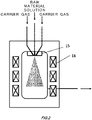
- Fig. 2 illustrates one example of a configuration of the vaporizer 6 used for performing the method for producing the porous glass preform of the present invention.
- the vaporizer 6 includes an atomizer 15 for jetting out the raw material solution and the carrier gas into the vaporizer 6, and a heater 16 for heating an inner wall.
- the atomizer 15 jets out the raw material solution from the middle, as well as the carrier gas from around the middle.
- the raw material solution is crushed by a flow of the carrier gas and turns into fine droplets, and then sprayed from the atomizer 15 being a starting point in a conical shape having a predetermined spraying angle.
- the sprayed droplets of the raw material solution are heated and vaporized in the vaporizer 6.
- the heating is performed by heat conducted from a preheated carrier gas that surrounds a droplet of the raw material solution, radiant heat from the inner wall of the vaporizer 6, and heat conducted from the inner wall to the droplet adhering to the inner wall.
- a decomposing and polymerizing reaction that derives from the raw material progresses, and thereby a polymerized material is easily deposited on the inner wall or the like.
- Octamethylcyclotetrasiloxane OCTS
- the raw material solution is supplied to the vaporizer 6 by the liquid mass flow controller 5.
- the liquid mass flow controller 5 changes a supply mass flow rate of the raw material solution within a range from 0 g/minute to 100 g/minute, for example, depending on a deposition state at a time of producing the porous glass preform.
- OMCTS organosiloxane raw material
- its purity is desirably 99% by mass or more, preferably 99.5% by mass or more, and more preferably 99.9% by mass or more.
- OMCTS is likely to contain, as impurity components, hexamethylcyclotrisiloxane (HMCTS) being a cyclic siloxane trimer, or decamethylcyclopentasiloxane (DMCPS) being a cyclic siloxane pemtamer.
- HMCTS hexamethylcyclotrisiloxane
- DCPS decamethylcyclopentasiloxane
- the carrier gas has a mass flow rate adjusted by the gas mass flow controller 7 and also is preheated by the preheater 11, followed by being supplied to the vaporizer 6.
- a preheating temperature is preferably from 200 to 300 degrees Celsius.
- the gas mass flow controller 7 supplies while changing a supply mass flow rate from 15 liter/minute (where 0 degrees Celsius, 1 atmospheric pressure conversion value) to 40 liter/minute (where 0 degrees Celsius, 1 atmospheric pressure conversion value), for example. If the carrier gas is increased, a droplet diameter of the raw material solution to be sprayed from the atomizer 15 becomes small, and thereby vaporization of the droplets progresses easily.
- the carrier gas may be preheated in the preheater 11 and supplied to the vaporizer 6.
- the preheating temperature is preferably from 200 to 300 degrees Celsius.
- a moisture concentration contained in the carrier gas to be introduced into the vaporizer is preferably reduced to 3 volppm or less.
- the moisture concentration is more preferably reduced to 1 volppm or less, or even more preferably reduced to 0.1 volppm or less.
- the linear siloxanes containing a terminal hydroxyl group forms a high molecular weight polymer when a dehydration reaction occurs. Therefore, in order to reduce the polymerized product, it is important to manage the moisture concentration in the carrier gas with which the raw material solution contacts and gets mixed, and which is heated in the vaporizer 6.
- a dew-point hygrometer 10 for measuring the dew point of the carrier gas, and a means for removing moisture 8 for reducing the moisture concentration in the carrier gas may be provided.
- the moisture concentration in the carrier gas can be checked by the dew point and a pressure.
- a volume moisture concentration is calculated from a ratio with a pressure at a measuring point of the dew-point hygrometer.
- a gauge pressure is 0.4 MPaG
- a moisture concentration is 7.85 volppm if the dew point temperature is -50 degrees Celsius, 2.16 volppm if -60 degrees Celsius, 0.52 volppm if -70 degrees Celsius, 0.11 ppm if -80 degrees Celsius, and 0.02 ppm if -90 degrees Celsius.
- a plurality of means for removing moisture 8 may be equipped in parallel, as shown in Fig. 1 .
- only one of them (8a) is used while the other (8b) is closed with a valve, and if the pipeline in use (8a) experiences reduction in its refining ability which is detected by a rise in the dew point measured by the dew-point hygrometer 10, valves are opened and closed so as to switch the pipeline to use to the other one (8b). If the pipeline (8a) of which refining ability is reduced goes through recovery operation in the meantime, moisture can be continuously removed without stopping a production process.
- a plurality of pipelines having a mass flow rate range different from each other may be equipped in parallel so as to be used by switching between them depending on a mass flow rate of the carrier gas, or a plurality of pipeline having approximately the same mass flow rate range may be equipped in parallel so that a number of the pipelines to use at the same time may be increased or decreased depending on a mass flow rate of the carrier gas. In this manner, the mass flow rate of the carrier gas can be widely changed depending on a production stage.
- an inert gas such as nitrogen, argon, or helium, or oxygen, or a mixed gas of oxygen and the inert gas may be used.
- the inert gas such as nitrogen, argon, or helium
- oxygen or a mixed gas of oxygen and the inert gas
- the carrier gas By using the inert gas such as nitrogen, argon, or helium as the carrier gas, the raw material can be safely transferred.
- Oxygen or the mixed gas of oxygen and the inert gas facilitates, if being used as the carrier gas, complete combustion by being premixed with the raw material in the vaporizer 6. Note that, it is preferable that an amount of oxygen to be supplied is enough not to cause a flashback.
- the moisture concentration in the organosiloxane raw material solution is more preferably reduced to 20 wtppm or less.
- a means for removing moisture 4 for further reducing a moisture concentration of the organosiloxane raw material may be provided in the raw material solution supplying pipe 3b.
- the means for removing moisture in the solution activated carbon, silica gel, zeolite, or the like can be used. For example, by using a molecular sieve made by Tomoe Engineering Co. Ltd. the moisture concentration in the raw material solution can be reduce to a few wtppm.
- the raw material mixed gas in which the vaporized raw material gas and the carrier gas are mixed in the vaporizer 6 is supplied to the burner 13 through a raw material mixed gas pipe 3d.
- the raw material mixed gas pipe 3d is preferably heated to a liquefaction temperature or higher, which is calculated from a partial pressure of the raw material mixed gas.
- the liquefaction temperature is 175 degrees Celsius when the partial pressure is 1 atm, and 134 degrees Celsius when 0.3 atm.
- an electric heater may be used for heating the raw material mixed gas pipe 3d.
- oxygen may be used as the carrier gas and mixed with the raw material in the vaporizer 6, or the inert gas such as nitrogen may be used as the carrier gas and oxygen may be mixed with the raw material mixed gas on the downstream side of the vaporizer 6. If mixing oxygen and the raw material mixed gas on the downstream side of the vaporizer 6, in order to prevent the raw material gas component to be reliquefied, oxygen may be preheated and then mixed with the raw material mixed gas.
- a gas to be supplied to the burner 13 includes, apart from the premixed raw material mixed gas, a seal gas, a combustible gas for combustion, oxygen gas for combustion, and the like.
- a combustible gas for combustion hydrogen, methane, ethane, propane, or the like may be used, for example.
- the vaporizer 6 illustrates in Fig. 2 was used for producing a porous glass preform 14. Specifically, the vaporizer 6 was in a cylindrical shape of which inner wall had a diameter of 40 mm and height was 120 mm, and one bottom surface of the cylinder was provided with the atomizer 15 so that droplets were jetted out in a direction toward the other bottom surface. The vaporizer 6 was controlled so that the inner wall had a temperature of 185 degrees Celsius.
- OMCTS being the organosiloxane raw material was supplied to the vaporizer 6 at a mass flow rate of 65 g/minute.
- a weight fraction of a moisture concentration in OMCTS was 15 wtppm (weight ppm) (measured by Karl Fischer coulometric titration).
- Nitrogen in the carrier gas had a mass flow rate controlled to be 30 liter/minute (0 degrees Celsius, 1 atmospheric pressure conversion value) by the gas mass flow controller while being supplied to the vaporizer 6.
- the carrier gas had the dew point maintained at -69 to -68 degrees Celsius (where measurement precision being ⁇ 2 degrees Celsius) at the dew-point hygrometer 10 right before the vaporizer, and was preheated to 250 degrees Celsius by the preheater 11 and supplied to the vaporizer 6.
- the dew-point hygrometer used was a Hygrotec (registered trademark) made by General Eastern Instruments.
- the pressure gauge 9 measured a gauge pressure of 0.4 MPaG.
- the moisture concentration in the carrier gas calculated from the pressure and the dew point is, taking a measurement error into consideration, 0.44 to 0.92 volppm (volume ppm). Then, the raw material mixed gas generated in the vaporizer 6 was supplied to the burner 13 in which a SiO 2 fine particle was then produced, the SiO 2 fine particle was deposited on the starting material to as to form the porous glass preform 14, then the porous glass preform 14 was sintered and thereby the transparent glass preform was produced.
- the vaporizer 6 was disassembled, and a weight of a gel adhering to the inner surface of the vaporizer 6 was measured as 1.3 g.
- the porous glass preform 14 was produced by the vaporizer 6 illustrated in Fig. 2 .
- the vaporizer 6 had a temperature controlled so as to be 185 degrees Celsius.
- OMCTS being the organosiloxane raw material was supplied to the vaporizer 6 at a mass flow rate of 65 g/minute.
- a weight fraction of the moisture concentration in OMCTS was 15 wtppm (measured by Karl Fischer coulometric titration).
- Air in the carrier gas had a mass flow rate controlled to be 30 liter/minute (0 degrees Celsius, 1 atmospheric pressure conversion value) by the gas mass flow controller while being supplied to the vaporizer 6.
- the air in the carrier gas which came out of the mass flow controller contained moisture so that the moisture was removed by the means for removing moisture (the piofine-cartridge made by Japan Pionics Co. Ltd.
- the dew point of the air was maintained at -69 to -68 degrees Celsius (where measurement precision being ⁇ 2 degrees Celsius) at the dew-point hygrometer 10 right before the vaporizer, then the air was preheated to 250 degrees Celsius in the preheater 11 and supplied to the vaporizer 6.
- the pressure gauge 9 measured a gauge pressure of 0.4 MPaG.
- the moisture concentration in the carrier gas calculated from the pressure and the dew point is, taking a measurement error into consideration, 0.44 to 0.92 volppm.
- the raw material mixed gas generated in the vaporizer 6 was supplied to the burner 13 in which a SiO 2 fine particle was then produced, the SiO 2 fine particle was deposited on the starting material to as to form the porous glass preform 14, then the porous glass preform 14 was sintered and thereby the transparent glass preform was produced.
- the vaporizer 6 was disassembled, and a weight of a gel adhering to the inner surface of the vaporizer 6 was measured as 1.1 g.
- the porous glass preform 14 was produced by the vaporizer 6 illustrated in Fig. 2 .
- the vaporizer 6 had a temperature controlled so as to be 185 degrees Celsius.
- OMCTS being the organosiloxane raw material was supplied to the vaporizer 6 at a mass flow rate of 50 g/minute.
- a weight fraction of the moisture concentration in OMCTS was 15 wtppm (measured by Karl Fischer coulometric titration).
- Nitrogen in the carrier gas had a mass flow rate controlled to be 30 liter/minute (0 degrees Celsius, 1 atmospheric pressure conversion value) by the gas mass flow controller while being supplied to the vaporizer 6.
- the nitrogen in the carrier gas which came out of the mass flow controller contained moisture and the moisture was removed by the means for removing moisture (the piofine-cartridge made by Japan Pionics Co. Ltd.
- the dew point of the nitrogen was maintained at -88 to -87 degrees Celsius (where measurement precision being ⁇ 2 degrees Celsius) at the dew-point hygrometer 10 right before the vaporizer, then the nitrogen was preheated to 250 degrees Celsius in the preheater 11 and supplied to the vaporizer 6.
- the pressure gauge 9 measured a gauge pressure of 0.4 MPaG.
- the moisture concentration in the carrier gas calculated from the pressure and the dew point is, taking a measurement error into consideration, 0.02 to 0.05 volppm.
- the raw material mixed gas generated in the vaporizer 6 was supplied to the burner 13 in which a SiO 2 fine particle was then produced, the SiO 2 fine particle was deposited on the starting material to as to form the porous glass preform 14, then the porous glass preform 14 was sintered and thereby the transparent glass preform was produced.
- the vaporizer 6 was disassembled, and a weight of a gel adhering to the inner surface of the vaporizer 6 was measured as 0.4 g.
- the porous glass preform 14 was produced by the vaporizer 6 illustrated in Fig. 2 .
- the vaporizer 6 had a temperature controlled so as to be 185 degrees Celsius.
- OMCTS being the organosiloxane raw material was supplied to the vaporizer 6 at a mass flow rate of 50 g/minute.
- a weight fraction of the moisture concentration in OMCTS was 5 wtppm (measured by Karl Fischer coulometric titration).
- Nitrogen in the carrier gas had a mass flow rate controlled to be 30 liter/minute (0 degrees Celsius, 1 atmospheric pressure conversion value) by the gas mass flow controller while being supplied to the vaporizer 6.
- the nitrogen in the carrier gas which came out of the mass flow controller contained moisture and the moisture was removed by the means for removing moisture (the piofine-cartridge made by Japan Pionics Co. Ltd.
- the dew point of the nitrogen was maintained at -88 to -87 degrees Celsius (where measurement precision being ⁇ 2 degrees Celsius) at the dew-point hygrometer 10 right before the vaporizer, then the nitrogen was preheated to 250 degrees Celsius in the preheater 11 and supplied to the vaporizer 6.
- the pressure gauge 9 measured a gauge pressure of 0.4 MPaG.
- the moisture concentration in the carrier gas calculated from the pressure and the dew point is, taking a measurement error into consideration, 0.02 to 0.05 volppm.
- the raw material mixed gas generated in the vaporizer 6 was supplied to the burner 13 in which a SiO 2 fine particle was then produced, the SiO 2 fine particle was deposited on the starting material to as to form the porous glass preform 14, then the porous glass preform 14 was sintered and thereby the transparent glass preform was produced.
- the vaporizer 6 was disassembled, and a weight of a gel adhering to the inner surface of the vaporizer 6 was measured as 0.2 g.
- the porous glass preform 13 was produced by the vaporizer 6 illustrated in Fig. 2 .
- the vaporizer 6 had a temperature controlled so as to be 185 degrees Celsius.
- OMCTS being the organosiloxane raw material was supplied to the vaporizer 6 at a mass flow rate of 65 g/minute.
- a weight fraction of the moisture concentration in OMCTS was 15 wtppm (measured by Karl Fischer coulometric titration).
- Nitrogen in the carrier gas had a mass flow rate controlled to be 20 liter/minute (0 degrees Celsius, 1 atmospheric pressure conversion value) by the gas mass flow controller while being supplied to the vaporizer 6.
- the carrier gas had the dew point of -55 to -54 degrees Celsius (where measurement precision being ⁇ 2 degrees Celsius) at the dew-point hygrometer 10 right before the vaporizer, and was preheated to 250 degrees Celsius by the preheater 11 and supplied to the vaporizer 6.
- a pressure gauge 9 measured a gauge pressure of 0.4 MPaG.
- the moisture concentration calculated from the pressure and the dew point is, taking a measurement error into consideration, 3.2 to 6.1 volppm.
- the raw material mixed gas generated in the vaporizer 6 was supplied to the burner 13 in which a SiO 2 fine particle was then produced, the SiO 2 fine particle was deposited on the starting material to as to form the porous glass preform 14, then the porous glass preform 14 was sintered and thereby the transparent glass preform was produced.
- the vaporizer 6 was disassembled, and a weight of a gel adhering to the inner surface of the vaporizer 6 was measured as 7.4 g.
- Table 1 shows the amount of the gel that was adhering to the inner surface of the vaporizer 6 in Example 1 to 4, and Comparative Example 1, together with various conditions thereof. As illustrated, by reducing the moisture concentration in the carrier gas to be introduced into the vaporizer 6 to 3 volppm or less, production of the polymerized material was reduced upon vaporizing in the vaporizer 6.
- EXAMPLE 1 EXAMPLE 2 EXAMPLE 3 EXAMPLE 4 COMPARATIVE EXAMPLE 1 MOISTURE CONCENTRATION IN OMCTS (wtppm) 15 15 15 5 15 TYPE OF CARRIER GAS NITROGEN AIR NITROGEN NITROGEN NITROGEN MOISTURE CONCENTRATION IN CARRIER GAS (volppm) 0.44 ⁇ 0.92 0.44 ⁇ 0.92 0.02 ⁇ 0.05 0.02 ⁇ 0.05 3.2 ⁇ 6.1 MASS FLOW RATE OF OMCTS (g/min) 65 65 50 50 65 MASS FLOW RATE OF CARRIER GAS (SLM) 30 30 30 30 20 AMOUNT OF GEL ADHERING (g) 1.3 1.1 0.4 0.2 7.4
- the present invention is not limited to the above embodiments or examples.
- the technical scope of the present invention includes anything that has substantially the same configuration as the technical idea described in the claims of the present invention and produces the same effects, no matter how much it has been changed.
Landscapes
- Chemical & Material Sciences (AREA)
- Engineering & Computer Science (AREA)
- Chemical Kinetics & Catalysis (AREA)
- Organic Chemistry (AREA)
- Materials Engineering (AREA)
- Manufacturing & Machinery (AREA)
- Life Sciences & Earth Sciences (AREA)
- Geochemistry & Mineralogy (AREA)
- General Chemical & Material Sciences (AREA)
- General Life Sciences & Earth Sciences (AREA)
- Physics & Mathematics (AREA)
- Optics & Photonics (AREA)
- Glass Melting And Manufacturing (AREA)
- Manufacture, Treatment Of Glass Fibers (AREA)
Applications Claiming Priority (1)
| Application Number | Priority Date | Filing Date | Title |
|---|---|---|---|
| JP2020207133A JP7428632B2 (ja) | 2020-12-14 | 2020-12-14 | 多孔質ガラス母材の製造方法及び製造装置 |
Publications (2)
| Publication Number | Publication Date |
|---|---|
| EP4011842A1 true EP4011842A1 (fr) | 2022-06-15 |
| EP4011842B1 EP4011842B1 (fr) | 2026-03-18 |
Family
ID=78851119
Family Applications (1)
| Application Number | Title | Priority Date | Filing Date |
|---|---|---|---|
| EP21214149.3A Active EP4011842B1 (fr) | 2020-12-14 | 2021-12-13 | Procédé de production d'une préforme de verre poreux |
Country Status (5)
| Country | Link |
|---|---|
| US (2) | US11667557B2 (fr) |
| EP (1) | EP4011842B1 (fr) |
| JP (1) | JP7428632B2 (fr) |
| KR (1) | KR102475516B1 (fr) |
| CN (1) | CN114620934A (fr) |
Families Citing this family (2)
| Publication number | Priority date | Publication date | Assignee | Title |
|---|---|---|---|---|
| CN111051259A (zh) * | 2017-08-29 | 2020-04-21 | 住友电气工业株式会社 | 玻璃微粒沉积体的制造方法、玻璃母材的制造方法以及玻璃母材 |
| CN121342322B (zh) * | 2025-12-22 | 2026-03-13 | 内蒙古亨芯石英有限公司 | 一种cvd法制备多孔不透明高纯石英的装置及方法 |
Citations (4)
| Publication number | Priority date | Publication date | Assignee | Title |
|---|---|---|---|---|
| JPH0361318B2 (fr) | 1986-07-04 | 1991-09-19 | Fuseso* Nauchino Isusuredo* Puroekutono Konsuto* I Tech Inst Erekutorosuwarochinobo Oborudowania | |
| JP2013177297A (ja) | 2012-02-09 | 2013-09-09 | Asahi Glass Co Ltd | ドープ石英ガラスの製造方法 |
| US20160096765A1 (en) * | 2014-10-01 | 2016-04-07 | Heraeus Quarzglas Gmbh & Co. Kg | Method for the manufacture of synthetic quartz glass |
| US20160107923A1 (en) * | 2013-05-24 | 2016-04-21 | Heraeus Quarzglas Gmbh & Co. Kg | Evaporator and method for producing synthetic fused quartz |
Family Cites Families (42)
| Publication number | Priority date | Publication date | Assignee | Title |
|---|---|---|---|---|
| JPS593940B2 (ja) * | 1975-08-02 | 1984-01-26 | 住友電気工業株式会社 | スイブンオ ガンユウシナイセキエイガラスヒマクケイセイホウ |
| US4314837A (en) | 1979-03-01 | 1982-02-09 | Corning Glass Works | Reactant delivery system method |
| JPS593942B2 (ja) | 1981-05-15 | 1984-01-26 | 日本電信電話株式会社 | ガラスフアイバ母材の製造法 |
| US5043002A (en) | 1990-08-16 | 1991-08-27 | Corning Incorporated | Method of making fused silica by decomposing siloxanes |
| JP3208673B2 (ja) * | 1991-07-09 | 2001-09-17 | 日本酸素株式会社 | ガス精製方法及び装置 |
| US5703191A (en) * | 1995-09-01 | 1997-12-30 | Corning Incorporated | Method for purifying polyalkylsiloxanes and the resulting products |
| CA2285562A1 (fr) * | 1997-04-18 | 1998-10-29 | Corning Incorporated | Processus de purification de siloxane |
| US5979185A (en) * | 1997-07-16 | 1999-11-09 | Corning Incorporated | Method and apparatus for forming silica by combustion of liquid reactants using a heater |
| US6536240B1 (en) * | 1998-04-10 | 2003-03-25 | Mikhail Ivanovich Gouskov | Method of making an optical fiber preform via multiple plasma depositing and sintering steps |
| WO1999054259A1 (fr) * | 1998-04-22 | 1999-10-28 | Corning Incorporated | Procedes de fabrication de verres en silice-anhydride titanique a expansion ultra faible |
| JP3794664B2 (ja) | 1998-07-29 | 2006-07-05 | 信越化学工業株式会社 | 合成石英ガラス部材及びその製造方法、並びにエキシマレーザ用光学部品 |
| JP2000159532A (ja) | 1998-11-19 | 2000-06-13 | Furukawa Electric Co Ltd:The | 光ファイバ用多孔質ガラス母材の製造装置 |
| JP3143445B2 (ja) | 1999-03-12 | 2001-03-07 | 信越化学工業株式会社 | 合成石英の製造方法 |
| ES2364453T3 (es) | 2001-04-27 | 2011-09-02 | Prysmian S.P.A. | Procedimiento para producir una preforma de fibra óptica. |
| JP3968451B2 (ja) | 2002-07-08 | 2007-08-29 | 昭和電線ケーブルシステム株式会社 | 光ファイバ用母材の製造方法およびその製造装置 |
| JP2004161555A (ja) | 2002-11-14 | 2004-06-10 | Sumitomo Electric Ind Ltd | ガラス形成ガスの供給方法、ガラス微粒子堆積体の製造方法及びそれぞれの装置 |
| JP4358088B2 (ja) | 2004-01-14 | 2009-11-04 | 株式会社フジクラ | 光ファイバ用多孔質ガラス母材の製造装置 |
| WO2007054961A2 (fr) | 2005-09-05 | 2007-05-18 | Sterlite Optical Technologies Ltd. | Préforme de fibre optique à grand corps poreux aux suies, et procédé d'élaboration |
| CN101292117A (zh) | 2005-10-19 | 2008-10-22 | 冈安谦治 | 使用小型气化装置的燃烧装置 |
| US7861557B2 (en) | 2005-12-29 | 2011-01-04 | Silica Tech, Llc | Plasma torch for making synthetic silica |
| KR100727362B1 (ko) | 2007-01-05 | 2007-06-13 | 주식회사 코닥트 | 소음과 분진을 저감시킨 케이블 베어 |
| JP5399798B2 (ja) | 2008-07-18 | 2014-01-29 | 信越化学工業株式会社 | 光ファイバ用母材の製造方法および光ファイバ用母材の製造装置 |
| DE102009010497A1 (de) | 2008-12-19 | 2010-08-05 | J-Fiber Gmbh | Mehrdüsiger rohrförmiger Plasma-Abscheidebrenner zur Herstellung von Vorformen als Halbzeuge für optische Fasern |
| IT1392943B1 (it) * | 2009-02-25 | 2012-04-02 | Moretto Spa | Metodo e impianto di deumidificazione di materiali in forma granulare |
| CN103842303B (zh) | 2011-09-29 | 2018-07-03 | 住友电气工业株式会社 | 玻璃微粒沉积体以及玻璃预制件的制造方法 |
| DE102011119374A1 (de) | 2011-11-25 | 2013-05-29 | Heraeus Quarzglas Gmbh & Co. Kg | Verfahren zur Herstellung von synthetischem Quarzglas |
| DE102011119339A1 (de) | 2011-11-25 | 2013-05-29 | Heraeus Quarzglas Gmbh & Co. Kg | Zerstäubungsverfahren zur Herstellung von synthetischem Quarzglas |
| DE102011121153B3 (de) | 2011-12-15 | 2013-03-21 | Heraeus Quarzglas Gmbh & Co. Kg | Verfahren zur Herstellung von synthetischem Quarzglas sowie Quarzglas für den Einsatz als Mantelmaterial einer optischen Faser |
| DE102011121190A1 (de) * | 2011-12-16 | 2013-06-20 | Heraeus Quarzglas Gmbh & Co. Kg | OMCTS-Verdampfungsverfahren |
| SG10201702197PA (en) | 2012-02-10 | 2017-04-27 | Entegris Inc | Gas purifier |
| US9695080B2 (en) | 2012-12-28 | 2017-07-04 | Sumitomo Electric Industries, Ltd. | Glass particle deposit producing method and glass preform producing method |
| CN103755135B (zh) | 2013-12-25 | 2016-08-17 | 中天科技精密材料有限公司 | 一种光纤预制棒外包层高效制备方法及其设备 |
| EP4245233A3 (fr) | 2014-10-14 | 2023-12-06 | The University of British Columbia | Systèmes de fixation d'os intramédullaire |
| JP6284275B2 (ja) | 2014-12-22 | 2018-02-28 | 信越化学工業株式会社 | 光ファイバ用母材の製造装置 |
| JP2017036172A (ja) | 2015-08-07 | 2017-02-16 | 株式会社フジクラ | 光ファイバ母材の製造方法 |
| US11577982B2 (en) | 2015-10-07 | 2023-02-14 | Corning Incorporated | Method to prevent cracks in optical fiber preforms |
| WO2018014934A1 (fr) * | 2016-07-18 | 2018-01-25 | Prysmian S.P.A. | Procédé de fabrication de préformes de dioxyde de silicium utilisées dans la production de fibres optiques |
| CN106082633B (zh) | 2016-08-22 | 2019-07-23 | 长飞光纤光缆股份有限公司 | 一种用于沉积光纤预制棒的燃烧器与沉积方法 |
| KR102014913B1 (ko) * | 2017-11-08 | 2019-08-27 | 주식회사 에스티아이 | 광섬유 모재 증착 시스템 |
| JP6793676B2 (ja) * | 2018-04-02 | 2020-12-02 | 信越化学工業株式会社 | 光ファイバ用多孔質ガラス母材の製造装置および製造方法 |
| JPWO2020054861A1 (ja) | 2018-09-14 | 2021-08-30 | 住友電気工業株式会社 | ガラス微粒子堆積体の製造方法及びガラス母材の製造方法 |
| KR102058156B1 (ko) * | 2019-03-21 | 2019-12-20 | 주식회사 케이디이앤에스 | 유량 의존 스위칭 방식의 스마트 제습장치 및 제습방법 |
-
2020
- 2020-12-14 JP JP2020207133A patent/JP7428632B2/ja active Active
-
2021
- 2021-12-01 KR KR1020210169870A patent/KR102475516B1/ko active Active
- 2021-12-02 CN CN202111462967.8A patent/CN114620934A/zh active Pending
- 2021-12-13 US US17/644,083 patent/US11667557B2/en active Active
- 2021-12-13 EP EP21214149.3A patent/EP4011842B1/fr active Active
-
2023
- 2023-03-27 US US18/190,948 patent/US12509387B2/en active Active
Patent Citations (4)
| Publication number | Priority date | Publication date | Assignee | Title |
|---|---|---|---|---|
| JPH0361318B2 (fr) | 1986-07-04 | 1991-09-19 | Fuseso* Nauchino Isusuredo* Puroekutono Konsuto* I Tech Inst Erekutorosuwarochinobo Oborudowania | |
| JP2013177297A (ja) | 2012-02-09 | 2013-09-09 | Asahi Glass Co Ltd | ドープ石英ガラスの製造方法 |
| US20160107923A1 (en) * | 2013-05-24 | 2016-04-21 | Heraeus Quarzglas Gmbh & Co. Kg | Evaporator and method for producing synthetic fused quartz |
| US20160096765A1 (en) * | 2014-10-01 | 2016-04-07 | Heraeus Quarzglas Gmbh & Co. Kg | Method for the manufacture of synthetic quartz glass |
Also Published As
| Publication number | Publication date |
|---|---|
| KR102475516B1 (ko) | 2022-12-07 |
| EP4011842B1 (fr) | 2026-03-18 |
| CN114620934A (zh) | 2022-06-14 |
| US20220185719A1 (en) | 2022-06-16 |
| JP2022094218A (ja) | 2022-06-24 |
| US12509387B2 (en) | 2025-12-30 |
| KR20220085008A (ko) | 2022-06-21 |
| JP7428632B2 (ja) | 2024-02-06 |
| US20230227345A1 (en) | 2023-07-20 |
| US11667557B2 (en) | 2023-06-06 |
Similar Documents
| Publication | Publication Date | Title |
|---|---|---|
| KR101569797B1 (ko) | 합성 석영 유리의 제조 방법 | |
| US20230227345A1 (en) | Apparatus and method for producing porous glass preform | |
| KR101569790B1 (ko) | 수트법에 따른 합성 석영 유리 제조 방법 | |
| EP3549921B1 (fr) | Appareil et procédé de fabrication d'une préforme de verre poreux pour fibre optique | |
| US10399888B2 (en) | Method for producing glass particulate deposit and method for producing glass preform | |
| EP3450407B1 (fr) | Procédé de fabrication d'une matrice de verre | |
| KR101628043B1 (ko) | 지지체상에서 증기상으로부터 실리카 수트의 증착에 의한 합성 석영 유리 제조 방법 | |
| KR101628038B1 (ko) | 지지체상에서 증기상으로부터 SiO2 수트의 증착에 의한 합성 석영 유리 제조 방법 | |
| JP7058627B2 (ja) | 光ファイバ用多孔質ガラス母材の製造装置および製造方法 | |
| JP2013177297A (ja) | ドープ石英ガラスの製造方法 | |
| KR20150116453A (ko) | 티타늄-도핑된 합성 석영 유리의 생산방법 | |
| US20150128650A1 (en) | Method for producing glass particulate deposit and method for producing glass preform | |
| KR100567453B1 (ko) | 합성석영글래스제조방법 | |
| JP2018193279A (ja) | ガラス微粒子堆積体の製造方法、ガラス母材の製造方法及びガラス微粒子堆積体 | |
| JP2004509041A (ja) | チタニアドープ石英ガラスプリフォームの作成方法 | |
| EP3878823B1 (fr) | Procédé de fabrication d'un matériau de base de verre poreux pour fibre optique | |
| JP2016121070A (ja) | ガラス微粒子堆積体の製造方法およびガラス母材の製造方法 | |
| JP7449842B2 (ja) | 多孔質ガラス母材の製造方法及び製造装置 | |
| JP2022093384A (ja) | 光ファイバ用多孔質ガラス母材の製造方法 |
Legal Events
| Date | Code | Title | Description |
|---|---|---|---|
| PUAI | Public reference made under article 153(3) epc to a published international application that has entered the european phase |
Free format text: ORIGINAL CODE: 0009012 |
|
| STAA | Information on the status of an ep patent application or granted ep patent |
Free format text: STATUS: EXAMINATION IS IN PROGRESS |
|
| 17P | Request for examination filed |
Effective date: 20211213 |
|
| AK | Designated contracting states |
Kind code of ref document: A1 Designated state(s): AL AT BE BG CH CY CZ DE DK EE ES FI FR GB GR HR HU IE IS IT LI LT LU LV MC MK MT NL NO PL PT RO RS SE SI SK SM TR |
|
| GRAP | Despatch of communication of intention to grant a patent |
Free format text: ORIGINAL CODE: EPIDOSNIGR1 |
|
| STAA | Information on the status of an ep patent application or granted ep patent |
Free format text: STATUS: GRANT OF PATENT IS INTENDED |
|
| INTG | Intention to grant announced |
Effective date: 20251014 |
|
| GRAS | Grant fee paid |
Free format text: ORIGINAL CODE: EPIDOSNIGR3 |
|
| GRAA | (expected) grant |
Free format text: ORIGINAL CODE: 0009210 |
|
| STAA | Information on the status of an ep patent application or granted ep patent |
Free format text: STATUS: THE PATENT HAS BEEN GRANTED |
|
| AK | Designated contracting states |
Kind code of ref document: B1 Designated state(s): AL AT BE BG CH CY CZ DE DK EE ES FI FR GB GR HR HU IE IS IT LI LT LU LV MC MK MT NL NO PL PT RO RS SE SI SK SM TR |
|
| REG | Reference to a national code |
Ref country code: CH Ref legal event code: F10 Free format text: ST27 STATUS EVENT CODE: U-0-0-F10-F00 (AS PROVIDED BY THE NATIONAL OFFICE) Effective date: 20260318 Ref country code: GB Ref legal event code: FG4D |
|
| REG | Reference to a national code |
Ref country code: DE Ref legal event code: R096 Ref document number: 602021050099 Country of ref document: DE |
|
| REG | Reference to a national code |
Ref country code: IE Ref legal event code: FG4D |