EP4012099A2 - Rouleau de compacteur pour un compacteur de sol - Google Patents
Rouleau de compacteur pour un compacteur de sol Download PDFInfo
- Publication number
- EP4012099A2 EP4012099A2 EP21206583.3A EP21206583A EP4012099A2 EP 4012099 A2 EP4012099 A2 EP 4012099A2 EP 21206583 A EP21206583 A EP 21206583A EP 4012099 A2 EP4012099 A2 EP 4012099A2
- Authority
- EP
- European Patent Office
- Prior art keywords
- unbalanced mass
- oscillation
- unbalanced
- mass
- rotation
- Prior art date
- Legal status (The legal status is an assumption and is not a legal conclusion. Google has not performed a legal analysis and makes no representation as to the accuracy of the status listed.)
- Granted
Links
Images


Classifications
-
- E—FIXED CONSTRUCTIONS
- E01—CONSTRUCTION OF ROADS, RAILWAYS, OR BRIDGES
- E01C—CONSTRUCTION OF, OR SURFACES FOR, ROADS, SPORTS GROUNDS, OR THE LIKE; MACHINES OR AUXILIARY TOOLS FOR CONSTRUCTION OR REPAIR
- E01C19/00—Machines, tools or auxiliary devices for preparing or distributing paving materials, for working the placed materials, or for forming, consolidating, or finishing the paving
- E01C19/22—Machines, tools or auxiliary devices for preparing or distributing paving materials, for working the placed materials, or for forming, consolidating, or finishing the paving for consolidating or finishing laid-down unset materials
- E01C19/23—Rollers therefor; Such rollers usable also for compacting soil
- E01C19/28—Vibrated rollers or rollers subjected to impacts, e.g. hammering blows
- E01C19/286—Vibration or impact-imparting means; Arrangement, mounting or adjustment thereof; Construction or mounting of the rolling elements, transmission or drive thereto, e.g. to vibrator mounted inside the roll
-
- E—FIXED CONSTRUCTIONS
- E02—HYDRAULIC ENGINEERING; FOUNDATIONS; SOIL SHIFTING
- E02D—FOUNDATIONS; EXCAVATIONS; EMBANKMENTS; UNDERGROUND OR UNDERWATER STRUCTURES
- E02D3/00—Improving or preserving soil or rock, e.g. preserving permafrost soil
- E02D3/02—Improving by compacting
-
- B—PERFORMING OPERATIONS; TRANSPORTING
- B06—GENERATING OR TRANSMITTING MECHANICAL VIBRATIONS IN GENERAL
- B06B—METHODS OR APPARATUS FOR GENERATING OR TRANSMITTING MECHANICAL VIBRATIONS OF INFRASONIC, SONIC, OR ULTRASONIC FREQUENCY, e.g. FOR PERFORMING MECHANICAL WORK IN GENERAL
- B06B1/00—Methods or apparatus for generating mechanical vibrations of infrasonic, sonic, or ultrasonic frequency
- B06B1/10—Methods or apparatus for generating mechanical vibrations of infrasonic, sonic, or ultrasonic frequency making use of mechanical energy
- B06B1/16—Methods or apparatus for generating mechanical vibrations of infrasonic, sonic, or ultrasonic frequency making use of mechanical energy operating with systems involving rotary unbalanced masses
-
- E—FIXED CONSTRUCTIONS
- E01—CONSTRUCTION OF ROADS, RAILWAYS, OR BRIDGES
- E01C—CONSTRUCTION OF, OR SURFACES FOR, ROADS, SPORTS GROUNDS, OR THE LIKE; MACHINES OR AUXILIARY TOOLS FOR CONSTRUCTION OR REPAIR
- E01C21/00—Apparatus or processes for surface soil stabilisation for road building or like purposes, e.g. mixing local aggregate with binder
-
- E—FIXED CONSTRUCTIONS
- E02—HYDRAULIC ENGINEERING; FOUNDATIONS; SOIL SHIFTING
- E02D—FOUNDATIONS; EXCAVATIONS; EMBANKMENTS; UNDERGROUND OR UNDERWATER STRUCTURES
- E02D3/00—Improving or preserving soil or rock, e.g. preserving permafrost soil
- E02D3/02—Improving by compacting
- E02D3/046—Improving by compacting by tamping or vibrating, e.g. with auxiliary watering of the soil
- E02D3/074—Vibrating apparatus operating with systems involving rotary unbalanced masses
Definitions
- the present invention relates to a compactor roller for a soil compactor, comprising a roller shell which is rotatable about a roller axis of rotation and encloses a roller interior, and an oscillation/vibration arrangement arranged in the roller interior.
- a compactor roller for a soil compactor according to the preamble of claim 1 is from JP 2004- 223313 A known.
- the two oscillation/vibration units of the oscillation/vibration arrangement of this known compactor roller each comprise a first unbalanced mass part of a respective unbalanced mass that is firmly carried on an oscillation/vibration shaft rotatable about a respective oscillation/vibration axis of rotation and comprise a first unbalanced mass part on an outer peripheral surface of the oscillation / Vibration wave about the respective oscillation / vibration axis of rotation with respect to the respective first unbalanced mass part pivotably carried second unbalanced mass part.
- the centers of mass of the two unbalanced mass parts are arranged with a phase offset of 180° to each other in relation to the respective oscillation/vibration axis of rotation in each of the two oscillation/vibration units, so that in each of the oscillation/vibration units, a resulting unbalance torque results from the difference in the unbalance torques of the two unbalance mass parts, or are arranged on the same side with respect to the respective oscillation/vibration axis of rotation, i.e.
- the centers of mass of the unbalanced masses of the two oscillation/vibration units comprising the two unbalanced mass parts are at an angular offset of 180° to one another or have no phase offset to one another, so that depending on the direction of rotation it is possible to switch between one Vibration mode, in which the centrifugal forces acting on the center of gravity of both oscillation/vibration units are of the same magnitude and directed in the same direction, resulting in a total centrifugal force that is essentially orthogonal to the axis of rotation of the roller, or an oscillating mode, in which the two are at the oscillation/vibration -Units resulting centrifugal forces are equal to each other, but are directed in opposite directions, so that a tangentially or circumferentially acting resulting torque is created and the compactor roller is periodically accelerated
- Switching between the two operating states is achieved in that in the two oscillation/vibration units, the respective second unbalanced mass part is pivoted with respect to the respective first unbalanced mass part around the assigned oscillation/vibration axis of rotation at an angle of 180°, so that in each of the two Distortions of the second unbalanced mass parts whose center of mass lies on a common radial line with the center of mass of the respectively assigned first unbalanced mass part.
- the object of the present invention is to provide a compactor roller for a soil compactor with an oscillation/vibration arrangement, in which a change in the unbalance moment occurring when switching between oscillation operation and vibration operation can be achieved with a compact design of the oscillation/vibration units.
- the first predetermined angle is smaller than 180° or larger than 180°
- the second predetermined angle is smaller than 180° or larger than 180°
- a compact design of the respective unbalanced mass is made possible by an angle of reversal that is different from 180°, in particular an angle of reversal of less than 180°.
- the defined positioning of the centers of mass of the two unbalanced masses is achieved with a phase offset of 180° or without phase offset relative to one another, it is proposed that when the second unbalanced mass part of the at least one first unbalanced mass is positioned in its second end position, the center of mass of the second unbalanced mass part of the at least one first unbalanced mass and a center of mass of the first unbalanced mass part of the at least one first unbalanced mass does not lie on a common radial line intersecting the first oscillation/vibration axis of rotation, and/or that when the second unbalanced mass part of the at least one second unbalanced mass is positioned in its second end position, the center of mass of the second unbalanced mass part of the at least a second unbalanced mass and a center of mass of the first unbalanced mass part of the at least one second
- the center of mass of the second unbalanced mass part of the at least one first unbalanced mass and the center of mass of the first unbalanced mass part of the at least one first unbalanced mass lie in the circumferential direction on both sides of a radial line intersecting the first oscillation/vibration axis of rotation, and/or that when the second unbalanced mass part is positioned in its first end position, the at least one second unbalanced mass and when the second unbalanced mass part is positioned in its second end position, the at least one second Unbalanced mass, the center of mass of the second unbalanced mass part of the at least one second unbalanced mass and the center of mass of the first unbalanced mass part of the at least one two it
- first predetermined angle and the second predetermined angle are less than 180°, the first predetermined angle is greater than the second predetermined angle, and that when the first predetermined angle and the second predetermined angle are greater than 180°, the first predetermined angle is less than the second predetermined angle
- the first guideway only extends over a partial circumferential area around the first oscillation/vibration axis of rotation, and that the second guideway extends only over a part of the circumference around the second oscillation/vibration axis of rotation.
- a radial distance between the first guide track and the first oscillation/vibration axis of rotation essentially correspond to a radial distance of the second track corresponds to the second oscillation / vibration axis of rotation.
- the second unbalanced mass part of the at least one first unbalanced mass should have at least one first rolling body that rolls along the first guide track during movement between the first end position and the second end position comprises, and that the second unbalanced mass part of the at least one second unbalanced mass comprises at least one rolling body during movement between the first end position and the second end position along the second guide track.
- the number of first rolling bodies can differ from the number of second rolling bodies in order to provide different unbalance moments for the two second unbalance mass parts.
- all the first rolling bodies and all the second rolling bodies can be constructed identically to one another.
- At least one first rolling body can differ from at least one second rolling body.
- first oscillation/vibration axis of rotation and the second oscillation/vibration axis of rotation are arranged essentially parallel to one another and to the roller axis of rotation, and/or that the first Oscillation/vibration axis of rotation and the second oscillation/vibration axis of rotation have an angular spacing of approximately 180° with respect to the axis of rotation of the roller.
- the first unbalanced mass part of the at least one first unbalanced mass can be carried on a first oscillation/vibration shaft that can be driven to rotate about the first oscillation/vibration axis of rotation and/or the first oscillation/vibration shaft can carry at least part of the first unbalanced mass part of the at least one first unbalanced mass
- the first unbalanced mass part of the at least one second unbalanced mass can be carried on a second oscillation/vibration shaft that can be driven to rotate about the second oscillation/vibration axis of rotation and/or the second oscillation/vibration shaft can form at least a part of the provide the first unbalanced mass part of the at least one second unbalanced mass.
- the oscillation / vibration arrangement comprises an oscillation / vibration drive, and that the at least one first unbalanced mass of the first oscillation / vibration unit and the at least one second unbalanced mass of the second oscillation/vibration unit can be driven by the oscillation/vibration drive to rotate in the same direction of rotation and at the same speed.
- the first oscillation/vibration unit be spaced apart in the direction of the first oscillation/vibration axis of rotation mutually arranged, preferably identically constructed first unbalanced masses, and/or that the second oscillation/vibration unit comprises two second unbalanced masses arranged at a distance from one another in the direction of the second oscillation/vibration axis of rotation, preferably identically constructed to one another.
- the second centrifugal force amount be greater than the first centrifugal force amount.
- the first unbalanced mass part of the at least one first unbalanced mass has a larger unbalanced moment than the first unbalanced mass part of the at least one second unbalanced mass
- the second unbalanced mass part of the at least one first unbalanced mass has a smaller unbalanced moment than the second unbalanced mass part of the at least one second unbalance mass.
- the invention also relates to a soil compactor with at least one compactor roller having the structure according to the invention described above.
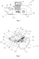
- a soil compactor is generally denoted by 10 .
- the soil compactor 10 that can be used, for example, for compacting asphalt material, soil, rubble or other bound or unbound soil material a rear carriage 12 having a cab 14 carried thereon for an operator.
- a drive unit is provided on the rear carriage 12, by means of which drive wheels 15 arranged on the rear carriage 12 can be driven in order to move the soil compactor 10 in the forward direction or in the reverse direction.
- a front carriage 18 constructed with a frame 16 is pivotably supported on the rear carriage 12 .
- the soil compactor 10 can be steered by pivoting the front carriage 18 about an approximately vertical axis with respect to the rear carriage 12 .
- On the frame 16 of the front end 18 is a compactor roller 20 by an in 2 shown roller axis of rotation W rotatably supported.
- the compactor roller 20 can itself be driven for rotation about the roller axis of rotation W, alternatively it can be carried on the frame 16 of the front end 18 so as to be essentially freely rotatable about the roller axis of rotation B.
- the compactor roller 20 rolls over the subsoil 26 to be compacted with an outer surface 22 of a roller shell 24 enclosing a roller interior 23.
- oscillation/vibration arrangement 28 In the roller interior 23 of the in 2 Compressor roller 20 shown in longitudinal section is provided with an oscillation/vibration arrangement, generally designated 28 . As described in detail below, the oscillation/vibration arrangement 28 can exert a force on the compactor roller 20 or the roller shell 24 thereof in order to thereby influence the compaction behavior.
- this force is directed essentially orthogonally to the roller axis of rotation W and the direction of the force rotates about the roller axis of rotation W, so that the compactor roller 20 is operated in a vibration mode in which, due to the rotating direction about the roller axis of rotation W
- the force acting on the compactor roller 20 periodically accelerates the compactor roller 20 upwards and downwards and thus periodically strikes the subsoil 22 to be compacted or is pressed against it.
- the force exerted on the compactor roller 20 acts tangentially or in the circumferential direction, so that the roller jacket 24 periodically Circumferentially about the roll axis of rotation W is accelerated back and forth and thus a walking effect arises in the compression mode.
- the oscillation/vibration arrangement 28 comprises two oscillation/vibration units 30, 32.
- Each of the oscillation/vibration units 30, 32 is driven by an oscillation/drive 34 for rotation about a respective oscillation/vibration axis of rotation D 1 or D 2 drivable.
- the oscillation/vibration drive 34 can have, for example, a hydraulic motor 36 which, via a belt drive mechanism 38, causes the two oscillation/vibration units 30, 32 to rotate about the respectively assigned oscillation/vibration axis of rotation D 1 or D 2 in the same direction of rotation and drives at the same speed.
- the first oscillation/vibration arrangement 30 comprises a first oscillation/vibration shaft 40 which, for example, is rotatably supported at its two axial end regions on carrier disks 42, 44 connected to an inner peripheral surface of the roll shell 24.
- the second oscillation/vibration unit 32 comprises a second oscillation/vibration shaft 46 rotatably carried on the two carrier disks 42, 44.
- first imbalance masses 50, 50' which are preferably constructed essentially identically to one another, are carried at an axial distance from one another.
- second oscillation/vibration shaft 46 of the second oscillation/vibration unit 32 two second unbalanced masses 52, 52', which are preferably essentially identical to one another, are carried at an axial distance from one another.
- the arrangement is such that each of the two oscillation/vibration units 30, 32 has an unbalanced mass 50, 50' or 52, 52' in the same axial area as the other of the two oscillation/vibration units 30 , 32.
- the two oscillation/vibration units 30, 32 are arranged in such a way that their respective oscillation/vibration axes of rotation D 1 , D 2 extend essentially parallel to the roller axis of rotation W and are also at the same distance from it. Furthermore, the two oscillation/vibration units 30, 32 and whose oscillation/vibration axes of rotation D 1 , D 2 are at an angular distance of about 180° with respect to the axis of rotation W of the roll, so that the two axes of oscillation/vibration of rotation D 1 , D 2 are diametrically opposite one another with respect to the axis of rotation W of the roll.
- first unbalanced masses 50, 50' and the second unbalanced masses 52, 52' of the two oscillation/vibration units 30, 32 are described in detail below, with due to the already mentioned mutually identical design of the respective unbalanced masses 50, 50' and 52, 52' only refers to the first unbalanced mass 50 of the first oscillation/vibration unit 30 or the second unbalanced mass 52 of the second oscillation/vibration unit 32.
- the first unbalanced mass 50 shown in an axial view and carried on the first oscillation/vibration shaft 40 comprises a first unbalanced mass part 54 which is non-rotatably connected to the first oscillation/vibration shaft 40, for example by screwing and/or by material connection.
- the first unbalanced mass part 54 has a first oscillation / vibration wave 40 fixed unbalanced mass element 56 and with the unbalanced mass element 56 firmly connected guide track element 58.
- Unbalanced mass element 56 and guide track element 58 delimit a receiving space 60 for a second unbalanced mass part 62 of first unbalanced mass 50 that can be moved with respect to first unbalanced mass part 54 of first unbalanced mass 50.
- the second unbalanced mass part 62 comprises a first rolling body 64 that is essentially cylindrical, i.e., roller-like in design, and that is acted upon radially outwards by the action of centrifugal force when the first unbalanced mass 50 is rotating and is pressed against a first guideway 66 that is provided on the guideway element 58 and is oriented radially inward is.
- the radially inward-oriented first guide track 66 has a substantially constant distance from the first oscillation/vibration axis of rotation D 1 in the circumferential direction, so that a radially inward-oriented guide track surface normal N 1 of the first guide track 66 is substantially radially downward Inside is oriented with respect to the first oscillation/vibration axis of rotation D 1 .
- the receiving space 60 can be closed off in the axial direction, for example by disk-like cover elements, in order to prevent the rolling body from falling out of the receiving space 60 in the axial direction. These cover elements thus provide part of the respective first imbalance mass part 54 and contribute to its mass or to its imbalance moment.
- the rolling body 64 that essentially provides the second mass part 62 can be moved between two end positions along the first guide track 66 in the receiving space 60 .
- the first rolling body 64 is positioned in its second end position, in which it is supported in the circumferential direction on the unbalanced mass element 56 and is positioned close to an unbalanced mass section 68 of the unbalanced mass element 56 .
- a large part of the mass of the unbalanced mass element 56 is provided in the unbalanced mass section 68, so that in 3 In the illustrated positioning of the second unbalanced mass part 62 in its second end position, the center of mass of the first unbalanced mass 50 is positioned essentially above the first oscillation/vibration axis of rotation D 1 and thus the centrifugal force acting in this state when the first unbalanced mass 50 rotates is directed essentially upwards .
- the second unbalanced mass part 62 After movement of the second unbalanced mass part 62 along the first guide track 66, the second unbalanced mass part 62 comes into its in 3 First end position shown with a dashed line, in which the first rolling body 64 of the second unbalanced mass part 62 is supported on a support section 70 of the unbalanced mass element 56 in the circumferential direction. Even in this condition, the in 3 Illustrated rotary positioning of the first unbalanced mass 50, the center of gravity of the same is essentially arranged above the first oscillation/vibration axis of rotation D 1 .
- the center of mass of the first unbalanced mass 50 has a smaller radial distance to the first oscillation/vibration axis of rotation D1, so that the in this state or in this rotational positioning of the first unbalanced mass 50 existing unbalance moment is less than an unbalance moment which the first unbalance mass 50 has when the second unbalance mass part 62 in its in 1 second end position shown above.
- the centrifugal force occurring when the second unbalanced mass part 62 is positioned in its second end position is lower than in a state in which the second mass part 62 is in its first end position supported in the circumferential direction by the unbalanced mass section 68 .
- the centers of mass M 11 and M 12 are in the circumferential direction on both sides of the radial line R, since when moving between the second end position and the first end position, the first unbalanced mass part 62 or its center of mass M 12 moves along the assigned Guide track 66 is moved about the first oscillation/vibration axis of rotation D 1 at an angle W 1 of less than 180°.
- each of the two distortions of the second unbalanced mass part 62 of the respective first unbalanced mass 50, 50' is therefore in the 3 In the rotational state shown, the center of mass of the unbalanced mass 50 or 50' is on the radial line R and above the first oscillation/vibration axis of rotation D 1 , but at a different radial distance from it, so that when the second unbalanced mass part 62 is positioned in its second end position, a greater unbalance moment of the respective first unbalanced mass 50 or 50' than when the second unbalanced mass part 62 is positioned in its second end position.
- the 4 shows the structure of the second unbalanced mass 52, which corresponds in principle to the structure of the first unbalanced mass 50.
- the second unbalanced mass 52 has a first unbalanced mass part 72 held non-rotatably on the second oscillation/vibration shaft 46 , which in turn is formed with an unbalanced mass element 74 and a guide track element 78 delimiting a receiving space 76 together with this.
- a second unbalanced mass part 82 of the second unbalanced mass 52 is accommodated in the receiving space 76 such that it can move in the circumferential direction about the second oscillation/vibration axis of rotation D 2 with respect to the first unbalanced mass part 72 .
- the second unbalanced mass part 82 of the second unbalanced mass 52 comprises two second rolling bodies 84, 86, for example identical to one another and also to the first rolling body 64 of the second unbalanced mass part 62 of the first unbalanced mass 50.
- the second rolling bodies 84, 86 can roll in the receiving space 76 along the second guide track 80 between the in 4
- the receiving space 76 can be closed off in the axial direction, for example by disk-like cover elements, in order to prevent the rolling body from falling out of the receiving space 76 in the axial direction.
- cover elements thus provide a part of the respective first imbalance mass part 72 and contribute to its mass or to its imbalance moment.
- the second unbalanced mass 52 Since a large part of the mass of the second unbalanced mass part 52 is arranged under the second oscillation/vibration axis of rotation D 2 and approximately in the same circumferential area, the second unbalanced mass 52 has a comparatively large unbalanced moment in this state, since the center of mass of the second unbalanced mass 52 is Mass distribution has a comparatively large radial distance from the second oscillation / vibration axis of rotation D 2 .
- the second unbalanced mass part 82 of the second unbalanced mass 52 is in its in 4 First end position shown above, a larger part of the mass of the second unbalanced mass 52 is moved upwards. As a result, in this state, the center of mass of the second unbalanced mass 52 or 52' is in 4
- the rotational positioning shown is essentially above the second oscillation/vibration axis of rotation D2 , but is at a smaller radial distance from it than when the second unbalanced mass part 82 is positioned in the second end position. This means that when the second mass part 82 is positioned in the first end position, the centrifugal force acting in the center of mass is smaller than when the second mass part 82 is positioned in the second end position.
- This switching behavior is also achieved with the respective second unbalanced mass 52 or 52' in that in both end positions of the second unbalanced mass part 82 a center of mass M 22 of the second unbalanced mass part 82 and a mass center M 21 of the first unbalanced mass part 72 are offset from one another in the circumferential direction and are therefore not lie on a common radial line intersecting the second oscillation/vibration axis of rotation D 2 , but rather lie on both sides of the radial line R which essentially corresponds to a vertical direction in this state of rotation.
- the second unbalanced mass part 82 of the second unbalanced mass 52 or 52' or its center of mass M 22 turns around moves the second oscillation/vibration axis of rotation D 2 at an angle W 2 of less than 180°.
- the angle W 2 is smaller than the angle W 1 in order to obtain the desired turning behavior.
- the first unbalanced mass 50 is the center of mass of the first unbalanced mass 50 is displaced radially, but experiences no movement in the circumferential direction with respect to the first unbalanced mass part 54, while the center of mass of the second unbalanced mass 52 is displaced radially on the one hand and on the other hand in the circumferential direction around the second oscillation/vibration axis of rotation D 2 at an angle of 180 ° relocated.
- the first unbalanced mass part 54 of the first unbalanced mass 50 is Unbalanced mass section 68 is designed with a larger volume and thus also greater mass than unbalanced mass section 88 of first unbalanced mass part 72 of second unbalanced mass 52. This compensates for the fact that second unbalanced mass part 82 of second unbalanced mass 52 has twice the mass of the second unbalanced mass part 62 of the first unbalanced mass 50.
- the center of mass of each of the unbalanced masses 50, 52 has a smaller radial distance to the respective oscillation/vibration axis of rotation D 1 , D 2 , so that the centrifugal force acting on the respective center of mass or represented by it in rotational operation will be lower, but the two centrifugal forces acting on the unbalanced masses 50, 52 are directed in the same way.
- the figure 5 shows the compactor roller 20 in an oscillating operation of the oscillation/vibration arrangement 28.
- the two oscillation/vibration units 30, 32 rotate about the respective associated oscillation/vibration axis of rotation D 1 or D 2 in the view of FIG figure 5 clockwise and at the same speed.
- the second unbalanced mass parts 62 or 82 of the unbalanced masses 50, 50', 52, 52' are in their respective second end position, so that the rolling bodies 64 or 84, 86 are supported in the circumferential direction on the respective unbalanced mass section 68 or 88 or by this be taken along for movement in the circumferential direction.
- the rolling bodies 64 or 84, 86 are supported radially outwards on the first guideway 66 or second guideway 80.
- rotational state is the center of gravity of the first unbalanced masses 50, 50 'in the height direction above the first oscillation / vibration axis of rotation D 1 , so that the first Imbalance masses 50, 50 'occurring centrifugal force F 1 is directed substantially vertically upwards.
- the center of mass lies vertically or in the vertical direction below the second oscillation/vibration axis of rotation D 2 , so that the centrifugal force F 2 occurring on the second unbalanced masses 52, 52' is directed essentially vertically downwards.
- In 6 are the two oscillation / vibration units 30, 32 shown in a rotational state in which, compared to the rotational state of the figure 5 , the direction of rotation has reversed.
- the oscillation/vibration units 30, 32 rotate counter-clockwise at the same speed.
- the second unbalanced mass parts 62 or 82 move in the respective receiving space 60 or 76 as a result of the rolling movement of the rolling bodies 64 or 84, 86 along the first guideway 66 or the second guideway 80 in the circumferential direction with respect to the respective first unbalanced mass part 54 or 72 that they reach the respective first end position.
- the second unbalanced mass parts 62 or 82 are supported in the circumferential direction on the respective support section 70 or 90 and are entrained by it for movement in the circumferential direction.
- the two centrifugal forces F 1 ', F 2 ' add up to form a total centrifugal force which is directed radially with respect to the axis of rotation W of the roll.
- the compactor roller 20 or the oscillation/vibration arrangement 28 thus works in vibration mode, in which, when the oscillation/vibration units 30, 32 rotate , the resulting total Centrifugal force rotates about the roller axis of rotation W and thus the compactor roller 20 is periodically accelerated upwards and downwards and correspondingly periodically loads the subsoil 26 to be compacted.
- the two second unbalanced mass parts 62, 82 differ in terms of their mass and thus the unbalanced moment provided in each case, but the first unbalanced mass parts 54, 72 also differ from one another in their mass and thus the unbalanced moment provided thereby.
- the first unbalanced mass part 54 of each first unbalanced mass 50, 50′ essentially corresponds to the unbalanced moment of the respective second unbalanced mass parts 82 of the second unbalanced masses 52, 52′ with regard to the unbalanced moment provided thereby.
- the first unbalanced mass parts 72 of the second unbalanced masses 52, 52′ essentially correspond to the unbalanced moment of the respective second unbalanced mass parts 62 of the first unbalanced masses 50, 50′ with regard to the unbalanced moments provided thereby.
- the extent of the change in the centrifugal force amounts during the transition from oscillating operation to vibration operation can be specified in a large range of values the change in speed made possible by this switching behavior and thus the frequency with which the compactor roller 20 is periodically loaded can also be freely specified in a large range of values.
- the structure described above can of course be varied in a wide variety of aspects without deviating from the functional principle and the structural principle.
- the oscillation / vibration units only one unbalanced mass or more than two unbalanced masses can be provided.
- each of the oscillation/vibration units has the same imbalance moment.
- the respective second unbalanced mass parts could also be designed differently.
- the second rolling bodies provided with the second unbalanced masses could have a different dimensioning or a different shape than the first rolling body provided with the respective first unbalanced masses.
- the different masses of the respective second unbalanced mass parts can also be achieved, for example, in that rolling bodies that are essentially of the same dimensions have different masses.
- the first rolling body to be provided with a lower mass can be designed as a hollow body for the first unbalanced masses, while a second rolling body to be provided for the respective second unbalanced masses can be designed as a solid rolling body and thus provided with a greater mass.
- the structure or the mass distribution of the various unbalanced masses can also be changed in comparison to the configuration shown in the figures and described above in that the first oscillation/vibration unit 30 or the unbalanced masses 50, 50' of the same have the centers of mass M 11 , M 12 of the two unbalanced mass parts 54, 62 in comparison to the in 3 arrangement shown are reversed in their position with respect to the radial line R, so that the center of mass M 11 of the first unbalanced mass part 54 in the rotational state shown lies to the right of the essentially vertically extending radial line R and in both end positions the center of mass M 12 of the second unbalanced mass part 62 lies to the left from the radial line R.
- the center of mass M 12 of the second unbalanced mass part 62 moves at an angle W 1 that is greater than 180° when moving between the two end positions.
- the centers of mass M 21 , M 22 of the two unbalanced mass parts 72 , 82 in the second oscillation/vibration unit 32 or the unbalanced masses 52 , 52 ′ can be different in comparison to the in 4 arrangement shown are reversed in their position with respect to the radial line R, so that the center of mass M 21 of the first unbalanced mass part 72 lies to the left of the essentially vertically extending radial line R in the rotational state shown, and the center of mass M 22 of the second unbalanced mass part 82 lies to the right of the radial line R in both end positions.
- the center of mass M 22 of the second unbalanced mass part 82 moves at an angle W 2 that is greater than 180° when moving between the two end positions.
- both angles W 1 , W 2 are greater than 180°, the angle W 2 is greater than the angle W 1 in order to achieve a turnover behavior that is suitable with regard to the imbalance moments to be set.
Landscapes
- Engineering & Computer Science (AREA)
- Structural Engineering (AREA)
- Civil Engineering (AREA)
- Life Sciences & Earth Sciences (AREA)
- Architecture (AREA)
- Environmental & Geological Engineering (AREA)
- General Life Sciences & Earth Sciences (AREA)
- Mining & Mineral Resources (AREA)
- Paleontology (AREA)
- Soil Sciences (AREA)
- General Engineering & Computer Science (AREA)
- Agronomy & Crop Science (AREA)
- Mechanical Engineering (AREA)
- Road Paving Machines (AREA)
- Investigation Of Foundation Soil And Reinforcement Of Foundation Soil By Compacting Or Drainage (AREA)
Priority Applications (1)
| Application Number | Priority Date | Filing Date | Title |
|---|---|---|---|
| EP23184354.1A EP4230796B1 (fr) | 2020-12-10 | 2021-11-05 | Rouleau compresseur pour un compacteur de sol |
Applications Claiming Priority (1)
| Application Number | Priority Date | Filing Date | Title |
|---|---|---|---|
| DE102020132973.3A DE102020132973A1 (de) | 2020-12-10 | 2020-12-10 | Verdichterwalze für einen Bodenverdichter |
Related Child Applications (2)
| Application Number | Title | Priority Date | Filing Date |
|---|---|---|---|
| EP23184354.1A Division EP4230796B1 (fr) | 2020-12-10 | 2021-11-05 | Rouleau compresseur pour un compacteur de sol |
| EP23184354.1A Division-Into EP4230796B1 (fr) | 2020-12-10 | 2021-11-05 | Rouleau compresseur pour un compacteur de sol |
Publications (3)
| Publication Number | Publication Date |
|---|---|
| EP4012099A2 true EP4012099A2 (fr) | 2022-06-15 |
| EP4012099A3 EP4012099A3 (fr) | 2022-07-06 |
| EP4012099B1 EP4012099B1 (fr) | 2023-08-16 |
Family
ID=78528783
Family Applications (2)
| Application Number | Title | Priority Date | Filing Date |
|---|---|---|---|
| EP23184354.1A Active EP4230796B1 (fr) | 2020-12-10 | 2021-11-05 | Rouleau compresseur pour un compacteur de sol |
| EP21206583.3A Active EP4012099B1 (fr) | 2020-12-10 | 2021-11-05 | Rouleau de compacteur pour un compacteur de sol |
Family Applications Before (1)
| Application Number | Title | Priority Date | Filing Date |
|---|---|---|---|
| EP23184354.1A Active EP4230796B1 (fr) | 2020-12-10 | 2021-11-05 | Rouleau compresseur pour un compacteur de sol |
Country Status (5)
| Country | Link |
|---|---|
| US (1) | US12410566B2 (fr) |
| EP (2) | EP4230796B1 (fr) |
| JP (1) | JP7297857B2 (fr) |
| CN (2) | CN114622536B (fr) |
| DE (1) | DE102020132973A1 (fr) |
Families Citing this family (2)
| Publication number | Priority date | Publication date | Assignee | Title |
|---|---|---|---|---|
| DE102020132973A1 (de) * | 2020-12-10 | 2022-06-15 | Hamm Ag | Verdichterwalze für einen Bodenverdichter |
| DE102024110799A1 (de) * | 2024-04-17 | 2025-10-23 | Bomag Gmbh | Schwingungserreger für eine Bodenverdichtungsmaschine und Bodenverdichtungsmaschine |
Citations (1)
| Publication number | Priority date | Publication date | Assignee | Title |
|---|---|---|---|---|
| JPH0223313A (ja) | 1988-07-13 | 1990-01-25 | Hitachi Ltd | 光走査装置及び走査レンズ |
Family Cites Families (19)
| Publication number | Priority date | Publication date | Assignee | Title |
|---|---|---|---|---|
| DE2140006B1 (de) * | 1971-08-10 | 1972-05-25 | Maschinenfabrik Buckau R Wolf Ag | Schwingungserreger |
| US3909147A (en) * | 1974-11-07 | 1975-09-30 | Raygo Inc | Variable amplitude vibration generator |
| SE426719B (sv) | 1980-12-03 | 1983-02-07 | Thurner Geodynamik Ab | Forfarande och anordning for packning av ett materialskikt |
| JPS58500290A (ja) * | 1980-12-03 | 1983-02-24 | ゲオデイナミツク エイチ ツルナ− エ−ビ− | 地盤の圧密化方法および圧密化装置 |
| JPH0136967Y2 (fr) | 1984-12-26 | 1989-11-09 | ||
| FR2639376A1 (fr) | 1988-11-24 | 1990-05-25 | Albaret Travaux Publics Sa | Engin compacteur vibrant a amplitude modifiable |
| JPH0554607A (ja) | 1991-06-12 | 1993-03-05 | Ricoh Co Ltd | 光デイスクシステム |
| JPH0554607U (ja) * | 1991-12-18 | 1993-07-23 | 株式会社小松エスト | 起振装置の振幅切換装置 |
| JP4555444B2 (ja) | 2000-08-17 | 2010-09-29 | 酒井重工業株式会社 | マカダム型振動ローラの油圧装置 |
| JP4746209B2 (ja) | 2001-07-09 | 2011-08-10 | 酒井重工業株式会社 | 振動機構及び振動ローラ |
| JP2003096713A (ja) | 2001-09-26 | 2003-04-03 | Sakai Heavy Ind Ltd | 振動ローラ |
| JP2004223313A (ja) | 2003-01-20 | 2004-08-12 | Sakai Heavy Ind Ltd | 振動機構及び振動ローラ |
| JP3799022B2 (ja) * | 2003-02-24 | 2006-07-19 | 酒井重工業株式会社 | 振動機構及び振動ローラ |
| DE102009055950A1 (de) * | 2009-11-27 | 2011-06-01 | Hamm Ag | Verdichtungsgerät, sowie Verfahren zum Verdichten von Böden |
| DE102012201443A1 (de) | 2012-02-01 | 2013-08-01 | Hamm Ag | Verdichterwalze für einen Bodenverdichter |
| DE102013020690A1 (de) | 2013-12-03 | 2015-06-03 | Bomag Gmbh | Schwingungserreger für einen Vibrationsverdichter sowie Baumaschine mit einem solchen Schwingungserreger |
| JP6401649B2 (ja) | 2015-03-31 | 2018-10-10 | 酒井重工業株式会社 | 起振軸 |
| US20170016184A1 (en) * | 2015-07-15 | 2017-01-19 | Caterpillar Paving Products Inc. | Vibratory Compactor Having Conventional and Oscillatory Vibrating Capability |
| DE102020132973A1 (de) * | 2020-12-10 | 2022-06-15 | Hamm Ag | Verdichterwalze für einen Bodenverdichter |
-
2020
- 2020-12-10 DE DE102020132973.3A patent/DE102020132973A1/de active Pending
-
2021
- 2021-11-05 EP EP23184354.1A patent/EP4230796B1/fr active Active
- 2021-11-05 EP EP21206583.3A patent/EP4012099B1/fr active Active
- 2021-12-08 US US17/545,172 patent/US12410566B2/en active Active
- 2021-12-09 JP JP2021200047A patent/JP7297857B2/ja active Active
- 2021-12-10 CN CN202111505398.0A patent/CN114622536B/zh active Active
- 2021-12-10 CN CN202123119211.1U patent/CN218757395U/zh not_active Withdrawn - After Issue
Patent Citations (1)
| Publication number | Priority date | Publication date | Assignee | Title |
|---|---|---|---|---|
| JPH0223313A (ja) | 1988-07-13 | 1990-01-25 | Hitachi Ltd | 光走査装置及び走査レンズ |
Also Published As
| Publication number | Publication date |
|---|---|
| CN114622536A (zh) | 2022-06-14 |
| US12410566B2 (en) | 2025-09-09 |
| EP4230796B1 (fr) | 2026-02-18 |
| JP2022092610A (ja) | 2022-06-22 |
| US20220186445A1 (en) | 2022-06-16 |
| CN218757395U (zh) | 2023-03-28 |
| EP4012099B1 (fr) | 2023-08-16 |
| DE102020132973A1 (de) | 2022-06-15 |
| EP4230796A3 (fr) | 2023-10-25 |
| JP7297857B2 (ja) | 2023-06-26 |
| EP4012099A3 (fr) | 2022-07-06 |
| EP4230796A2 (fr) | 2023-08-23 |
| CN114622536B (zh) | 2025-05-09 |
Similar Documents
| Publication | Publication Date | Title |
|---|---|---|
| EP2881516B1 (fr) | Compacteur routier | |
| EP2390416B1 (fr) | Dispositif de vibration pour appareil de compactage du sol et appareil de compactage du sol | |
| DE3413091C2 (fr) | ||
| EP4012099B1 (fr) | Rouleau de compacteur pour un compacteur de sol | |
| DE2633578C2 (de) | Vibrator mit verstellbarer Schwungmasse | |
| EP2172279A1 (fr) | Dispositif de production d'une oscillation circulaire ou d'une oscillation orientée dotée d'une amplitude d'oscillation ou d'une force d'excitation réglable en continu | |
| EP1305121B1 (fr) | Vibreur reglable | |
| DE3019015C2 (fr) | ||
| WO2015101407A1 (fr) | Bandage de compactage du sol, cylindre muni d'un tel bandage de compactage du sol, dispositif vibromoteur pour bandage de compactage du sol et procédé de compactage du sol | |
| EP3992364A1 (fr) | Procédé de compactage de matières asphaltiques | |
| DE3634157C2 (de) | Rüttelvorrichtung mit zu verändernder Schwingkraft | |
| EP0780164A2 (fr) | Vibrateur à action dirigée | |
| EP3450631B1 (fr) | Vibreur en profondeur avec une masse non équilibrée réglable | |
| DE2631826A1 (de) | Zentrifugalmuehle | |
| EP2732100B1 (fr) | Excitateur à balourd pour compacteur de sol | |
| EP3354796B1 (fr) | Rouleau compresseur | |
| EP1449965B1 (fr) | Vibreur pour compaction du sol | |
| DE10147957A1 (de) | Schwingungserreger für eine Bodenverdichtungsvorrichtung | |
| DE2001987A1 (de) | Bodenverdichtungsgeraet | |
| WO2018130262A1 (fr) | Rouleau de compactage du sol ainsi que procédé permettant de générer un modèle oscillatoire d'un rouleau de compactage du sol | |
| DE10148503C5 (de) | Falzapparat mit umfangsverstellbarem Zylinder | |
| DE102008008802B4 (de) | Bodenverdichtungsgerät mit einem Schwingungserreger | |
| EP4249678B1 (fr) | Procédé de fonctionnement d'un compacteur de sol et compacteur de sol | |
| DE1111107B (de) | Vibrationswalze zur Verdichtung von Boeden und sonstigen Schuettmassen | |
| EP0824971B1 (fr) | Générateur de vibrations |
Legal Events
| Date | Code | Title | Description |
|---|---|---|---|
| PUAI | Public reference made under article 153(3) epc to a published international application that has entered the european phase |
Free format text: ORIGINAL CODE: 0009012 |
|
| STAA | Information on the status of an ep patent application or granted ep patent |
Free format text: STATUS: REQUEST FOR EXAMINATION WAS MADE |
|
| PUAL | Search report despatched |
Free format text: ORIGINAL CODE: 0009013 |
|
| 17P | Request for examination filed |
Effective date: 20211105 |
|
| AK | Designated contracting states |
Kind code of ref document: A2 Designated state(s): AL AT BE BG CH CY CZ DE DK EE ES FI FR GB GR HR HU IE IS IT LI LT LU LV MC MK MT NL NO PL PT RO RS SE SI SK SM TR |
|
| AK | Designated contracting states |
Kind code of ref document: A3 Designated state(s): AL AT BE BG CH CY CZ DE DK EE ES FI FR GB GR HR HU IE IS IT LI LT LU LV MC MK MT NL NO PL PT RO RS SE SI SK SM TR |
|
| RIC1 | Information provided on ipc code assigned before grant |
Ipc: E01C 19/28 20060101AFI20220527BHEP |
|
| GRAP | Despatch of communication of intention to grant a patent |
Free format text: ORIGINAL CODE: EPIDOSNIGR1 |
|
| STAA | Information on the status of an ep patent application or granted ep patent |
Free format text: STATUS: GRANT OF PATENT IS INTENDED |
|
| INTG | Intention to grant announced |
Effective date: 20230417 |
|
| GRAS | Grant fee paid |
Free format text: ORIGINAL CODE: EPIDOSNIGR3 |
|
| GRAA | (expected) grant |
Free format text: ORIGINAL CODE: 0009210 |
|
| STAA | Information on the status of an ep patent application or granted ep patent |
Free format text: STATUS: THE PATENT HAS BEEN GRANTED |
|
| AK | Designated contracting states |
Kind code of ref document: B1 Designated state(s): AL AT BE BG CH CY CZ DE DK EE ES FI FR GB GR HR HU IE IS IT LI LT LU LV MC MK MT NL NO PL PT RO RS SE SI SK SM TR |
|
| REG | Reference to a national code |
Ref country code: CH Ref legal event code: EP |
|
| REG | Reference to a national code |
Ref country code: DE Ref legal event code: R096 Ref document number: 502021001259 Country of ref document: DE |
|
| REG | Reference to a national code |
Ref country code: IE Ref legal event code: FG4D Free format text: LANGUAGE OF EP DOCUMENT: GERMAN |
|
| REG | Reference to a national code |
Ref country code: SE Ref legal event code: TRGR |
|
| REG | Reference to a national code |
Ref country code: LT Ref legal event code: MG9D |
|
| REG | Reference to a national code |
Ref country code: NL Ref legal event code: MP Effective date: 20230816 |
|
| PG25 | Lapsed in a contracting state [announced via postgrant information from national office to epo] |
Ref country code: GR Free format text: LAPSE BECAUSE OF FAILURE TO SUBMIT A TRANSLATION OF THE DESCRIPTION OR TO PAY THE FEE WITHIN THE PRESCRIBED TIME-LIMIT Effective date: 20231117 |
|
| PG25 | Lapsed in a contracting state [announced via postgrant information from national office to epo] |
Ref country code: IS Free format text: LAPSE BECAUSE OF FAILURE TO SUBMIT A TRANSLATION OF THE DESCRIPTION OR TO PAY THE FEE WITHIN THE PRESCRIBED TIME-LIMIT Effective date: 20231216 |
|
| PG25 | Lapsed in a contracting state [announced via postgrant information from national office to epo] |
Ref country code: RS Free format text: LAPSE BECAUSE OF FAILURE TO SUBMIT A TRANSLATION OF THE DESCRIPTION OR TO PAY THE FEE WITHIN THE PRESCRIBED TIME-LIMIT Effective date: 20230816 Ref country code: PT Free format text: LAPSE BECAUSE OF FAILURE TO SUBMIT A TRANSLATION OF THE DESCRIPTION OR TO PAY THE FEE WITHIN THE PRESCRIBED TIME-LIMIT Effective date: 20231218 Ref country code: NO Free format text: LAPSE BECAUSE OF FAILURE TO SUBMIT A TRANSLATION OF THE DESCRIPTION OR TO PAY THE FEE WITHIN THE PRESCRIBED TIME-LIMIT Effective date: 20231116 Ref country code: NL Free format text: LAPSE BECAUSE OF FAILURE TO SUBMIT A TRANSLATION OF THE DESCRIPTION OR TO PAY THE FEE WITHIN THE PRESCRIBED TIME-LIMIT Effective date: 20230816 Ref country code: LV Free format text: LAPSE BECAUSE OF FAILURE TO SUBMIT A TRANSLATION OF THE DESCRIPTION OR TO PAY THE FEE WITHIN THE PRESCRIBED TIME-LIMIT Effective date: 20230816 Ref country code: LT Free format text: LAPSE BECAUSE OF FAILURE TO SUBMIT A TRANSLATION OF THE DESCRIPTION OR TO PAY THE FEE WITHIN THE PRESCRIBED TIME-LIMIT Effective date: 20230816 Ref country code: IS Free format text: LAPSE BECAUSE OF FAILURE TO SUBMIT A TRANSLATION OF THE DESCRIPTION OR TO PAY THE FEE WITHIN THE PRESCRIBED TIME-LIMIT Effective date: 20231216 Ref country code: HR Free format text: LAPSE BECAUSE OF FAILURE TO SUBMIT A TRANSLATION OF THE DESCRIPTION OR TO PAY THE FEE WITHIN THE PRESCRIBED TIME-LIMIT Effective date: 20230816 Ref country code: GR Free format text: LAPSE BECAUSE OF FAILURE TO SUBMIT A TRANSLATION OF THE DESCRIPTION OR TO PAY THE FEE WITHIN THE PRESCRIBED TIME-LIMIT Effective date: 20231117 Ref country code: FI Free format text: LAPSE BECAUSE OF FAILURE TO SUBMIT A TRANSLATION OF THE DESCRIPTION OR TO PAY THE FEE WITHIN THE PRESCRIBED TIME-LIMIT Effective date: 20230816 |
|
| PG25 | Lapsed in a contracting state [announced via postgrant information from national office to epo] |
Ref country code: PL Free format text: LAPSE BECAUSE OF FAILURE TO SUBMIT A TRANSLATION OF THE DESCRIPTION OR TO PAY THE FEE WITHIN THE PRESCRIBED TIME-LIMIT Effective date: 20230816 |
|
| PG25 | Lapsed in a contracting state [announced via postgrant information from national office to epo] |
Ref country code: ES Free format text: LAPSE BECAUSE OF FAILURE TO SUBMIT A TRANSLATION OF THE DESCRIPTION OR TO PAY THE FEE WITHIN THE PRESCRIBED TIME-LIMIT Effective date: 20230816 |
|
| PG25 | Lapsed in a contracting state [announced via postgrant information from national office to epo] |
Ref country code: SM Free format text: LAPSE BECAUSE OF FAILURE TO SUBMIT A TRANSLATION OF THE DESCRIPTION OR TO PAY THE FEE WITHIN THE PRESCRIBED TIME-LIMIT Effective date: 20230816 Ref country code: RO Free format text: LAPSE BECAUSE OF FAILURE TO SUBMIT A TRANSLATION OF THE DESCRIPTION OR TO PAY THE FEE WITHIN THE PRESCRIBED TIME-LIMIT Effective date: 20230816 Ref country code: ES Free format text: LAPSE BECAUSE OF FAILURE TO SUBMIT A TRANSLATION OF THE DESCRIPTION OR TO PAY THE FEE WITHIN THE PRESCRIBED TIME-LIMIT Effective date: 20230816 Ref country code: EE Free format text: LAPSE BECAUSE OF FAILURE TO SUBMIT A TRANSLATION OF THE DESCRIPTION OR TO PAY THE FEE WITHIN THE PRESCRIBED TIME-LIMIT Effective date: 20230816 Ref country code: DK Free format text: LAPSE BECAUSE OF FAILURE TO SUBMIT A TRANSLATION OF THE DESCRIPTION OR TO PAY THE FEE WITHIN THE PRESCRIBED TIME-LIMIT Effective date: 20230816 Ref country code: SK Free format text: LAPSE BECAUSE OF FAILURE TO SUBMIT A TRANSLATION OF THE DESCRIPTION OR TO PAY THE FEE WITHIN THE PRESCRIBED TIME-LIMIT Effective date: 20230816 |
|
| REG | Reference to a national code |
Ref country code: DE Ref legal event code: R097 Ref document number: 502021001259 Country of ref document: DE |
|
| PLBE | No opposition filed within time limit |
Free format text: ORIGINAL CODE: 0009261 |
|
| STAA | Information on the status of an ep patent application or granted ep patent |
Free format text: STATUS: NO OPPOSITION FILED WITHIN TIME LIMIT |
|
| PG25 | Lapsed in a contracting state [announced via postgrant information from national office to epo] |
Ref country code: MC Free format text: LAPSE BECAUSE OF FAILURE TO SUBMIT A TRANSLATION OF THE DESCRIPTION OR TO PAY THE FEE WITHIN THE PRESCRIBED TIME-LIMIT Effective date: 20230816 |
|
| PG25 | Lapsed in a contracting state [announced via postgrant information from national office to epo] |
Ref country code: LU Free format text: LAPSE BECAUSE OF NON-PAYMENT OF DUE FEES Effective date: 20231105 |
|
| 26N | No opposition filed |
Effective date: 20240517 |
|
| PG25 | Lapsed in a contracting state [announced via postgrant information from national office to epo] |
Ref country code: MC Free format text: LAPSE BECAUSE OF FAILURE TO SUBMIT A TRANSLATION OF THE DESCRIPTION OR TO PAY THE FEE WITHIN THE PRESCRIBED TIME-LIMIT Effective date: 20230816 Ref country code: LU Free format text: LAPSE BECAUSE OF NON-PAYMENT OF DUE FEES Effective date: 20231105 Ref country code: IT Free format text: LAPSE BECAUSE OF FAILURE TO SUBMIT A TRANSLATION OF THE DESCRIPTION OR TO PAY THE FEE WITHIN THE PRESCRIBED TIME-LIMIT Effective date: 20230816 Ref country code: SI Free format text: LAPSE BECAUSE OF FAILURE TO SUBMIT A TRANSLATION OF THE DESCRIPTION OR TO PAY THE FEE WITHIN THE PRESCRIBED TIME-LIMIT Effective date: 20230816 |
|
| REG | Reference to a national code |
Ref country code: BE Ref legal event code: MM Effective date: 20231130 |
|
| REG | Reference to a national code |
Ref country code: IE Ref legal event code: MM4A |
|
| PG25 | Lapsed in a contracting state [announced via postgrant information from national office to epo] |
Ref country code: IE Free format text: LAPSE BECAUSE OF NON-PAYMENT OF DUE FEES Effective date: 20231105 |
|
| PG25 | Lapsed in a contracting state [announced via postgrant information from national office to epo] |
Ref country code: BE Free format text: LAPSE BECAUSE OF NON-PAYMENT OF DUE FEES Effective date: 20231130 |
|
| PG25 | Lapsed in a contracting state [announced via postgrant information from national office to epo] |
Ref country code: FR Free format text: LAPSE BECAUSE OF NON-PAYMENT OF DUE FEES Effective date: 20231130 |
|
| PG25 | Lapsed in a contracting state [announced via postgrant information from national office to epo] |
Ref country code: IE Free format text: LAPSE BECAUSE OF NON-PAYMENT OF DUE FEES Effective date: 20231105 Ref country code: FR Free format text: LAPSE BECAUSE OF NON-PAYMENT OF DUE FEES Effective date: 20231130 Ref country code: BE Free format text: LAPSE BECAUSE OF NON-PAYMENT OF DUE FEES Effective date: 20231130 |
|
| PG25 | Lapsed in a contracting state [announced via postgrant information from national office to epo] |
Ref country code: BG Free format text: LAPSE BECAUSE OF FAILURE TO SUBMIT A TRANSLATION OF THE DESCRIPTION OR TO PAY THE FEE WITHIN THE PRESCRIBED TIME-LIMIT Effective date: 20230816 |
|
| PG25 | Lapsed in a contracting state [announced via postgrant information from national office to epo] |
Ref country code: BG Free format text: LAPSE BECAUSE OF FAILURE TO SUBMIT A TRANSLATION OF THE DESCRIPTION OR TO PAY THE FEE WITHIN THE PRESCRIBED TIME-LIMIT Effective date: 20230816 |
|
| REG | Reference to a national code |
Ref country code: CH Ref legal event code: PL |
|
| REG | Reference to a national code |
Ref country code: CH Ref legal event code: PL |
|
| PG25 | Lapsed in a contracting state [announced via postgrant information from national office to epo] |
Ref country code: CH Free format text: LAPSE BECAUSE OF NON-PAYMENT OF DUE FEES Effective date: 20241130 |
|
| PG25 | Lapsed in a contracting state [announced via postgrant information from national office to epo] |
Ref country code: CY Free format text: LAPSE BECAUSE OF FAILURE TO SUBMIT A TRANSLATION OF THE DESCRIPTION OR TO PAY THE FEE WITHIN THE PRESCRIBED TIME-LIMIT; INVALID AB INITIO Effective date: 20211105 |
|
| PG25 | Lapsed in a contracting state [announced via postgrant information from national office to epo] |
Ref country code: TR Free format text: LAPSE BECAUSE OF FAILURE TO SUBMIT A TRANSLATION OF THE DESCRIPTION OR TO PAY THE FEE WITHIN THE PRESCRIBED TIME-LIMIT Effective date: 20230816 |
|
| PGFP | Annual fee paid to national office [announced via postgrant information from national office to epo] |
Ref country code: DE Payment date: 20251119 Year of fee payment: 5 |
|
| PGFP | Annual fee paid to national office [announced via postgrant information from national office to epo] |
Ref country code: AT Payment date: 20260113 Year of fee payment: 5 |
|
| PGFP | Annual fee paid to national office [announced via postgrant information from national office to epo] |
Ref country code: SE Payment date: 20251119 Year of fee payment: 5 |
|
| PGFP | Annual fee paid to national office [announced via postgrant information from national office to epo] |
Ref country code: CZ Payment date: 20251029 Year of fee payment: 5 |
|
| PG25 | Lapsed in a contracting state [announced via postgrant information from national office to epo] |
Ref country code: HU Free format text: LAPSE BECAUSE OF FAILURE TO SUBMIT A TRANSLATION OF THE DESCRIPTION OR TO PAY THE FEE WITHIN THE PRESCRIBED TIME-LIMIT; INVALID AB INITIO Effective date: 20211105 |