EP4012126B1 - Vakuumreiniger-vorrichtung für reinigung der kanalisation - Google Patents
Vakuumreiniger-vorrichtung für reinigung der kanalisation Download PDFInfo
- Publication number
- EP4012126B1 EP4012126B1 EP20306532.1A EP20306532A EP4012126B1 EP 4012126 B1 EP4012126 B1 EP 4012126B1 EP 20306532 A EP20306532 A EP 20306532A EP 4012126 B1 EP4012126 B1 EP 4012126B1
- Authority
- EP
- European Patent Office
- Prior art keywords
- suction
- cleaning
- reel
- tank
- pipe
- Prior art date
- Legal status (The legal status is an assumption and is not a legal conclusion. Google has not performed a legal analysis and makes no representation as to the accuracy of the status listed.)
- Active
Links
Images



Classifications
-
- E—FIXED CONSTRUCTIONS
- E03—WATER SUPPLY; SEWERAGE
- E03F—SEWERS; CESSPOOLS
- E03F7/00—Other installations or implements for operating sewer systems, e.g. for preventing or indicating stoppage; Emptying cesspools
- E03F7/10—Wheeled apparatus for emptying sewers or cesspools
Definitions
- the present invention relates to a hydro-cleaning device, that is to say a device for carrying out pumping of effluents, in particular in septic tanks or in sewers.
- Devices of this type which exist on the market generally comprise a suction cistern, a suction pipe and pumping means making it possible to pump the effluents towards the suction cistern by means of the suction pipe.
- Such a device can typically be mounted on a wheeled chassis, this chassis possibly taking the form of a trailer intended to be hitched to a towing vehicle, or else forming part of a self-propelled vehicle.
- Such a hydro-cleaning device must be driven as close as possible to the site on which one wishes to carry out the pumping operations, the last meters towards the pumping zone being crossed by unrolling the suction pipe from a reel integral with the frame. or the suction tank of the device.
- a hydro-cleaning apparatus comprising a frame, a suction tank mounted on this frame, a suction pipe, means for pumping effluents by means of this pipe towards the cistern, a suction reel for storing this suction pipe, this suction reel being rotatably mounted about a substantially vertical axis, between said frame and said suction tank.
- the reel extends in a substantially horizontal plane, and can be placed between the chassis and the suction tank, that is to say in a zone which does not increase not the size of the hydro-cleaning vehicle.
- This vehicle can thus go into areas with difficult access, in particular in private homes to carry out septic tank or sewer pumping operations, which can be hindered for example by relatively low tree branches, or by other obstacles making access to these areas complicated for larger vehicles.
- this suction reel which allows the turns of the suction pipe to remain in a substantially horizontal plane, makes it possible to limit or even eliminate the pressure drops of the pumped effluents, which can be observed in conventional devices. where the winding of the suction pipe is done around a substantially horizontal axis, and where consequently each turn induces a pressure drop on pumping.
- the present invention also relates to a hydro-cleaning trailer, equipped with an apparatus in accordance with the above: such a trailer can be hitched to a tractor vehicle, in order to be driven over the pumping areas.
- the present invention also relates to a self-propelled hydrocleaning vehicle, equipped with an apparatus in accordance with the foregoing: such a vehicle is completely autonomous, both in terms of pumping and movement.
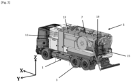
- an XYZ reference has been shown, in which the horizontal axis X is parallel to the longitudinal direction of the self-propelled vehicle according to the invention, the horizontal axis Y is perpendicular to this direction, and the axis Z is vertical.
- horizontal designates a direction parallel to the XY plane
- vertical a direction parallel to the Z axis
- front and “rear” must be understood with respect to the direction of the arrow l X axis, this arrow pointing to the front of the device.
- FIG. 1 , 2 , And 3 on which there is shown a self-propelled vehicle according to the invention, comprising a frame 1 mounted on axles provided with wheels 3, and supporting a hydro-cleaning device according to the invention 5.
- This hydro-cleaning device 5 comprises a suction tank 7, a suction pipe 9 and pumping means, not shown, located in a compartment machines 11 located at the front of the tank 7, making it possible to suck in the pipe 9 effluents such as sludge or waste water towards the interior of the suction tank 7.
- this suction pipe 9 can typically have a diameter of 65 to 100 mm, and be provided at its end with a connector allowing it to be connected to pumping accessories (rigid suction pipe for example ).
- the hydro-cleaning device according to the invention can also optionally comprise a high-pressure cleaning device, comprising a high-pressure pump not visible in these figures, but located in the area of the machines 11, and a high-pressure cleaning tank 13 located in front of the suction tank 7, which can contain a cleaning liquid such as water, and generally has a lower volume than that of the suction tank 7.
- a high-pressure cleaning device comprising a high-pressure pump not visible in these figures, but located in the area of the machines 11, and a high-pressure cleaning tank 13 located in front of the suction tank 7, which can contain a cleaning liquid such as water, and generally has a lower volume than that of the suction tank 7.
- this high-pressure cleaning device also comprises a hydraulically motorized reel 15 around which a high-pressure cleaning hose (not shown) is wound, this winding taking place around a substantially horizontal axis.
- the diameter of the high pressure cleaning pipe is smaller than that of the suction pipe 9: this diameter can typically be of the order of % inch or 1 inch.
- the high pressure reel 15 comprises a support 19 pivotally mounted on the suction tank between a folded position visible on the figure 1 , and a deployed position, visible on the figure 2 , And 3 , around a substantially vertical axis, that is to say substantially parallel to the Z axis.
- This support 19 can typically be made of mechanically welded metal alloy.
- the support 19 comprises a frame 21 provided with rollers, through which passes the suction pipe 9: during the rotational movement of the support 19 between its folded position and its deployed position, this frame 21 drives the suction pipe 9.
- the hydrocleaning device comprises a suction reel 23, around which the suction pipe 9 is wound, this reel being rotatably mounted on the frame 1 about a substantially vertical axis, c i.e. substantially parallel to the Z axis.
- Means for motorizing the hub 25 of the suction reel 23 are provided, so as to allow rotational movement of this reel without manual intervention.
- These motorization means can comprise a hydraulic or electric motor in direct or reduced drive with the reel 23.
- the suction cistern 7 and the suction pipe 9 make it possible to suck up effluents (sludge, waste water, etc.) originating for example from septic tanks or manholes.
- effluents sludge, waste water, etc.
- the hydro-cleaning device according to the invention is brought closer to the point of intervention.
- the means for motorizing the reel of the suction pipe 23 are activated, so as to allow the end of the suction pipe 9 to be driven to the suction point. .
- the support 19 is pivoted around its vertical axis, from its folded position ( figure 1 ) to its deployed position ( figure 2 And 3 ).
- the end of the suction pipe 9 can be brought as close as possible to the suction zone, without excessive effort.
- the pumping operations are then carried out, by starting the suction pump located in the machine part 11 of the hydro-cleaning apparatus according to the invention.
- the effluent suction operation can be supplemented with a high-pressure cleaning operation by means of the high-pressure cleaning hose (not shown), wound around the high-pressure reel 15: to do this, this high-pressure hose is unrolled and its end is brought to the area where the cleaning operations are to be carried out.
- the high-pressure cleaning pump located in the machine zone 11 is then started, which makes it possible to project water under high pressure from the high-pressure tank 13 against the surfaces to be cleaned.
- the high pressure cleaning hose is wound around the high pressure reel 15, then the support 19 is folded down towards its folded position against the rear of the suction tank 7.
- the arrangement of the suction reel 23 and the suction pipe 9 horizontally on the frame 1 is under the suction tank 7, makes it possible to obtain a particularly compactness of the hydro-cleaning device: this reel and this hose do not increase the external size of the device, which makes it particularly agile to intervene in areas that are difficult to access, for example where there are lower branches.
- the invention therefore makes it possible to obtain a device, and if necessary a trailer or a self-propelled vehicle equipped with such a device, which is particularly suitable for interventions in private homes (emptying of septic tanks in particular), where the accesses are often difficult.
- the horizontal arrangement of the reel 23 makes it possible to eliminate pressure losses in the turns of the suction pipe 9, and therefore to use a suction pump of lesser power, with equal suction.
- the optional guide means provided by the support 19, the frame 21 and, where appropriate, by the telescopic arm, greatly facilitate the manipulations of the operator to lead the end of the suction pipe 9 with precision towards the area of aspiration.
Landscapes
- Health & Medical Sciences (AREA)
- Life Sciences & Earth Sciences (AREA)
- Engineering & Computer Science (AREA)
- Hydrology & Water Resources (AREA)
- Public Health (AREA)
- Water Supply & Treatment (AREA)
- Cleaning In General (AREA)
- Sewage (AREA)
Claims (8)
- Saug-Spüleinrichtung, umfassend ein Gestell (1), einen Saugtank (7), der auf diesem Gestell (1) montiert ist, einen Saugschlauch (9), Mittel zum Pumpen von Abwässern anhand dieses Schlauches (9) zum Tank (7), eine Saughaspel (23) zum Verstauen dieses Saugschlauches (9), wobei diese Saughaspel (23) um eine im Wesentlichen vertikale Achse drehend montiert ist,
dadurch gekennzeichnet, dass
diese Saughaspel (23) zwischen dem Gestell (1) und dem Saugtank (7) montiert ist. - Einrichtung nach Anspruch 1, wobei die Saughaspel (23) motorisiert ist.
- Einrichtung nach einem der Ansprüche 1 oder 2, weiter umfassend eine Hochdruck-Reinigungsvorrichtung, umfassend einen Reinigungstank (13), der auf dem Gestell (5) montiert ist, einen Hochdruck-Reinigungsschlauch, Hochdruck-Pumpmittel für die Reinigungsflüssigkeit aus dem Reinigungstank (13) zum Reinigungsschlauch, eine Reinigungshaspel (15) zum Verstauen dieses Hochdruck-Reinigungsschlauches, wobei diese Reinigungshaspel (15) um eine im Wesentlichen horizontale Achse drehend auf einem Träger (19) montiert ist, der selbst zwischen einer eingefahrenen Position und einer ausgefahrenen Position um eine im Wesentlichen vertikale Achse drehend auf dem Saugtank (7) montiert ist.
- Einrichtung nach Anspruch 3, wobei der Träger (19) in seinem unteren Teil Führungsmittel (21) für den Saugschlauch (9) beinhaltet.
- Einrichtung nach Anspruch 4, wobei die Führungsmittel einen Rahmen (21) umfassen, der mit Drehrollen versehen ist.
- Einrichtung nach einem der Ansprüche 4 oder 5, wobei die Führungsmittel einen Teleskoparm umfassen.
- Saug-Spülanhänger, der mit einer Einrichtung nach einem der vorstehenden Ansprüche ausgerüstet ist.
- Saug-Spülkraftfahrzeug, das mit einer Einrichtung nach einem der Ansprüche 1 bis 6 ausgerüstet ist.
Priority Applications (1)
| Application Number | Priority Date | Filing Date | Title |
|---|---|---|---|
| EP20306532.1A EP4012126B1 (de) | 2020-12-10 | 2020-12-10 | Vakuumreiniger-vorrichtung für reinigung der kanalisation |
Applications Claiming Priority (1)
| Application Number | Priority Date | Filing Date | Title |
|---|---|---|---|
| EP20306532.1A EP4012126B1 (de) | 2020-12-10 | 2020-12-10 | Vakuumreiniger-vorrichtung für reinigung der kanalisation |
Publications (3)
| Publication Number | Publication Date |
|---|---|
| EP4012126A1 EP4012126A1 (de) | 2022-06-15 |
| EP4012126B1 true EP4012126B1 (de) | 2023-07-19 |
| EP4012126C0 EP4012126C0 (de) | 2023-07-19 |
Family
ID=74175579
Family Applications (1)
| Application Number | Title | Priority Date | Filing Date |
|---|---|---|---|
| EP20306532.1A Active EP4012126B1 (de) | 2020-12-10 | 2020-12-10 | Vakuumreiniger-vorrichtung für reinigung der kanalisation |
Country Status (1)
| Country | Link |
|---|---|
| EP (1) | EP4012126B1 (de) |
Family Cites Families (3)
| Publication number | Priority date | Publication date | Assignee | Title |
|---|---|---|---|---|
| DE1082860B (de) * | 1957-10-29 | 1960-06-02 | Paul Kahle Rohrleitungsbau G M | Schlammsaugewagen |
| SE8803405D0 (sv) * | 1988-09-27 | 1988-09-27 | Bo Larsson | Sett och anordning for bortforsel och rening av slam och avloppsvatten |
| DK2283938T3 (da) * | 2009-08-06 | 2013-11-11 | Karl Wiedemann | Indretning til rensning af kanaler |
-
2020
- 2020-12-10 EP EP20306532.1A patent/EP4012126B1/de active Active
Also Published As
| Publication number | Publication date |
|---|---|
| EP4012126C0 (de) | 2023-07-19 |
| EP4012126A1 (de) | 2022-06-15 |
Similar Documents
| Publication | Publication Date | Title |
|---|---|---|
| EP2458099B1 (de) | Automatische Auf- und Abrollvorrichtung für einen Hochdruckreinigungsschlauch, der mit einem Ansaugrohr eines kombinierten Rohrreinigungsfahrzeugs verbunden ist | |
| EP2240653B1 (de) | Vorrichtung zur reinigung einer untergetauchten fläche mit einer bürstenvorrichtung, die durch glieder zum antrieb der vorrichtung auf der untergetauchten fläche angetrieben wird | |
| FR3042808B1 (fr) | Appareil nettoyeur de piscine a dispositif de franchissement d'obstacle | |
| CA2987680A1 (fr) | Robot de nettoyage de piscine autonome | |
| FR2544296A1 (fr) | Enrouleur portable pour tuyauterie souple, notamment pour vehicules automobiles, caravanes, autobus, bateaux, terrasses et petits jardins | |
| EP3362619A1 (de) | Vorrichtung zur extraktion eines schwimmbeckenreinigers | |
| US7216666B2 (en) | Device for reeling-in a hose | |
| EP4012126A1 (de) | Vakuumreiniger-vorrichtung für reinigung der kanalisation | |
| FR2640314A1 (fr) | Ensemble de bobines de cable et de canalisation souple pour machine de forage | |
| FR2973212A3 (fr) | Dispositif pour l'elimination des eaux residuaires pour wc chimiques de camping-cars ou de caravanes | |
| FR2584435A1 (fr) | Engin de terrassement destine notamment aux fouilles d'intervention de petites dimensions. | |
| FR2654898A1 (fr) | Taille vegetaux a balancier. | |
| EP0592326A1 (de) | Baggergerät zum Graben von Tiefgräben mit Frästrommeln | |
| EP0185402A1 (de) | Verfahren zum Herstellen eines Betonpfahles und Vorrichtung zur Anwendung des Verfahrens | |
| FR2514605A1 (fr) | Installation pour le brassage, l'homogeneisation, et l'epandage de liquides charges | |
| FR2461088A1 (fr) | Dispositif de forage pour effectuer des prelevements de carottes dans le sol, et douille de carottage correspondante | |
| FR2523617A1 (fr) | Installation de vidange, notamment pour sanitaires d'avion | |
| FR3084900A1 (fr) | Dispositif et procede d'enroulement d'une couverture de protection pour bassin | |
| EP2428623B1 (de) | Mobile Müllsammelleinheit, und Verfahren für den Einsatz dieser Einheit | |
| FR2828482A3 (fr) | Enrouleur-devideur | |
| FR3078692A1 (fr) | Dispositif formant un devidoir d’une pluralite de tuyaux flexibles a derouler et connecter successivement les uns aux autres, procedes de fonctionnement associes | |
| EP1382749B1 (de) | Strassenfahrzeug mit Waschstruktur | |
| FR2510353A1 (fr) | Arroseur automatique auto-entraine | |
| FR2535701A1 (fr) | Dispositif d'animation d'un element de manutention et ou de chargement en particulier applicable a un dispositif d'extraction et de transfert de liquide | |
| EP0750702B1 (de) | Baggerlader |
Legal Events
| Date | Code | Title | Description |
|---|---|---|---|
| PUAI | Public reference made under article 153(3) epc to a published international application that has entered the european phase |
Free format text: ORIGINAL CODE: 0009012 |
|
| STAA | Information on the status of an ep patent application or granted ep patent |
Free format text: STATUS: THE APPLICATION HAS BEEN PUBLISHED |
|
| AK | Designated contracting states |
Kind code of ref document: A1 Designated state(s): AL AT BE BG CH CY CZ DE DK EE ES FI FR GB GR HR HU IE IS IT LI LT LU LV MC MK MT NL NO PL PT RO RS SE SI SK SM TR |
|
| STAA | Information on the status of an ep patent application or granted ep patent |
Free format text: STATUS: REQUEST FOR EXAMINATION WAS MADE |
|
| 17P | Request for examination filed |
Effective date: 20220915 |
|
| RBV | Designated contracting states (corrected) |
Designated state(s): AL AT BE BG CH CY CZ DE DK EE ES FI FR GB GR HR HU IE IS IT LI LT LU LV MC MK MT NL NO PL PT RO RS SE SI SK SM TR |
|
| GRAP | Despatch of communication of intention to grant a patent |
Free format text: ORIGINAL CODE: EPIDOSNIGR1 |
|
| STAA | Information on the status of an ep patent application or granted ep patent |
Free format text: STATUS: GRANT OF PATENT IS INTENDED |
|
| INTG | Intention to grant announced |
Effective date: 20230203 |
|
| GRAS | Grant fee paid |
Free format text: ORIGINAL CODE: EPIDOSNIGR3 |
|
| GRAA | (expected) grant |
Free format text: ORIGINAL CODE: 0009210 |
|
| STAA | Information on the status of an ep patent application or granted ep patent |
Free format text: STATUS: THE PATENT HAS BEEN GRANTED |
|
| RIN1 | Information on inventor provided before grant (corrected) |
Inventor name: AVICE, JEAN-MICHEL |
|
| AK | Designated contracting states |
Kind code of ref document: B1 Designated state(s): AL AT BE BG CH CY CZ DE DK EE ES FI FR GB GR HR HU IE IS IT LI LT LU LV MC MK MT NL NO PL PT RO RS SE SI SK SM TR |
|
| REG | Reference to a national code |
Ref country code: GB Ref legal event code: FG4D Free format text: NOT ENGLISH |
|
| REG | Reference to a national code |
Ref country code: CH Ref legal event code: EP |
|
| REG | Reference to a national code |
Ref country code: DE Ref legal event code: R096 Ref document number: 602020014025 Country of ref document: DE |
|
| REG | Reference to a national code |
Ref country code: IE Ref legal event code: FG4D Free format text: LANGUAGE OF EP DOCUMENT: FRENCH |
|
| U01 | Request for unitary effect filed |
Effective date: 20230817 |
|
| U07 | Unitary effect registered |
Designated state(s): AT BE BG DE DK EE FI FR IT LT LU LV MT NL PT SE SI Effective date: 20230824 |
|
| REG | Reference to a national code |
Ref country code: LT Ref legal event code: MG9D |
|
| PG25 | Lapsed in a contracting state [announced via postgrant information from national office to epo] |
Ref country code: GR Free format text: LAPSE BECAUSE OF FAILURE TO SUBMIT A TRANSLATION OF THE DESCRIPTION OR TO PAY THE FEE WITHIN THE PRESCRIBED TIME-LIMIT Effective date: 20231020 |
|
| PG25 | Lapsed in a contracting state [announced via postgrant information from national office to epo] |
Ref country code: IS Free format text: LAPSE BECAUSE OF FAILURE TO SUBMIT A TRANSLATION OF THE DESCRIPTION OR TO PAY THE FEE WITHIN THE PRESCRIBED TIME-LIMIT Effective date: 20231119 |
|
| PG25 | Lapsed in a contracting state [announced via postgrant information from national office to epo] |
Ref country code: RS Free format text: LAPSE BECAUSE OF FAILURE TO SUBMIT A TRANSLATION OF THE DESCRIPTION OR TO PAY THE FEE WITHIN THE PRESCRIBED TIME-LIMIT Effective date: 20230719 Ref country code: NO Free format text: LAPSE BECAUSE OF FAILURE TO SUBMIT A TRANSLATION OF THE DESCRIPTION OR TO PAY THE FEE WITHIN THE PRESCRIBED TIME-LIMIT Effective date: 20231019 Ref country code: IS Free format text: LAPSE BECAUSE OF FAILURE TO SUBMIT A TRANSLATION OF THE DESCRIPTION OR TO PAY THE FEE WITHIN THE PRESCRIBED TIME-LIMIT Effective date: 20231119 Ref country code: HR Free format text: LAPSE BECAUSE OF FAILURE TO SUBMIT A TRANSLATION OF THE DESCRIPTION OR TO PAY THE FEE WITHIN THE PRESCRIBED TIME-LIMIT Effective date: 20230719 Ref country code: GR Free format text: LAPSE BECAUSE OF FAILURE TO SUBMIT A TRANSLATION OF THE DESCRIPTION OR TO PAY THE FEE WITHIN THE PRESCRIBED TIME-LIMIT Effective date: 20231020 |
|
| PG25 | Lapsed in a contracting state [announced via postgrant information from national office to epo] |
Ref country code: PL Free format text: LAPSE BECAUSE OF FAILURE TO SUBMIT A TRANSLATION OF THE DESCRIPTION OR TO PAY THE FEE WITHIN THE PRESCRIBED TIME-LIMIT Effective date: 20230719 |
|
| REG | Reference to a national code |
Ref country code: DE Ref legal event code: R097 Ref document number: 602020014025 Country of ref document: DE |
|
| PG25 | Lapsed in a contracting state [announced via postgrant information from national office to epo] |
Ref country code: ES Free format text: LAPSE BECAUSE OF FAILURE TO SUBMIT A TRANSLATION OF THE DESCRIPTION OR TO PAY THE FEE WITHIN THE PRESCRIBED TIME-LIMIT Effective date: 20230719 |
|
| PG25 | Lapsed in a contracting state [announced via postgrant information from national office to epo] |
Ref country code: SM Free format text: LAPSE BECAUSE OF FAILURE TO SUBMIT A TRANSLATION OF THE DESCRIPTION OR TO PAY THE FEE WITHIN THE PRESCRIBED TIME-LIMIT Effective date: 20230719 Ref country code: RO Free format text: LAPSE BECAUSE OF FAILURE TO SUBMIT A TRANSLATION OF THE DESCRIPTION OR TO PAY THE FEE WITHIN THE PRESCRIBED TIME-LIMIT Effective date: 20230719 Ref country code: ES Free format text: LAPSE BECAUSE OF FAILURE TO SUBMIT A TRANSLATION OF THE DESCRIPTION OR TO PAY THE FEE WITHIN THE PRESCRIBED TIME-LIMIT Effective date: 20230719 Ref country code: CZ Free format text: LAPSE BECAUSE OF FAILURE TO SUBMIT A TRANSLATION OF THE DESCRIPTION OR TO PAY THE FEE WITHIN THE PRESCRIBED TIME-LIMIT Effective date: 20230719 Ref country code: SK Free format text: LAPSE BECAUSE OF FAILURE TO SUBMIT A TRANSLATION OF THE DESCRIPTION OR TO PAY THE FEE WITHIN THE PRESCRIBED TIME-LIMIT Effective date: 20230719 |
|
| PLBE | No opposition filed within time limit |
Free format text: ORIGINAL CODE: 0009261 |
|
| STAA | Information on the status of an ep patent application or granted ep patent |
Free format text: STATUS: NO OPPOSITION FILED WITHIN TIME LIMIT |
|
| 26N | No opposition filed |
Effective date: 20240422 |
|
| REG | Reference to a national code |
Ref country code: CH Ref legal event code: PL |
|
| U21 | Renewal fee for the european patent with unitary effect paid with additional fee |
Year of fee payment: 4 Effective date: 20240628 |
|
| PG25 | Lapsed in a contracting state [announced via postgrant information from national office to epo] |
Ref country code: MC Free format text: LAPSE BECAUSE OF FAILURE TO SUBMIT A TRANSLATION OF THE DESCRIPTION OR TO PAY THE FEE WITHIN THE PRESCRIBED TIME-LIMIT Effective date: 20230719 |
|
| PG25 | Lapsed in a contracting state [announced via postgrant information from national office to epo] |
Ref country code: MC Free format text: LAPSE BECAUSE OF FAILURE TO SUBMIT A TRANSLATION OF THE DESCRIPTION OR TO PAY THE FEE WITHIN THE PRESCRIBED TIME-LIMIT Effective date: 20230719 |
|
| REG | Reference to a national code |
Ref country code: IE Ref legal event code: MM4A |
|
| PG25 | Lapsed in a contracting state [announced via postgrant information from national office to epo] |
Ref country code: IE Free format text: LAPSE BECAUSE OF NON-PAYMENT OF DUE FEES Effective date: 20231210 |
|
| PG25 | Lapsed in a contracting state [announced via postgrant information from national office to epo] |
Ref country code: CH Free format text: LAPSE BECAUSE OF NON-PAYMENT OF DUE FEES Effective date: 20231231 |
|
| PG25 | Lapsed in a contracting state [announced via postgrant information from national office to epo] |
Ref country code: IE Free format text: LAPSE BECAUSE OF NON-PAYMENT OF DUE FEES Effective date: 20231210 Ref country code: CH Free format text: LAPSE BECAUSE OF NON-PAYMENT OF DUE FEES Effective date: 20231231 |
|
| U20 | Renewal fee for the european patent with unitary effect paid |
Year of fee payment: 5 Effective date: 20241227 |
|
| PG25 | Lapsed in a contracting state [announced via postgrant information from national office to epo] |
Ref country code: CY Free format text: LAPSE BECAUSE OF FAILURE TO SUBMIT A TRANSLATION OF THE DESCRIPTION OR TO PAY THE FEE WITHIN THE PRESCRIBED TIME-LIMIT; INVALID AB INITIO Effective date: 20201210 |
|
| PG25 | Lapsed in a contracting state [announced via postgrant information from national office to epo] |
Ref country code: HU Free format text: LAPSE BECAUSE OF FAILURE TO SUBMIT A TRANSLATION OF THE DESCRIPTION OR TO PAY THE FEE WITHIN THE PRESCRIBED TIME-LIMIT; INVALID AB INITIO Effective date: 20201210 |
|
| GBPC | Gb: european patent ceased through non-payment of renewal fee |
Effective date: 20241210 |
|
| PG25 | Lapsed in a contracting state [announced via postgrant information from national office to epo] |
Ref country code: GB Free format text: LAPSE BECAUSE OF NON-PAYMENT OF DUE FEES Effective date: 20241210 |
|
| PG25 | Lapsed in a contracting state [announced via postgrant information from national office to epo] |
Ref country code: TR Free format text: LAPSE BECAUSE OF FAILURE TO SUBMIT A TRANSLATION OF THE DESCRIPTION OR TO PAY THE FEE WITHIN THE PRESCRIBED TIME-LIMIT Effective date: 20230719 |