EP4012132A1 - T-verbindung für pfosten-riegel-konstruktionen und pfosten-riegel-konstruktion mit einer derartigen t-verbindung - Google Patents
T-verbindung für pfosten-riegel-konstruktionen und pfosten-riegel-konstruktion mit einer derartigen t-verbindung Download PDFInfo
- Publication number
- EP4012132A1 EP4012132A1 EP21207047.8A EP21207047A EP4012132A1 EP 4012132 A1 EP4012132 A1 EP 4012132A1 EP 21207047 A EP21207047 A EP 21207047A EP 4012132 A1 EP4012132 A1 EP 4012132A1
- Authority
- EP
- European Patent Office
- Prior art keywords
- profile
- pin
- connecting elements
- connection according
- shaped connecting
- Prior art date
- Legal status (The legal status is an assumption and is not a legal conclusion. Google has not performed a legal analysis and makes no representation as to the accuracy of the status listed.)
- Granted
Links
Images



Classifications
-
- E—FIXED CONSTRUCTIONS
- E04—BUILDING
- E04B—GENERAL BUILDING CONSTRUCTIONS; WALLS, e.g. PARTITIONS; ROOFS; FLOORS; CEILINGS; INSULATION OR OTHER PROTECTION OF BUILDINGS
- E04B2/00—Walls, e.g. partitions, for buildings; Wall construction with regard to insulation; Connections specially adapted to walls
- E04B2/88—Curtain walls
- E04B2/96—Curtain walls comprising panels attached to the structure through mullions or transoms
- E04B2/965—Connections of mullions and transoms
-
- F—MECHANICAL ENGINEERING; LIGHTING; HEATING; WEAPONS; BLASTING
- F16—ENGINEERING ELEMENTS AND UNITS; GENERAL MEASURES FOR PRODUCING AND MAINTAINING EFFECTIVE FUNCTIONING OF MACHINES OR INSTALLATIONS; THERMAL INSULATION IN GENERAL
- F16B—DEVICES FOR FASTENING OR SECURING CONSTRUCTIONAL ELEMENTS OR MACHINE PARTS TOGETHER, e.g. NAILS, BOLTS, CIRCLIPS, CLAMPS, CLIPS OR WEDGES; JOINTS OR JOINTING
- F16B7/00—Connections of rods or tubes, e.g. of non-circular section, mutually, including resilient connections
- F16B7/04—Clamping or clipping connections
- F16B7/044—Clamping or clipping connections for rods or tubes being in angled relationship
- F16B7/0446—Clamping or clipping connections for rods or tubes being in angled relationship for tubes using the innerside thereof
Definitions
- the invention relates to a T-connection for mullion and beam constructions, in particular of facades, skylights and conservatories, according to the preamble of claim 1.
- the invention also relates to a mullion and beam construction in which mullion and beam profiles arranged at right angles to one another pass through such a T-connection are connected to each other.
- This connecting device contains a plurality of pin-shaped connecting elements that can be fastened to a side wall of a mullion profile in a predetermined arrangement and a connecting profile that can be positively slipped onto the pin-shaped connecting elements and pushed into a transom profile.
- the object of the invention is to create a T-connection of the type mentioned at the outset and a mullion-transom construction with such a T-connection which enable an improved load-bearing connection of mullion and transom profiles.
- the connection device provided for the positive connection of a transom profile with a mullion profile contains a plurality of pin-shaped connecting elements that can be fastened to a side wall of the mullion profile in a predetermined arrangement and a connecting profile that can be slipped positively onto the pin-shaped connecting elements and pushed into the transom profile.
- the connecting profile has a plurality of pin-shaped connecting elements on the outer contour and insertion areas adapted to their arrangement for inserting and positively receiving the pin-shaped connecting elements.
- the transom profile Due to the positive connection of the connecting profile that can be pushed into the transom profile with the connecting elements attached to the mullion profile, the transom profile can absorb a high torsional moment. At the same time, the deflection of the transom can be significantly reduced by the connecting profile arranged in the transom profile, thereby improving the load capacity.
- the connecting profile has an indentation on an inner end face with three adjacent insertion areas for receiving three triangularly arranged pin-shaped connecting elements.
- the connecting profile can also contain a corrugated area on opposite side surfaces, each with two lateral receiving areas for receiving four additional connecting elements.
- the pin-shaped connecting elements can expediently be firmly connected to the post profile via a connector arranged on the post profile.
- the connector can consist of a plate-shaped first connector part, for example, and a second connector part that is firmly connected to it, e.g. designed as a connection profile.
- the second connector part designed as a connection profile advantageously has the same cross section as the connection profile.
- the first connector part expediently has an outer contour that is matched to the inner contour.
- the pin-shaped connecting elements can be firmly connected to the post profile by a retaining profile that can be inserted into the post profile.
- the pin-shaped connecting elements can be screwed into corresponding threaded holes in the holding profile via a threaded pin.
- the holding profile also expediently has the same cross section as the connecting profile.
- a mullion and transom construction according to the invention contains interconnected mullion and transom profiles which are connected to one another by the T-connection explained above and described in more detail below.
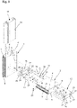
- FIG. 1 to 3 shows an embodiment of a T-connection between a mullion profile 1 and a transom profile 2, running transversely thereto, of a mullion-transom construction for facades, conservatories, skylights and the like. Shown in various representations.
- the two mullion and transom profiles 1 and 2 are designed as hollow profiles with a cavity 3 and an identical cross section. They each have two side walls 4 and 5 parallel to one another and two inner and outer end walls 6 and 7 which are perpendicular to the side walls 4 and 5 .
- the outer end wall 7 pointing to the outside of the mullion-transom construction contains an outwardly protruding web 8 with a receiving channel 9 open to the outside for fastening screws or other fastening elements, through the holding profiles (not shown here) or a holding structure for holding glass panes or others Facade elements on the outer end wall 7 can be attached.
- Right and left of the web 8 are on the outer End wall 7 also provided in the longitudinal direction of the post or transom profile 1 or 2 running receiving grooves 10 for receiving an inner seal or a sealing piece.
- the mullion profile 1 and the transom profile 2 are in the form of a metal profile tube produced, for example, by extrusion, which can be made of steel or aluminum. However, they can also be produced as a welded construction from a suitably bent and welded metal sheet, as a wooden or plastic construction or the like.
- the outwardly protruding web 8 on the outer end wall 7, which is directed to the outside and is used for fastening glass panes or other facade elements, has a receiving channel 9 designed as a screw channel in the exemplary embodiment shown. Fastening screws provided with a cutting thread, for example, can be screwed into the receiving channel 9 for fastening holding profiles or other supporting or facade elements.
- connection between the mullion profile 1 and the transom profile 2 is made via a connecting device, which has a plurality of pin-shaped connecting elements 11 that can be fastened to the side wall 5 of the mullion profile 1 in a predetermined arrangement or a predetermined pattern and a pin-shaped connecting element 11 that can be pushed in a form-fitting manner and inserted into the transom profile 2 insertable connection profile 12 contains.
- the pin-shaped connecting elements 11 are firmly connected via a connector with a plate-shaped first connector part 13 and a second connector part 14 designed as a connection profile to a holding profile 15 pushed into the post profile 1 .
- the holding profile 15 in figure 3 Threaded holes 16 shown and the post profile 1 with these aligned through holes 17 for a threaded pin 18 at the inner end of the pin-shaped connecting elements 11 on.
- the pin-shaped connecting elements 11 running at right angles to a longitudinal axis 19 of the vertical post profile 1 and parallel to a longitudinal axis 20 of the horizontal bar profile 2 are provided with cylindrical shaft parts 21 and a central annular collar 22 .
- the plate-shaped first connector part 13 has an outer contour adapted to the inner contour of the bar profile 2, so that the connector part 13 can be accommodated in the bar profile 2 with a positive fit and as far as possible without a gap. This enables the locking profile 2 to be held in a particularly stable manner.
- the first connector part 13 can be placed on the end face of the second connector part 14 and welded to it. However, the first connector part 13 can also be inserted into the second connector part 14 and firmly connected to it, for example by welding.
- the second connector part 14 designed as a profile can be reinforced by the plate-shaped first connector part 13 . In addition, the positioning and holding of the pin-shaped connecting elements 11 can be improved.
- the plate-shaped first connector part 13 also makes it possible for the pin-shaped connecting elements 11 to be clamped together.
- both the connecting profile 12 arranged in the transom profile 2 and the holding profile 15 used in the post profile 1 and also the second connector part 14 designed as a connection profile have the same cross section. They can therefore be produced simply and inexpensively from a single extruded profile, preferably designed as a roll-formed steel profile.
- the connecting profile 12 arranged in the locking profile 1 and also the second connector part 14 designed as a connecting profile have several insertion areas 25 and 26 adapted to the outer contour of the cylindrical shaft parts 21 of the pin-shaped connecting elements 11 and to their arrangement for inserting and positively accommodating the pin-shaped connecting elements 11 included.
- the connecting profile 12 and the connector part 14 have, on their inner end face facing the inner end wall 6 of the locking profile 2, an indentation 27 with three adjacent insertion areas 25 for receiving three triangularly arranged pin-shaped connecting elements 11.
- the connecting element 11 On its two side faces facing the side walls 4 and 5 of the locking profile 2, the connecting element 11 has a corrugated area 28 each with two lateral insertion areas 26 for inserting and receiving four further connecting elements 11 in a form-fitting manner. About the engagement of the pin-shaped connecting elements 11 in the insertion areas 25 and 26, a secure and precisely positioned connection between the mullion profile 1 and the transom profile 2 is achieved.
- the retaining profile 15 inserted into the post profile 1 also has the same cross section as the connecting profile 12 and the connector part 14 .
- the pin-shaped connecting elements 11 protrude through the through holes 17 in the post profile 1 and are screwed with their threaded pins 18 into the threaded holes 16 in the holding profile 15 .
- the pin-shaped connecting elements 11 protrude with their inner cylindrical shaft parts 21 through figure 3 shown bores 29 in the plate-shaped first connector part 13 and the insertion areas 25 and 26 of the second connector part 14. A secure mounting of the pin-shaped connecting elements 11 on the post profile 1 is thereby achieved.
- the connecting profile 12 together with the locking profile 2 can be slipped onto the outer cylindrical shaft parts 21 of the pin-shaped connecting elements 11 .
- the bolt profile 2 can then be secured via the screws 23 .
Landscapes
- Engineering & Computer Science (AREA)
- Architecture (AREA)
- Physics & Mathematics (AREA)
- Electromagnetism (AREA)
- Civil Engineering (AREA)
- Structural Engineering (AREA)
- Load-Bearing And Curtain Walls (AREA)
- Joining Of Building Structures In Genera (AREA)
Abstract
Description
- Die Erfindung betrifft eine T-Verbindung für Pfosten-Riegel-Konstruktionen, insbesondere von Fassaden, Lichtdächem und Wintergärten, nach dem Oberbegriff des Anspruchs 1. Die Erfindung betrifft außerdem eine Pfosten-Riegel-Konstruktion, bei der rechtwinklig zueinander angeordnete Pfosten- und Riegelprofile durch eine derartige T-Verbindung miteinander verbunden sind.
- Aus der
CN 104 674 991 A ist eine derartige T-Verbindung zwischen einem Pfosten- und Riegelprofil bekannt. Diese Verbindungseinrichtung enthält mehrere an einer Seitenwand eines Pfostenprofils in einer vorgegebenen Anordnung befestigbare stiftförmige Verbindungselemente und ein auf die stiftförmigen Verbindungselemente formschlüssig aufsteckbares und in ein Riegelprofil einschiebbares Verbindungsprofil. - Aufgabe der Erfindung ist es, eine T-Verbindung der eingangs genannten Art und eine Pfosten-Riegel-Konstruktion mit einer solchen T-Verbindung zu schaffen, die eine verbesserte lasttragende Verbindung von Pfosten- und Riegelprofilen ermöglichen.
- Diese Aufgabe wird durch eine T-Verbindung mit den Merkmalen des Anspruchs 1 und durch eine Pfosten-Riegel-Konstruktion mit den Merkmalen des Anspruchs 12 gelöst. Zweckmäßige Weiterbildungen und vorteilhafte Ausführungsformen der Erfindung sind Gegenstand der Unteransprüche.
- Bei der erfindungsgemäßen T-Verbindung enthält die zur formschlüssigen Verbindung eines Riegelprofils mit einem Pfostenprofil vorgesehene Verbindungseinrichtung mehrere an einer Seitenwand des Pfostenprofils in einer vorgegebenen Anordnung befestigbare stiftförmige Verbindungselemente und ein auf die stiftförmigen Verbindungselemente formschlüssig aufsteckbares und in das Riegelprofil einschiebbares Verbindungsprofil. Das Verbindungsprofil weist mehrere an die Außenkontur der stiftförmigen Verbindungselemente und an deren Anordnung angepasste Einschubbereiche zum Einschieben und zur formschlüssigen Aufnahme der stiftförmigen Verbindungselemente auf. Eine derartige T-Verbindung ist äußerst stabil und ermöglicht die Abtragung sehr hoher Glas- oder Füllungsgewichte, so dass z.B. auch ein Vordach an einer Fassadenkonstruktion befestigt werden kann. Durch die formschlüssige Verbindung des in das Riegelprofil einschiebbaren Verbindungsprofils mit den an Pfostenprofil befestigten Verbindungselementen kann das Riegelprofil ein hohes Torsionsmoment aufnehmen. Gleichzeitig kann durch das im Riegelprofil angeordnete Verbindungsprofil die Riegeldurchbiegung deutlich verringert und dadurch die Lastaufnahme verbessert werden.
- In einer vorteilhaften Ausgestaltung weist das Verbindungsprofil an einer inneren Stirnseite eine Einbuchtung mit drei nebeneinanderliegenden Einschubbereichen zur Aufnahme dreier dreiecksförmig angeordneter stiftförmiger Verbindungselemente auf. Das Verbindungsprofil kann außerdem an gegenüberliegenden Seitenflächen jeweils einen wellenförmigen Bereich mit jeweils zwei seitlichen Aufnahmebereichen zur Aufnahme von vier weiteren Verbindungselementen enthalten. Dadurch kann eine genaue und sichere Positionierung des Riegelprofils erreicht werden.
- Die stiftförmigen Verbindungselemente können zweckmäßigerweise über einen am Pfostenprofil angeordneten Verbinder fest mit dem Pfostenprofil verbunden sein. Der Verbinder kann aus einem z.B. plattenförmigen ersten Verbinderteil und einem mit diesem fest verbunden, z.B. als Anschlussprofil ausgebildeten zweiten Verbinderteil bestehen. Das als Anschlussprofil ausgebildete zweite Verbinderteil weist in vorteilhafter Weise denselben Querschnitt wie das Verbindungsprofil auf. Das erste Verbinderteil weist zweckmäßigerweise eine an die Innenkontur angepasste Außenkontur auf.
- In einer stabilen Bauweise können die stiftförmigen Verbindungselemente durch ein in das Pfostenprofil einsetzbares Halteprofil fest mit dem Pfostenprofil verbunden sein. Dabei können die stiftförmigen Verbindungselemente über einen Gewindezapfen in entsprechende Gewindebohrungen im Halteprofil eingeschraubt sein. Zweckmäßigerweise weist auch das Halteprofil denselben Querschnitt wie das Verbindungsprofil auf.
- Eine erfindungsgemäße Pfosten-Riegel-Konstruktion enthält miteinander verbundene Pfosten- und Riegelprofile, die durch die vorstehend erläuterte und im Folgenden noch näher beschriebene T-Verbindung miteinander verbunden sind.
- Weitere Besonderheiten und Vorzüge der Erfindung ergeben sich aus der folgenden Beschreibung eines bevorzugten Ausführungsbeispiels anhand der Zeichnung. Es zeigen:
- Figur 1
- ein Ausführungsbeispiel einer T-Verbindung zwischen einem Pfosten- und Riegelprofil im auseinandergebauten Zustand;
- Figur 2
- die T-Verbindung zwischen einem Pfosten- und Riegelprofil von
Figur 1 im zusammengebauten Zustand; - Figur 3
- die T-Verbindung von
Figur 1 in einer Explosionsansicht; - Figur 4
- einen Querschnitt durch das Riegelprofil und
- Figur 5
- einen Querschnitt durch das Pfostenprofil.
- In den
Figuren 1 bis 3 ist ein Ausführungsbeispiel einer T-Verbindung zwischen einem Pfostenprofil 1 und einem quer dazu verlaufenden Riegelprofil 2 einer Pfosten-Riegel-Konstruktion für Fassaden, Wintergärten, Lichtdächer und dgl. in verschiedenen Darstellungen gezeigt. Die beiden Pfosten- und Riegelprofile 1 und 2 sind in der gezeigten Ausführung als Hohlprofile mit einem Hohlraum 3 und identischem Querschnitt ausgeführt. Sie weisen jeweils zwei zueinander parallele Seitenwände 4 und 5 und zwei zu den Seitenwänden 4 und 5 rechtwinklige innere und äußere Stirnwände 6 und 7 auf. Die zur Außenseite der Pfosten-Riegel-Konstruktion weisende äußere Stirnwand 7 enthält einen nach außen vorstehenden Steg 8 mit einem und zur Außenseite hin offenen Aufnahmekanal 9 für Befestigungsschrauben oder andere Befestigungselemente, durch die hier nicht dargestellte Halteprofile oder eine Haltekonstruktion zur Halterung von Glasscheiben oder anderen Fassadenelementen an der äußeren Stirnwand 7 befestigt werden können. Rechts und links des Stegs 8 sind an der äußeren Stirnwand 7 außerdem in Längsrichtung des Pfosten- bzw. Riegelprofils 1 bzw. 2 verlaufende Aufnahmenuten 10 zur Aufnahme einer Innendichtung oder eines Dichtstücks vorgesehen. - Das Pfostenprofil 1 und das Riegelprofil 2 sind bei der gezeigten Ausführung in Form eines z.B. im Strangpressverfahren hergestellten Metallprofilrohrs ausgeführt, das aus Stahl oder Aluminium bestehen kann. Sie können aber auch als Schweißkonstruktion aus einem entsprechend gebogenen und verschweißten Metallblech, als Holz- bzw. Kunststoffkonstruktion oder dgl. hergestellt sein. Der nach außen vorstehende Steg 8 an der zur Außenseite gerichteten und zur Befestigung von Glasscheiben oder anderer Fassadenelemente dienenden äußeren Stirnwand 7 weist bei dem gezeigten Ausführungsbeispiel einen als Schraubkanal ausgeführten Aufnahmekanal 9 auf. In den Aufnahmekanal 9 können z.B. mit einem Schneidgewinde versehene Befestigungsschrauben zur Befestigung von Halteprofilen oder weiteren Trag- oder Fassadenelementen eingeschraubt werden.
- Die Verbindung zwischen dem Pfostenprofil 1 und dem Riegelprofil 2 erfolgt über eine Verbindungseinrichtung, die mehrere an der Seitenwand 5 des Pfostenprofils 1 in einer vorgegebenen Anordnung bzw. einem vorbestimmten Muster befestigbare stiftförmige Verbindungselemente 11 und ein auf die stiftförmigen Verbindungselemente 11 formschlüssig aufsteckbares und in das Riegelprofil 2 einschiebbares Verbindungsprofil 12 enthält. Die stiftförmigen Verbindungselemente 11 sind über einen Verbinder mit einem plattenförmigen ersten Verbinderteil 13 und einem als Anschlussprofil ausgebildeten zweiten Verbinderteil 14 fest mit einem in das Pfostenprofil 1 eingeschobenen Halteprofil 15 verbunden. Hierzu weist das Halteprofil 15 in
Figur 3 gezeigte Gewindebohrungen 16 und das Pfostenprofil 1 mit diesen fluchtende Durchgangsbohrungen 17 für einen Gewindezapfen 18 am inneren Ende der stiftförmigen Verbindungselemente 11 auf. Die rechtwinklig zu einer Längsachse 19 des vertikalen Pfostenprofils 1 und parallel zu einer Längsachse 20 des horizontalen Riegelprofils 2 verlaufenden stiftförmigen Verbindungselemente 11 sind mit zylindrischen Schaftteilen 21 und einem mittleren Ringbund 22 versehenen. Über Schrauben 23 und entsprechende Gewindebohrungen 24 in einer vorderen Seitenwand des zweiten Verbinderteils 14 kann das Riegelprofil 2 gegen Verschiebung gesichert an dem Pfostenprofil 1 gehalten werden. - Das plattenförmige erste Verbinderteil 13 weist eine an die Innenkontur des Riegelprofils 2 angepasste Außenkontur auf, so dass das Verbinderteil 13 formschlüssig und möglichst spaltfrei im Riegelprofil 2 aufgenommen werden kann. Dadurch ist eine besonders stabile Halterung des Riegelprofils 2 möglich. Das erste Verbinderteil 13 kann stirnseitig auf das zweite Verbinderteil 14 aufgesetzt und mit diesem verschweißt sein. Das erste Verbinderteil 13 kann aber auch in das zweite Verbinderteil 14 eingesetzt und z.B. durch Verschweißen fest mit diesem verbunden sein. Durch das plattenförmige erste Verbinderteil 13 kann das als Profil ausgebildete zweite Verbinderteil 14 ausgesteift werden. Außerdem kann die Positionierung und Halterung der stiftförmigen Verbindungselemente 11 verbessert werden. Das plattenförmige erste Verbinderteil 13 ermöglich es ferner, dass die stiftförmigen Verbindungselemente 11 miteinander verspannt werden.
- Wie aus den
Figuren 3 bis 5 hervorgeht, weisen sowohl das im Riegelprofil 2 angeordnete Verbindungsprofil 12 als auch das in das Pfostenprofil 1 eingesetzte Halteprofil 15 und auch das als Anschlussprofil ausgebildete zweite Verbinderteil 14 denselben Querschnitt auf. Sie können also einfach und kostengünstig aus einem einzigen, vorzugsweise als rollgeformtes Stahlprofil ausgeführten Strangprofil hergestellt werden. - In den
Figuren 3 und4 ist erkennbar, dass das im Riegelprofil 1 angeordnete Verbindungsprofil 12 und auch das als Anschlussprofil ausgebildete zweite Verbinderteil 14 mehrere an die Außenkontur der zylindrischen Schaftteile 21 der stiftförmigen Verbindungselemente 11 und an deren Anordnung angepasste Einschubbereiche 25 und 26 zum Einschieben und zur formschlüssigen Aufnahme der stiftförmigen Verbindungselemente 11 enthalten. In der gezeigten Ausführung weisen das Verbindungsprofil 12 und das Verbinderteil 14 an ihrer der inneren Stirnwand 6 des Riegelprofils 2 zugewandten inneren Stirnseite eine Einbuchtung 27 mit drei nebeneinanderliegenden Einschubbereichen 25 für die Aufnahme dreier dreiecksförmig angeordneter stiftförmiger Verbindungselemente 11 auf. An seinen beiden den Seitenwänden 4 und 5 des Riegelprofils 2 zugewandten Seitenflächen weist das Verbindungselement 11 jeweils einen wellenförmigen Bereich 28 mit jeweils zwei seitlichen Einschubbereichen 26 zum Einschieben und zur formschlüssigen Aufnahme von vier weiteren Verbindungselementen 11 auf. Über den Eingriff der stiftförmigen Verbindungselemente 11 in die Einschubbereiche 25 und 26 wird eine sichere und positionsgenaue Verbindung zwischen dem Pfostenprofil 1 und dem Riegelprofil 2 erreicht. - Aus
Figur 5 ist ersichtlich, dass auch das in das Pfostenprofil 1 eingeschobene Halteprofil 15 denselben Querschnitt wie das Verbindungsprofil 12 und das Verbinderteil 14 aufweist. Die stiftförmigen Verbindungselemente 11 ragen durch die Durchgangsbohrungen 17 im Pfostenprofil 1 und sind mit ihren Gewindezapfen 18 in die Gewindebohrungen 16 im Halteprofil 15 eingeschraubt. Mit ihren inneren zylindrischen Schaftteilen 21 ragen die stiftförmigen Verbindungselemente 11 durch inFigur 3 gezeigte Bohrungen 29 in dem plattenförmigen ersten Verbinderteil 13 und die Einschubbereiche 25 und 26 des zweiten Verbinderteils 14. Dadurch wird eine sichere Halterung der stiftförmigen Verbindungselemente 11 am Pfostenprofil 1 erreicht. Auf die äußeren zylindrischen Schaftteile 21 der stiftförmigen Verbindungselemente 11 ist das Verbindungsprofil 12 zusammen mit dem Riegelprofil 2 aufsteckbar. Über die Schrauben 23 kann dann das Riegelprofil 2 gesichert werden. -
- 1
- Pfostenprofil
- 2
- Riegelprofil
- 3
- Hohlraum
- 4
- Seitenwand
- 5
- Seitenwand
- 6
- Innere Stirnwand
- 7
- Äußere Stirnwand
- 8
- Steg
- 9
- Aufnahmekanal
- 10
- Aufnahmenut
- 11
- Stiftförmiges Verbindungselement
- 12
- Verbindungsprofil
- 13
- Erstes Verbinderteil
- 14
- Zweites Verbinderteil
- 15
- Halteprofil
- 16
- Gewindebohrung
- 17
- Durchgangsbohrung
- 18
- Gewindezapfen
- 19
- Längsachse des Pfostenprofils
- 20
- Längsachse des Riegelprofils
- 21
- Schaftteil
- 22
- Ringbund
- 23
- Schraube
- 24
- Gewindebohrung
- 25
- Einschubbereich
- 26
- Einschubbereich
- 27
- Einbuchtung
- 28
- Wellenförmiger Bereich
- 29
- Bohrung
Claims (12)
- T-Verbindung für Pfosten-Riegel-Konstruktionen von Fassaden, Lichtdächern und Wintergärten, die eine Verbindungseinrichtung zur formschlüssigen Verbindung eines Riegelprofils (2) mit einem Pfostenprofil (1) enthält, wobei die Verbindungeinrichtung mehrere an einer Seitenwand (5) des Pfostenprofils (1) in einer vorgegebenen Anordnung befestigbare stiftförmige Verbindungselemente (11) und ein auf die stiftförmigen Verbindungselemente (11) formschlüssig aufsteckbares und in das Riegelprofil (2) einschiebbares Verbindungsprofil (12) enthält, dadurch gekennzeichnet, dass das Verbindungsprofil (12) mehrere an die Außenkontur der stiftförmigen Verbindungselemente (11) und an deren Anordnung angepasste Einschubbereiche (25, 26) zum Einschieben und zur formschlüssigen Aufnahme der stiftförmigen Verbindungselemente (11) enthält.
- T-Verbindung nach Anspruch 1, dadurch gekennzeichnet, dass das Verbindungsprofil (12) an einer inneren Stirnseite eine Einbuchtung (27) mit drei nebeneinanderliegenden Einschubbereichen (25) zur Aufnahme dreier dreiecksförmig angeordneter stiftförmiger Verbindungselemente (11) enthält.
- T-Verbindung nach Anspruch 1 oder 2, dadurch gekennzeichnet, dass das Verbindungsprofil (12) an gegenüberliegenden Seitenflächen jeweils einen wellenförmigen Bereich (28) mit jeweils zwei seitlichen Einschubbereichen (26) zur Aufnahme von vier Verbindungselementen (11) aufweist.
- T-Verbindung nach einem der Ansprüche 1 bis 3, dadurch gekennzeichnet, dass die stiftförmigen Verbindungselemente (11) zylindrische Schaftteile (21) zur Anordnung in den Einschubbereichen (25, 26) des Verbindungsprofils (12) aufweisen.
- T-Verbindung nach Anspruch 1 bis 4, dadurch gekennzeichnet, dass die stiftförmigen Verbindungselemente (11) über einen am Pfostenprofil (1) angeordneten Verbinder (13, 14) fest mit dem Pfostenprofil (1) verbunden sind.
- T-Verbindung nach Anspruch 5, dadurch gekennzeichnet, dass der Verbinder (13, 14) aus einem ersten Verbinderteil (13) und einem mit diesem fest verbundenen zweiten Verbinderteil (14) besteht.
- T-Verbindung nach Anspruch 6, dadurch gekennzeichnet, dass das zweite Verbinderteil (14) als Anschlussprofil mit demselben Querschnitt wie das Verbindungsprofil (12) ausgebildet ist.
- T-Verbindung nach Anspruch 6 oder 7, dadurch gekennzeichnet, dass das erste Verbinderteil (13) eine an die Innenkontur des Riegelprofils (2) angepasste Außenkontur aufweist.
- T-Verbindung nach einem der Ansprüche 1 bis 8, dadurch gekennzeichnet, dass die stiftförmigen Verbindungselemente (11) durch ein in das Pfostenprofil (1) einsetzbares Halteprofil (15) fest mit dem Pfostenprofil (1) verbunden sind.
- T-Verbindung nach Anspruch 9, dadurch gekennzeichnet, dass die stiftförmigen Verbindungselemente (11) über einen Gewindezapfen (18) in entsprechende Gewindebohrungen (16) im Halteprofil (15) eingeschraubt sind.
- T-Verbindung nach Anspruch 9 oder 10, dadurch gekennzeichnet, dass das Halteprofil (15) denselben Querschnitt wie das Verbindungsprofil (12) aufweist.
- Pfosten/Riegel-Konstruktion, insbesondere für Fassaden und Wintergärten, die miteinander verbundene Pfostenprofile (1) und Riegelprofile (2) enthält, dadurch gekennzeichnet, dass die Pfostenprofile (1) und die Riegelprofile (2) durch eine T-Verbindung nach einem der Ansprüche 1 bis 11 miteinander verbunden sind.
Applications Claiming Priority (1)
| Application Number | Priority Date | Filing Date | Title |
|---|---|---|---|
| DE102020132662.9A DE102020132662A1 (de) | 2020-12-08 | 2020-12-08 | T-Verbindung für Pfosten-Riegel-Konstruktionen und Pfosten- Riegel-Konstruktion mit einer derartigen T-Verbindung |
Publications (2)
| Publication Number | Publication Date |
|---|---|
| EP4012132A1 true EP4012132A1 (de) | 2022-06-15 |
| EP4012132B1 EP4012132B1 (de) | 2024-03-06 |
Family
ID=78592566
Family Applications (1)
| Application Number | Title | Priority Date | Filing Date |
|---|---|---|---|
| EP21207047.8A Active EP4012132B1 (de) | 2020-12-08 | 2021-11-09 | T-verbindung für pfosten-riegel-konstruktionen und pfosten-riegel-konstruktion mit einer derartigen t-verbindung |
Country Status (2)
| Country | Link |
|---|---|
| EP (1) | EP4012132B1 (de) |
| DE (1) | DE102020132662A1 (de) |
Cited By (1)
| Publication number | Priority date | Publication date | Assignee | Title |
|---|---|---|---|---|
| CN118997372A (zh) * | 2024-10-10 | 2024-11-22 | 吉祥佳利铝业江苏有限公司 | 一种幕墙铝单板多级连接构造 |
Citations (4)
| Publication number | Priority date | Publication date | Assignee | Title |
|---|---|---|---|---|
| GB2176217A (en) * | 1985-03-30 | 1986-12-17 | James Alan Macey | Interconnecting mullions and transoms of curtain walls |
| US5042216A (en) * | 1988-12-22 | 1991-08-27 | Mannesmann Ag | Locking element for a wall facade structure |
| EP0814215A1 (de) * | 1996-06-21 | 1997-12-29 | Staba Wuppermann GmbH | Fassadensystem, sowie Befestigungssystem |
| CN104674991A (zh) | 2015-02-11 | 2015-06-03 | 北京西飞世纪门窗幕墙工程有限责任公司 | 框架幕墙横竖框销钉连接系统及其连接方法 |
Family Cites Families (2)
| Publication number | Priority date | Publication date | Assignee | Title |
|---|---|---|---|---|
| DE19953557C1 (de) | 1999-11-03 | 2001-07-12 | Rp Technik Gmbh | Verkleidungssystem für Fassaden und Dächer von Bauwerken |
| DE202008014975U1 (de) | 2008-11-12 | 2010-04-01 | Raico Bautechnik Gmbh | T-Verbindung zwischen einem Pfosten- und Riegelprofil |
-
2020
- 2020-12-08 DE DE102020132662.9A patent/DE102020132662A1/de not_active Withdrawn
-
2021
- 2021-11-09 EP EP21207047.8A patent/EP4012132B1/de active Active
Patent Citations (4)
| Publication number | Priority date | Publication date | Assignee | Title |
|---|---|---|---|---|
| GB2176217A (en) * | 1985-03-30 | 1986-12-17 | James Alan Macey | Interconnecting mullions and transoms of curtain walls |
| US5042216A (en) * | 1988-12-22 | 1991-08-27 | Mannesmann Ag | Locking element for a wall facade structure |
| EP0814215A1 (de) * | 1996-06-21 | 1997-12-29 | Staba Wuppermann GmbH | Fassadensystem, sowie Befestigungssystem |
| CN104674991A (zh) | 2015-02-11 | 2015-06-03 | 北京西飞世纪门窗幕墙工程有限责任公司 | 框架幕墙横竖框销钉连接系统及其连接方法 |
Cited By (1)
| Publication number | Priority date | Publication date | Assignee | Title |
|---|---|---|---|---|
| CN118997372A (zh) * | 2024-10-10 | 2024-11-22 | 吉祥佳利铝业江苏有限公司 | 一种幕墙铝单板多级连接构造 |
Also Published As
| Publication number | Publication date |
|---|---|
| DE102020132662A1 (de) | 2022-06-09 |
| EP4012132B1 (de) | 2024-03-06 |
Similar Documents
| Publication | Publication Date | Title |
|---|---|---|
| DE1927040C3 (de) | Vorrichtung zum stirnseitigen Anschluß eines Strangprofils an einem zumindest an der Verbindungsstelle durchlaufenden Strangprofil insbessondere aus Leicht metall, Kunststoff od dgl | |
| EP3529430B1 (de) | Pfosten für eine pfosten-riegel-konstruktion | |
| DE3419294A1 (de) | T-verbinder fuer einen sprossenstoss in einer vorsatzfassade | |
| DE102005044980B4 (de) | Stoßverbinder für Holz-/Aluminiumfassaden | |
| EP0976891B1 (de) | Aufbausystem | |
| EP3130717A1 (de) | Pfosten-riegel-verbindung | |
| EP0004374A1 (de) | Vorrichtung zum Verbinden von zwei Profilstäben | |
| EP4012132B1 (de) | T-verbindung für pfosten-riegel-konstruktionen und pfosten-riegel-konstruktion mit einer derartigen t-verbindung | |
| EP1729018B2 (de) | Profilverbindungssystem | |
| DE3603221C2 (de) | ||
| DE102004016212B4 (de) | Eckverbindung für einen Fenster-, Tür- oder Fassadenrahmen | |
| EP2186959B1 (de) | T-Verbindung zwischen einem Pfosten- und Riegelprofil | |
| EP1635075B1 (de) | Verbindungsvorrichtung | |
| DE10349791B4 (de) | Pfosten-Riegel-Verbindung zwischen einem Pfosten und wenigstens einem an einer Pfostenseite stirnseitig anschließenden Riegel aus Holz oder Holzwerkstoff | |
| DE102020106891B4 (de) | T-Verbindung zwischen einem Pfosten- und Riegelprofil und Pfosten-Riegel-Konstruktion mit einer derartigen T-Verbindung | |
| EP2042748A1 (de) | Gratleiste für Massivholz | |
| EP4386216B1 (de) | Blechverbindung | |
| DE10229272A1 (de) | Stoßverbinder zum winkeligen Verbinden von Hohlprofilen | |
| DE102020111612B4 (de) | Verbinderanordnung zum winkligen verbinden von jeweils ein anschlussprofil und ein aufschiebprofil umfassenden hohlprofilen sowie einer profilanordnung mit einer solchen verbinderanordnung | |
| EP3327215B1 (de) | Pfosten-riegel-fassade | |
| DD296135A5 (de) | Verbindungstraeger zur befestigung von rahmenkonstruktionen | |
| DE202024104432U1 (de) | Baugruppe mit wenigstens einem Konstruktionsprofil | |
| EP1744066B1 (de) | Fachwerk sowie Stäbe für ein Fachwerk | |
| DE9105384U1 (de) | Gestell aus Profilstangen, die mittels Verbindungselementen zusammengesetzt sind | |
| DE29905533U1 (de) | Schraube zur gegenseitigen Verbindung von stumpf oder in einem Gehrungsschnitt aneinander anliegenden oder aneinander anstoßenden Holzprofilen |
Legal Events
| Date | Code | Title | Description |
|---|---|---|---|
| PUAI | Public reference made under article 153(3) epc to a published international application that has entered the european phase |
Free format text: ORIGINAL CODE: 0009012 |
|
| STAA | Information on the status of an ep patent application or granted ep patent |
Free format text: STATUS: THE APPLICATION HAS BEEN PUBLISHED |
|
| AK | Designated contracting states |
Kind code of ref document: A1 Designated state(s): AL AT BE BG CH CY CZ DE DK EE ES FI FR GB GR HR HU IE IS IT LI LT LU LV MC MK MT NL NO PL PT RO RS SE SI SK SM TR |
|
| STAA | Information on the status of an ep patent application or granted ep patent |
Free format text: STATUS: REQUEST FOR EXAMINATION WAS MADE |
|
| 17P | Request for examination filed |
Effective date: 20221215 |
|
| RBV | Designated contracting states (corrected) |
Designated state(s): AL AT BE BG CH CY CZ DE DK EE ES FI FR GB GR HR HU IE IS IT LI LT LU LV MC MK MT NL NO PL PT RO RS SE SI SK SM TR |
|
| GRAP | Despatch of communication of intention to grant a patent |
Free format text: ORIGINAL CODE: EPIDOSNIGR1 |
|
| STAA | Information on the status of an ep patent application or granted ep patent |
Free format text: STATUS: GRANT OF PATENT IS INTENDED |
|
| RIC1 | Information provided on ipc code assigned before grant |
Ipc: E04B 1/58 20060101ALN20231130BHEP Ipc: F16B 7/04 20060101ALI20231130BHEP Ipc: F16B 7/18 20060101ALI20231130BHEP Ipc: E04D 3/08 20060101ALI20231130BHEP Ipc: E06B 3/968 20060101ALI20231130BHEP Ipc: E04B 2/96 20060101AFI20231130BHEP |
|
| INTG | Intention to grant announced |
Effective date: 20231213 |
|
| GRAS | Grant fee paid |
Free format text: ORIGINAL CODE: EPIDOSNIGR3 |
|
| GRAA | (expected) grant |
Free format text: ORIGINAL CODE: 0009210 |
|
| STAA | Information on the status of an ep patent application or granted ep patent |
Free format text: STATUS: THE PATENT HAS BEEN GRANTED |
|
| AK | Designated contracting states |
Kind code of ref document: B1 Designated state(s): AL AT BE BG CH CY CZ DE DK EE ES FI FR GB GR HR HU IE IS IT LI LT LU LV MC MK MT NL NO PL PT RO RS SE SI SK SM TR |
|
| REG | Reference to a national code |
Ref country code: CH Ref legal event code: EP |
|
| P01 | Opt-out of the competence of the unified patent court (upc) registered |
Effective date: 20240214 |
|
| REG | Reference to a national code |
Ref country code: IE Ref legal event code: FG4D Free format text: LANGUAGE OF EP DOCUMENT: GERMAN |
|
| REG | Reference to a national code |
Ref country code: DE Ref legal event code: R096 Ref document number: 502021002891 Country of ref document: DE |
|
| REG | Reference to a national code |
Ref country code: LT Ref legal event code: MG9D |
|
| PG25 | Lapsed in a contracting state [announced via postgrant information from national office to epo] |
Ref country code: LT Free format text: LAPSE BECAUSE OF FAILURE TO SUBMIT A TRANSLATION OF THE DESCRIPTION OR TO PAY THE FEE WITHIN THE PRESCRIBED TIME-LIMIT Effective date: 20240306 |
|
| REG | Reference to a national code |
Ref country code: NL Ref legal event code: MP Effective date: 20240306 |
|
| PG25 | Lapsed in a contracting state [announced via postgrant information from national office to epo] |
Ref country code: GR Free format text: LAPSE BECAUSE OF FAILURE TO SUBMIT A TRANSLATION OF THE DESCRIPTION OR TO PAY THE FEE WITHIN THE PRESCRIBED TIME-LIMIT Effective date: 20240607 |
|
| PG25 | Lapsed in a contracting state [announced via postgrant information from national office to epo] |
Ref country code: HR Free format text: LAPSE BECAUSE OF FAILURE TO SUBMIT A TRANSLATION OF THE DESCRIPTION OR TO PAY THE FEE WITHIN THE PRESCRIBED TIME-LIMIT Effective date: 20240306 Ref country code: RS Free format text: LAPSE BECAUSE OF FAILURE TO SUBMIT A TRANSLATION OF THE DESCRIPTION OR TO PAY THE FEE WITHIN THE PRESCRIBED TIME-LIMIT Effective date: 20240606 |
|
| PG25 | Lapsed in a contracting state [announced via postgrant information from national office to epo] |
Ref country code: ES Free format text: LAPSE BECAUSE OF FAILURE TO SUBMIT A TRANSLATION OF THE DESCRIPTION OR TO PAY THE FEE WITHIN THE PRESCRIBED TIME-LIMIT Effective date: 20240306 |
|
| PG25 | Lapsed in a contracting state [announced via postgrant information from national office to epo] |
Ref country code: RS Free format text: LAPSE BECAUSE OF FAILURE TO SUBMIT A TRANSLATION OF THE DESCRIPTION OR TO PAY THE FEE WITHIN THE PRESCRIBED TIME-LIMIT Effective date: 20240606 Ref country code: NO Free format text: LAPSE BECAUSE OF FAILURE TO SUBMIT A TRANSLATION OF THE DESCRIPTION OR TO PAY THE FEE WITHIN THE PRESCRIBED TIME-LIMIT Effective date: 20240606 Ref country code: LT Free format text: LAPSE BECAUSE OF FAILURE TO SUBMIT A TRANSLATION OF THE DESCRIPTION OR TO PAY THE FEE WITHIN THE PRESCRIBED TIME-LIMIT Effective date: 20240306 Ref country code: HR Free format text: LAPSE BECAUSE OF FAILURE TO SUBMIT A TRANSLATION OF THE DESCRIPTION OR TO PAY THE FEE WITHIN THE PRESCRIBED TIME-LIMIT Effective date: 20240306 Ref country code: GR Free format text: LAPSE BECAUSE OF FAILURE TO SUBMIT A TRANSLATION OF THE DESCRIPTION OR TO PAY THE FEE WITHIN THE PRESCRIBED TIME-LIMIT Effective date: 20240607 Ref country code: FI Free format text: LAPSE BECAUSE OF FAILURE TO SUBMIT A TRANSLATION OF THE DESCRIPTION OR TO PAY THE FEE WITHIN THE PRESCRIBED TIME-LIMIT Effective date: 20240306 Ref country code: ES Free format text: LAPSE BECAUSE OF FAILURE TO SUBMIT A TRANSLATION OF THE DESCRIPTION OR TO PAY THE FEE WITHIN THE PRESCRIBED TIME-LIMIT Effective date: 20240306 Ref country code: BG Free format text: LAPSE BECAUSE OF FAILURE TO SUBMIT A TRANSLATION OF THE DESCRIPTION OR TO PAY THE FEE WITHIN THE PRESCRIBED TIME-LIMIT Effective date: 20240306 |
|
| PG25 | Lapsed in a contracting state [announced via postgrant information from national office to epo] |
Ref country code: SE Free format text: LAPSE BECAUSE OF FAILURE TO SUBMIT A TRANSLATION OF THE DESCRIPTION OR TO PAY THE FEE WITHIN THE PRESCRIBED TIME-LIMIT Effective date: 20240306 Ref country code: LV Free format text: LAPSE BECAUSE OF FAILURE TO SUBMIT A TRANSLATION OF THE DESCRIPTION OR TO PAY THE FEE WITHIN THE PRESCRIBED TIME-LIMIT Effective date: 20240306 |
|
| PG25 | Lapsed in a contracting state [announced via postgrant information from national office to epo] |
Ref country code: NL Free format text: LAPSE BECAUSE OF FAILURE TO SUBMIT A TRANSLATION OF THE DESCRIPTION OR TO PAY THE FEE WITHIN THE PRESCRIBED TIME-LIMIT Effective date: 20240306 |
|
| PG25 | Lapsed in a contracting state [announced via postgrant information from national office to epo] |
Ref country code: NL Free format text: LAPSE BECAUSE OF FAILURE TO SUBMIT A TRANSLATION OF THE DESCRIPTION OR TO PAY THE FEE WITHIN THE PRESCRIBED TIME-LIMIT Effective date: 20240306 |
|
| PG25 | Lapsed in a contracting state [announced via postgrant information from national office to epo] |
Ref country code: IS Free format text: LAPSE BECAUSE OF FAILURE TO SUBMIT A TRANSLATION OF THE DESCRIPTION OR TO PAY THE FEE WITHIN THE PRESCRIBED TIME-LIMIT Effective date: 20240706 |
|
| PG25 | Lapsed in a contracting state [announced via postgrant information from national office to epo] |
Ref country code: SM Free format text: LAPSE BECAUSE OF FAILURE TO SUBMIT A TRANSLATION OF THE DESCRIPTION OR TO PAY THE FEE WITHIN THE PRESCRIBED TIME-LIMIT Effective date: 20240306 Ref country code: PT Free format text: LAPSE BECAUSE OF FAILURE TO SUBMIT A TRANSLATION OF THE DESCRIPTION OR TO PAY THE FEE WITHIN THE PRESCRIBED TIME-LIMIT Effective date: 20240708 |
|
| PG25 | Lapsed in a contracting state [announced via postgrant information from national office to epo] |
Ref country code: CZ Free format text: LAPSE BECAUSE OF FAILURE TO SUBMIT A TRANSLATION OF THE DESCRIPTION OR TO PAY THE FEE WITHIN THE PRESCRIBED TIME-LIMIT Effective date: 20240306 Ref country code: EE Free format text: LAPSE BECAUSE OF FAILURE TO SUBMIT A TRANSLATION OF THE DESCRIPTION OR TO PAY THE FEE WITHIN THE PRESCRIBED TIME-LIMIT Effective date: 20240306 |
|
| PG25 | Lapsed in a contracting state [announced via postgrant information from national office to epo] |
Ref country code: PL Free format text: LAPSE BECAUSE OF FAILURE TO SUBMIT A TRANSLATION OF THE DESCRIPTION OR TO PAY THE FEE WITHIN THE PRESCRIBED TIME-LIMIT Effective date: 20240306 |
|
| PG25 | Lapsed in a contracting state [announced via postgrant information from national office to epo] |
Ref country code: SK Free format text: LAPSE BECAUSE OF FAILURE TO SUBMIT A TRANSLATION OF THE DESCRIPTION OR TO PAY THE FEE WITHIN THE PRESCRIBED TIME-LIMIT Effective date: 20240306 |
|
| PG25 | Lapsed in a contracting state [announced via postgrant information from national office to epo] |
Ref country code: SM Free format text: LAPSE BECAUSE OF FAILURE TO SUBMIT A TRANSLATION OF THE DESCRIPTION OR TO PAY THE FEE WITHIN THE PRESCRIBED TIME-LIMIT Effective date: 20240306 Ref country code: SK Free format text: LAPSE BECAUSE OF FAILURE TO SUBMIT A TRANSLATION OF THE DESCRIPTION OR TO PAY THE FEE WITHIN THE PRESCRIBED TIME-LIMIT Effective date: 20240306 Ref country code: RO Free format text: LAPSE BECAUSE OF FAILURE TO SUBMIT A TRANSLATION OF THE DESCRIPTION OR TO PAY THE FEE WITHIN THE PRESCRIBED TIME-LIMIT Effective date: 20240306 Ref country code: PT Free format text: LAPSE BECAUSE OF FAILURE TO SUBMIT A TRANSLATION OF THE DESCRIPTION OR TO PAY THE FEE WITHIN THE PRESCRIBED TIME-LIMIT Effective date: 20240708 Ref country code: PL Free format text: LAPSE BECAUSE OF FAILURE TO SUBMIT A TRANSLATION OF THE DESCRIPTION OR TO PAY THE FEE WITHIN THE PRESCRIBED TIME-LIMIT Effective date: 20240306 Ref country code: IS Free format text: LAPSE BECAUSE OF FAILURE TO SUBMIT A TRANSLATION OF THE DESCRIPTION OR TO PAY THE FEE WITHIN THE PRESCRIBED TIME-LIMIT Effective date: 20240706 Ref country code: EE Free format text: LAPSE BECAUSE OF FAILURE TO SUBMIT A TRANSLATION OF THE DESCRIPTION OR TO PAY THE FEE WITHIN THE PRESCRIBED TIME-LIMIT Effective date: 20240306 Ref country code: CZ Free format text: LAPSE BECAUSE OF FAILURE TO SUBMIT A TRANSLATION OF THE DESCRIPTION OR TO PAY THE FEE WITHIN THE PRESCRIBED TIME-LIMIT Effective date: 20240306 |
|
| PG25 | Lapsed in a contracting state [announced via postgrant information from national office to epo] |
Ref country code: IT Free format text: LAPSE BECAUSE OF FAILURE TO SUBMIT A TRANSLATION OF THE DESCRIPTION OR TO PAY THE FEE WITHIN THE PRESCRIBED TIME-LIMIT Effective date: 20240306 |
|
| REG | Reference to a national code |
Ref country code: DE Ref legal event code: R097 Ref document number: 502021002891 Country of ref document: DE |
|
| PG25 | Lapsed in a contracting state [announced via postgrant information from national office to epo] |
Ref country code: IT Free format text: LAPSE BECAUSE OF FAILURE TO SUBMIT A TRANSLATION OF THE DESCRIPTION OR TO PAY THE FEE WITHIN THE PRESCRIBED TIME-LIMIT Effective date: 20240306 |
|
| PLBE | No opposition filed within time limit |
Free format text: ORIGINAL CODE: 0009261 |
|
| STAA | Information on the status of an ep patent application or granted ep patent |
Free format text: STATUS: NO OPPOSITION FILED WITHIN TIME LIMIT |
|
| PG25 | Lapsed in a contracting state [announced via postgrant information from national office to epo] |
Ref country code: DK Free format text: LAPSE BECAUSE OF FAILURE TO SUBMIT A TRANSLATION OF THE DESCRIPTION OR TO PAY THE FEE WITHIN THE PRESCRIBED TIME-LIMIT Effective date: 20240306 |
|
| PG25 | Lapsed in a contracting state [announced via postgrant information from national office to epo] |
Ref country code: DK Free format text: LAPSE BECAUSE OF FAILURE TO SUBMIT A TRANSLATION OF THE DESCRIPTION OR TO PAY THE FEE WITHIN THE PRESCRIBED TIME-LIMIT Effective date: 20240306 |
|
| 26N | No opposition filed |
Effective date: 20241209 |
|
| PG25 | Lapsed in a contracting state [announced via postgrant information from national office to epo] |
Ref country code: SI Free format text: LAPSE BECAUSE OF FAILURE TO SUBMIT A TRANSLATION OF THE DESCRIPTION OR TO PAY THE FEE WITHIN THE PRESCRIBED TIME-LIMIT Effective date: 20240306 |
|
| PG25 | Lapsed in a contracting state [announced via postgrant information from national office to epo] |
Ref country code: MC Free format text: LAPSE BECAUSE OF FAILURE TO SUBMIT A TRANSLATION OF THE DESCRIPTION OR TO PAY THE FEE WITHIN THE PRESCRIBED TIME-LIMIT Effective date: 20240306 |
|
| PG25 | Lapsed in a contracting state [announced via postgrant information from national office to epo] |
Ref country code: LU Free format text: LAPSE BECAUSE OF NON-PAYMENT OF DUE FEES Effective date: 20241109 |
|
| REG | Reference to a national code |
Ref country code: BE Ref legal event code: MM Effective date: 20241130 |
|
| PG25 | Lapsed in a contracting state [announced via postgrant information from national office to epo] |
Ref country code: BE Free format text: LAPSE BECAUSE OF NON-PAYMENT OF DUE FEES Effective date: 20241130 |
|
| PG25 | Lapsed in a contracting state [announced via postgrant information from national office to epo] |
Ref country code: IE Free format text: LAPSE BECAUSE OF NON-PAYMENT OF DUE FEES Effective date: 20241109 |
|
| REG | Reference to a national code |
Ref country code: CH Ref legal event code: U11 Free format text: ST27 STATUS EVENT CODE: U-0-0-U10-U11 (AS PROVIDED BY THE NATIONAL OFFICE) Effective date: 20251201 |
|
| PGFP | Annual fee paid to national office [announced via postgrant information from national office to epo] |
Ref country code: DE Payment date: 20251211 Year of fee payment: 5 |
|
| PGFP | Annual fee paid to national office [announced via postgrant information from national office to epo] |
Ref country code: AT Payment date: 20260113 Year of fee payment: 5 |
|
| PGFP | Annual fee paid to national office [announced via postgrant information from national office to epo] |
Ref country code: FR Payment date: 20251120 Year of fee payment: 5 |
|
| PGFP | Annual fee paid to national office [announced via postgrant information from national office to epo] |
Ref country code: CH Payment date: 20251201 Year of fee payment: 5 |
|
| PG25 | Lapsed in a contracting state [announced via postgrant information from national office to epo] |
Ref country code: HU Free format text: LAPSE BECAUSE OF FAILURE TO SUBMIT A TRANSLATION OF THE DESCRIPTION OR TO PAY THE FEE WITHIN THE PRESCRIBED TIME-LIMIT; INVALID AB INITIO Effective date: 20211109 |
|
| PG25 | Lapsed in a contracting state [announced via postgrant information from national office to epo] |
Ref country code: CY Free format text: LAPSE BECAUSE OF FAILURE TO SUBMIT A TRANSLATION OF THE DESCRIPTION OR TO PAY THE FEE WITHIN THE PRESCRIBED TIME-LIMIT; INVALID AB INITIO Effective date: 20211109 |