EP4012134B1 - Befestigungselement zum befestigen von sichtprofilen und terrassensystem hiermit - Google Patents
Befestigungselement zum befestigen von sichtprofilen und terrassensystem hiermit Download PDFInfo
- Publication number
- EP4012134B1 EP4012134B1 EP20213244.5A EP20213244A EP4012134B1 EP 4012134 B1 EP4012134 B1 EP 4012134B1 EP 20213244 A EP20213244 A EP 20213244A EP 4012134 B1 EP4012134 B1 EP 4012134B1
- Authority
- EP
- European Patent Office
- Prior art keywords
- fastening element
- base plate
- spacer
- fastening
- spring
- Prior art date
- Legal status (The legal status is an assumption and is not a legal conclusion. Google has not performed a legal analysis and makes no representation as to the accuracy of the status listed.)
- Active
Links
Images

Classifications
-
- E—FIXED CONSTRUCTIONS
- E04—BUILDING
- E04F—FINISHING WORK ON BUILDINGS, e.g. STAIRS, FLOORS
- E04F15/00—Flooring
- E04F15/02—Flooring or floor layers composed of a number of similar elements
- E04F15/02044—Separate elements for fastening to an underlayer
-
- E—FIXED CONSTRUCTIONS
- E04—BUILDING
- E04F—FINISHING WORK ON BUILDINGS, e.g. STAIRS, FLOORS
- E04F13/00—Coverings or linings, e.g. for walls or ceilings
- E04F13/07—Coverings or linings, e.g. for walls or ceilings composed of covering or lining elements; Sub-structures therefor; Fastening means therefor
- E04F13/08—Coverings or linings, e.g. for walls or ceilings composed of covering or lining elements; Sub-structures therefor; Fastening means therefor composed of a plurality of similar covering or lining elements
- E04F13/0801—Separate fastening elements
- E04F13/0803—Separate fastening elements with load-supporting elongated furring elements between wall and covering elements
- E04F13/081—Separate fastening elements with load-supporting elongated furring elements between wall and covering elements with additional fastening elements between furring elements and covering elements
- E04F13/0821—Separate fastening elements with load-supporting elongated furring elements between wall and covering elements with additional fastening elements between furring elements and covering elements the additional fastening elements located in-between two adjacent covering elements
- E04F13/0826—Separate fastening elements with load-supporting elongated furring elements between wall and covering elements with additional fastening elements between furring elements and covering elements the additional fastening elements located in-between two adjacent covering elements engaging side grooves running along the whole length of the covering elements
-
- E—FIXED CONSTRUCTIONS
- E04—BUILDING
- E04F—FINISHING WORK ON BUILDINGS, e.g. STAIRS, FLOORS
- E04F15/00—Flooring
- E04F15/02—Flooring or floor layers composed of a number of similar elements
- E04F15/02044—Separate elements for fastening to an underlayer
- E04F2015/0205—Separate elements for fastening to an underlayer with load-supporting elongated furring elements between the flooring elements and the underlayer
- E04F2015/02066—Separate elements for fastening to an underlayer with load-supporting elongated furring elements between the flooring elements and the underlayer with additional fastening elements between furring elements and flooring elements
- E04F2015/02077—Separate elements for fastening to an underlayer with load-supporting elongated furring elements between the flooring elements and the underlayer with additional fastening elements between furring elements and flooring elements the additional fastening elements located in-between two adjacent flooring elements
- E04F2015/02094—Engaging side grooves running along the whole length of the flooring elements
-
- E—FIXED CONSTRUCTIONS
- E04—BUILDING
- E04F—FINISHING WORK ON BUILDINGS, e.g. STAIRS, FLOORS
- E04F2201/00—Joining sheets or plates or panels
- E04F2201/05—Separate connectors or inserts, e.g. pegs, pins, keys or strips
- E04F2201/0523—Separate tongues; Interlocking keys, e.g. joining mouldings of circular, square or rectangular shape
- E04F2201/0547—Separate tongues; Interlocking keys, e.g. joining mouldings of circular, square or rectangular shape adapted to be moved perpendicular to the joint edge
Definitions
- the invention relates to a terrace system and a fastening element for fastening a first and second visible profile, in particular a terrace profile, to a substructure, the fastening element having two opposing broad sides, long sides and end faces, with a base plate which is designed to engage in mutually opposing grooves on mutually facing profile long sides of the first and second viewing profile is formed, with a first and a second spring element, which protrude from the base plate on the first broad side of the fastening element and are designed to rest resiliently on the groove of the second viewing profile, the first and second spring elements extending from the base plate to their respective free ends, extending parallel to one another in the direction of the second longitudinal side, with a spacer extending from and projecting from the base plate for spacing the first and second visible profiles from one another and with a first mounting opening for a fastening means.
- the EP3453814A1 a fastening element which, on the one hand, uses two spacers to determine the minimum distance between two end faces of adjacent visible profiles and, on the other hand, uses its base plate to hold the visible profiles to a substructure by engaging this base plate in the grooves on the long profile sides of the two visible profiles.
- the fastening element itself is attached to the substructure using a self-tapping screw as a fastening means, for which the screw passes through a central mounting opening on the base plate.
- the fastening element When tightening the fastening element, if the tightening torque is impermissibly high, the fastening element may twist, which can undesirably change the position of the visible profiles relative to one another - in particular reinforced by the spacers on the two long sides of the fastening element. Such a change in position of the visible profiles cannot be prevented by the two spring elements of the fastening element, which protrude from the base plate on the first broad side of the fastening element and are designed to rest resiliently on a groove of a visible profile.
- JP2008031757A aims to provide a floor surface device which is intended to make it possible to connect the floor surface of a building terrace or balcony by arranging narrow and long decking materials parallel to each other without screwing screws directly from the top surface.
- the invention has therefore set itself the task of changing the construction of a fastening element of the type described in order to facilitate the assembly of visible profiles.
- the invention solves the problem set by the features of claim 1.
- the spacer By disposing the spacer between the first and second spring elements and having the first mounting opening, the risk of undesirable twisting of the fastening element when it is tightened onto a substructure can be significantly reduced. This is not only because the distance between the mounting opening and the spacer provided in the prior art is eliminated - but also because a fastening means can be positioned firmly between the first and second viewing profile by arranging the spacer between the first and second spring elements.
- the mounting opening is also easier to reach because it extends further into the open gap between the two viewing profiles and is easier to see and see.
- the spacer can serve as a guide for a fastener to facilitate secure assembly.
- the fastening means according to the invention is therefore suitable for ensuring a particularly simple, stable and positionally stable assembly, whereby excessive tightening torques are prevented and their undesirable effects are reduced.
- Assembly is further facilitated by the first and second spring elements and the spacer of the base plate being arranged on the first broad side of the fastening element.
- first and second spring elements and the spacer of the base plate being arranged on the first broad side of the fastening element.
- the first and second spring elements extend from the first longitudinal side of the fastening element in the direction of the second longitudinal side of the fastening element.
- Such spring elements which are designed to be comparatively long in this way, can, for example, improve the clamping of the fastening element in a groove of the second visible profile and thus further facilitate its assembly.
- the production of such spring elements on a fastening element is also comparatively simple.
- the first spring element is arranged on the first end face of the fastening element and the second spring element on the second end face of the fastening element, the dimensions of the fastening element can be reduced and construction and production can be further simplified.
- first and second spring elements each have a first longitudinal section which runs away from the base plate and a second longitudinal section which runs towards the second broad side of the fastening element. In this way, the spring element can be clamped in the groove of a longitudinal side of the profile.
- the second longitudinal section has the respective free end of the spring element, in order to facilitate the insertion of the fastening element into a groove of the second visible profile.
- the handling of the fastening element during assembly can be further improved if the spacer is arranged centrally on the base plate.
- the first mounting opening is arranged centrally on the spacer, which distributes the load caused by the tightening torque of the fastener evenly across the spacer and avoids incorrect loading. This can further facilitate the assembly of the fastening element.
- the height of the spacer can protrude beyond the first and second spring elements. This can be particularly advantageous when assembling the fastening element if the spring elements have not yet been inserted into the relevant groove of the second visible profile and are in a spring-loaded position.
- the spacer can have a trapezoidal outer contour in cross section, which can contribute to increasing the mechanical stability and that of the fastening element and can also ensure a stable distribution of the tightening force of a fastening element.
- the attachment of the fastening element to the substructure can be further improved if a second mounting opening is provided in the base plate between the spacer and the first spring element and a third mounting opening is provided between the spacer and the second spring element.
- the first mounting opening penetrates the spacer and the base plate in order to further facilitate the attachment of the fastening element to the substructure.
- the construction and assembly of the fastening element can be made easier if the base plate is flat on the second broad side of the fastening element.
- the fastening element is formed in one piece, its production can be simplified and the costs for this can be reduced - especially if it is made from a plastic material, preferably by an injection molding process.
- the base plate can have a recess along the spring elements in order to increase the mobility of the spring elements.
- the fastening element according to the invention is used in a terrace system with a first and a second visible profile and with a substructure in order to hold the two visible profiles on the substructure or thus fasten them to the substructure.
- the base plate of the fastening element engages in grooves in the first and second visible profiles.
- the spring elements rest resiliently in the groove of the second visible profile.
- the longitudinal profile sides of the first and second viewing profiles preferably lie against the spacer.
- the first broad side of the fastening element faces away from the substructure.
- FIG. 1 Terrace system 100 shown has several, namely two, visible profiles 1, 2 and a fastening element 3, which attaches the first and second visible profiles 1, 2 to a substructure 4, for example to a floor, clamps and thus fastens.
- the two visible profiles 1, 2 are preferably terrace profiles and/or have a solid wood profile and/or are designed as planks.
- the fastening element 3 with two opposing broad sides 3a, 3b, two opposing long sides 3c, 3d and two opposing end faces 3e, 3f, has a base plate 5, two resilient spring elements 6, 7, a spacer 8 and a mounting opening 9 .
- the base plate 5 is longer and wider than the spacer 8, and is designed to engage in the opposing grooves 1a, 1b of the longitudinal profile sides 1b, 2b of the two visible profiles 1, 2 facing each other. This is done - as in Fig. 1 to recognize - by the base plate 5 protruding into both grooves 1a, 1b of the first viewing profile 1 and the second viewing profile 2.
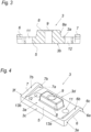
- the first and second spring elements 6, 7 protrude from the base plate 5 on the first broad side 3a of the fastening element 3, as in Fig. 4 to recognize.
- the first broad side 3a can be viewed as the top of the fastening element 3 and the second broad side 3b can be viewed as the underside of the fastening element 3.
- Both spring elements 6, 7 rest on the groove 2a of the second visible profile 2 and thus fix the fastening element 3 in its position.
- the first spring element 6 and the second spring element 7 run parallel.
- the two spring elements 6, 7 each extend from the base plate 5 on the first broad side 3a to their respective free ends 6a, 7a in the direction of the second long side 3d.
- the two spring elements 6, 7 preferably run normal to the first and/or second longitudinal side 3c, 3d.
- the spacer 8 extends from the base plate 5 and protrudes from the base plate 5 and uses its width as a stop to determine the minimum distance between the two viewing profiles 1, 2.
- a first mounting opening 9 on the fastening element 3 is used to fasten the fastening element 3 to the substructure 4 by a fastening means 10, namely a wood screw, passing through this mounting opening 9.
- the fastening means 10 presses down the fastening element 3, which in turn holds down the first and second visible profiles 1, 2 via the base plate 5 engaging in their grooves 1a, 2a and thus fastens them to the substructure 4.
- the spacer 8 is now arranged between the first and second spring elements 6, 7 and also has the first mounting opening 9.
- this assembly opening is 9 - as in Fig. 1 can be seen - also arranged higher than the base plate 5, which leads to easier accessibility during assembly.
- the arrangement of the first mounting opening 9 on the spacer 8 and between the spring elements 6, 7 is particularly characterized in that the fastening element 3 does not twist even with a high tightening torque on the fastening means 10. The distance set between the two viewing profiles 1, 2 is therefore always maintained, which makes installation considerably easier.
- first and second spring elements 6, 7 extend from the first long side 3c of the fastening element 3 in the direction of their free ends 6a, 7a to the second long side 3d of the fastening element 3.
- these two spring elements 6, 7 are each on one end face 3e and 3f of the fastening element 3 are provided, which leads to particularly compact external dimensions on the fastening element 3.
- the base plate 5 preferably has a recess 13a, 13b along the spring elements 6, 7. This can, for example, increase the mobility of the spring elements 6, 7.
- the first and second spring elements 6, 7 each have two longitudinal sections 6b, 6c and 7b, 7c, respectively.
- the first longitudinal section 6b or 7b starts from the base plate 5 and runs away from the base plate 5, as shown in FIG Fig. 4 can be recognized.
- the second longitudinal section 6c or 7c runs towards the base plate 5 or the second broad side 3b of the fastening element 3 and has the respective free end 6a or 7a of the spring element 6, 7. This means that the spring elements 6, 7 can be inserted into the groove 2a of the second viewing profile 2 in a way that is easy to handle.
- the spacer 8 protrudes in height from the first and second spring elements 6, 7, whereby the spacer 8 can always have exposed stop surfaces. This is despite the arrangement of the spring elements 6, 7 on the same broad side 3a of the fastening element 3.
- the spacer 8 has a trapezoidal outer contour 8a in longitudinal section in order to be able to distribute the tightening forces of the fastening means 10 on the base plate 5 in a stable manner.
- a second and a third mounting opening 11, 12 are also provided on the fastening element 3 - namely on the base plate 5. These mounting openings 11, 12 are between the spacer 8 and the first and second spring element 6, 7 arranged and improve the assembly conditions of the fastening element 3.
- the first mounting opening 9 penetrates the spacer 8 and the base plate 5 - whereby the mounting means 10 can easily be provided on the fastening element 3.
- the base plate 5 is flat on the second broad side 3b of the fastening element 3 in order to facilitate the positioning of the fastening element 3 in the respective groove 1a, 2a of the two visible profiles 1, 2.
- the fastening element 3 which is made of a plastic material, is also designed in one piece and can therefore be produced inexpensively.
- the fastening element 3 holds the two visible profiles 1, 2 on the substructure 4.
- the base plate 5 of the fastening element 3 projects into both grooves 1a, 2a of the two visible profiles 1, 2.
- the first and second spring elements 6, 7 rest resiliently on the groove 2a of the second viewing profile 2.
- the first broad side 3b of the fastening element 3 faces away from the substructure 4.
- the second broad side 3b of the fastening element 3 lies opposite the substructure 4.
Landscapes
- Engineering & Computer Science (AREA)
- Architecture (AREA)
- Civil Engineering (AREA)
- Structural Engineering (AREA)
- Connection Of Plates (AREA)
- Clamps And Clips (AREA)
Description
- Die Erfindung betrifft ein Terrassensystem und ein Befestigungselement zum Befestigen eines ersten und zweiten Sichtprofils, insbesondere Terrassenprofils, an einer Unterkonstruktion, wobei das Befestigungselement zwei einander gegenüberliegende Breitseiten, Längsseiten und Stirnseiten aufweist, mit einer Grundplatte, die zum Eingreifen in einander gegenüberliegende Nuten einander zugewandter Profillängsseiten des ersten und zweiten Sichtprofils ausgebildet ist, mit einem ersten und einem zweiten Federelement, die der Grundplatte an der ersten Breitseite des Befestigungselements vorstehen und zum federnden Anliegen an der Nut des zweiten Sichtprofils ausgebildet sind, wobei sich das erste und zweite Federelement ausgehend von der Grundplatte zu ihrem jeweiligen freien Ende parallel zueinander verlaufend in Richtung der zweiten Längsseite erstrecken, mit einem von der Grundplatte ausgehenden und dieser vorstehenden Abstandshalter zum Beabstanden des ersten und zweiten Sichtprofils voneinander und mit einer ersten Montageöffnung für ein Befestigungsmittel.
- Um Sicht- bzw. Terrassenprofile voneinander zu beabstanden und zu befestigen, ist aus der
EP3453814A1 ein Befestigungselement bekannt, das einerseits mit zwei Abstandshaltern den Mindestabstand zwischen zwei Stirnseiten aneinander angrenzender Sichtprofile festlegt und andererseits mithilfe seiner Grundplatte die Sichtprofile an einer Unterkonstruktion festhält, indem diese Grundplatte in die Nuten an den Profillängsseiten der beiden Sichtprofile eingreift. Das Befestigungselement selbst wird über eine selbstschneidende Schraube als Befestigungsmittel an der Unterkonstruktion befestigt, wobei hierfür die Schraube eine mittige Montageöffnung an der Grundplatte durchgreift. - Beim Anziehen des Befestigungselements kann es bei unzulässig hohen Anzugsmomenten unter Umständen zu einem Verdrehen des Befestigungselements kommen, was die Lage der Sichtprofile zueinander unerwünscht verändern kann - insbesondere verstärkt durch die Abstandshalter an den beiden Längsseiten des Befestigungselements. Eine derartige Lageveränderung der Sichtprofile können auch die beiden Federelemente des Befestigungselements nicht verhindern, welche der Grundplatte an der ersten Breitseite des Befestigungselements vorstehen und zum federnden Anliegen an einer Nut eines Sichtprofils ausgebildet sind.
- Zudem kann, je nach vorliegenden Bedingungen und Dimensionen der zu montierenden Teile, bei eingesetztem Befestigungselement, dessen Montageöffnung vergleichsweise tief zwischen den beiden Sichtprofilen liegen, was die Montage des Befestigungselements erschweren und die Gefahr, nicht korrekte Anzugskräfte auf das Befestigungsmittel vorzusehen, erhöhen kann.
- Ein Stand der Technik gemäß dem Oberbegriff des Anspruchs 1 ist in der
JP2008031757A - Die Erfindung hat sich daher die Aufgabe gestellt, ein Befestigungselement der eingangs geschilderten Art in der Konstruktion zu verändern, um die Montage von Sichtprofilen zu erleichtern.
- Die Erfindung löst die gestellte Aufgabe durch die Merkmale des Anspruchs 1. Indem der Abstandshalter zwischen dem ersten und zweiten Federelement angeordnet ist und die erste Montageöffnung aufweist, kann die Gefahr eines unerwünschten Verdrehens des Befestigungselements bei dessen Anziehen an eine Unterkonstruktion deutlich verringert werden. Dies nicht nur deshalb, weil der im Stand der Technik gegebene Abstand zwischen Montageöffnung und Abstandshalter beseitigt wird - sondern auch, weil ein Befestigungsmittel durch die Anordnung des Abstandshalters zwischen erstem und zweitem Federelement standfest zwischen erstem und zweitem Sichtprofil positionierbar ist. Auch ist die Montageöffnung leichter erreichbar, da diese weiter in den offenen Spalt zwischen den beiden Sichtprofilen erstreckt und besser erkennbar sowie einsehbar ist. Des Weiteren kann der Abstandhalter als Führung für ein Befestigungselement dienen, um eine sichere Montage zu erleichtern. Das erfindungsgemäße Befestigungsmittel ist demnach geeignet, eine besonders einfache, standfeste und lagestabile Montage sicherzustellen, wobei zu hohe Anzugsmomente verhindert und in ihren unerwünschten Auswirkungen reduziert werden.
- Die Montage wird weiter erleichtert, indem das erste und zweite Federelement sowie der Abstandshalter der Grundplatte an der ersten Breitseite des Befestigungselements angeordnet sind. Derart kann eine besonders einfache und sichere Ausrichtung des Befestigungselements erfolgen - auch ist es möglich, etwa bei Wartungsarbeiten, die wesentlichen Merkmale für die Funktion des Befestigungselements besonders leicht zu prüfen.
- Erfindungsgemäß erstrecken sich das erste und zweite Federelement von der ersten Längsseite des Befestigungselements ausgehend in Richtung der zweiten Längsseite des Befestigungselements. Solche, auf diese Weise vergleichsweise lang ausgeführte Federelemente können beispielsweise das Festklemmen des Befestigungselements in einer Nut des zweiten Sichtprofils verbessern und damit dessen Montage weiter erleichtern. Auch ist die Herstellung solcher Federelemente an einem Befestigungselement vergleichsweise einfach.
- Sind das erste Federelement an der ersten Stirnseite des Befestigungselements und das zweite Federelement an der zweiten Stirnseite des Befestigungselements angeordnet, können die Abmessungen des Befestigungselements reduzieren und Konstruktion sowie Herstellung weiter vereinfacht werden.
- Eine besonders effektive und sicher Montage ist erreichbar, wenn das erste und zweite Federelement jeweils einen ersten Längsabschnitt aufweisen, der von der Grundplatte weg gerichtet verläuft, und einen zweiten Längsabschnitt aufweisen, der der zweiten Breitseite des Befestigungselements zu gerichtet verläuft. Auf diese Weise kann etwa eine Klemmung des Federelements in der Nut einer Profillängsseite erfolgen.
- Vorzugsweise weist der zweite Längsabschnitt das jeweilige freie Ende des Federelements auf, um etwa das Einführen des Befestigungselements in eine Nut des zweiten Sichtprofils zu erleichtern.
- Die Handhabung des Befestigungselements bei der Montage ist weiter verbesserbar, wenn der Abstandshalter an der Grundplatte mittig angeordnet ist.
- Vorzugsweise ist die erste Montageöffnung am Abstandshalter mittig angeordnet, was die Belastung durch das Anzugsmoment des Befestigungsmittels gleichmäßig auf den Abstandshalter aufteilt und Fehlbelastungen vermeidet. Damit kann die Montage des Befestigungselements weiter erleichtert werden.
- Der Abstandshalter kann in seiner Höhe dem ersten und zweiten Federelement überstehen. Dies kann insbesondere bei der Montage des Befestigungselements von Vorteil sein, wenn die Federelemente noch nicht in die betreffende Nut des zweiten Sichtprofils eingeführt sind und sich diese in einer aufgefederten Lage befinden.
- Der Abstandshalter kann im Querschnitt eine trapezförmige Außenkontur aufweisen, was einen Beitrag zur Erhöhung der mechanischen Stabilität sowie jener des Befestigungselements liefern und auch eine standfeste Verteilung der Anzugskraft eines Befestigungselements sicherstellen kann.
- Die Befestigung des Befestigungselements an der Unterkonstruktion ist weiter verbesserbar, wenn in der Grundplatte zwischen Abstandshalter und erstem Federelement eine zweite Montageöffnung sowie zwischen Abstandshalter und zweitem Federelement eine dritte Montageöffnung vorgesehen sind.
- Vorzugsweise durchdringt die erste Montageöffnung den Abstandshalter und die Grundplatte, um die Befestigung des Befestigungselements an der Unterkonstruktion weiter zu erleichtern.
- Die Konstruktion und Montage des Befestigungselements kann erleichtert werden, wenn die Grundplatte an der zweiten Breitseite des Befestigungselements plan ist.
- Wenn das Befestigungselement einstückig ausgebildet ist, ist dessen Herstellung zu vereinfachen und sind die Kosten hierfür zu verringern - insbesondere, wenn es aus einem Kunststoffwerkstoff hergestellt werden, vorzugsweise durch ein Spritzgießverfahren.
- Die Grundplatte kann entlang der Federelemente je einen Rücksprung aufweisen, um damit die Beweglichkeit der Federelemente zu erhöhen.
- Insbesondere von Vorteil ist, wenn das erfindungsgemäße Befestigungselement bei einem Terrassensystem mit einem ersten und einem zweiten Sichtprofil und mit einer Unterkonstruktion verwendet wird, um die beiden Sichtprofile an der Unterkonstruktion zu halten bzw. damit an der Unterkonstruktion zu befestigen.
- Vorzugsweise greift hierbei die Grundplatte des Befestigungselements in Nuten des ersten und zweiten Sichtprofils ein. Vorzugsweise liegen die Federelemente in die Nut des zweiten Sichtprofils federnd an. Vorzugsweise liegen die Profillängsseiten des ersten und zweiten Sichtprofils an den Abstandshalter an. Vorzugsweise ist die erste Breitseite des Befestigungselements von der Unterkonstruktion abgewandt.
- In den Figuren ist beispielsweise der Erfindungsgegenstand anhand einer Ausführungsvariante dargestellt. Es zeigen
- Fig. 1
- eine Schnittansicht quer durch ein Terrassensystem mit einem Befestigungselement
- Fig. 2
- eine Draufsicht auf das Befestigungselement nach
Fig. 1 und - Fig. 3
- eine Schnittansicht nach III-III der
Fig. 2 und - Fig. 4
- eine dreidimensionale Ansicht auf das Befestigungselement nach den
Figuren 1 bis 3 . - Das beispielsweise nach
Fig. 1 dargestellte Terrassensystem 100 weist mehrere, nämlich zwei, Sichtprofile 1, 2 und ein Befestigungselement 3 auf, welches das erste und zweite Sichtprofil 1, 2 an eine Unterkonstruktion 4, beispielsweise an einen Boden, klemmt und damit befestigt. Die beiden Sichtprofile 1, 2 sind vorzugsweise Terrassenprofile und/oder weisen ein Vollholzprofil auf und/oder sind als Dielen ausgebildet. - Das Befestigungselement 3, mit zwei einander gegenüberliegende Breitseiten 3a, 3b, zwei einander gegenüberliegende Längsseiten 3c, 3d und zwei einander gegenüberliegende Stirnseiten 3e, 3f, weist eine Grundplatte 5, zwei federnd ausgebildete Federelemente 6, 7, einen Abstandshalter 8 und eine Montageöffnung 9 auf.
- Die Grundplatte 5 ist länger und breiter als der Abstandshalter 8, und zum Eingreifen in die einander gegenüberliegende Nuten 1a, 1b einander zugewandter Profillängsseiten 1b, 2b der beiden Sichtprofile 1, 2 ausgebildet. Dies erfolgt - wie in
Fig. 1 zu erkennen -, indem die Grundplatte 5 in beide Nuten 1a, 1b des ersten Sichtprofils 1 und des zweiten Sichtprofils 2 einragt. - Das erste und das zweite Federelement 6, 7 stehen der Grundplatte 5 an ersten Breitseite 3a des Befestigungselements 3 vor, wie in
Fig. 4 zu erkennen. In der Darstellung und Ausrichtung des Ausführungsbeispiels nachFigur 1 und4 kann die erste Breitseite 3a als Oberseite des Befestigungselements 3 und die zweite Breitseite 3b als Unterseite des Befestigungselements 3 angesehen werden. - Beide Federelement 6, 7 liegen an der Nut 2a des zweiten Sichtprofils 2 an, und fixieren damit das Befestigungselement 3 in ihrer Lage. Das erste Federelement 6 und das zweite Federelement 7 verlaufen parallel. Hierzu erstrecken sich die beiden Federelement 6, 7 jeweils von der Grundplatte 5 an der ersten Breitseite 3a ausgehend bis zu ihren jeweiligen freien Ende 6a, 7a in Richtung der zweiten Längsseite 3d. Vorzugsweise verlaufen die beiden Federelement 6, 7 normal zur ersten und/oder zweite Längsseite 3c, 3d.
- Der Abstandshalter 8 geht von der Grundplatte 5 aus und steht der Grundplatte 5 vor und legt mit seiner Breite als Anschlag den Mindestabstand zwischen den beiden Sichtprofilen 1, 2 fest.
- Eine erste Montageöffnung 9 am Befestigungselement 3 dient zur Befestigung des Befestigungselements 3 an der Unterkonstruktion 4, indem diese Montageöffnung 9 von einem Befestigungsmittel 10, nämlich einer Holzschraube, durchgriffen wird. Das Befestigungsmittel 10 drückt das Befestigungselement 3 nieder, was wiederum das erste und zweite Sichtprofil 1, 2 über die in deren Nuten 1a, 2a eingreifende Grundplatte 5 niederhält und somit an der Unterkonstruktion 4 befestigt.
- Erfindungsgemäß ist nun der Abstandshalter 8 zwischen dem ersten und zweiten Federelement 6, 7 angeordnet und weist auch die erste Montageöffnung 9 auf. Damit ist diese Montageöffnung 9 - wie in
Fig. 1 zu erkennen - auch gegenüber der Grundplatte 5 erhöht angeordnet, was bei der Montage zu einer leichteren Zugänglichkeit führt. Besonders aber zeichnet sich die Anordnung der ersten Montageöffnung 9 am Abstandshalter 8 und zwischen den Federelement 6, 7 dahin gehend aus, dass sich das Befestigungselements 3 selbst bei einem hohen Anzugsmoment auf das Befestigungsmittel 10 nicht verdreht. Der zwischen den beiden Sichtprofile 1, 2 eingestellte Abstand bleibt daher stets erhalten, was die Montage erheblich erleichtert. Dies zudem weiter, indem das erste und zweite Federelement 6, 7 sowie der Abstandshalter 8 der Grundplatte 5 an der ersten Breitseite 3a des Befestigungselements 3 angeordnet sind. - Wie der
Fig. 2 zu entnehmen, erstrecken sich das erste und zweite Federelement 6, 7 von der ersten Längsseite 3c des Befestigungselements 3 ausgehend in Richtung ihrer freien Ende 6a, 7a zur zweiten Längsseite 3d des Befestigungselements 3. Außerdem sind diese beiden Federelemente 6, 7 jeweils an einer Stirnseite 3e bzw. 3f des Befestigungselements 3 vorgesehen, was besonders zu kompakten Außenabmessung am Befestigungselement 3 führt. - Vorzugsweise weist die Grundplatte 5 entlang der Federelemente 6, 7 je einen Rücksprung 13a, 13b auf. Dies kann beispielsweise die Beweglichkeit der Federelemente 6, 7 erhöhen.
- Das erste und zweite Federelement 6, 7 weisen je zwei Längsabschnitte 6b, 6c bzw. 7b, 7c auf. Der erste Längsabschnitt 6b bzw. 7b geht von der Grundplatte 5 aus und läuft von der Grundplatte 5 weg, wie dies in der
Fig. 4 erkannt werden kann. - Der zweite Längsabschnitt 6c bzw. 7c läuft der Grundplatte 5 bzw. der zweiten Breitseite 3b des Befestigungselements 3 zu und weist das jeweilige freie Ende 6a bzw. 7a des Federelements 6, 7 auf. Damit können die Federelement 6, 7 handhabungsfreundlich in die Nut 2a des zweiten Sichtprofils 2 eingeführt werden.
- Symmetrische Verhältnisse in den Abmessungen für eine gleichmäßige Kraftverteilung ergeben sich, wenn der Abstandshalter 8 an der Grundplatte 5 mittig angeordnet ist und die erste Montageöffnung 9 am Abstandshalter 8 mittig angeordnet ist.
- Wie in
Fig. 3 zu erkennen, steht der Abstandshalter 8 der Höhe nach dem ersten und zweiten Federelement 6, 7 über, wodurch der Abstandshalter 8 stets freigestellte Anschlagflächen aufweisen kann. Dies trotz der Anordnung der Federelemente 6, 7 an der gleichen Breitseite 3a des Befestigungselements 3. Zudem weist der Abstandshalter 8 im Längsschnitt eine trapezförmige Außenkontur 8a auf, um die Anzugskräfte des Befestigungsmittels 10 auf die Grundplatte 5 standfest verteilen zu können. - Neben der ersten Montageöffnung 9 am Abstandshalter 8 sind am Befestigungselement 3 noch eine zweite und eine dritte Montageöffnung 11, 12 vorgesehen - und zwar an der Grundplatte 5. Diese Montageöffnungen 11, 12 sind zwischen dem Abstandshalter 8 und dem ersten bzw. zweiten Federelement 6, 7 angeordnet und verbessern die Montagebedingungen des Befestigungselements 3.
- Wie der
Fig. 3 zu entnehmen, durchdringt die erste Montageöffnung 9 den Abstandshalter 8 und die Grundplatte 5 - wodurch das Montagemittel 10 einfach am Befestigungselement 3 vorgesehen werden kann. - Zudem ist die Grundplatte 5 an der zweiten Breitseite 3b des Befestigungselements 3 plan, um die Positionierung des Befestigungselements 3 in der jeweiligen Nut 1a, 2a der beiden Sichtprofile 1, 2 zu erleichtern.
- Das aus einem Kunststoffwerkstoff bestehende Befestigungselement 3 ist zudem einstückig ausgebildet und damit kostengünstig herstellbar.
- Wie in
Fig. 1 zum Terrassensystem 100 weiter zu erkennen, hält das Befestigungselement 3 die beiden Sichtprofile 1, 2 an der Unterkonstruktion 4. Die Grundplatte 5 des Befestigungselements 3 ragt in beide Nuten 1a, 2a der beiden Sichtprofile 1, 2 ein. Das erste und zweite Federelement 6, 7 liegen federnd an der Nut 2a des zweiten Sichtprofils 2 an. Die erste Breitseite 3b des Befestigungselements 3 ist von der Unterkonstruktion 4 abgewandt. Die zweite Breitseite 3b des Befestigungselements 3 liegt der Unterkonstruktion 4 gegenüber.
Claims (15)
- Befestigungselement zum Befestigen eines ersten und zweiten Sichtprofils (1, 2), insbesondere Terrassenprofils, an einer Unterkonstruktion (4), wobei das Befestigungselement (3) zwei einander gegenüberliegende Breitseiten (3a, 3b), Längsseiten (3c, 3d) und Stirnseiten (3e, 3f) aufweist,mit einer Grundplatte (5), die zum Eingreifen in einander gegenüberliegende Nuten (1a, 2a) einander zugewandter Profillängsseiten (1b, 2b) des ersten und zweiten Sichtprofils (1, 2) ausgebildet ist,mit einem ersten und einem zweiten Federelement (6, 7), die der Grundplatte (5) an der ersten Breitseite (3a) des Befestigungselements (3) vorstehen und zum federnden Anliegen an der Nut (2a) des zweiten Sichtprofils (2) ausgebildet sind,wobei sich das erste und zweite Federelement (6, 7) ausgehend von der Grundplatte (5) zu ihrem jeweiligen freien Ende (6a, 7a) parallel zueinander verlaufend in Richtung der zweiten Längsseite (3d) erstrecken,mit einem von der Grundplatte (5) ausgehenden und dieser vorstehenden Abstandshalter (8) zum Beabstanden des ersten und zweiten Sichtprofils (1, 2) voneinanderund mit einer ersten Montageöffnung (9) für ein Befestigungsmittel (10),wobei der Abstandshalter (8) zwischen dem ersten und zweiten Federelement (6, 7) angeordnet ist und die erste Montageöffnung (9) aufweist und wobeidas erste und zweite Federelement (6, 7) sowie der Abstandshalter (8) der Grundplatte (5) an der ersten Breitseite (3a) des Befestigungselements (3) angeordnet sind,dadurch gekennzeichnet, dass sich das erste und zweite Federelement (6, 7) von der ersten Längsseite (3c) ausgehend in Richtung ihrer freien Enden (6a, 7a) zur zweiten Längsseite (3d) erstrecken.
- Befestigungselement nach Anspruch 1, dadurch gekennzeichnet, dass das erste Federelement (6) an der ersten Stirnseite (3e) des Befestigungselements (3) und das zweite Federelement (7) an der zweiten Stirnseite (3f) des Befestigungselements (3) angeordnet sind.
- Befestigungselement nach Anspruch 1 oder 2, dadurch gekennzeichnet, dass das erste und zweite Federelement (6, 7) jeweils einen ersten Längsabschnitt (6b, 7b), der von der Grundplatte (5) weg gerichtet verläuft, und einen zweiten Längsabschnitt (6c, 7c) aufweisen, der der zweiten Breitseite (3b) des Befestigungselements (3) zu gerichtet verläuft.
- Befestigungselement nach Anspruch 3, dadurch gekennzeichnet, dass der zweite Längsabschnitt (6c, 7c) das jeweilige freie Ende (6a, 7a) des Federelements (6, 7) aufweist.
- Befestigungselement nach einem der Ansprüche 1 bis 4, dadurch gekennzeichnet, dass der Abstandshalter (8) an der Grundplatte (5) mittig angeordnet ist.
- Befestigungselement nach einem der Ansprüche 1 bis 5, dadurch gekennzeichnet, dass die erste Montageöffnung (9) am Abstandshalter (8) mittig angeordnet ist.
- Befestigungselement nach einem der Ansprüche 1 bis 6, dadurch gekennzeichnet, dass der Abstandshalter (8) in seiner Höhe dem ersten und zweiten Federelement (6, 7) übersteht.
- Befestigungselement nach einem der Ansprüche 1 bis 7, dadurch gekennzeichnet, dass der Abstandshalter (8) im Querschnitt eine trapezförmige Außenkontur (8a) aufweist.
- Befestigungselement nach einem der Ansprüche 1 bis 8, dadurch gekennzeichnet, dass in der Grundplatte (5) zwischen Abstandshalter (8) und erstem Federelement (6) eine zweite Montageöffnung (11) sowie zwischen Abstandshalter (8) und zweitem Federelement (6) eine dritte Montageöffnung (12) vorgesehen sind.
- Befestigungselement nach einem der Ansprüche 1 bis 9, dadurch gekennzeichnet, dass die erste Montageöffnung (9) den Abstandshalter (8) und die Grundplatte (5) durchdringt.
- Befestigungselement nach einem der Ansprüche 1 bis 10, dadurch gekennzeichnet, dass die Grundplatte (5) an der zweiten Breitseite (3b) des Befestigungselements (3) plan ist.
- Befestigungselement nach einem der Ansprüche 1 bis 11, dadurch gekennzeichnet, dass das Befestigungselement (3) einstückig ausgebildet ist, insbesondere aus einem Kunststoffwerkstoff besteht.
- Befestigungselement nach einem der Ansprüche 1 bis 12, dadurch gekennzeichnet, dass die Grundplatte (5) entlang der Federelemente (6, 7) je einen Rücksprung (13a, 13b) aufweist.
- Terrassensystem mit einem ersten und zweiten Sichtprofil (1, 2), mit einer Unterkonstruktion (4) und mit einem Befestigungselement (3) nach einem der Ansprüche 1 bis 13 zum Befestigen des ersten und zweiten Sichtprofils (1, 2) an der Unterkonstruktion (4).
- Terrassensystem nach Anspruch 14, dadurch gekennzeichnet, dass die Grundplatte (5) des Befestigungselements (3) in Nuten (1a, 2a) des ersten und zweiten Sichtprofils (1, 2) eingreift und/oder dass die Federelemente (6, 7) in die Nut (2a) des zweiten Sichtprofils (2) federnd anliegen und/oder dass die Profillängsseiten (1b, 2b) des ersten und zweiten Sichtprofils (1, 2) an dem Abstandshalter (8) anliegen und/oder dass die erste Breitseite (3a) des Befestigungselements (3) von der Unterkonstruktion (4) abgewandt ist.
Priority Applications (1)
| Application Number | Priority Date | Filing Date | Title |
|---|---|---|---|
| EP20213244.5A EP4012134B1 (de) | 2020-12-10 | 2020-12-10 | Befestigungselement zum befestigen von sichtprofilen und terrassensystem hiermit |
Applications Claiming Priority (1)
| Application Number | Priority Date | Filing Date | Title |
|---|---|---|---|
| EP20213244.5A EP4012134B1 (de) | 2020-12-10 | 2020-12-10 | Befestigungselement zum befestigen von sichtprofilen und terrassensystem hiermit |
Publications (2)
| Publication Number | Publication Date |
|---|---|
| EP4012134A1 EP4012134A1 (de) | 2022-06-15 |
| EP4012134B1 true EP4012134B1 (de) | 2023-11-01 |
Family
ID=73834157
Family Applications (1)
| Application Number | Title | Priority Date | Filing Date |
|---|---|---|---|
| EP20213244.5A Active EP4012134B1 (de) | 2020-12-10 | 2020-12-10 | Befestigungselement zum befestigen von sichtprofilen und terrassensystem hiermit |
Country Status (1)
| Country | Link |
|---|---|
| EP (1) | EP4012134B1 (de) |
Cited By (1)
| Publication number | Priority date | Publication date | Assignee | Title |
|---|---|---|---|---|
| EP4675061A1 (de) | 2024-07-05 | 2026-01-07 | "Deck-Dry Polska" Spólka Z Ograniczona Odpowiedzialnoscia | Verbindungssystem für träger von terrassenbrettern |
Family Cites Families (4)
| Publication number | Priority date | Publication date | Assignee | Title |
|---|---|---|---|---|
| JP4908098B2 (ja) * | 2006-07-31 | 2012-04-04 | ハンディテクノ株式会社 | デッキ材の固定装置 |
| DE202014004575U1 (de) * | 2014-05-24 | 2014-07-21 | Markus Rensburg | Montageklammer |
| EP3453814B1 (de) | 2017-09-11 | 2020-07-29 | Günther Gaisbauer | Terrassensystem und befestigungselement zum befestigen zweier sichtprofile |
| DE102018005758B4 (de) * | 2018-07-20 | 2021-03-11 | Markus Rensburg | Montageklammer zur Verbindung von benachbarten Terrassendielen |
-
2020
- 2020-12-10 EP EP20213244.5A patent/EP4012134B1/de active Active
Cited By (1)
| Publication number | Priority date | Publication date | Assignee | Title |
|---|---|---|---|---|
| EP4675061A1 (de) | 2024-07-05 | 2026-01-07 | "Deck-Dry Polska" Spólka Z Ograniczona Odpowiedzialnoscia | Verbindungssystem für träger von terrassenbrettern |
Also Published As
| Publication number | Publication date |
|---|---|
| EP4012134A1 (de) | 2022-06-15 |
Similar Documents
| Publication | Publication Date | Title |
|---|---|---|
| EP2228504B1 (de) | Befestigungselement | |
| EP0452256A1 (de) | Eckverbindung zweier Profile mit C-förmigem Anschluss mittels eines Eckverbinders und Winkelstück zur Herstellung der Verbindung | |
| DE102013109845A1 (de) | Lager für eine Unterkonstruktion, beispielsweise einer Terrasse | |
| EP3453814B1 (de) | Terrassensystem und befestigungselement zum befestigen zweier sichtprofile | |
| EP3224426B1 (de) | Arretierbares verbindungsmittel und vehrfahren zu seiner verwendung | |
| DE69001460T2 (de) | Verbindungselement für Schalungsplatten. | |
| DE19733771C1 (de) | Lösbare Federmutter für Gewindebolzen | |
| EP4341566B1 (de) | Verbindungsbeschlag zum verbinden zweier möbelteile sowie zugehöriger verbindungsbeschlag und zugehörige möbelanordnung | |
| EP1892353A1 (de) | Vorrichtung zur Befestigung von Bohlen auf einer Unterkonstruktion | |
| EP4012134B1 (de) | Befestigungselement zum befestigen von sichtprofilen und terrassensystem hiermit | |
| EP2372269A2 (de) | Verbindungsvorrichtung und Profilanordnung | |
| EP0369326A2 (de) | Isolierende Verbindungsvorrichtung für Bauplatten | |
| DE2636434C3 (de) | Rahmeneckverbindung | |
| DE202019101409U1 (de) | Profilsystem zur Bildung eines Untertragrahmens für die Aufnahme von Bodenbelägen und Anschlusselement | |
| DE19951771A1 (de) | Hohlraumboden | |
| EP2581521A2 (de) | Dielenanordnung sowie Vorrichtung zum Halten einer Enddiele | |
| DE202010005531U1 (de) | Montageanordnung zur Befestigung eines Solarmoduls | |
| DE19843293C2 (de) | An einer Stirnseite eines Holzständers befestigter Stützfuß | |
| DE69302310T2 (de) | Vorrichtung zur Befestigung von Verblendungsplatten | |
| EP0623530A1 (de) | Hängefördereinrichtung mit einem Montageprofilsatz | |
| EP1227251A1 (de) | Profil mit einer hinterschnittenen Nut | |
| DE102009017164A1 (de) | Haltevorrichtung | |
| DE202022102464U1 (de) | Montagesystem für Photovoltaikmodule und Bestandteile eines Montagesystems für Photovoltaikmodule zur Verbesserung der Installation | |
| DE29916234U1 (de) | Schnellbefestigung | |
| DE102022001035B3 (de) | Universal Adapter zur Montage an einem Fixpunkt eines Fahrzeugs |
Legal Events
| Date | Code | Title | Description |
|---|---|---|---|
| PUAI | Public reference made under article 153(3) epc to a published international application that has entered the european phase |
Free format text: ORIGINAL CODE: 0009012 |
|
| STAA | Information on the status of an ep patent application or granted ep patent |
Free format text: STATUS: THE APPLICATION HAS BEEN PUBLISHED |
|
| AK | Designated contracting states |
Kind code of ref document: A1 Designated state(s): AL AT BE BG CH CY CZ DE DK EE ES FI FR GB GR HR HU IE IS IT LI LT LU LV MC MK MT NL NO PL PT RO RS SE SI SK SM TR |
|
| STAA | Information on the status of an ep patent application or granted ep patent |
Free format text: STATUS: REQUEST FOR EXAMINATION WAS MADE |
|
| 17P | Request for examination filed |
Effective date: 20221215 |
|
| RBV | Designated contracting states (corrected) |
Designated state(s): AL AT BE BG CH CY CZ DE DK EE ES FI FR GB GR HR HU IE IS IT LI LT LU LV MC MK MT NL NO PL PT RO RS SE SI SK SM TR |
|
| GRAP | Despatch of communication of intention to grant a patent |
Free format text: ORIGINAL CODE: EPIDOSNIGR1 |
|
| STAA | Information on the status of an ep patent application or granted ep patent |
Free format text: STATUS: GRANT OF PATENT IS INTENDED |
|
| RIC1 | Information provided on ipc code assigned before grant |
Ipc: E04F 13/08 20060101ALI20230418BHEP Ipc: E04F 15/02 20060101AFI20230418BHEP |
|
| INTG | Intention to grant announced |
Effective date: 20230511 |
|
| P01 | Opt-out of the competence of the unified patent court (upc) registered |
Effective date: 20230515 |
|
| GRAS | Grant fee paid |
Free format text: ORIGINAL CODE: EPIDOSNIGR3 |
|
| GRAA | (expected) grant |
Free format text: ORIGINAL CODE: 0009210 |
|
| STAA | Information on the status of an ep patent application or granted ep patent |
Free format text: STATUS: THE PATENT HAS BEEN GRANTED |
|
| AK | Designated contracting states |
Kind code of ref document: B1 Designated state(s): AL AT BE BG CH CY CZ DE DK EE ES FI FR GB GR HR HU IE IS IT LI LT LU LV MC MK MT NL NO PL PT RO RS SE SI SK SM TR |
|
| REG | Reference to a national code |
Ref country code: GB Ref legal event code: FG4D Free format text: NOT ENGLISH |
|
| REG | Reference to a national code |
Ref country code: CH Ref legal event code: EP |
|
| REG | Reference to a national code |
Ref country code: IE Ref legal event code: FG4D Free format text: LANGUAGE OF EP DOCUMENT: GERMAN |
|
| REG | Reference to a national code |
Ref country code: DE Ref legal event code: R096 Ref document number: 502020005839 Country of ref document: DE |
|
| REG | Reference to a national code |
Ref country code: LT Ref legal event code: MG9D |
|
| REG | Reference to a national code |
Ref country code: NL Ref legal event code: MP Effective date: 20231101 |
|
| PG25 | Lapsed in a contracting state [announced via postgrant information from national office to epo] |
Ref country code: GR Free format text: LAPSE BECAUSE OF FAILURE TO SUBMIT A TRANSLATION OF THE DESCRIPTION OR TO PAY THE FEE WITHIN THE PRESCRIBED TIME-LIMIT Effective date: 20240202 |
|
| PG25 | Lapsed in a contracting state [announced via postgrant information from national office to epo] |
Ref country code: IS Free format text: LAPSE BECAUSE OF FAILURE TO SUBMIT A TRANSLATION OF THE DESCRIPTION OR TO PAY THE FEE WITHIN THE PRESCRIBED TIME-LIMIT Effective date: 20240301 |
|
| PG25 | Lapsed in a contracting state [announced via postgrant information from national office to epo] |
Ref country code: LT Free format text: LAPSE BECAUSE OF FAILURE TO SUBMIT A TRANSLATION OF THE DESCRIPTION OR TO PAY THE FEE WITHIN THE PRESCRIBED TIME-LIMIT Effective date: 20231101 |
|
| PG25 | Lapsed in a contracting state [announced via postgrant information from national office to epo] |
Ref country code: NL Free format text: LAPSE BECAUSE OF FAILURE TO SUBMIT A TRANSLATION OF THE DESCRIPTION OR TO PAY THE FEE WITHIN THE PRESCRIBED TIME-LIMIT Effective date: 20231101 |
|
| PG25 | Lapsed in a contracting state [announced via postgrant information from national office to epo] |
Ref country code: ES Free format text: LAPSE BECAUSE OF FAILURE TO SUBMIT A TRANSLATION OF THE DESCRIPTION OR TO PAY THE FEE WITHIN THE PRESCRIBED TIME-LIMIT Effective date: 20231101 |
|
| PG25 | Lapsed in a contracting state [announced via postgrant information from national office to epo] |
Ref country code: NL Free format text: LAPSE BECAUSE OF FAILURE TO SUBMIT A TRANSLATION OF THE DESCRIPTION OR TO PAY THE FEE WITHIN THE PRESCRIBED TIME-LIMIT Effective date: 20231101 Ref country code: LT Free format text: LAPSE BECAUSE OF FAILURE TO SUBMIT A TRANSLATION OF THE DESCRIPTION OR TO PAY THE FEE WITHIN THE PRESCRIBED TIME-LIMIT Effective date: 20231101 Ref country code: IS Free format text: LAPSE BECAUSE OF FAILURE TO SUBMIT A TRANSLATION OF THE DESCRIPTION OR TO PAY THE FEE WITHIN THE PRESCRIBED TIME-LIMIT Effective date: 20240301 Ref country code: GR Free format text: LAPSE BECAUSE OF FAILURE TO SUBMIT A TRANSLATION OF THE DESCRIPTION OR TO PAY THE FEE WITHIN THE PRESCRIBED TIME-LIMIT Effective date: 20240202 Ref country code: ES Free format text: LAPSE BECAUSE OF FAILURE TO SUBMIT A TRANSLATION OF THE DESCRIPTION OR TO PAY THE FEE WITHIN THE PRESCRIBED TIME-LIMIT Effective date: 20231101 Ref country code: BG Free format text: LAPSE BECAUSE OF FAILURE TO SUBMIT A TRANSLATION OF THE DESCRIPTION OR TO PAY THE FEE WITHIN THE PRESCRIBED TIME-LIMIT Effective date: 20240201 Ref country code: PT Free format text: LAPSE BECAUSE OF FAILURE TO SUBMIT A TRANSLATION OF THE DESCRIPTION OR TO PAY THE FEE WITHIN THE PRESCRIBED TIME-LIMIT Effective date: 20240301 |
|
| PG25 | Lapsed in a contracting state [announced via postgrant information from national office to epo] |
Ref country code: SE Free format text: LAPSE BECAUSE OF FAILURE TO SUBMIT A TRANSLATION OF THE DESCRIPTION OR TO PAY THE FEE WITHIN THE PRESCRIBED TIME-LIMIT Effective date: 20231101 Ref country code: RS Free format text: LAPSE BECAUSE OF FAILURE TO SUBMIT A TRANSLATION OF THE DESCRIPTION OR TO PAY THE FEE WITHIN THE PRESCRIBED TIME-LIMIT Effective date: 20231101 Ref country code: PL Free format text: LAPSE BECAUSE OF FAILURE TO SUBMIT A TRANSLATION OF THE DESCRIPTION OR TO PAY THE FEE WITHIN THE PRESCRIBED TIME-LIMIT Effective date: 20231101 Ref country code: NO Free format text: LAPSE BECAUSE OF FAILURE TO SUBMIT A TRANSLATION OF THE DESCRIPTION OR TO PAY THE FEE WITHIN THE PRESCRIBED TIME-LIMIT Effective date: 20240201 Ref country code: LV Free format text: LAPSE BECAUSE OF FAILURE TO SUBMIT A TRANSLATION OF THE DESCRIPTION OR TO PAY THE FEE WITHIN THE PRESCRIBED TIME-LIMIT Effective date: 20231101 Ref country code: HR Free format text: LAPSE BECAUSE OF FAILURE TO SUBMIT A TRANSLATION OF THE DESCRIPTION OR TO PAY THE FEE WITHIN THE PRESCRIBED TIME-LIMIT Effective date: 20231101 |
|
| PG25 | Lapsed in a contracting state [announced via postgrant information from national office to epo] |
Ref country code: DK Free format text: LAPSE BECAUSE OF FAILURE TO SUBMIT A TRANSLATION OF THE DESCRIPTION OR TO PAY THE FEE WITHIN THE PRESCRIBED TIME-LIMIT Effective date: 20231101 |
|
| PG25 | Lapsed in a contracting state [announced via postgrant information from national office to epo] |
Ref country code: CZ Free format text: LAPSE BECAUSE OF FAILURE TO SUBMIT A TRANSLATION OF THE DESCRIPTION OR TO PAY THE FEE WITHIN THE PRESCRIBED TIME-LIMIT Effective date: 20231101 |
|
| PG25 | Lapsed in a contracting state [announced via postgrant information from national office to epo] |
Ref country code: SK Free format text: LAPSE BECAUSE OF FAILURE TO SUBMIT A TRANSLATION OF THE DESCRIPTION OR TO PAY THE FEE WITHIN THE PRESCRIBED TIME-LIMIT Effective date: 20231101 |
|
| PG25 | Lapsed in a contracting state [announced via postgrant information from national office to epo] |
Ref country code: SM Free format text: LAPSE BECAUSE OF FAILURE TO SUBMIT A TRANSLATION OF THE DESCRIPTION OR TO PAY THE FEE WITHIN THE PRESCRIBED TIME-LIMIT Effective date: 20231101 Ref country code: SK Free format text: LAPSE BECAUSE OF FAILURE TO SUBMIT A TRANSLATION OF THE DESCRIPTION OR TO PAY THE FEE WITHIN THE PRESCRIBED TIME-LIMIT Effective date: 20231101 Ref country code: IT Free format text: LAPSE BECAUSE OF FAILURE TO SUBMIT A TRANSLATION OF THE DESCRIPTION OR TO PAY THE FEE WITHIN THE PRESCRIBED TIME-LIMIT Effective date: 20231101 Ref country code: EE Free format text: LAPSE BECAUSE OF FAILURE TO SUBMIT A TRANSLATION OF THE DESCRIPTION OR TO PAY THE FEE WITHIN THE PRESCRIBED TIME-LIMIT Effective date: 20231101 Ref country code: DK Free format text: LAPSE BECAUSE OF FAILURE TO SUBMIT A TRANSLATION OF THE DESCRIPTION OR TO PAY THE FEE WITHIN THE PRESCRIBED TIME-LIMIT Effective date: 20231101 Ref country code: CZ Free format text: LAPSE BECAUSE OF FAILURE TO SUBMIT A TRANSLATION OF THE DESCRIPTION OR TO PAY THE FEE WITHIN THE PRESCRIBED TIME-LIMIT Effective date: 20231101 |
|
| REG | Reference to a national code |
Ref country code: DE Ref legal event code: R097 Ref document number: 502020005839 Country of ref document: DE |
|
| PG25 | Lapsed in a contracting state [announced via postgrant information from national office to epo] |
Ref country code: LU Free format text: LAPSE BECAUSE OF NON-PAYMENT OF DUE FEES Effective date: 20231210 |
|
| PG25 | Lapsed in a contracting state [announced via postgrant information from national office to epo] |
Ref country code: MC Free format text: LAPSE BECAUSE OF FAILURE TO SUBMIT A TRANSLATION OF THE DESCRIPTION OR TO PAY THE FEE WITHIN THE PRESCRIBED TIME-LIMIT Effective date: 20231101 |
|
| REG | Reference to a national code |
Ref country code: BE Ref legal event code: MM Effective date: 20231231 |
|
| PG25 | Lapsed in a contracting state [announced via postgrant information from national office to epo] |
Ref country code: MC Free format text: LAPSE BECAUSE OF FAILURE TO SUBMIT A TRANSLATION OF THE DESCRIPTION OR TO PAY THE FEE WITHIN THE PRESCRIBED TIME-LIMIT Effective date: 20231101 Ref country code: LU Free format text: LAPSE BECAUSE OF NON-PAYMENT OF DUE FEES Effective date: 20231210 |
|
| PLBE | No opposition filed within time limit |
Free format text: ORIGINAL CODE: 0009261 |
|
| STAA | Information on the status of an ep patent application or granted ep patent |
Free format text: STATUS: NO OPPOSITION FILED WITHIN TIME LIMIT |
|
| 26N | No opposition filed |
Effective date: 20240802 |
|
| REG | Reference to a national code |
Ref country code: IE Ref legal event code: MM4A |
|
| PG25 | Lapsed in a contracting state [announced via postgrant information from national office to epo] |
Ref country code: IE Free format text: LAPSE BECAUSE OF NON-PAYMENT OF DUE FEES Effective date: 20231210 |
|
| PG25 | Lapsed in a contracting state [announced via postgrant information from national office to epo] |
Ref country code: BE Free format text: LAPSE BECAUSE OF NON-PAYMENT OF DUE FEES Effective date: 20231231 |
|
| PG25 | Lapsed in a contracting state [announced via postgrant information from national office to epo] |
Ref country code: FR Free format text: LAPSE BECAUSE OF NON-PAYMENT OF DUE FEES Effective date: 20240101 |
|
| PG25 | Lapsed in a contracting state [announced via postgrant information from national office to epo] |
Ref country code: SI Free format text: LAPSE BECAUSE OF FAILURE TO SUBMIT A TRANSLATION OF THE DESCRIPTION OR TO PAY THE FEE WITHIN THE PRESCRIBED TIME-LIMIT Effective date: 20231101 |
|
| PG25 | Lapsed in a contracting state [announced via postgrant information from national office to epo] |
Ref country code: SI Free format text: LAPSE BECAUSE OF FAILURE TO SUBMIT A TRANSLATION OF THE DESCRIPTION OR TO PAY THE FEE WITHIN THE PRESCRIBED TIME-LIMIT Effective date: 20231101 Ref country code: IE Free format text: LAPSE BECAUSE OF NON-PAYMENT OF DUE FEES Effective date: 20231210 Ref country code: FR Free format text: LAPSE BECAUSE OF NON-PAYMENT OF DUE FEES Effective date: 20240101 Ref country code: BE Free format text: LAPSE BECAUSE OF NON-PAYMENT OF DUE FEES Effective date: 20231231 |
|
| PGFP | Annual fee paid to national office [announced via postgrant information from national office to epo] |
Ref country code: CH Payment date: 20250101 Year of fee payment: 5 |
|
| PG25 | Lapsed in a contracting state [announced via postgrant information from national office to epo] |
Ref country code: RO Free format text: LAPSE BECAUSE OF FAILURE TO SUBMIT A TRANSLATION OF THE DESCRIPTION OR TO PAY THE FEE WITHIN THE PRESCRIBED TIME-LIMIT Effective date: 20231101 |
|
| PG25 | Lapsed in a contracting state [announced via postgrant information from national office to epo] |
Ref country code: FI Free format text: LAPSE BECAUSE OF FAILURE TO SUBMIT A TRANSLATION OF THE DESCRIPTION OR TO PAY THE FEE WITHIN THE PRESCRIBED TIME-LIMIT Effective date: 20231101 |
|
| PG25 | Lapsed in a contracting state [announced via postgrant information from national office to epo] |
Ref country code: CY Free format text: LAPSE BECAUSE OF FAILURE TO SUBMIT A TRANSLATION OF THE DESCRIPTION OR TO PAY THE FEE WITHIN THE PRESCRIBED TIME-LIMIT; INVALID AB INITIO Effective date: 20201210 |
|
| PG25 | Lapsed in a contracting state [announced via postgrant information from national office to epo] |
Ref country code: HU Free format text: LAPSE BECAUSE OF FAILURE TO SUBMIT A TRANSLATION OF THE DESCRIPTION OR TO PAY THE FEE WITHIN THE PRESCRIBED TIME-LIMIT; INVALID AB INITIO Effective date: 20201210 |
|
| GBPC | Gb: european patent ceased through non-payment of renewal fee |
Effective date: 20241210 |
|
| PG25 | Lapsed in a contracting state [announced via postgrant information from national office to epo] |
Ref country code: GB Free format text: LAPSE BECAUSE OF NON-PAYMENT OF DUE FEES Effective date: 20241210 |
|
| PG25 | Lapsed in a contracting state [announced via postgrant information from national office to epo] |
Ref country code: TR Free format text: LAPSE BECAUSE OF FAILURE TO SUBMIT A TRANSLATION OF THE DESCRIPTION OR TO PAY THE FEE WITHIN THE PRESCRIBED TIME-LIMIT Effective date: 20231101 |
|
| REG | Reference to a national code |
Ref country code: CH Ref legal event code: U11 Free format text: ST27 STATUS EVENT CODE: U-0-0-U10-U11 (AS PROVIDED BY THE NATIONAL OFFICE) Effective date: 20260101 |
|
| PGFP | Annual fee paid to national office [announced via postgrant information from national office to epo] |
Ref country code: AT Payment date: 20251215 Year of fee payment: 6 |
|
| PGFP | Annual fee paid to national office [announced via postgrant information from national office to epo] |
Ref country code: DE Payment date: 20251222 Year of fee payment: 6 |